WO2016158078A1 - 扱胴 - Google Patents
扱胴 Download PDFInfo
- Publication number
- WO2016158078A1 WO2016158078A1 PCT/JP2016/054975 JP2016054975W WO2016158078A1 WO 2016158078 A1 WO2016158078 A1 WO 2016158078A1 JP 2016054975 W JP2016054975 W JP 2016054975W WO 2016158078 A1 WO2016158078 A1 WO 2016158078A1
- Authority
- WO
- WIPO (PCT)
- Prior art keywords
- handling
- tooth
- cylinder
- axis
- shaft
- Prior art date
- Legal status (The legal status is an assumption and is not a legal conclusion. Google has not performed a legal analysis and makes no representation as to the accuracy of the status listed.)
- Ceased
Links
Images






Classifications
-
- A—HUMAN NECESSITIES
- A01—AGRICULTURE; FORESTRY; ANIMAL HUSBANDRY; HUNTING; TRAPPING; FISHING
- A01F—PROCESSING OF HARVESTED PRODUCE; HAY OR STRAW PRESSES; DEVICES FOR STORING AGRICULTURAL OR HORTICULTURAL PRODUCE
- A01F12/00—Parts or details of threshing apparatus
- A01F12/18—Threshing devices
- A01F12/22—Threshing cylinders with teeth
Definitions
- the present invention relates to a handling cylinder that performs a threshing process on a harvested cereal meal supplied to a handling room.
- a handling cylinder for performing threshing processing on the harvested cereal meal supplied to the handling room, along the front plate and the rear plate fixed to the front and rear parts of the handling cylinder shaft, along the circumferential direction of the handling cylinder shaft A plurality of support bars supported by the front plate and the rear plate so as to be arranged, and a plurality of teeth handling teeth provided so as to extend radially outward of each of the plurality of support bars.
- a handling cylinder has been proposed (see, for example, Patent Documents 1 to 10 below).
- the harvested cereal rice cake freely enters the internal space of the handling cylinder main body formed by the front plate, the rear plate, and the plurality of support bars, so that the harvested rice cake cereal is attached to the handling cylinder shaft and the support bar. It is easy to wind up and threshing efficiency may deteriorate.
- Patent Documents 1 to 5 a hollow pipe member is used as the support bar, and a mounting hole is penetrated in a width direction perpendicular to the longitudinal direction of the hollow pipe member, and teeth are handled in the mounting hole. It is disclosed that the tooth-handling is fixed to the hollow pipe member at two locations on the inner side and the outer side in the radial direction in a state where the tooth-handling is extended outwardly with respect to the radial direction with respect to the shaft of the barrel. Has been.
- Patent Document 11 describes a front plate and a rear plate fixed to the front and rear parts of the handling cylinder shaft, and a circumferential direction of the handling cylinder shaft.
- a plurality of support bars supported by the front plate and the rear plate, and a plurality of teeth handling teeth provided to extend radially outward of each of the plurality of support bars;
- a shield plate that covers at least a part between adjacent support bars, and is shielded radially inward from a virtual outer surface that connects the outer peripheral surfaces of adjacent support bars.
- a cylinder with a plate is disclosed.
- the handling cylinder described in Patent Document 11 is effective in that the harvested culm enters the internal space of the handling cylinder main body due to the presence of the shielding plate while obtaining the threshing action by the plurality of tooth handling supported by the support bar. Furthermore, by positioning the shielding plate radially inward from the virtual outer surface, the processing space between the shielding plate and the inner surface of the handling chamber can be expanded as much as possible. In that respect, it is useful.
- Patent Document 2 It is disclosed in Patent Document 2 that preventing the harvested cereal from entering the inside of the barrel body by covering the adjacent support bars with a shielding plate.
- the shielding plate is welded to the support bar, so that maintenance and / or replacement of the support bar is more troublesome.
- Patent Documents 1, 3, 4, 8 and 10-12 it has also been proposed to shift the position of the tooth handling front-rear direction between the tooth handling frames adjacent in the circumferential direction.
- Patent Documents 1 and 11 the threshing process for the harvested culm can be efficiently performed by shifting the arrangement pitch of the tooth handling by 1 ⁇ 2 between the tooth handling frames adjacent in the circumferential direction. Is described.
- the handling culm is handled according to the rotation of the handling cylinder shaft.
- a spiral blade having two spiral blades which are transported toward the first portion and are spaced apart from each other by 180 degrees around the axis of the handle cylinder shaft.
- the harvested cereal meal In the scraping section, the harvested cereal meal is smoothly conveyed backward by the two spiral blades, while in the handling section, the harvested grain meal is conveyed backward while being hit by the tooth handling. Therefore, the conveying speed of the harvested cereal meal at the handling part is slower than the conveying speed at the scoring part.
- the present invention has been made in view of such prior art, and a plurality of tooth handling frames each having a support bar and a plurality of tooth handling teeth fixed to the support bar are arranged around the axis of the handle cylinder shaft.
- An object of the present invention is to provide a handling cylinder that can easily maintain and / or replace the tooth handling frame while effectively preventing the harvested cereal from entering the internal space.
- the present invention provides a front plate and a rear plate fixed to the cylinder shaft and a shielding plate fixed to the front plate and the rear plate so as to cover the periphery of the cylinder shaft.
- the plurality of support bars are arranged substantially parallel to the treatment barrel shaft and spaced apart in the circumferential direction of the treatment barrel shaft in a state where the teeth are extended radially outward from the support bar.
- a handling cylinder in which a plurality of support bars are detachably fixed to an outer surface of the shielding plate.
- the shielding plate provided so as to cover the circumference of the handling cylinder shaft forms a handling cylinder body that rotates about the axis together with the handling cylinder axis, and the longitudinal direction of the long support bar
- the tooth handling frame can be easily attached and detached without removing the handle cylinder main body. Therefore, it is possible to easily perform maintenance and / or replacement of the tooth handling frame having teeth that are likely to be worn and / or damaged.
- the shielding plate has a plurality of divided shielding plates divided in a circumferential direction of the handling cylinder shaft, and at least one of the plurality of divided shielding plates is attached to and detached from the remaining divided shielding plates. Can be linked together.
- the support bar includes a long bar body to which the plurality of teeth are fixed, and a plurality of bar bodies provided in the bar body so as to be spaced apart from each other in the longitudinal direction of the bar body.
- a mounting bracket and is configured to be detachably coupled to the shielding plate via the plurality of mounting brackets.
- At least a part of a gap existing between the outer surface of the bar main body and the shielding plate with respect to the radial direction of the cylinder shaft is downstream from the bar main body with respect to the rotation direction of the cylinder shaft.
- On the side, it is covered by a closing plate provided so as to extend radially outward from the outer surface of the shielding plate.
- the shielding plate is a plurality of convex portions projecting radially outward in a cross-sectional view, and a plurality of the number of the shielding plates provided in the circumferential direction with the same number as that of the tooth handling frame. It has a convex part, and the support bar of the plurality of tooth handling frames may be detachably connected to the outer surface of the shielding plate so as to be located radially outward of the corresponding convex part.
- the support bar extends in the axial direction of the handle cylinder shaft, and a bar main body to which the plurality of teeth are fixed, and a plurality of mounting brackets provided on the bar main body and detachably connected to the shielding plate, Each of the plurality of mounting brackets extends along the side surface on one side and the other side of the convex portion with the bar body positioned radially outward of the convex portion.
- a pair of attachment pieces extending from the bar main body are provided.
- the tooth handling frame is detachably connected to the shielding plate by a through-hole formed in the pair of attachment pieces and a fastening member inserted into the attachment hole formed in the shielding plate,
- the through hole may be a long hole whose longitudinal direction is along the circumferential direction of the barrel axis.
- the handling cylinder main body includes a first intermediate plate fixed to the handling cylinder between the front plate and the rear plate, and the first intermediate plate and the rear plate. And a second intermediate plate fixed to the handling cylinder, and the shielding plate is also fixed to the first and second intermediate plates.
- the present invention also provides m (n is an integer of 2 or more) spiral blades arranged at equal intervals around the cylinder axis and m ⁇ n (m ⁇ n) arranged at equal intervals around the axis of the cylinder axis ( n is a multiple of 2 or 3) tooth treatment frames, and the tooth treatments of the tooth treatment frames adjacent to each other in the circumferential direction of the treatment shaft are displaced in the axial direction of the treatment shaft. It is another object of the present invention to provide a handling cylinder that can effectively prevent or reduce the retention of harvested cereals near the boundary between the rear end of the spiral blade and the front end of the handling frame.
- a first aspect of the present invention includes a scraping portion and a handling portion that are supported in a relatively non-rotatable manner on the front side and the rear side of the handling shaft, respectively, Spiral blades of m pieces (m is an integer of 2 or more) arranged at equal intervals around the axis of the barrel so as to convey the harvested cereals toward the handling portion according to the rotation of the barrel.
- the handling portion is arranged at equal intervals around the axis of the handling cylinder shaft in a state along the handling cylinder axis so as to rotate around the axis of the handling cylinder axis together with the handling cylinder axis.
- a second arrangement of tooth handling frames in which the distance between adjacent teeth is P, and one tooth handling frame of the second arrangement is the handling frame.
- the tooth handling frames of the first and second arrays are arranged in a state closest to a rear end portion of one of the m spiral blades with respect to a circumferential position with respect to the axis of the trunk shaft.
- a handling cylinder arranged alternately around the axis of the handling cylinder axis.
- the first and second arrangements are arranged closest to the rear end of one of the m spiral blades with respect to the circumferential position with reference to Since the tooth handling frames of the rows are alternately arranged around the axis of the barrel axis, the teeth of the tooth handling frames adjacent to each other in the circumferential direction of the barrel axis are displaced in the axial direction of the barrel axis. In such a state, it is possible to secure a conveyance space as wide as possible between the rear end of the spiral blade and the tooth treatment positioned at the forefront of the tooth treatment frame adjacent to the rear end of the spiral blade. As much as possible can be improved.
- the second aspect of the present invention includes a scraping portion and a handling portion that are supported on the front side and the rear side of the barrel shaft so as not to rotate relative to each other.
- M pieces m is an integer of 2 or more
- M pieces arranged at equal intervals around the axis of the barrel so as to convey the harvested cereals toward the handling portion according to the rotation of the barrel.
- a spiral blade is provided, and the handling portion is arranged at equal intervals around the axis of the handling cylinder axis in a state along the handling cylinder axis so as to rotate around the axis of the handling cylinder axis together with the handling cylinder axis.
- the m ⁇ n tooth handling frames (n is a multiple of 3), the m ⁇ n tooth handling frames extending from the front end to the center of the foremost tooth handling
- P is a positive number
- the distance from the front end to the center of the frontmost tooth is L + (L + (P / 3) and the pitch between the adjacent teeth is P. 2P / 3)
- a tooth arrangement frame of a third arrangement in which the pitch between adjacent teeth is P, and one tooth treatment frame of the third arrangement has an axis of the treatment barrel axis.
- the third array Provided is a barrel where a tooth handling frame, one tooth handling frame of the first and second arrays, and the other tooth handling frame of the first and second arrays are arranged.
- m (m is an integer of 2 or more) spiral blades arranged at equal intervals around the axis of the handling cylinder, and around the axis of the handling cylinder
- m ⁇ n tooth handling frames (n is a multiple of 3) arranged at equal intervals, and the m ⁇ n tooth handling frames are distances from the front end to the center of the foremost tooth handling.
- a tooth arrangement frame having a third arrangement in which the pitch between the tooth treatment teeth is P, and one tooth treatment frame in the third arrangement is the treatment cylinder shaft.
- the third aspect of the present invention includes a scraping portion and a handling portion that are supported on the front side and the rear side of the barrel shaft so as not to rotate relative to each other.
- the first and second two sheets spaced apart from each other by 180 degrees around the axis of the handling cylinder shaft so as to convey the harvested cereal meal toward the handling section according to the rotation of the handling cylinder axis.
- the handle includes a spiral blade, and the handling portion is rotated at an interval of 60 degrees around the axis of the handling cylinder axis in a state along the handling axis so as to rotate about the axis of the handling cylinder axis together with the handling cylinder axis.
- each tooth handling frame having 6 tooth handling frames in which a plurality of tooth handling frames are arranged at a predetermined pitch along the longitudinal direction.
- the distance from the front end to the center of the foremost tooth handling is L
- the pitch between adjacent tooth handling teeth is P.
- the distance between the first and second tooth handling frames of the first arrangement and the center of the foremost tooth handling is L + (P / 3) and the pitch between adjacent tooth handling frames.
- two first and second spiral blades spaced apart from each other by 180 degrees around the axis of the handle cylinder axis, and the axis of the handle cylinder axis
- the six tooth handling frames are arranged at intervals of 60 degrees, and the six tooth handling frames have a distance L from the front end to the center of the foremost tooth handling and adjacent tooth handling frames.
- first tooth handling frames of the array are arranged so as to be closest to the rear end portion of the first spiral blade with respect to the circumferential position with respect to the axis of the barrel axis, and to the downstream side in the rotational direction of the barrel axis.
- the handling shaft In the state where the teeth of the tooth handling frames adjacent to each other in the circumferential direction are displaced in the axial direction of the barrel axis, the handle positioned at the forefront of the tooth handling frame adjacent to the rear end of the spiral blade and the spiral blade is disposed. As much conveyance space as possible can be secured between the teeth and possible threshing efficiency Can be achieved Do not improved.
- the first tooth handling frame of the third arrangement is disposed downstream of the rear end portion of the first spiral blade in the rotation direction of the barrel shaft with respect to a circumferential position with respect to the axis of the barrel axis. Is done.
- a distance from the rear end portion to the center of the rearmost tooth treatment is L + (2P / 3), and the tooth arrangement frame of the third arrangement is the rear end portion.
- L is the distance from the center of the last tooth.
- the tooth handling frame of the first array and the tooth handling frame of the third array both have a distance L from one end to the tooth handling closest to the one end and the other end to the other end.
- the distance to the tooth handling closest to the part is formed by a common tooth handling frame with L + (2P / 3), and the one end part of the common tooth handling frame is arranged to form the front end part. It is used as the tooth arrangement frame of the first arrangement, and is used as the tooth treatment frame of the third arrangement by arranging the other end portion of the common tooth treatment frame so as to form a front end portion.
- the distance from one end to the tooth handling closest to the one end and the distance from the other end to the tooth closest to the other end are both L + ( P / 3).
- the distance L is P / 3.
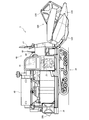
- FIG. 1 is a left side view of a combine to which a handling cylinder according to an embodiment of the present invention can be applied.
- FIG. 2 is a right side view of the combine.
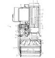
- FIG. 3 is a plan view of the combine.
- FIG. 4 is a transmission schematic diagram of the combine.
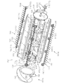
- FIG. 5 is a side view of the handling cylinder.
- FIG. 6 is a perspective view of the handling cylinder.
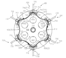
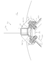
- 7 is a cross-sectional view taken along line VII-VII in FIG. 8 is a cross-sectional view taken along line VIII-VIII in FIG. 9 is a cross-sectional view taken along the line IX-IX in FIG.
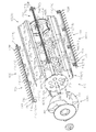
- FIG. 10 is an exploded perspective view of the handling cylinder, showing a state viewed from the front.
- FIG. 10 is an exploded perspective view of the handling cylinder, showing a state viewed from the front.
- FIG. 11 is an exploded perspective view of the handling cylinder, showing a state viewed from the rear.
- 12 is an exploded perspective view of a cross section taken along line VII-VII in FIG.
- FIG. 13 is an enlarged view of a portion XIII in FIG.
- FIG. 14 is an enlarged view of a state in which the tooth handling frame is attached at a position displaced from the attachment position shown in FIG. 13 to the upstream side in the rotation direction of the handle shaft and radially outward of the handle shaft.
- FIG. 15 is an enlarged view of a state in which the tooth handling frame is attached at a position displaced from the attachment position shown in FIG. 13 to the downstream side in the rotation direction of the handle shaft and radially outward of the handle shaft.
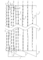
- FIG. 16 is a schematic development view of the handling cylinder.
- 1 to 4 show a left side view, a right side view, a plan view, and a transmission schematic diagram of the combine 1, respectively.
- the combine 1 includes a traveling machine body 10, a pair of left and right traveling crawlers 20 connected to the traveling machine body 10, an engine 25 mounted on the traveling machine body 10, A transmission 30 inserted in a transmission path from the engine 25 to the traveling crawler 20; an operating unit 40 mounted on the traveling machine body 10; a cutting unit 100 connected to the front of the traveling machine body 10; A threshing device 200 for threshing the harvested cereals harvested by the reaping unit 100 and a Glen tank 50 for storing the grains generated by the threshing device 200 are provided.
- the operating unit 40 is disposed at the front of the traveling machine body 10 and on one side in the machine body width direction.
- the one side and the other side in the body width direction mean the right side and the left side of the combine 1 in the forward direction.
- the driving unit 40 includes a driver seat 41 on which a driver can be seated and various operation members arranged in the vicinity of the driver seat 41.
- the operation members include a steering operation member 42 that changes the traveling direction of the combine 1, a main transmission operation member 43 and a sub-transmission operation member 44 that change the traveling speed of the combine 1, driving of the threshing device 200, and A threshing clutch operating member 45 for switching the stop and a cutting clutch operating member 46 for switching the driving and stopping of the reaping device 100 are included.
- the engine 25 is supported by the traveling machine body 10 using a space below the operation unit 40.
- the engine 25 includes an engine body 26 supported by the traveling machine body 10 in a space below the operation unit 40, a first output shaft 27a extending from the engine body 26 to the other side in the machine body width direction, and the engine It has the 2nd and 3rd output shafts 27b and 27c extended from the main body 26 to the one body width direction side.
- the transmission 30 is configured to change the rotational power operatively input from the engine 25 and output it to the pair of traveling crawlers 20.
- the transmission 30 is disposed below the driving unit 40 in front of the engine 25.
- the transmission 30 includes a transmission case 31 supported by the traveling body 10, a transmission input shaft 32 extending from the transmission case 31 to the other side in the body width direction, and the transmission input shaft 32. And a speed change mechanism that changes the input rotational power.
- the transmission 30 is a hydraulic continuously variable transmission (HST) that performs a continuously variable transmission in response to an operation on the main transmission operating member 43 as the transmission mechanism.
- a main transmission 35 (see FIG. 4) and the like, a gear-type transmission that operatively inputs rotational power from the main transmission 35, and performs multi-stage transmission in response to an operation on the auxiliary transmission operation member 44, and the like Auxiliary transmission device (not shown).
- the pump shaft of the HST 35 functions as the transmission input shaft 32.
- the reaping device 100 is connected to the traveling machine body 10 so as to be movable up and down, and the height can be adjusted by a lifting hydraulic cylinder device 60 (see FIG. 1).
- the lifting hydraulic cylinder device 60 is supplied with hydraulic oil from a hydraulic pump 28 (see FIG. 4) attached to the engine 25.
- the reaping device 100 is disposed in the feeder house 110 and a feeder house 110 that defines a conveyance path for sending the reaped cereals toward the mouth provided in the front portion of the handling chamber 201 in the threshing device 200.
- Supply conveyor 115 a horizontally long bucket-shaped grain header 120 connected to the front end of the feeder house 110, a scraping auger 125 disposed in the grain header 120, and above and above the scraping auger 125.
- a cutting reel 140 provided with a tine bar and a cutting blade 140 disposed in front of and below the scraping auger 125.
- the supply conveyor 115 is disposed along the body width direction on the conveyance direction end side (rear side) along the body width direction on the cutting input shaft 116 disposed on the conveyance direction start end side (front side).
- the lifting hydraulic cylinder device 60 (see FIG. 1) is interposed between the lower surface of the feeder house 110 and the traveling machine body 10, and the reaping device 100 includes the lifting hydraulic cylinder.
- the device 60 can move up and down around the cutting input shaft 116.
- the harvesting device 100 further includes a pair of left and right weed bodies 150 extending forward from both sides of the grain header 120 in the body width direction. Yes.
- the uncut rice culm between the pair of right and left weed bodies 150 is cut by the cutting blade 140 while the tip side is being scraped by the scraping reel 130.
- the harvested cereals harvested by the cutting blade 140 are collected in the grain header 120 by the scraping auger 125 in the vicinity of the front end opening of the feeder house 110, and from the front end opening of the feeder house 110 by the supply conveyor 115. It is transported toward the rear end opening and put into the handling chamber 201 from the handling opening.
- the combine 1 includes a front rotor mechanism 160 that feeds the harvested cereals fed from the supply conveyor 115 to the handling port of the handling chamber 201. ing.
- the front rotor mechanism 160 includes a front rotor drive shaft 161 along the body width direction between the conveyance end of the supply conveyor 115 and the handling port, and a front supported by the front rotor drive shaft 161 so as not to be relatively rotatable.
- the harvested cereal mash that has been transported to the transport end of the supply conveyor 115 is put into the handling chamber 201 from the handling opening by the front rotor 162. .
- the threshing apparatus 200 includes a handling chamber 201 formed by a machine frame erected on the traveling machine body 10, and a handling cylinder shaft disposed along the front-rear direction. 210, a handling cylinder 600 according to the present embodiment housed in the handling chamber 201 in a state of being rotationally driven by the handling cylinder shaft 210, and a receiving net 230 (below the handling cylinder 220) 1). Details of the barrel 600 will be described later.
- cereals threshed from the harvested cereal culm by the handling barrel 600 are selected by the threshing apparatus 200 as described below. A sorting process is performed by the mechanism 250. On the other hand, cereals such as sawdust larger than the mesh opening of the receiving net 230 are discharged from a dust outlet 205 provided behind the handling chamber 201 by the conveying action of the handling cylinder 220.
- a plurality of dust feeding valves (not shown) whose mounting angle can be changed are provided above the handling cylinder 220, and the grain removal in the handling chamber 201 is performed by changing the mounting angle of the dust feeding valve.
- the conveyance speed of the image may be adjustable.
- the threshing apparatus 200 further includes the grain sorting mechanism 250 that sorts grains from the thresh leaked from the receiving net 230.
- the grain sorting mechanism 250 includes a swing sorting body 260 that performs specific gravity sorting on the cereals leaked from the receiving net 230, and a sorting wind supply that feeds the sorting wind toward the swing sorting body 260.
- a body 280 A body 280.
- the swing sorting body 260 includes a swing sorting drive shaft 261 driven by power operatively transmitted from the engine 25 and a swing sorting board 265 swung by the swing sorting drive shaft 261.
- the swing sorter 265 includes Glen pan, chaff sheave, Glen sheave, Strollac, and the like.
- the selected wind supply body 280 has a red pepper shaft 281 driven by power operatively transmitted from the engine 25, and a red pepper fan 285 driven by the red pepper shaft 281.
- the grain sorting mechanism 250 further selects a grain (the first thing such as a refined grain) selected from the cereal by the specific gravity sorting action by the swing sorter 260 and the wind sorting action by the sorting wind supply body 280.
- the first container 301 to be aggregated, the first conveyor mechanism 310 disposed in the first container 301, and the first object sent by the first conveyor mechanism 310 are conveyed into the Glen tank 50.
- the second and third output shafts 27b and 27c of the engine 25 drive the hydraulic pump 28 and the cooling fan 29, respectively.
- the first output shaft 27 a of the engine 25 outputs a traveling system rotational power for driving the traveling member 20.
- the first output shaft 27a is operatively connected to the transmission input shaft 32 via a traveling endless transmission mechanism 400 such as a pulley transmission mechanism.
- the first output shaft 27a further outputs work system rotational power for driving the threshing apparatus 200 and the reaping apparatus 100.
- the working system rotational power is transmitted to the threshing device 200 and the reaping device 100 via a pipe shaft 500 that is extrapolated so as to be relatively rotatable on one side in the body width direction of the tang shaft 281. It has become so.
- the tang shaft 281 is supported by a machine frame that forms the handling chamber 201 so as to be rotatable about its axis, and of the tang shaft 281, a machine that forms the handling chamber 201.
- the pipe shaft 500 is extrapolated so as to be relatively rotatable at a portion extending from the frame to one side in the body width direction (one side in the body width direction of the tang shaft 281).
- the first output shaft 27a is operatively connected to the pipe shaft 500 via a first working endless transmission mechanism 410 such as a pulley transmission mechanism.
- the first working system endless body transmission mechanism 410 is connected to the threshing device 200 and the reaping device 100 from the engine 25 in response to an operation on the threshing clutch operating member 45.
- a threshing clutch 290 for engaging and disengaging power transmission is inserted.
- a handling cylinder input shaft 510 is provided in front of the handling chamber 201 along the body width direction.
- the handling cylinder input shaft 510 is supported by a transmission case 520 disposed in front of the handling chamber 201 so as to be rotatable about its axis.
- the barrel input shaft 510 has one side in the body width direction extending outward from the transmission case 520, and is positioned in a gap between the operation unit 40 and the threshing apparatus 200 in the body width direction.
- the other side of the machine body width direction is supported in the transmission case 520 so as to be rotatable about its axis while being inserted into the transmission case 520.
- the pipe shaft 500 is operatively connected to the handling cylinder input shaft 510 via a second working system endless body transmission mechanism 420 such as a pulley transmission mechanism.
- a second working system endless body transmission mechanism 420 such as a pulley transmission mechanism.
- the front end of the handling cylinder shaft 210 is inserted into the transmission case 520 and is operatively connected to the handling cylinder input shaft 510 in the transmission case 520.
- the other side in the body width direction of the handling cylinder input shaft 510 is terminated in the transmission case 520, and the handling cylinder shaft 210 is interposed in the transmission case via a bevel gear mechanism 530. Operatively connected to the front end of the.
- a work system extending in the body width direction with one side in the body width direction connected to the other side in the body width direction of the barrel input shaft 510 in the transmission case 520 so as not to be relatively rotatable around the axis.
- a transmission shaft 540 is provided, and rotational power from the engine 25 is transmitted to the reaping device 100 and the sorting mechanism 250 via the work system transmission shaft 540.
- the working system transmission shaft 540 is connected to the handling cylinder input shaft 510 so as not to be relatively rotatable around the axis by using the bevel gear mechanism 530.
- the drive-side bevel gear of the bevel gear mechanism 530 is provided with a spline hole into which the other side in the machine body width direction of the barrel input shaft 510 is inserted so as not to be relatively rotatable, and the work system transmission shaft 540 has one side in the machine body width direction. The side is inserted into the spline hole of the drive side bevel gear so as to be connected to the cylinder input shaft 510 so as not to rotate relative to the axis.
- the combine 1 has the front rotor mechanism 160, and power is transmitted from the work system transmission shaft 540 to the reaping device 100 via the front rotor drive shaft 161.
- the working system transmission shaft 540 is operatively connected to the front rotor drive shaft 161 via a third working system endless body transmission mechanism 430 such as a pulley transmission mechanism.
- the third working system endless body transmission mechanism 430 is provided with a cutting clutch 190 that engages and disengages power transmission in response to an operation on the cutting clutch operating member 46. .
- the front rotor drive shaft 161 is operatively connected to the cutting input shaft 116 via a fourth working endless transmission mechanism 440 such as a sprocket transmission mechanism.
- a forward / reverse switching mechanism 170 is interposed between the front rotor drive shaft 161 and the cutting input shaft 116, and the fourth work system endless
- the body transmission mechanism 440 transmits rotational power from the front rotor drive shaft 161 to the forward / reverse switching mechanism 170.
- a cutting transmission shaft 105 is disposed coaxially with the cutting input shaft 116 on the other side in the body width direction of the cutting input shaft 116, and the front rotor driving shaft 161 is connected to the fourth working system transmission mechanism 455. Is operatively connected to the cutting transmission shaft 105 via The forward / reverse switching mechanism 170 is interposed between the cutting transmission shaft 105 and the cutting input shaft 116.
- the grain header 120 is provided with a header drive shaft 121 along the width direction of the machine body and a scraping shaft 122 along the width direction of the body while supporting the scraping auger 125, and the cutting input shaft 116.
- One side in the body width direction is operatively connected to the header drive shaft 121 via a header drive chain 460, and the header drive shaft 121 is operatively connected to the take-up shaft 122 via a take-up drive chain 461.
- the drive shaft 122 is operatively connected to a reel shaft 131 that supports the drive reel 130.
- the scraping shaft 122 is operatively connected to the intermediate shaft 466 via a first reel drive chain 465, and the intermediate shaft 466 is operatively connected to the reel shaft 131 via a second reel drive chain 467. .
- header drive shaft 121 is also operatively connected to the cutting blade 140 via a cutting blade drive crank mechanism 470.
- the working system transmission shaft 540 is also operatively connected to the flange shaft 281 via a fifth working system endless body transmission mechanism 450 such as a pulley transmission mechanism.
- the first conveyor mechanism 310 includes a first conveyor shaft 311 provided in the first basket 301 and a first conveyor 312 provided on the first conveyor shaft 311. And have.
- the cereal conveyor mechanism 320 is disposed in a cereal cylinder 325 having a lower end side communicated with one side in the body width direction of the first basket 301 and an upper end side communicated with an inlet of the Glen tank 50, and a lower end side thereof. It has a cerealing shaft 321 operatively connected to the first conveyor shaft 311 and a cerealing conveyor 322 provided on the cerealing shaft 321.
- the second conveyor mechanism 330 has a second conveyor shaft 321 disposed in the second basket 302 and a second conveyor 322 provided on the second conveyor shaft 321.
- the second return conveyor mechanism 340 has a lower return side that communicates with one side in the body width direction of the second basket 302 and an upper end that opens toward the sorting start end side of the swing sorter 265. And a second reduction shaft 341 operatively connected to the second conveyor shaft 321 and a second reduction conveyor 342 provided on the second reduction shaft 341.
- the other side in the body width direction of the tang shaft 281 is operatively connected to the other side in the body width direction of the first conveyor shaft 311 and the second conveyor shaft 321 via the pulley transmission mechanism 480 for conveyor. .
- the other side in the machine width direction of the second conveyor shaft 321 is operatively connected to the other side in the machine width direction of the swing sorting shaft 261 via a pulley sorting pulley transmission mechanism 485.
- FIG. 5 and 6 show a side view and a perspective view of the handling cylinder 600, respectively.
- 7 to 9 are sectional views taken along lines VII-VI, VIII-VIII, and IX-IX in FIG. 5, respectively.
- 10 and 11 are exploded perspective views of the handling cylinder 600.
- FIG. 5 and 6 show a side view and a perspective view of the handling cylinder 600, respectively.
- 7 to 9 are sectional views taken along lines VII-VI, VIII-VIII, and IX-IX in FIG. 5, respectively.
- 10 and 11 are exploded perspective views of the handling cylinder 600.
- the barrel 600 includes a barrel body 610 that is supported on the barrel shaft 210 so as not to be relatively rotatable, and a plurality of tooth handling frames 700 that are detachably connected to the barrel body 610.
- the barrel body 610 includes the front plate 620 and the rear plate 630 fixed to the barrel shaft 210, and the front side so as to cover the circumference of the barrel shaft 210.
- the front plate 620 includes a front plate body 621 that is supported by the handling cylinder shaft 210 so as not to be relatively rotatable, and a front flange 625 that extends rearward from the front plate body 621. .
- the front flange 625 is fixed to the rear surface of the front plate body 621 by welding or the like.
- the rear plate 630 is supported by the barrel shaft 210 so as not to rotate relative to the front plate body 621 at a position spaced in the axial direction of the barrel shaft 210.
- a rear plate body 631 and a rear flange 635 extending forward from the rear plate body 631 are provided.
- the rear flange 635 is fixed to the front surface of the front plate body 631 by welding or the like.
- the shielding plate 650 is fixed to the front mounting flange 625 and the rear mounting flange 635 so as to surround the outer periphery of the barrel shaft 210.
- the shielding plate 650 has a plurality of divided shielding plates divided in the circumferential direction of the barrel shaft 210, and at least one of the plurality of divided shielding plates is in relation to the remaining divided shielding plates. It is detachably connected.
- the shielding plate 650 is divided into first to third divided shielding plates 650 (1) divided in the circumferential direction of the barrel shaft. ⁇ 650 (3).
- FIG. 12 is an exploded perspective view of a cross section taken along line VII-VII in FIG.
- the first and second divided shielding plates 650 (1) and 650 (2) are welded to the front mounting flange 625 and the rear mounting flange 635 by welding or the like. It is fixed inseparably.
- the third divided shielding plate 650 (3) is detachably connected to the first and second divided shielding plates 650 (1) and 650 (2) by a fastening member 655 such as a bolt.
- the shielding plates 650 that form the barrel body 610 so that the plurality of tooth handling frames 700 are arranged at equal intervals along the axial direction of the barrel shaft 210 and in the circumferential direction of the barrel shaft 210. It is detachably connected to.
- the tooth handling frame 700 includes a long support bar 710 and a plurality of tooth handling 730 arranged at a predetermined pitch along the longitudinal direction of the support bar 710.
- the support bar 710 includes a long bar main body 711 to which the plurality of teeth handling teeth 730 are fixed, and a plurality of mounting brackets 715 connected to the bar main body 711 in a state of being separated in the longitudinal direction of the bar main body 711. And have.
- the bar body 711 is a hollow member.
- the mounting bracket 715 has a pair of mounting pieces 716 extending to one side and the other side in the width direction of the bar main body 711 with the bar main body 711 interposed therebetween.
- the pair of attachment pieces 716 are provided with through holes 717 (see FIGS. 13 to 15 below).
- the shield plate 650 is provided with an attachment hole at a position corresponding to the through hole 717 of the attachment piece 716, and the support bar 711 includes the through hole 717 formed in the attachment piece 716 and the shield plate 650. It is detachably connected to the shielding plate 650 by a fastening member 720 such as a bolt that is inserted into an attachment hole formed in the above.
- the handling cylinder 600 is supported between the front plate 620 and the rear plate 630 so as not to rotate relative to the handling cylinder shaft 210.
- the second intermediate plate 640 (2 ) And are provided between the first intermediate plate 640 (1) and the first intermediate plate 640 (1) and the rear plate 630.
- Each of the first and second intermediate plates 640 (1) and 640 (2) includes an intermediate plate body 641 that is supported relatively non-rotatably on the handling shaft 210, and a radially outer end of the intermediate plate body 641. And an intermediate mounting flange 645 extending in the axial direction of the barrel cylinder 210 from the portion.
- the support bar 710 is provided with the first to fourth mounting brackets 715 arranged in order from the front to the rear.
- the first to fourth mounting brackets 715 are respectively connected to the front mounting flange 625 of the front plate 620, the intermediate mounting flange 645 of the first intermediate plate 640 (1) with respect to the axial direction of the handling cylinder shaft 210.
- the intermediate mounting flange 645 of the second intermediate plate 640 (2) and the rear mounting flange 635 of the rear plate 630 are disposed at the same position.
- a mounting hole is formed in the mounting bracket 715 at a position facing the through hole 717.
- the fastening member 720 for detachably connecting the first to fourth mounting brackets 715 to the shielding plate 650 includes the through holes 717 of the mounting bracket 715 and the corresponding mounting members of the shielding plate 650. In addition to the holes, they are inserted through the corresponding mounting holes of the mounting flanges 625, 635, and 645 and fastened together.
- the tooth handling frame 700 is connected to the outer surface of the shielding plate 650 via the mounting bracket 715.
- the outer surface of the shielding plate 650 and the bottom surface of the bar body 711 in the radial direction with respect to the handling shaft 210 as to the radial direction of the handling shaft 210).
- a gap 765 may be formed between the inner surface and the inner surface.
- the mounting bracket 715 adjacent to the outer surface of the shielding plate 650 in the axial direction of the handling cylinder shaft 210 in the gap 765 Is provided with a closing plate 670 that covers the portion located between them from the downstream side with respect to the rotation direction of the barrel shaft 210, and effectively prevents the harvested grain from being caught in the gap 765 by the closing plate 670. Is decreasing.
- the handling cylinder 600 has the following configuration, so that the attachment position of the tooth handling frame 700 can be adjusted with respect to the circumferential direction and the radial direction of the handling cylinder shaft 210.
- the shielding plate 650 is formed to have a plurality of convex portions 660 that project radially outward in a cross-sectional view.
- the plurality of convex portions 66 are provided in the same number as the tooth handling frame 700, and are arranged at equal intervals around the axis of the treatment barrel shaft 210.
- the handling cylinder 600 is provided with six tooth handling frames 700. Therefore, the shielding plate 650 includes the six convex portions 660 around the axis of the handling cylinder shaft 210.
- FIG. 13 shows an enlarged view of a portion XIII in FIG.
- the pair of mounting pieces 716 of the mounting bracket 715 are arranged in a state where the bar main body 711 is positioned radially outward of the convex portion 660. It is formed along the side surface of the one side and the other side of the shaped portion 660.
- the through hole 717 formed in the mounting piece 716 is a long hole whose longitudinal direction is along the circumferential direction of the handling cylinder shaft 210.
- the mounting position of the tooth handling frame 700 is displaced from the reference mounting position shown in FIG. 13 to the upstream side in the rotational direction and the radially outward side of the barrel cylinder 210 (see FIG. 14). And it can displace from the reference
- Reference numeral 725 in FIGS. 14 and 15 is a spacer for filling a gap generated by displacing the mounting position of the tooth handling frame 700 from the reference mounting position.
- the handling part 600B in addition to the handling part 600B formed by the shielding plate 650 and the tooth handling frame 700, the handling part 600B is further forward.
- a scraping portion 600 ⁇ / b> A is provided that conveys the harvested cereal meal toward the handling portion 600 ⁇ / b> B as the handling cylinder shaft 210 rotates.
- the scraping portion 600 ⁇ / b> A is a plurality of spiral blades 760 that convey the harvested cereals toward the handling portion 600 ⁇ / b> B according to the rotation of the handling shaft 210, and the like around the axis of the handling shaft 210. It has a plurality of spiral blades 760 arranged at intervals.
- the scraping portion 600A is supported by the handling cylinder shaft 210 so as not to be relatively rotatable and a rear end surface thereof is connected to the front plate 620 via a fastening member.
- a plurality of spiral blades 760 are provided on the outer peripheral surface of the drum body 750.
- the handling cylinder axis is improved in order to improve the hitting efficiency of the harvesting cereal by the handling teeth 730. It is desirable that the tooth handling teeth of the tooth handling frames 700 adjacent to each other in the circumferential direction of 210 are misaligned with respect to the axial direction of the barrel cylinder 210.
- a spiral blade 760 is provided in front of the tooth handling frame 700 that performs the threshing process by striking the harvested grain culm toward the tooth handling frame 700.
- the speed at which the harvested cereals are conveyed at the handling part 600B including the tooth handling frame 700 is higher than the speed at which the harvested cereals are conveyed at the scraping part 600A including the spiral blade 760. Since it becomes late, the retention of the harvested cereal meal is likely to occur in the vicinity of the boundary between the scraping portion 600A and the handling portion 600B. In order to improve the threshing efficiency, it is desirable to prevent the retention of the harvested cereal as much as possible.
- FIG. 16 is a schematic development view of the handling cylinder 600.
- the two spiral blades 760 are provided at equal intervals (180 degree intervals) around the axis of the handling cylinder shaft 210, and the six tooth handling frames 700 are provided on the handling cylinder shaft 210. It is provided at regular intervals (60 degree intervals) around the axis.
- the distance from the front end to the center of the foremost tooth handling 730F is L, and the pitch between adjacent tooth handling teeth 730 is P.
- the distance between the first and second tooth handling frames 700 (1) in one array and the center of the foremost tooth handling 730F is L + (P / 3) and adjacent tooth handling 730
- the distance from the front end portion to the center of the foremost tooth 730F is L + (2P / 3).
- L is P / 3.
- first spiral blade 760 (1) with respect to the circumferential position with respect to the axial line of the handle cylinder shaft 210 of the first tooth handling frame 700 (3) of the third array.
- One of the first and second arrays in the present embodiment, the tooth handling frame 700 (2) in the second array) in order toward the downstream side in the rotation direction R of the handle cylinder shaft 210.
- First tooth handling frame, the first tooth handling frame of the other of the first and second arrays (the first array of tooth handling frames 700 (1) in the present embodiment), the second array of the third array.
- a tooth handling frame, one second tooth handling frame of the first and second arrays, and the other second tooth handling frame of the first and second arrays are arranged.
- the tooth handling 730 ⁇ / b> F located at the forefront from the front end portion is displaced while the tooth handling 730 of the tooth handling frame 700 adjacent in the circumferential direction of the handling cylinder shaft 210 is displaced in the axial direction of the handling cylinder shaft 210.
- a third tooth arrangement frame 700 (3) of the third arrangement having the largest distance to the rear end of the first spiral blade 760 (1) is disposed in proximity to the rear edge of the first spiral blade 760 (1) and ) Is disposed close to the rear end of the other spiral blade (second spiral blade 760 (2)).
- the harvested cereals stay in the vicinity of the boundary between the rear end of the spiral blade 760 and the front end of the tooth handling frame 700. It can be effectively prevented.
- the first tooth handling frame 700 (1) in the third arrangement is the first spiral blade 760 (1) with respect to the circumferential position with respect to the axis of the handling cylinder shaft 210. It arrange
- a space between the rear end of the second spiral blade 760 (2) and the foremost tooth handling 730F in the second tooth handling frame 700 (3) of the third arrangement adjacent to the second spiral blade 760 (2) is formed. Can be spread.
- the distance from the rear end to the center of the rearmost tooth handling 730R is L + (2P / 3).
- the distance from the rear end to the center of the rearmost tooth handling 730R is L.
- the distance between the tooth handling frame 700 (1) in the first array and the tooth handling frame 700 (3) in the third array from one end to the tooth handling closest to the one end. Can be formed by a common tooth handling frame 700C in which L is L and the distance from the other end to the tooth handling closest to the other end is L + (2P / 3).
- the common tooth handling frame 700C by arranging the one end portion of the common tooth handling frame 700C so as to form a front end portion, it is used as the tooth arrangement frame 700 (1) of the first arrangement, and the other end of the common tooth treatment frame 700C.
- the portions so as to form the front end portion it can be used as the tooth handling frame 700 (3) of the third arrangement.
- three types of tooth treatment pitches are provided by two types of tooth treatment frames (that is, tooth treatment frames used as the common tooth treatment frame 700C and the second arrangement tooth treatment frame 700 (2)). Can be obtained.
- the common tooth handling frame 700 ⁇ / b> C is arranged so that one end of the common tooth handling frame 700 ⁇ / b> C forms a front end, and the common tooth handling frame 700 ⁇ / b> C is used as the tooth handling frame 700 (1) of the first arrangement for a predetermined threshing operation time.
- the third tooth arrangement frame 700C is used by replacing the front and rear of 700C, and the other end portion of the common tooth treatment frame 700C forms a front end portion.
- the front and rear of the common tooth handling frame 700C are replaced and used as the tooth handling frame 700 (1) of the first array. Can be used effectively without waste.
- the tooth arrangement frame 700 (2) of the second arrangement is from the distance from one end to the tooth treatment closest to the one end and from the other end.
- the distance to the tooth handling closest to the other end is set to L + (P / 3).
- the tooth handling frame 700 (2) is arranged in the second array of tooth handling frames 700 (2).
- the tooth handling frame is By performing the threshing operation with the front and rear reversed arrangement, it is possible to effectively use the plurality of tooth handling frames of the tooth handling frame forming the tooth handling frame 700 (2) of the second array without waste.
- the handling cylinder 600 includes the two spiral blades 760 and the six tooth handling frames 700, but the invention is limited to such a form. Not.
- m spiral blades 760 (m is an integer of 2 or more) arranged at equal intervals around the axis of the cylinder barrel 210, and m ⁇ arranged at equal intervals around the axis of the cylinder barrel 210.
- a handling cylinder hereinafter, referred to as a handling cylinder of the first configuration
- n is a multiple of 2 tooth handling frames 700
- the circumferential direction of the handling cylinder shaft 210 is adopted by adopting the following configuration.
- the harvested cereal meal stays in the vicinity of the boundary between the rear end of the spiral blade 760 and the front end of the tooth-handling frame 700. This can be effectively prevented.
- the handling cylinder includes two spiral blades 760 and the four tooth handling frames 700, and two spiral blades 760 and the eight tooth handling frames 700. And a handling cylinder having three spiral blades 760 and six tooth handling frames 700 are applicable.
- the distance from the front end to the center of the foremost tooth handling 730F is L, and the pitch between adjacent tooth handling teeth 730 is P (P is a positive number).
- the distance from the first array of tooth handling frames 700 (1) to the center of the frontmost tooth handling 730F is L + (P / 2), and the pitch between adjacent tooth handling teeth 730 is P. It is assumed that the tooth handling frame 700 (2) in the second array is included.
- tooth handling frame 700 (2) of the second array of the second arrangement of the spiral blades 760 of the m spiral blades 760 with respect to the circumferential position with respect to the axis of the handle cylinder shaft 210 is used.
- the first and second arrangements of tooth handling frames 700 (1) and 700 (2) are alternately arranged around the axis of the handling cylinder shaft 210 in a state of being arranged closest to the rear end.
- a handling cylinder (hereinafter, referred to as a handling cylinder of the second configuration) including xn (n is a multiple of 3) tooth handling frames 700 can have the following configuration.
- the distance from the front end to the center of the foremost tooth handling 730F is L, and the pitch between adjacent tooth handling teeth 730 is P (P is a positive number).
- the distance from the first array of tooth handling frames 700 (1) to the center of the frontmost tooth handling 730F is L + (P / 3), and the pitch between adjacent tooth handling teeth 730 is P.
- the distance between the tooth arrangement frame 700 (2) of the second array and the center of the frontmost tooth treatment 730F is L + (2P / 3), and the pitch between adjacent tooth treatments 730 is P. It is assumed that the tooth handling frame 700 (3) in the third arrangement is included.
- the tooth arrangement frame 700 (3) in the third arrangement of the spiral blades 760 out of the m spiral blades 760 with respect to the circumferential position with respect to the axis of the barrel axis 210 is used.
- One of the tooth handling frames in the first and second arrays is arranged closest to the rear end, and further, in order from the tooth handling frame 700 (3) in the second array to the downstream side in the rotation direction of the handle shaft 210.
- the other tooth handling frame of the first and second arrays is arranged.
- the tooth handling frame 700 (3) of the third arrangement is always disposed in proximity to the rear ends of the plurality of spiral blades 760. Therefore, in the handling cylinder of the second configuration, the harvested cereals are effectively prevented from staying in the boundary portion between the scraping part and the handling part while efficiently hitting the harvested cereals with the tooth handling. be able to.
- the above-mentioned for effectively preventing the harvested cereal from staying in the boundary portion between the scraping part 600A and the handling part 600B while efficiently hitting the harvested cereal with the handle 730 can also be applied to a handling cylinder having a structure without the shielding plate 650.
- the handling portion is arranged around the axis of the front and rear plates fixed to the handling cylinder shaft, and rotates around the axis along with the handling cylinder axis. Even in a structure having a plurality of tooth handling frames supported by the rear plate and in which the internal space of the handling part is in communication with the outside, The above-described configuration for effectively preventing the harvested cereals from staying in the boundary portion between the scraping portion and the handling portion can be effectively applied.
Landscapes
- Life Sciences & Earth Sciences (AREA)
- Environmental Sciences (AREA)
- Threshing Machine Elements (AREA)
Abstract
本発明に係る扱胴は、扱胴軸に固着された前側プレート及び後側プレートと前記扱胴軸の回りを覆うように前記前側プレート及び前記後側プレートに固着された遮蔽板とを含む扱胴本体と、長尺の支持バー及び前記支持バーの長手方向に沿って間隙を存しつつ配置された複数の扱歯とを含む複数の扱歯フレームとを備え、前記複数の扱歯が前記支持バーから径方向外方へ延びる状態で前記複数の支持バーが前記扱胴軸に略平行で且つ前記扱胴軸の周方向に間隔を存しつつ配置されるように、前記複数の支持バーが前記遮蔽板の外表面に着脱可能に固着されている。
Description
本発明は、扱室に供給される刈取穀稈に対して脱穀処理を行う扱胴に関する。
扱室に供給される刈取穀稈に対して脱穀処理を行う扱胴として、扱胴軸の前部及び後部に固着された前側プレート及び後側プレートと、前記扱胴軸の周方向に沿って配置されるように前記前側プレート及び前記後側プレートに支持された複数の支持バーと、前記複数の支持バーのそれぞれに径方向外方へ延在するように設けられた複数の扱歯とを有する扱胴が提案されている(例えば下記特許文献1~10参照)。
前記扱胴においては、前側プレート、後側プレート及び複数の支持バーによって形成される扱胴本体の内部空間に刈取穀稈が自由に入り込む為、刈取穀稈が前記扱胴軸や前記支持バーに巻き付きやすく、脱穀効率が悪化する可能性がある。
なお、特許文献1~5には、前記支持バーとして中空のパイプ部材を用いること、並びに、前記中空パイプ部材の長手方向に直交する幅方向に取付孔を貫通させ、前記取付孔に扱歯を挿入させて前記扱歯を前記扱胴軸を基準とした径方向に関し外方へ延在させた状態で前記扱歯を径方向内側及び外側の2箇所で前記中空パイプ部材に固着させることが開示されている。
前記特許文献1~10に記載の扱胴に対し、下記特許文献11には、扱胴軸の前部及び後部に固着された前側プレート及び後側プレートと、前記扱胴軸の周方向に沿って配置されるように前記前側プレート及び前記後側プレートに支持された複数の支持バーと、前記複数の支持バーのそれぞれに径方向外方へ延在するように設けられた複数の扱歯とを有する扱胴において、隣接する支持バー間の少なくとも一部を覆う板状の遮蔽板であって、隣接する支持バーの外周面同士を連結する仮想外表面よりも径方向内方に位置する遮蔽板を備えた扱胴が開示されている。
前記特許文献11に記載の扱胴は、前記支持バーに支持された複数の扱歯による脱穀作用を得つつ、前記遮蔽板の存在によって刈取穀稈が扱胴本体の内部空間に入り込むことを有効に防止することができ、さらに、前記遮蔽板を前記仮想外表面より径方向内方に位置させることで、前記遮蔽板と扱室の内面との間の処理空間の可及的な拡大を図っている点において、有用である。
ところで、脱穀処理に際し前記扱歯には大きな負荷が掛かる為、前記扱歯のメンテナンス及び/又は交換を行う必要が生じ得る。
この点に関し、前記特許文献11に記載の脱穀装置においては、前記支持バー自体が扱胴本体を形成しており、前記支持バーを取り外すことは非常に厄介な作業となる。
この点に関し、前記特許文献11に記載の脱穀装置においては、前記支持バー自体が扱胴本体を形成しており、前記支持バーを取り外すことは非常に厄介な作業となる。
なお、隣接する支持バー間を遮蔽板によって覆うことで、扱胴本体の内部への刈取穀稈の侵入を防止することは、前記特許文献2にも開示されているが、この特許文献2に記載の構成においては、遮蔽板が支持バーに溶接固定されており、従って、支持バーのメンテナンス及び/又は交換作業はより厄介なものとなる。
また、前記複数の扱歯の配列に関し、周方向に隣接する扱歯フレーム同士においては扱歯の前後方向位置を位置ズレさせることも提案されている(例えば、前記特許文献1、3、4、8及び10~12)。
特に、前記特許文献1及び11には、周方向に隣接する扱歯フレーム間において、扱歯の配列ピッチを1/2だけ位置ズレさせることで、刈取穀稈に対する脱穀処理を効率的に行えることが記載されている。
特に、前記特許文献1及び11には、周方向に隣接する扱歯フレーム間において、扱歯の配列ピッチを1/2だけ位置ズレさせることで、刈取穀稈に対する脱穀処理を効率的に行えることが記載されている。
ところで、前記扱胴フレームについては、前記特許文献1、4、8及び10~12に記載されているように、前記扱胴軸回りに6本を配置させるのが一般的である。
しかしながら、前記特許文献1及び11に記載されているような、前記扱胴フレームより前方に掻込用螺旋羽根が設けられた扱胴においては、前記螺旋羽根から扱胴フレームへの刈取穀稈の流動性に関し、改善の余地があった。
しかしながら、前記特許文献1及び11に記載されているような、前記扱胴フレームより前方に掻込用螺旋羽根が設けられた扱胴においては、前記螺旋羽根から扱胴フレームへの刈取穀稈の流動性に関し、改善の余地があった。
詳しくは、前記特許文献1及び11に記載されている扱胴は、6本の前記扱胴フレームを有する扱ぎ部に加えて、前記扱胴軸の回転に応じて刈取穀稈を前記扱ぎ部へ向けて搬送する2枚の螺旋羽根であって、互いに対して前記扱胴軸の軸線回りに180度離間配置された2枚の螺旋羽根を有する掻込部を備えている。
前記掻込部においては、刈取穀稈は前記2枚の螺旋羽根によってスムースに後方へ搬送される一方で、前記扱ぎ部においては、刈取穀稈は前記扱歯によって打撃を受けつつ後方へ搬送されることになり、前記扱ぎ部での刈取穀稈の搬送速度は前記掻込部での搬送速度よりも遅くなる。
従って、螺旋羽根を有する前記掻込部を備えた扱胴においては、前記螺旋羽根の後端部と前記扱歯フレームの前端部との境界近傍において刈取穀稈の滞留が生じ易い。
しかしながら、前記特許文献の何れにも斯かる点に着目したものは存在しない。
しかしながら、前記特許文献の何れにも斯かる点に着目したものは存在しない。
本発明は、斯かる従来技術に鑑みなされたものであり、支持バー及び前記支持バーに固着された複数の扱歯を有する扱歯フレームが扱胴軸の軸線回りに複数個、配置されている扱胴であって、内部空間への刈取穀稈の侵入を有効に防止しつつ、前記扱歯フレームのメンテナンス及び/又は交換を容易に行うことができる扱胴の提供を、目的とする。
本発明は、前記目的を達成するために、扱胴軸に固着された前側プレート及び後側プレートと前記扱胴軸の回りを覆うように前記前側プレート及び前記後側プレートに固着された遮蔽板とを含む扱胴本体と、長尺の支持バー及び前記支持バーの長手方向に沿って間隙を存しつつ配置された複数の扱歯とを含む複数の扱歯フレームとを備え、前記複数の扱歯が前記支持バーから径方向外方へ延びる状態で前記複数の支持バーが前記扱胴軸に略平行で且つ前記扱胴軸の周方向に間隔を存しつつ配置されるように、前記複数の支持バーが前記遮蔽板の外表面に着脱可能に固着されている扱胴を提供する。
本発明に係る扱胴によれば、扱胴軸の回りを覆うように設けられた遮蔽板が前記扱胴軸と共に軸線回りに回転する扱胴本体を形成し、長尺の支持バーの長手方向に沿って複数の扱歯が配置されてなる複数の扱歯フレームが、前記扱歯が前記支持バーから径方向外方へ延び、前記複数の支持バーが前記扱胴軸に略平行で且つ前記扱胴軸の軸線回り周方向に間隔を存しつつ配置されるように、前記遮蔽板の外表面に着脱可能に固着されているので、刈取穀稈が扱胴の内部空間に入り込むことを有効に防止しつつ、前記扱胴本体を取り外すこと無く前記扱歯フレームを容易に脱着させることができる。従って、摩耗及び/又は損傷が生じ易い扱歯を有する扱歯フレームのメンテナンス及び/又は交換を容易に行うことができる。
好ましくは、前記遮蔽板は前記扱胴軸の周方向に分割された複数の分割遮蔽板を有するものとされ、前記複数の分割遮蔽板の少なくとも一つは、残りの分割遮蔽板に対して着脱可能に連結され得る。
一形態においては、前記支持バーは、前記複数の扱歯が固着される長尺のバー本体と、互いに対して前記バー本体の長手方向に離間されるように前記バー本体に設けられた複数の取付ブラケットとを有し、前記複数の取付ブラケットを介して前記遮蔽板に着脱可能に連結されるように構成される。
この場合、好ましくは、前記扱胴軸の径方向に関し前記バー本体及び前記遮蔽板の外表面の間に存する隙間のうちの少なくとも一部は、前記扱胴軸の回転方向に関し前記バー本体より下流側において前記遮蔽板の外表面から径方向外方へ延びるように設けられた閉鎖板によって覆われる。
好ましくは、前記遮蔽板は、横断面視において径方向外方へ突出する複数の凸状部であって、間隔を存しつつ周方向に沿って前記扱歯フレームと同数だけ設けられた複数の凸状部を有し、前記複数の扱歯フレームの前記支持バーは、対応する前記凸状部の径方向外方に位置するように前記遮蔽板の外表面に着脱可能に連結され得る。
前記支持バーは、前記扱胴軸の軸線方向に延び、前記複数の扱歯が固着されるバー本体と、前記バー本体に設けられ、前記遮蔽板に着脱可能に連結される複数の取付ブラケットとを有するものとされ、前記複数の取付ブラケットの各々は、前記バー本体を前記凸状部の径方向外方に位置させた状態で前記凸状部の一方側及び他方側の側面に沿うように前記バー本体から延びる一対の取付片を有するものとされる。
この場合、好ましくは、前記扱歯フレームは、前記一対の取付片に形成された貫通孔及び前記遮蔽板に形成された取付孔に挿通される締結部材によって前記遮蔽板に着脱自在に連結され、前記貫通孔は長手方向が前記扱胴軸の周方向に沿った長孔とされ得る。
前記種々の形態において、好ましくは、前記扱胴本体は、前記前側プレート及び前記後側プレートの間において前記扱胴に固着された第1中間プレートと、前記第1中間プレート及び前記後側プレートの間において前記扱胴に固着された第2中間プレートとを有するものとされ、前記遮蔽板は前記第1及び第2中間プレートにも固着される。
また、本発明は、扱胴軸回りに等間隔に配置されたm枚(mは2以上の整数)の螺旋羽根と前記扱胴軸の軸線回りに等間隔に配置されたm×n本(nは2又は3の倍数)の扱歯フレームとを備えた扱胴であって、前記扱胴軸の周方向に隣接する扱歯フレームの扱歯同士を前記扱胴軸の軸線方向に位置ズレさせつつ、螺旋羽根の後端部と扱胴フレームの前端部との境界近傍において刈取穀稈の滞留が生じることを有効に防止乃至は低減できる扱胴の提供を、目的とする。
前記目的を達成するために、本発明の第1態様は、扱胴軸の前側及び後側にそれぞれ相対回転不能に支持された掻込部及び扱ぎ部を備え、前記掻込部は、前記扱胴軸の回転に応じて刈取穀稈を前記扱ぎ部へ向けて搬送するように前記扱胴軸の軸線回りに等間隔に配置されたm枚(mは2以上の整数)の螺旋羽根を有し、前記扱ぎ部は、前記扱胴軸と共に前記扱胴軸の軸線回りに回転するように前記扱胴軸に沿った状態で前記扱胴軸の軸線回りに等間隔に配置されたm×n本(nは2の倍数)の扱歯フレームを有している扱胴であって、前記m×n本の扱歯フレームは、前端部から最前方の扱歯の中心までの距離がLとされ且つ隣接する扱歯間のピッチがP(Pは正数)とされた第1配列の扱歯フレームと、前端部から最前方の扱歯の中心までの距離がL+(P/2)とされ且つ隣接する扱歯間のピッチがPとされた第2配列の扱歯フレームとを含み、前記第2配列のうちの一の扱歯フレームが前記扱胴軸の軸線を基準とした周方向位置に関し前記m枚の螺旋羽根のうちの一の螺旋羽根の後端部に最も近接配置された状態で、前記第1及び第2配列の扱歯フレームが前記扱胴軸の軸線回りに交互に配置されている扱胴を提供する。
本発明の第1態様に係る扱胴によれば、扱胴軸の軸線回りに等間隔に配置されたm枚(mは2以上の整数)の螺旋羽根と、前記扱胴軸の軸線回りに等間隔に配置されたm×n本(nは2の倍数)の扱歯フレームとを有し、前記m×n本の扱歯フレームは、前端部から最前方の扱歯の中心までの距離がLとされ且つ隣接する扱歯間のピッチがP(Pは正数)とされた第1配列の扱歯フレームと、前端部から最前方の扱歯の中心までの距離がL+(P/2)とされ且つ隣接する扱歯間のピッチがPとされた第2配列の扱歯フレームとを含みものとされ、前記第2配列のうちの一の扱歯フレームが前記扱胴軸の軸線を基準とした周方向位置に関し前記m枚の螺旋羽根のうちの一の螺旋羽根の後端部に最も近接配置された状態で、前記第1及び第2配列の扱歯フレームが前記扱胴軸の軸線回りに交互に配置されているので、前記扱胴軸の周方向に隣接する扱歯フレームの扱歯同士が前記扱胴軸の軸線方向に位置ズレされた状態で、前記螺旋羽根の後端とこれに隣接する扱歯フレームの最前方に位置する扱歯との間に可及的に広い搬送空間を確保することができ、脱穀処理効率の可及的な向上を図ることができる。
また、本発明の第2態様は、前記目的を達成する為に、扱胴軸の前側及び後側にそれぞれ相対回転不能に支持された掻込部及び扱ぎ部を備え、前記掻込部は、前記扱胴軸の回転に応じて刈取穀稈を前記扱ぎ部へ向けて搬送するように前記扱胴軸の軸線回りに等間隔に配置されたm枚(mは2以上の整数)の螺旋羽根を有し、前記扱ぎ部は、前記扱胴軸と共に前記扱胴軸の軸線回りに回転するように前記扱胴軸に沿った状態で前記扱胴軸の軸線回りに等間隔に配置されたm×n本(nは3の倍数)の扱歯フレームを有している扱胴であって、前記m×n本の扱歯フレームは、前端部から最前方の扱歯の中心までの距離がLとされ且つ隣接する扱歯間のピッチがP(Pは正数)とされた第1配列の扱歯フレームと、前端部から最前方の扱歯の中心までの距離がL+(P/3)とされ且つ隣接する扱歯間のピッチがPとされた第2配列の扱歯フレームと、前端部から最前方の扱歯の中心までの距離がL+(2P/3)とされ且つ隣接する扱歯間のピッチがPとされた第3配列の扱歯フレームとを含み、前記第3配列のうちの一の扱歯フレームが前記扱胴軸の軸線を基準とした周方向位置に関し前記m枚の螺旋羽根のうちの一の螺旋羽根の後端部に最も近接配置された状態で、前記扱胴軸の回転方向下流側へ順に、前記第3配列の扱歯フレーム、前記第1及び第2配列の一方の扱歯フレーム、並びに、前記第1及び第2配列の他方の扱歯フレームが配置されているこ扱胴を提供する。
本発明の第2態様に係る扱胴によれば、扱胴軸の軸線回りに等間隔に配置されたm枚(mは2以上の整数)の螺旋羽根と、前記扱胴軸の軸線回りに等間隔に配置されたm×n本(nは3の倍数)の扱歯フレームとを有し、前記m×n本の扱歯フレームは、前端部から最前方の扱歯の中心までの距離がLとされ且つ隣接する扱歯間のピッチがP(Pは正数)とされた第1配列の扱歯フレームと、前端部から最前方の扱歯の中心までの距離がL+(P/3)とされ且つ隣接する扱歯間のピッチがPとされた第2配列の扱歯フレームと、前端部から最前方の扱歯の中心までの距離がL+(2P/3)とされ且つ隣接する扱歯間のピッチがPとされた第3配列の扱歯フレームとを含むものとされ、前記第3配列のうちの一の扱歯フレームが前記扱胴軸の軸線を基準とした周方向位置に関し前記m枚の螺旋羽根のうちの一の螺旋羽根の後端部に最も近接配置された状態で、前記扱胴軸の回転方向下流側へ順に、前記第3配列の扱歯フレーム、前記第1及び第2配列の一方の扱歯フレーム、並びに、前記第1及び第2配列の他方の扱歯フレームが配置されているので、前記扱胴軸の周方向に隣接する扱歯フレームの扱歯同士が前記扱胴軸の軸線方向に位置ズレされた状態で、前記螺旋羽根の後端とこれに隣接する扱歯フレームの最前方に位置する扱歯との間に可及的に広い搬送空間を確保することができ、脱穀処理効率の可及的な向上を図ることができる。
また、本発明の第3態様は、前記目的を達成する為に、扱胴軸の前側及び後側にそれぞれ相対回転不能に支持された掻込部及び扱ぎ部を備え、前記掻込部は、前記扱胴軸の回転に応じて刈取穀稈を前記扱ぎ部へ向けて搬送するように互いに対して前記扱胴軸の軸線回りに180度離間配置された2枚の第1及び第2螺旋羽根を有し、前記扱ぎ部は、前記扱胴軸と共に前記扱胴軸の軸線回りに回転するように前記扱胴軸に沿った状態で前記扱胴軸の軸線回りに60度間隔で配置された6本の扱歯フレームであって、長手方向に沿って所定ピッチで複数の扱歯が配列されている6本の扱歯フレームを有している扱胴であって、前記6本の扱歯フレームは、前端部から最前方の扱歯の中心までの距離がLとされ且つ隣接する扱歯間のピッチがPとされた第1配列の第1及び第2の2本の扱歯フレームと、前端部から最前方の扱歯の中心までの距離がL+(P/3)とされ且つ隣接する扱歯間のピッチがPとされた第2配列の第1及び第2の2本の扱歯フレームと、前端部から最前方の扱歯の中心までの距離がL+(2P/3)とされ且つ隣接する扱歯間のピッチがPとされた第3配列の第1及び第2の2本の扱歯フレームとを含み、前記第3配列の第1扱歯フレームが前記扱胴軸の軸線を基準とした周方向位置に関し前記第1螺旋羽根の後端部に最も近接するように配置され、前記扱胴軸の回転方向下流側へ順に、前記第3配列の第1扱歯フレーム、前記第1及び第2配列の一方の第1扱歯フレーム、前記第1及び第2配列の他方の第1扱歯フレーム、前記第3配列の第2扱歯フレーム、前記第1及び第2配列の一方の第2扱歯フレーム、並びに、前記第1及び第2配列の他方の第2扱歯フレームが配置されている扱胴を提供する。
本発明の第3態様に係る扱胴によれば、互いに対して前記扱胴軸の軸線回りに180度離間配置された2枚の第1及び第2螺旋羽根と、前記扱胴軸の軸線回りに60度間隔で配置された6本の扱歯フレームとを有し、前記6本の扱歯フレームは、前端部から最前方の扱歯の中心までの距離がLとされ且つ隣接する扱歯間のピッチがPとされた第1配列の第1及び第2の2本の扱歯フレームと、前端部から最前方の扱歯の中心までの距離がL+(P/3)とされ且つ隣接する扱歯間のピッチがPとされた第2配列の第1及び第2の2本の扱歯フレームと、前端部から最前方の扱歯の中心までの距離がL+(2P/3)とされ且つ隣接する扱歯間のピッチがPとされた第3配列の第1及び第2の2本の扱歯フレームとを含むものとされ、前記第3配列の第1扱歯フレームが前記扱胴軸の軸線を基準とした周方向位置に関し前記第1螺旋羽根の後端部に最も近接するように配置され、前記扱胴軸の回転方向下流側へ順に、前記第3配列の第1扱歯フレーム、前記第1及び第2配列の一方の第1扱歯フレーム、前記第1及び第2配列の他方の第1扱歯フレーム、前記第3配列の第2扱歯フレーム、前記第1及び第2配列の一方の第2扱歯フレーム、並びに、前記第1及び第2配列の他方の第2扱歯フレームが配置されているので、前記扱胴軸の周方向に隣接する扱歯フレームの扱歯同士が前記扱胴軸の軸線方向に位置ズレされた状態で、前記螺旋羽根の後端とこれに隣接する扱歯フレームの最前方に位置する扱歯との間に可及的に広い搬送空間を確保することができ、脱穀処理効率の可及的な向上を図ることができる。
好ましくは、前記第3配列の第1扱歯フレームは、前記扱胴軸の軸線を基準とした周方向位置に関し前記第1螺旋羽根の後端部より前記扱胴軸の回転方向下流側に配置される。
好ましくは、前記第1配列の扱歯フレームは、後端部から最後方の扱歯の中心までの距離がL+(2P/3)とされ、前記第3配列の扱歯フレームは、後端部から最後方の扱歯の中心までの距離がLとされる。
この場合において、前記第1配列の扱歯フレーム及び前記第3配列の扱歯フレームは共に、一端部から当該一端部に最も近接する扱歯までの距離がLで且つ他端部から当該他端部に最も近接する扱歯までの距離がL+(2P/3)とされた共通扱歯フレームによって形成され、前記共通扱歯フレームの前記一端部が前端部を形成するように配置されることで前記第1配列の扱歯フレームとして利用され、前記共通扱歯フレームの前記他端部が前端部を形成するように配置されることで前記第3配列の扱歯フレームとして利用される。
この場合において、前記第1配列の扱歯フレーム及び前記第3配列の扱歯フレームは共に、一端部から当該一端部に最も近接する扱歯までの距離がLで且つ他端部から当該他端部に最も近接する扱歯までの距離がL+(2P/3)とされた共通扱歯フレームによって形成され、前記共通扱歯フレームの前記一端部が前端部を形成するように配置されることで前記第1配列の扱歯フレームとして利用され、前記共通扱歯フレームの前記他端部が前端部を形成するように配置されることで前記第3配列の扱歯フレームとして利用される。
好ましくは、前記第2配列の扱歯フレームは、一端部から当該一端部に最も近接する扱歯までの距離及び他端部から当該他端部に最も近接する扱歯までの距離が共にL+(P/3)とされる。
好ましくは、距離LはP/3とされる。
以下、本発明に係る扱胴の好ましい実施の形態について、添付図面を参照しつつ説明する。
まず、本実施の形態に係る扱胴600が適用されるコンバイン1について説明する。
図1~図4に、それぞれ、前記コンバイン1の左側面図、右側面図、平面図及び伝動模式図を示す。
まず、本実施の形態に係る扱胴600が適用されるコンバイン1について説明する。
図1~図4に、それぞれ、前記コンバイン1の左側面図、右側面図、平面図及び伝動模式図を示す。
図1~図4に示すように、前記コンバイン1は、走行機体10と、前記走行機体10に連結された左右一対の走行クローラ20と、前記走行機体10に載置されたエンジン25と、前記エンジン25から前記走行クローラ20へ至る伝動経路に介挿されたトランスミッション30と、前記走行機体10に載置された運転部40と、前記走行機体10の前方に連結された刈取部100と、前記刈取部100によって刈り取られた刈取穀稈を脱穀処理する脱穀装置200と、前記脱穀装置200によって生成された穀粒を貯留するグレンタンク50とを備えている。
図1~図3に示すように、前記運転部40は、前記走行機体10の前部で且つ機体幅方向一方側に配置されている。
なお、本実施の形態においては、機体幅方向一方側及び他方側は、それぞれ、前記コンバイン1の前進方向を向いて右側及び左側を意味する。
なお、本実施の形態においては、機体幅方向一方側及び他方側は、それぞれ、前記コンバイン1の前進方向を向いて右側及び左側を意味する。
前記運転部40は、操縦者が着座可能な運転席41と、前記運転席41の近傍に配置された種々の操作部材とを有している。
前記操作部材は、前記コンバイン1の進行方向を変更させる操向操作部材42と、前記コンバイン1の走行速度を変更させる主変速操作部材43及び副変速操作部材44と、前記脱穀装置200の駆動及び停止を切り換え操作する脱穀クラッチ操作部材45と、前記刈取装置100の駆動及び停止を切り換え操作する刈取クラッチ操作部材46とを含んでいる。
図1~図3に示すように、前記エンジン25は、前記運転部40の下方の空間を利用して前記走行機体10に支持されている。
前記エンジン25は、前記運転部40の下方空間において前記走行機体10に支持されたエンジン本体26と、前記エンジン本体26から機体幅方向他方側へ延在された第1出力軸27aと、前記エンジン本体26から機体幅方向一方側へ延在された第2及び第3出力軸27b、27cとを有している。
前記トランスミッション30は、前記エンジン25から作動的に入力される回転動力を変速して、前記一対の走行クローラ20に向けて出力するように構成されている。
図1及び図3に示すように、前記トランスミッション30は、前記エンジン25より前方において前記運転部40の下方に配置されている。
詳しくは、前記トランスミッション30は、前記走行機体10に支持されるミッションケース31と、前記ミッションケース31から機体幅方向他方側へ延在されたトランスミッション入力軸32と、前記トランスミッション入力軸32を介して入力された回転動力を変速する変速機構とを有している。
図4に示すように、本実施の形態においては、前記トランスミッション30は、前記変速機構として、前記主変速操作部材43への操作に応じて無段変速を行う油圧式無段変速装置(HST)等の主変速装置35(図4参照)と、前記主変速装置35から作動的に回転動力を入力して、前記副変速操作部材44への操作に応じて多段変速を行うギヤ式変速装置等の副変速装置(図示せず)とを有している。
なお、本実施の形態においては、前記HST35のポンプ軸が前記トランスミッション入力軸32として作用する。
なお、本実施の形態においては、前記HST35のポンプ軸が前記トランスミッション入力軸32として作用する。
前記刈取装置100は、前記走行機体10に昇降自在に連結されており、昇降用油圧シリンダ装置60(図1参照)によって高さ調節可能とされている。
なお、前記昇降用油圧シリンダ装置60へは、前記エンジン25に付設される油圧ポンプ28(図4参照)から作動油が供給される。
なお、前記昇降用油圧シリンダ装置60へは、前記エンジン25に付設される油圧ポンプ28(図4参照)から作動油が供給される。
前記刈取装置100は、前記脱穀装置200における扱室201の前部に設けられた扱口に向けて刈取穀稈を送る搬送経路を画するフィーダハウス110と、前記フィーダハウス110内に配設された供給コンベア115と、前記フィーダハウス110の前端に連接された横長バケット状の穀物ヘッダー120と、前記穀物ヘッダー120内に配設された掻込オーガ125と、前記掻込オーガ125の前方且つ上方に配設されたタインバー付きの掻込リール130と、前記掻込オーガ125の前方且つ下方に配設された刈刃140とを有している。
前記供給コンベア115は、搬送方向終端側(後方側)において機体幅方向に沿って配設された刈取入力軸116と、搬送方向始端側(前方側)において機体幅方向に沿って配設された刈取従動軸117と、前記刈取入力軸116に相対回転不能に支持された駆動側回転体118aと、前記刈取従動軸117支持された従動側回転体118bと、前記駆動側回転体118a及び前記従動側回転体118bに巻き回されたコンベア体118cとを有している。
斯かる構成において、前記昇降用油圧シリンダ装置60(図1参照)は前記フィーダハウス110の下面と前記走行機体10との間に介挿されており、前記刈取装置100は、前記昇降用油圧シリンダ装置60によって前記刈取入力軸116回り昇降可能となっている。
なお、図1~図3に示すように、本実施の形態においては、前記刈取装置100は、さらに、前記穀物ヘッダー120の機体幅方向両側から前方へ延びる左右一対の分草体150を有している。
前記構成により、前記左右一対の分草体150の間の未刈り穀稈は、穂先側が前記掻込リール130によって掻き込まれつつ、稈側が前記刈刃140によって刈り取られる。
前記刈刃140によって刈り取られた刈取穀稈は、前記掻込オーガ125によって前記穀物ヘッダー120内において前記フィーダハウス110の前端開口付近へ集約され、前記供給コンベア115によって前記フィーダハウス110の前端開口から後端開口へ向けて搬送され、前記扱口から前記扱室201内に投入される。
前記刈刃140によって刈り取られた刈取穀稈は、前記掻込オーガ125によって前記穀物ヘッダー120内において前記フィーダハウス110の前端開口付近へ集約され、前記供給コンベア115によって前記フィーダハウス110の前端開口から後端開口へ向けて搬送され、前記扱口から前記扱室201内に投入される。
本実施の形態に係る前記コンバイン1は、図1及び図4に示すように、前記供給コンベア115から送られてくる刈取穀稈を前記扱室201の扱口へ送り込むフロントロータ機構160を有している。
前記フロントロータ機構160は、前記供給コンベア115の搬送終端と前記扱口との間において機体幅方向に沿ったフロントロータ駆動軸161と、前記フロントロータ駆動軸161に相対回転不能に支持されたフロントロータ(ビータ)162とを有しており、前記供給コンベア115の搬送終端へ搬送された刈取穀稈は前記フロントロータ162によって前記扱口から前記扱室201内に投入されるようになっている。
図1及び図4等に示すように、前記脱穀装置200は、前記走行機体10に立設される機枠によって形成される前記扱室201と、前後方向に沿って配設された扱胴軸210と、前記扱胴軸210によって回転駆動される状態で前記扱室201内に収容された本実施の形態に係る扱胴600と、前記扱胴220の下方に配設された受網230(図1参照)とを備えている。
前記扱胴600の詳細については後述する。
前記扱胴600の詳細については後述する。
前記扱胴600によって刈取穀稈から脱穀された脱穀物のうち前記受網230の網目開口より小さい穀粒等の脱穀物は、前記受網230から漏下して、前記脱穀装置200における下記選別機構250によって選別処理を受ける。
一方、前記受網230の網目開口より大きい藁屑等の脱穀物は、前記扱胴220の搬送作用によって前記扱室201の後方に設けられた排塵口205から排出される。
一方、前記受網230の網目開口より大きい藁屑等の脱穀物は、前記扱胴220の搬送作用によって前記扱室201の後方に設けられた排塵口205から排出される。
好ましくは、前記扱胴220の上方には取付角度変更可能な複数の送塵弁(図示せず)が設けられ、前記送塵弁の取付角度を変更することにより前記扱室201内の脱穀物の搬送速度が調整可能とされ得る。
前記脱穀装置200は、さらに、前記受網230から漏下した脱穀物から穀粒を選別する前記穀粒選別機構250を有している。
前記穀粒選別機構250は、前記受網230から漏下された脱穀物に対して比重選別を行う揺動選別体260と、前記揺動選別体260に向けて選別風を供給する選別風供給体280とを有している。
前記揺動選別体260は、前記エンジン25から作動的に伝達される動力によって駆動される揺動選別駆動軸261と、前記揺動選別駆動軸261によって揺動される揺動選別盤265とを有している。
前記揺動選別盤265は、グレンパン、チャフシーブ、グレンシーブ及びストローラック等を含む。
前記揺動選別盤265は、グレンパン、チャフシーブ、グレンシーブ及びストローラック等を含む。
前記選別風供給体280は、前記エンジン25から作動的に伝達される動力によって駆動される唐箕軸281と、前記唐箕軸281によって駆動される唐箕ファン285とを有している。
前記穀粒選別機構250は、さらに、前記揺動選別体260による比重選別作用及び前記選別風供給体280による風選別作用によって脱穀物から選別された穀粒(精粒等の一番物)を集約する一番樋301と、前記一番樋301内に配設された一番コンベア機構310と、前記一番コンベア機構310によって送られてくる一番物を前記グレンタンク50内に搬送する揚穀コンベア機構320と、前記脱穀物から穀粒及び藁の混合物(二番物)を集約する二番樋302と、前記二番樋302内に配設された二番コンベア機構330と、前記二番コンベア機構330によって送られてくる二番物を前記揺動選別盤265の選別始端側へ戻す二番還元コンベア機構340とを有している。
ここで、前記コンバイン1における伝動構造について説明する。
図4に示すように、前記エンジン25の前記第2及び第3出力軸27b、27cは、それぞれ、前記油圧ポンプ28及び冷却ファン29を駆動する。
図4に示すように、前記エンジン25の前記第2及び第3出力軸27b、27cは、それぞれ、前記油圧ポンプ28及び冷却ファン29を駆動する。
一方、前記エンジン25の前記第1出力軸27aは、前記走行部材20を駆動する為の走行系回転動力を出力する。
図4に示すように、前記第1出力軸27aは、プーリー伝動機構等の走行系無端体伝動機構400を介して前記トランスミッション入力軸32に作動連結されている。
前記第1出力軸27aは、さらに、前記脱穀装置200及び前記刈取装置100を駆動する為の作業系回転動力も出力する。
本実施の形態においては、作業系回転動力は、前記唐箕軸281の機体幅方向一方側に相対回転自在に外挿されたパイプ軸500を介して前記脱穀装置200及び前記刈取装置100に伝達されるようになっている。
即ち、図4に示すように、前記唐箕軸281は、前記扱室201を形成する機枠に軸線回り回転自在に支持されており、前記唐箕軸281のうち、前記扱室201を形成する機枠より機体幅方向一方側へ延在された部分(前記唐箕軸281の機体幅方向一方側)に前記パイプ軸500が相対回転自在に外挿されている。
斯かる構成において、前記第1出力軸27aは、プーリー伝動機構等の第1作業系無端体伝動機構410を介して前記パイプ軸500に作動連結されている。
なお、図4に示すように、前記第1作業系無端体伝動機構410には、前記脱穀クラッチ操作部材45への操作に応じて、前記エンジン25から前記脱穀装置200及び前記刈取装置100への動力伝達を係脱させる脱穀クラッチ290が介挿されている。
さらに、前記コンバイン1においては、図4に示すように、前記扱室201の前方において、機体幅方向に沿った扱胴入力軸510が設けられている。
図4、図5及び図7に示すように、前記扱胴入力軸510は、前記扱室201の前方に配置された伝動ケース520に軸線回り回転自在に支持されている。
詳しくは、前記扱胴入力軸510は、機体幅方向一方側が前記伝動ケース520から外方へ延在されて、機体幅方向に関し前記運転部40及び前記脱穀装置200の間の間隙に位置し且つ機体幅方向他方側が前記伝動ケース520内に突入された状態で、前記伝動ケース520に軸線回り回転自在に支持されている。
斯かる構成において、前記パイプ軸500は、プーリー伝動機構等の第2作業系無端体伝動機構420を介して前記扱胴入力軸510に作動連結されている。
前記扱胴軸210は、図4に示すように、前端部が前記伝動ケース520内に突入されており、前記伝動ケース520内において前記扱胴入力軸510に作動連結されている。
詳しくは、図4に示すように、前記扱胴入力軸510の機体幅方向他方側は前記伝動ケース520内で終焉されており、前記伝動ケース内においてベベルギヤ機構530を介して前記扱胴軸210の前端部に作動連結されている。
さらに、前記コンバイン1においては、機体幅方向一方側が前記伝動ケース520内において前記扱胴入力軸510の機体幅方向他方側に軸線回り相対回転不能に連結された状態で機体幅方向に延びる作業系伝動軸540が設けられており、前記作業系伝動軸540を介して前記刈取装置100及び前記選別機構250に前記エンジン25からの回転動力が伝達されるようになっている。
本実施の形態においては、前記作業系伝動軸540は前記ベベルギヤ機構530を利用して、前記扱胴入力軸510に軸線回り相対回転不能に連結されている。
即ち、前記ベベルギヤ機構530の駆動側ベベルギヤには前記扱胴入力軸510の機体幅方向他方側が相対回転不能に挿入されるスプライン孔が設けられており、前記作業系伝動軸540は機体幅方向一方側が前記駆動側ベベルギヤのスプライン孔に挿入されることで前記扱胴入力軸510に軸線回り相対回転不能に連結されている。
次に、前記作業系伝動軸540から前記刈取装置100への伝動構造について説明する。
前述の通り、前記コンバイン1は前記フロントロータ機構160を有しており、前記作業系伝動軸540から前記刈取装置100へは前記フロントロータ駆動軸161を介して動力伝達されている。
前述の通り、前記コンバイン1は前記フロントロータ機構160を有しており、前記作業系伝動軸540から前記刈取装置100へは前記フロントロータ駆動軸161を介して動力伝達されている。
前記作業系伝動軸540は、プーリー伝動機構等の第3作業系無端体伝動機構430を介して前記フロントロータ駆動軸161に作動連結されている。
なお、図4に示すように、前記第3作業系無端体伝動機構430には、前記刈取クラッチ操作部材46への操作に応じて、動力伝達を係脱させる刈取クラッチ190が介挿されている。
前記フロントロータ駆動軸161は、スプロケット伝動機構等の第4作業系無端体伝動機構440を介して前記刈取入力軸116に作動連結されている。
なお、本実施の形態においては、図4に示すように、前記フロントロータ駆動軸161と前記刈取入力軸116との間に正逆転切換機構170が介挿されており、前記第4作業系無端体伝動機構440は前記フロントロータ駆動軸161から前記正逆転切換機構170に回転動力を伝達している。
詳しくは、前記刈取入力軸116の機体幅方向他方側において前記刈取入力軸116と同軸上に刈取伝動軸105が配設されており、前記フロントロータ駆動軸161は前記第4作業系伝動機構455を介して前記刈取伝動軸105に作動連結されている。
そして、前記刈取伝動軸105と前記刈取入力軸116との間に前記正逆転切換機構170が介挿されている。
そして、前記刈取伝動軸105と前記刈取入力軸116との間に前記正逆転切換機構170が介挿されている。
前記穀物ヘッダー120には、機体幅方向に沿ったヘッダー駆動軸121と、前記掻込オーガ125を支持した状態で機体幅方向沿った掻込軸122とが設けられており、前記刈取入力軸116の機体幅方向一方側が前記ヘッダー駆動軸121にヘッダー駆動チェーン460を介して作動連結され、前記ヘッダー駆動軸121が掻込駆動チェーン461を介して前記掻込軸122に作動連結されている。
前記掻込軸122は、前記掻込リール130を支持するリール軸131に作動連結されている。
詳しくは、前記掻込軸122は第1リール駆動チェーン465を介して中間軸466に作動連結され、前記中間軸466は第2リール駆動チェーン467を介して前記リール軸131に作動連結されている。
詳しくは、前記掻込軸122は第1リール駆動チェーン465を介して中間軸466に作動連結され、前記中間軸466は第2リール駆動チェーン467を介して前記リール軸131に作動連結されている。
さらに、前記ヘッダー駆動軸121は、刈刃駆動クランク機構470を介して前記刈刃140にも作動連結されている。
次に、前記作業系伝動軸540から前記選別機構250への伝動構造について説明する。
図4に示すように、前記作業系伝動軸540は、プーリー伝動機構等の第5作業系無端体伝動機構450を介して前記唐箕軸281にも作動連結されている。
図4に示すように、前記作業系伝動軸540は、プーリー伝動機構等の第5作業系無端体伝動機構450を介して前記唐箕軸281にも作動連結されている。
本実施の形態においては、図4に示すように、前記唐箕軸281を介して、前記一番コンベア機構310、前記揚穀コンベア機構320、前記二番コンベア機構330、前記二番還元コンベア機構340及び前記揺動選別軸261へ回転動力が作動的に駆動されている。
詳しくは、図4に示すように、前記一番コンベア機構310は、前記一番樋301内に配設された一番コンベア軸311と、前記一番コンベア軸311に設けられた一番コンベア312とを有している。
前記揚穀コンベア機構320は、下端側が前記一番樋301の機体幅方向一方側に連通され且つ上端側が前記グレンタンク50の投入口に連通された揚穀筒325内に配設され、下端側が前記一番コンベア軸311に作動連結された揚穀軸321と、前記揚穀軸321に設けられた揚穀コンベア322とを有している。
前記二番コンベア機構330は、前記二番樋302内に配設された二番コンベア軸321と、前記二番コンベア軸321に設けられた二番コンベア322とを有している。
前記二番還元コンベア機構340は、下端側が前記二番樋302の機体幅方向一方側に連通され且つ上端側が前記揺動選別盤265の選別始端側へ向けて開口された二番還元筒345内に配設され、下端側が前記二番コンベア軸321に作動連結された二番還元軸341と、前記二番還元軸341に設けられた二番還元コンベア342とを有している。
斯かる構成において、前記唐箕軸281の機体幅方向他方側が、コンベア用プーリー伝動機構480を介して前記一番コンベア軸311及び前記二番コンベア軸321の機体幅方向他方側に作動連結されている。
さらに、前記二番コンベア軸321の機体幅方向他方側が、揺動選別用プーリー伝動機構485を介して前記揺動選別軸261の機体幅方向他方側に作動連結されている。
以下、本実施の形態に係る前記扱胴600の詳細構造について説明する。
図5及び図6に、それぞれ、前記扱胴600の側面図及び斜視図を示す。
図7~図9に、それぞれ、図5におけるVII-VI線、VIII-VIII線及びIX-IX線に沿った断面図を示す。
さらに、図10及び図11に、前記扱胴600の分解斜視図を示す。
図5及び図6に、それぞれ、前記扱胴600の側面図及び斜視図を示す。
図7~図9に、それぞれ、図5におけるVII-VI線、VIII-VIII線及びIX-IX線に沿った断面図を示す。
さらに、図10及び図11に、前記扱胴600の分解斜視図を示す。
前記扱胴600は、前記扱胴軸210に相対回転不能に支持される扱胴本体610と、前記扱胴本体610に着脱自在に連結される複数の扱歯フレーム700とを備えている。
図10及び図11等に示すように、前記扱胴本体610は、前記扱胴軸210に固着された前側プレート620及び後側プレート630と、前記扱胴軸210の回りを覆うように前記前側プレート620及び前記後側プレート630に固着された遮蔽板650とを有している。
前記前側プレート620は、図11に示すように、前記扱胴軸210に相対回転不能に支持される前側プレート体621と、前記前側プレート体621から後方へ延びる前側フランジ625とを有している。
本実施の形態においては、前記前側フランジ625は、前記前側プレート体621の後面に溶接等によって固着されている。
本実施の形態においては、前記前側フランジ625は、前記前側プレート体621の後面に溶接等によって固着されている。
前記後側プレート630は、図9及び図10に示すように、前記前側プレート体621から前記扱胴軸210の軸線方向に離間された位置で前記扱胴軸210に相対回転不能に支持される後側プレート体631と、前記後側プレート体631から前方へ延びる後側フランジ635とを有している。
本実施の形態においては、前記後側フランジ635は、前記前側プレート体631の前面に溶接等によって固着されている。
本実施の形態においては、前記後側フランジ635は、前記前側プレート体631の前面に溶接等によって固着されている。
前記遮蔽板650は、前記扱胴軸210の外周を囲繞するように前記前側取付フランジ625及び前記後側取付フランジ635に固着されている。
好ましくは、前記遮蔽板650は、前記扱胴軸210の周方向に分割された複数の分割遮蔽板を有するものとされ、前記複数の分割遮蔽板の少なくとも一つが残りの分割遮蔽板に対して着脱可能に連結される。
図7~図11に示すように、本実施の形態においては、前記遮蔽板650は、前記扱胴軸の周方向に分割された第1~第3の3枚の分割遮蔽板650(1)~650(3)を有している。
図12に、図5におけるVII-VII線に沿った断面の分解斜視図を示す。
本実施の形態においては、図12に示すように、前記第1及び第2分割遮蔽板650(1)、650(2)は、前記前側取付フランジ625及び前記後側取付フランジ635に溶接等によって分離不能に固着されている。
そして、前記第3分割遮蔽板650(3)が、ボルト等の締結部材655によって前記第1及び第2分割遮蔽板650(1)、650(2)に着脱可能に連結されている。
本実施の形態においては、図12に示すように、前記第1及び第2分割遮蔽板650(1)、650(2)は、前記前側取付フランジ625及び前記後側取付フランジ635に溶接等によって分離不能に固着されている。
そして、前記第3分割遮蔽板650(3)が、ボルト等の締結部材655によって前記第1及び第2分割遮蔽板650(1)、650(2)に着脱可能に連結されている。
斯かる構成によれば、前記前側プレート620、前記後側プレート630及び前記遮蔽板650によって画される前記扱胴本体610の内部空間にアクセスする必要が生じた際の作業性を向上させることができる。
前記複数の扱歯フレーム700は、前記扱胴軸210の軸線方向に沿い且つ前記扱胴軸210の周方向に等間隔に配置されるように、前記扱胴本体610を形成する前記遮蔽板650に着脱可能に連結されている。
斯かる構成によれば、前記扱胴本体610を形成する前記遮蔽板650を取り外すこと無く、任意の前記扱歯フレーム700だけを取り外すことができる。
従って、刈取穀稈に対する扱ぎ処理において最も摩耗や損傷が生じ易い扱歯730のメンテナス及び/又は交換作業を容易に行うことができる。
従って、刈取穀稈に対する扱ぎ処理において最も摩耗や損傷が生じ易い扱歯730のメンテナス及び/又は交換作業を容易に行うことができる。
前記扱歯フレーム700は、長尺の支持バー710と、前記支持バー710の長手方向に沿って所定ピッチで配列された複数の扱歯730とを有している。
前記支持バー710は、前記複数の扱歯730が固着される長尺のバー本体711と、前記バー本体711の長手方向に離間された状態で前記バー本体711に連結された複数の取付ブラケット715とを有している。
図7~図9等に示すように、本実施の形態においては、前記バー本体711は中空部材とされている。
本実施の形態においては、前記取付ブラケット715は、前記バー本体711を挟んで前記バー本体711の幅方向一方側及び他方側へ延びる一対の取付片716を有している。
前記一対の取付片716には貫通孔717(下記図13~図15参照)が設けられている。
前記一対の取付片716には貫通孔717(下記図13~図15参照)が設けられている。
前記遮蔽板650には、前記取付片716の貫通孔717に対応した位置に取付孔が形成されており、前記支持バー711は、前記取付片716に形成された貫通孔717及び前記遮蔽板650に形成された取付孔に挿通されるボルト等の締結部材720によって前記遮蔽板650に着脱可能に連結されている。
なお、本実施の形態においては、図7~図11に示すように、前記扱胴600には、前記前側プレート620及び前記後側プレート630の間において前記扱胴軸210に相対回転不能に支持された第1中間プレート640(1)と、前記第1中間プレート640(1)及び前記後側プレート630の間において前記扱胴軸210に相対回転不能に支持された第2中間プレート640(2)とが設けられている。
前記第1及び第2中間プレート640(1)、640(2)の各々は、前記扱胴軸210に相対回転不能に支持される中間プレート体641と、前記中間プレート体641の径方向外端部から前記扱胴軸210の軸線方向に延びる中間取付フランジ645とを有している。
本実施の形態においては、図10及び図11等に示すように、前記支持バー710には、前方から後方へ順に配置された第1~第4の4個の前記取付ブラケット715が設けられており、前記扱胴軸210の軸線方向に関し、前記第1~第4取付ブラケット715は、それぞれ、前記前側プレート620の前側取付フランジ625、前記第1中間プレート640(1)の中間取付フランジ645、前記第2中間プレート640(2)の中間取付フランジ645、及び、前記後側プレート630の後側取付フランジ635と同一位置に配置されている。
前記前側取付フランジ625、前記第1中間プレート640(1)の中間取付フランジ645、前記第2中間プレート640(2)の中間取付フランジ645、及び、前記後側取付フランジ635には、それぞれ、対応する前記取付ブラケット715における前記貫通孔717に対向する位置に取付孔が形成されている。
斯かる構成において、前記第1~第4取付ブラケット715を前記遮蔽板650に着脱可能に連結する為の締結部材720は、前記取付ブラケット715の貫通孔717及び前記遮蔽板650の対応する前記取付孔に加えて、対応する前記取付フランジ625、635、645の取付孔に挿通され、これらを共締めしている。
前述の通り、本実施の形態においては、前記扱歯フレーム700は、前記取付ブラケット715を介して前記遮蔽板650の外表面に連結されている。
斯かる構成においては、図7等に示すように、前記扱胴軸210の径方向に関し、前記遮蔽板650の外表面と前記バー本体711の底面(前記扱胴軸210を基準にして径方向内方を向く面)との間に、隙間765が生じ得る。
斯かる構成においては、図7等に示すように、前記扱胴軸210の径方向に関し、前記遮蔽板650の外表面と前記バー本体711の底面(前記扱胴軸210を基準にして径方向内方を向く面)との間に、隙間765が生じ得る。
前記扱胴600による刈取穀稈に対する脱穀処理に際し前記隙間765に刈取穀稈が挟まると、前記扱胴600の伝動構造に負荷が掛かると共に、脱穀効率が悪化する虞がある。
この点に関し、本実施の形態においては、図7~図11に示すように、前記遮蔽板650の外表面には、前記隙間765のうち前記扱胴軸210の軸線方向に関し隣接する取付ブラケット715の間に位置する部分を、前記扱胴軸210の回転方向に関し下流側から覆う閉鎖板670が設けられており、前記閉鎖板670によって前記隙間765に刈取穀稈が挟まることを有効に防止乃至は低減している。
また、本実施の形態に係る前記扱胴600は下記構成を備えることによって、前記扱胴軸210の周方向及び径方向に関し前記扱歯フレーム700の取付位置が調整可能となっている。
即ち、図7~図9等に示すように、前記遮蔽板650は、横断面視において径方向外方へ突出する複数の凸状部660を有するように形成されている。
前記複数の凸状部66は、前記扱歯フレーム700と同数だけ設けられており、前記扱胴軸210の軸線回りに等間隔に配置されている。
本実施の形態においては、前記扱胴600には、6本の前記扱歯フレーム700が設けられている。従って、前記遮蔽板650は、前記扱胴軸210の軸線回りに6個の前記凸状部660を有している。
前記複数の凸状部66は、前記扱歯フレーム700と同数だけ設けられており、前記扱胴軸210の軸線回りに等間隔に配置されている。
本実施の形態においては、前記扱胴600には、6本の前記扱歯フレーム700が設けられている。従って、前記遮蔽板650は、前記扱胴軸210の軸線回りに6個の前記凸状部660を有している。
図13に、図8におけるXIII部拡大図を示す。
図13に示すように、本実施の形態においては、前記取付ブラケット715の前記一対の取付片716は、前記バー本体711を前記凸状部660の径方向外方に位置させた状態で前記凸状部660の一方側及び他方側の側面に沿うように形成されている。
図13に示すように、本実施の形態においては、前記取付ブラケット715の前記一対の取付片716は、前記バー本体711を前記凸状部660の径方向外方に位置させた状態で前記凸状部660の一方側及び他方側の側面に沿うように形成されている。
そして、図13に示すように、前記取付片716に形成された前記貫通孔717は、長手方向が前記扱胴軸210の周方向に沿った長孔とされている。
かかる構成によれば、前記扱歯フレーム700の取付位置を、図13に示す基準取付位置より前記扱胴軸210の回転方向上流側且つ径方向外方側に変位させること(図14参照)、及び、基準取付位置より前記扱胴軸210の回転方向下流側及び径方向外方側に変位させること(図15参照)ができる。
なお、図14及び図15における符号725は、前記扱歯フレーム700の取付位置を基準取付位置から変位させたことにより生じる隙間を埋める為のスペーサである。
なお、図14及び図15における符号725は、前記扱歯フレーム700の取付位置を基準取付位置から変位させたことにより生じる隙間を埋める為のスペーサである。
図5等に示すように、本実施の形態に係る扱胴600においては、前記遮蔽板650及び前記扱歯フレーム700によって形成される扱ぎ部600Bに加えて、前記扱ぎ部600Bよりも前方に、前記扱胴軸210の回転に伴って刈取穀稈を前記扱ぎ部600Bへ向けて搬送する掻込部600Aが設けられている。
前記掻込部600Aは、前記扱胴軸210の回転に応じて刈取穀稈を前記扱ぎ部600Bへ向けて搬送する複数の螺旋羽根760であって、前記扱胴軸210の軸線回りに等間隔に配置された複数の螺旋羽根760を有している。
本実施の形態においては、図5~図11等に示すように、前記掻込部600Aは、前記扱胴軸210に相対回転不能に支持され且つ後端面において前記前側プレート620に締結部材を介して連結される切頭円錐状のドラム体750を備えており、前記複数の螺旋羽根760は前記ドラム体750の外周面に設けられている。
本実施の形態においては、図5~図11等に示すように、前記掻込部600Aは、前記扱胴軸210に相対回転不能に支持され且つ後端面において前記前側プレート620に締結部材を介して連結される切頭円錐状のドラム体750を備えており、前記複数の螺旋羽根760は前記ドラム体750の外周面に設けられている。
ところで、複数の扱歯フレーム700が前記扱胴軸210の軸線回りに配置されている扱胴600においては、前記扱歯730による刈取穀稈への打撃効率を向上させる為に、前記扱胴軸210の周方向に隣接する扱歯フレーム700の扱歯同士が前記扱胴軸210の軸線方向に関し位置ズレされることが望ましい。
さらに、本実施の形態におけるように、刈取穀稈に対して打撃による脱穀処理を行う前記扱歯フレーム700の前方に、刈取穀稈を前記扱歯フレーム700へ向けて搬送する螺旋羽根760が設けられている扱胴600においては、前記扱歯フレーム700を含む扱ぎ部600Bでの刈取穀稈の搬送速度が前記螺旋羽根760を含む前記掻込部600Aでの刈取穀稈の搬送速度よりも遅くなる為に、前記掻込部600A及び前記扱ぎ部600Bの間の境界近傍において刈取穀稈の滞留が生じ易くなる。
脱穀効率の向上を図る為には、この刈取穀稈の滞留も可及的に防止することが望ましい。
脱穀効率の向上を図る為には、この刈取穀稈の滞留も可及的に防止することが望ましい。
この二つの要望に応える為に、本実施の形態に係る前記扱胴600は下記構成を備えている。
図16に、前記扱胴600の模式展開図を示す。
図16に、前記扱胴600の模式展開図を示す。
本実施の形態においては、2枚の前記螺旋羽根760が前記扱胴軸210の軸線回りに等間隔(180度間隔)に設けられ、6本の前記扱歯フレーム700が前記扱胴軸210の軸線回りに等間隔(60度間隔)に設けられている。
図16に示すように、前記6本の扱歯フレーム700は、前端部から最前方の扱歯730Fの中心までの距離がLとされ且つ隣接する扱歯730間のピッチがPとされた第1配列の第1及び第2の2本の扱歯フレーム700(1)と、前端部から最前方の扱歯730Fの中心までの距離がL+(P/3)とされ且つ隣接する扱歯730間のピッチがPとされた第2配列の第1及び第2の2本の扱歯フレーム700(2)と、前端部から最前方の扱歯730Fの中心までの距離がL+(2P/3)とされ且つ隣接する扱歯730間のピッチがPとされた第3配列の第1及び第2の2本の扱歯フレーム700(3)とを含んでいる。
なお、本実施の形態においては、LはP/3とされている。
なお、本実施の形態においては、LはP/3とされている。
そして、前記第3配列の第1扱歯フレーム700(3)が前記扱胴軸210の軸線を基準とした周方向位置に関し一方の螺旋羽根(第1螺旋羽根760(1))の後端部に最も近接するように配置され、前記扱胴軸210の回転方向R下流側へ順に、前記第1及び第2配列の一方(本実施の形態においては第2配列の扱歯フレーム700(2))の第1扱歯フレーム、前記第1及び第2配列の他方(本実施の形態においては第1配列の扱歯フレーム700(1))の第1扱歯フレーム、前記第3配列の第2扱歯フレーム、前記第1及び第2配列の一方の第2扱歯フレーム、並びに、前記第1及び第2配列の他方の第2扱歯フレームが配置されている。
斯かる構成によれば、前記扱胴軸210の周方向に隣接する扱歯フレーム700の扱歯730を前記扱胴軸210の軸線方向に関し位置ズレさせつつ、前端部から最前方の扱歯730Fまでの距離が最も大きい第3配列の第1扱歯フレーム700(3)が前記第1螺旋羽根760(1)の後端に近接配置され且つ前記第3配列の第2扱歯フレーム700(3)が他方の螺旋羽根(第2螺旋羽根760(2))の後端に近接配置されることになる。
従って、前記複数の扱歯フレーム700による刈取穀稈に対する脱穀処理効率を向上させつつ、前記螺旋羽根760の後端と前記扱歯フレーム700の前端との境界近傍において刈取穀稈が滞留することを有効に防止することができる。
好ましくは、図16に示すように、前記第3配列の第1扱歯フレーム700(1)は、前記扱胴軸210の軸線を基準とした周方向位置に関し前記第1螺旋羽根760(1)の後端部より前記扱胴軸210の回転方向下流側に配置される。
斯かる構成によれば、前記第1螺旋羽根760(1)の後端とこれに近接される第3配列の第1扱歯フレーム700(3)における最も前方の扱歯730Fとの間の空間を広げ、同様に、前記第2螺旋羽根760(2)の後端とこれに近接される第3配列の第2扱歯フレーム700(3)における最も前方の扱歯730Fとの間の空間を広げることができる。
本実施の形態においては、図16に示すように、前記第1配列の扱歯フレーム700(1)は、後端部から最後方の扱歯730Rの中心までの距離がL+(2P/3)とされ、前記第3配列の扱歯フレーム700(3)は、後端部から最後方の扱歯730Rの中心までの距離がLとされている。
斯かる構成によれば、前記第1配列の扱歯フレーム700(1)及び前記第3配列の扱歯フレーム700(3)を共に、一端部から当該一端部に最も近接する扱歯までの距離がLで且つ他端部から当該他端部に最も近接する扱歯までの距離がL+(2P/3)とされた共通扱歯フレーム700Cによって形成することができる。
即ち、前記共通扱歯フレーム700Cの前記一端部が前端部を形成するように配置することで前記第1配列の扱歯フレーム700(1)として利用し、前記共通扱歯フレーム700Cの前記他端部が前端部を形成するように配置することで前記第3配列の扱歯フレーム700(3)として利用することができる。
斯かる構成によれば、2種類の扱歯フレーム(即ち、前記共通扱歯フレーム700Cと前記第2配列の扱歯フレーム700(2)として利用される扱歯フレーム)によって3種類の扱歯ピッチを得ることができる。
特に、脱穀処理に際しては、扱歯フレーム700における複数の扱歯730のうち前方に位置する扱歯の摩耗が大きくなる。
従って、前記共通扱歯フレーム700Cの一端部が前端部を形成するように配置させることで前記第1配列の扱歯フレーム700(1)として所定脱穀作業時間だけ利用した後に、当該共通扱歯フレーム700Cの前後を入れ替えて前記第3配列の扱歯フレーム700(3)として利用すること、並びに、前記共通扱歯フレーム700Cの他端部が前端部を形成するように配置させることで前記第3配列の扱歯フレーム700(3)として所定脱穀作業時間だけ利用した後に、当該共通扱歯フレーム700Cの前後を入れ替えて前記第1配列の扱歯フレーム700(1)として利用することで、扱歯を無駄なく有効利用することができる。
従って、前記共通扱歯フレーム700Cの一端部が前端部を形成するように配置させることで前記第1配列の扱歯フレーム700(1)として所定脱穀作業時間だけ利用した後に、当該共通扱歯フレーム700Cの前後を入れ替えて前記第3配列の扱歯フレーム700(3)として利用すること、並びに、前記共通扱歯フレーム700Cの他端部が前端部を形成するように配置させることで前記第3配列の扱歯フレーム700(3)として所定脱穀作業時間だけ利用した後に、当該共通扱歯フレーム700Cの前後を入れ替えて前記第1配列の扱歯フレーム700(1)として利用することで、扱歯を無駄なく有効利用することができる。
また、本実施の形態においては、図16に示すように、前記第2配列の扱歯フレーム700(2)は、一端部から当該一端部に最も近接する扱歯までの距離及び他端部から当該他端部に最も近接する扱歯までの距離が共にL+(P/3)とされている。
斯かる構成によれば、前記第2配列の扱歯フレーム700(2)を形成する扱歯フレームの前後を入れ替えた後においても、当該扱歯フレームを前記第2配列の扱歯フレーム700(2)として利用することができる。
従って、前記第2配列の扱歯フレーム700(2)を形成する扱歯フレームを一端部が前端部を形成するように配置させた状態で脱穀作業を所定時間行った後に、前記扱歯フレームを前後逆転配置させて脱穀作業を行うことにより、前記第2配列の扱歯フレーム700(2)を形成する扱歯フレームの複数の扱歯を無駄なく有効利用することができる。
なお、本実施の形態に係る前記扱胴600は、2枚の前記螺旋羽根760と、6本の前記扱歯フレーム700とを有しているが、本発明は斯かる形態に限定されるものでは無い。
即ち、前記扱胴軸210の軸線回りに等間隔に配置されたm枚(mは2以上の整数)の螺旋羽根760と、前記扱胴軸210の軸線回りに等間隔に配置されたm×n本(nは2の倍数)の扱歯フレーム700とを備えた扱胴(以下、第1構成の扱胴という)においては、下記構成を採用することで、前記扱胴軸210の周方向に隣接する扱歯フレーム700の扱歯を前記扱胴軸210の軸線方向に関し位置ズレさせつつ、前記螺旋羽根760の後端と前記扱歯フレーム700の前端との境界近傍において刈取穀稈が滞留することを有効に防止することができる。
なお、前記第1構成の扱胴には、前記螺旋羽根760が2枚で且つ前記扱歯フレーム700が4本の扱胴、前記螺旋羽根760が2枚で且つ前記扱歯フレーム700が8本の扱胴、及び、前記螺旋羽根760が3枚で且つ前記扱歯フレーム700が6本の扱胴が該当する。
前記m×n本の扱歯フレーム700は、前端部から最前方の扱歯730Fの中心までの距離がLとされ且つ隣接する扱歯730間のピッチがP(Pは正数)とされた第1配列の扱歯フレーム700(1)と、前端部から最前方の扱歯730Fの中心までの距離がL+(P/2)とされ且つ隣接する扱歯730間のピッチがPとされた第2配列の扱歯フレーム700(2)とを含むものとされる。
その上で、前記第2配列の一の扱歯フレーム700(2)が前記扱胴軸210の軸線を基準とした周方向位置に関し前記m枚の螺旋羽根760のうちの一の螺旋羽根760の後端部に最も近接配置された状態で、前記第1及び第2配列の扱歯フレーム700(1)、700(2)が前記扱胴軸210の軸線回りに交互に配置される。
斯かる構成によれば、前記第1構成の扱胴において、扱歯による刈取穀稈に対する打撃を効率良く行いつつ、掻込部及び扱ぎ部の間の境界部分に刈取穀稈が滞留することを有効に防止することができる。
これに対し、前記扱胴軸210の軸線回りに等間隔に配置されたm枚(mは2以上の整数)の螺旋羽根760と、前記扱胴軸の軸線回りに等間隔に配置されたm×n本(nは3の倍数)の扱歯フレーム700とを備えた扱胴(以下、第2構成の扱胴という)においては、下記構成を備えることができる。
前記m×n本の扱歯フレーム700は、前端部から最前方の扱歯730Fの中心までの距離がLとされ且つ隣接する扱歯730間のピッチがP(Pは正数)とされた第1配列の扱歯フレーム700(1)と、前端部から最前方の扱歯730Fの中心までの距離がL+(P/3)とされ且つ隣接する扱歯730間のピッチがPとされた第2配列の扱歯フレーム700(2)と、前端部から最前方の扱歯730Fの中心までの距離がL+(2P/3)とされ且つ隣接する扱歯730間のピッチがPとされた第3配列の扱歯フレーム700(3)とを含むものとされる。
その上で、前記第3配列の一の扱歯フレーム700(3)が前記扱胴軸210の軸線を基準とした周方向位置に関し前記m枚の螺旋羽根760のうちの一の螺旋羽根760の後端部に最も近接配置され、さらに、当該第2配列の扱歯フレーム700(3)から前記扱胴軸210の回転方向下流側へ順に、前記第1及び第2配列の一方の扱歯フレーム、並びに、前記第1及び第2配列の他方の扱歯フレームが配置される。
斯かる構成によれば、前記複数の螺旋羽根の760の後端には必ず前記第3配列の扱歯フレーム700(3)が近接配置されることになる。
従って、前記第2構成の扱胴において、扱歯による刈取穀稈に対する打撃を効率良く行いつつ、掻込部及び扱ぎ部の間の境界部分に刈取穀稈が滞留することを有効に防止することができる。
従って、前記第2構成の扱胴において、扱歯による刈取穀稈に対する打撃を効率良く行いつつ、掻込部及び扱ぎ部の間の境界部分に刈取穀稈が滞留することを有効に防止することができる。
なお、当然ながら、扱歯730による刈取穀稈に対する打撃を効率良く行いつつ、掻込部600A及び扱ぎ部600Bの間の境界部分に刈取穀稈が滞留することを有効に防止する為の前記構成は、前記遮蔽板650を有さない構造の扱胴にも適用可能である。
即ち、前記扱ぎ部が、扱胴軸に固着された前側プレート及び後側プレートと、前記扱胴軸の軸線回りに配置され且つ扱胴軸と共に軸線回りに回転するように前記前側プレート及び前記後側プレートに支持された複数の扱歯フレームとを有し、前記扱ぎ部の内部空間が外部に連通状態とされている構造においても、扱歯による刈取穀稈に対する打撃を効率良く行いつつ、掻込部及び扱ぎ部の間の境界部分に刈取穀稈が滞留することを有効に防止する為の前記構成を有効に適用することができる。
210 扱胴軸
600 扱胴
600A 掻込部
600B 扱ぎ部
610 扱胴本体
620 前側プレート
630 後側プレート
650 遮蔽板
650(1)~650(3) 第1~第3分解遮蔽板
660 凸状部
670 閉鎖板
700 扱歯フレーム
700(1) 第1配列の扱歯フレーム
700(2) 第2配列の扱歯フレーム
700(3) 第3配列の扱歯フレーム
710 支持バー
711 バー本体
715 取付ブラケット
716 取付片
717 貫通孔
730 扱歯
760(1) 第1螺旋羽根
760(2) 第2螺旋羽根
765 隙間
600 扱胴
600A 掻込部
600B 扱ぎ部
610 扱胴本体
620 前側プレート
630 後側プレート
650 遮蔽板
650(1)~650(3) 第1~第3分解遮蔽板
660 凸状部
670 閉鎖板
700 扱歯フレーム
700(1) 第1配列の扱歯フレーム
700(2) 第2配列の扱歯フレーム
700(3) 第3配列の扱歯フレーム
710 支持バー
711 バー本体
715 取付ブラケット
716 取付片
717 貫通孔
730 扱歯
760(1) 第1螺旋羽根
760(2) 第2螺旋羽根
765 隙間
Claims (11)
- 扱胴軸に固着された前側プレート及び後側プレートと前記扱胴軸の回りを覆うように前記前側プレート及び前記後側プレートに固着された遮蔽板とを含む扱胴本体と、長尺の支持バー及び前記支持バーの長手方向に沿って間隙を存しつつ配置された複数の扱歯とを含む複数の扱歯フレームとを備え、
前記複数の扱歯が前記支持バーから径方向外方へ延びる状態で前記複数の支持バーが前記扱胴軸に略平行で且つ前記扱胴軸の周方向に間隔を存しつつ配置されるように、前記複数の支持バーが前記遮蔽板の外表面に着脱可能に固着されていることを特徴とする扱胴。 - 前記遮蔽板は前記扱胴軸の周方向に分割された複数の分割遮蔽板を有し、前記複数の分割遮蔽板の少なくとも一つは、残りの分割遮蔽板に対して着脱可能に連結されていることを特徴とする請求項1に記載の扱胴。
- 前記支持バーは、前記複数の扱歯が固着される長尺のバー本体と、互いに対して前記バー本体の長手方向に離間されるように前記バー本体に設けられた複数の取付ブラケットとを有し、前記複数の取付ブラケットを介して前記遮蔽板に着脱可能に連結されるように構成され、
前記扱胴軸の径方向に関し前記バー本体及び前記遮蔽板の外表面の間に存する隙間のうちの少なくとも一部は、前記扱胴軸の回転方向に関し前記バー本体より下流側において前記遮蔽板の外表面から径方向外方へ延びるように設けられた閉鎖板によって覆われていることを特徴とする請求項1又は2に記載の扱胴。 - 前記遮蔽板は、横断面視において径方向外方へ突出する複数の凸状部であって、間隔を存しつつ周方向に沿って前記扱歯フレームと同数だけ設けられた複数の凸状部を有し、
前記複数の扱歯フレームの前記支持バーは、対応する前記凸状部の径方向外方に位置するように前記遮蔽板の外表面に着脱可能に連結されていることを特徴とする請求項1又は2に記載の扱胴。 - 前記支持バーは、前記扱胴軸の軸線方向に延び、前記複数の扱歯が固着されるバー本体と、前記バー本体に設けられ、前記遮蔽板に着脱可能に連結される複数の取付ブラケットとを有し、
前記複数の取付ブラケットの各々は、前記バー本体を前記凸状部の径方向外方に位置させた状態で前記凸状部の一方側及び他方側の側面に沿うように前記バー本体から延びる一対の取付片を有しており、
前記扱歯フレームは、前記一対の取付片に形成された貫通孔及び前記遮蔽板に形成された取付孔に挿通される締結部材によって前記遮蔽板に着脱自在に連結されており、
前記貫通孔は長手方向が前記扱胴軸の周方向に沿った長孔とされていることを特徴とする請求項4に記載の扱胴。 - 前記扱胴本体は、前記前側プレート及び前記後側プレートの間において前記扱胴に固着された第1中間プレートと、前記第1中間プレート及び前記後側プレートの間において前記扱胴に固着された第2中間プレートとを有し、
前記遮蔽板は前記第1及び第2中間プレートにも固着されていることを特徴とする請求項1から5の何れかに記載の扱胴。 - 扱胴軸の前側及び後側にそれぞれ相対回転不能に支持された掻込部及び扱ぎ部を備え、前記掻込部は、前記扱胴軸の回転に応じて刈取穀稈を前記扱ぎ部へ向けて搬送するように前記扱胴軸の軸線回りに等間隔に配置されたm枚(mは2以上の整数)の螺旋羽根を有し、前記扱ぎ部は、前記扱胴軸と共に前記扱胴軸の軸線回りに回転するように前記扱胴軸に沿った状態で前記扱胴軸の軸線回りに等間隔に配置されたm×n本(nは2の倍数)の扱歯フレームを有している扱胴であって、
前記m×n本の扱歯フレームは、前端部から最前方の扱歯の中心までの距離がLとされ且つ隣接する扱歯間のピッチがP(Pは正数)とされた第1配列の扱歯フレームと、前端部から最前方の扱歯の中心までの距離がL+(P/2)とされ且つ隣接する扱歯間のピッチがPとされた第2配列の扱歯フレームとを含み、
前記第2配列のうちの一の扱歯フレームが前記扱胴軸の軸線を基準とした周方向位置に関し前記m枚の螺旋羽根のうちの一の螺旋羽根の後端部に最も近接配置された状態で、前記第1及び第2配列の扱歯フレームが前記扱胴軸の軸線回りに交互に配置されていることを特徴とする扱胴。 - 扱胴軸の前側及び後側にそれぞれ相対回転不能に支持された掻込部及び扱ぎ部を備え、前記掻込部は、前記扱胴軸の回転に応じて刈取穀稈を前記扱ぎ部へ向けて搬送するように前記扱胴軸の軸線回りに等間隔に配置されたm枚(mは2以上の整数)の螺旋羽根を有し、前記扱ぎ部は、前記扱胴軸と共に前記扱胴軸の軸線回りに回転するように前記扱胴軸に沿った状態で前記扱胴軸の軸線回りに等間隔に配置されたm×n本(nは3の倍数)の扱歯フレームを有している扱胴であって、
前記m×n本の扱歯フレームは、前端部から最前方の扱歯の中心までの距離がLとされ且つ隣接する扱歯間のピッチがP(Pは正数)とされた第1配列の扱歯フレームと、前端部から最前方の扱歯の中心までの距離がL+(P/3)とされ且つ隣接する扱歯間のピッチがPとされた第2配列の扱歯フレームと、前端部から最前方の扱歯の中心までの距離がL+(2P/3)とされ且つ隣接する扱歯間のピッチがPとされた第3配列の扱歯フレームとを含み、
前記第3配列のうちの一の扱歯フレームが前記扱胴軸の軸線を基準とした周方向位置に関し前記m枚の螺旋羽根のうちの一の螺旋羽根の後端部に最も近接配置された状態で、前記扱胴軸の回転方向下流側へ順に、前記第3配列の扱歯フレーム、前記第1及び第2配列の一方の扱歯フレーム、並びに、前記第1及び第2配列の他方の扱歯フレームが配置されていることを特徴とする扱胴。 - 扱胴軸の前側及び後側にそれぞれ相対回転不能に支持された掻込部及び扱ぎ部を備え、前記掻込部は、前記扱胴軸の回転に応じて刈取穀稈を前記扱ぎ部へ向けて搬送するように互いに対して前記扱胴軸の軸線回りに180度離間配置された2枚の第1及び第2螺旋羽根を有し、前記扱ぎ部は、前記扱胴軸と共に前記扱胴軸の軸線回りに回転するように前記扱胴軸に沿った状態で前記扱胴軸の軸線回りに60度間隔で配置された6本の扱歯フレームであって、長手方向に沿って所定ピッチで複数の扱歯が配列されている6本の扱歯フレームを有している扱胴であって、
前記6本の扱歯フレームは、前端部から最前方の扱歯の中心までの距離がLとされ且つ隣接する扱歯間のピッチがPとされた第1配列の第1及び第2の2本の扱歯フレームと、前端部から最前方の扱歯の中心までの距離がL+(P/3)とされ且つ隣接する扱歯間のピッチがPとされた第2配列の第1及び第2の2本の扱歯フレームと、前端部から最前方の扱歯の中心までの距離がL+(2P/3)とされ且つ隣接する扱歯間のピッチがPとされた第3配列の第1及び第2の2本の扱歯フレームとを含み、
前記第3配列の第1扱歯フレームが前記扱胴軸の軸線を基準とした周方向位置に関し前記第1螺旋羽根の後端部に最も近接するように配置され、前記扱胴軸の回転方向下流側へ順に、前記第3配列の第1扱歯フレーム、前記第1及び第2配列の一方の第1扱歯フレーム、前記第1及び第2配列の他方の第1扱歯フレーム、前記第3配列の第2扱歯フレーム、前記第1及び第2配列の一方の第2扱歯フレーム、並びに、前記第1及び第2配列の他方の第2扱歯フレームが配置されていることを特徴とする扱胴。 - 前記第3配列の第1扱歯フレームは、前記扱胴軸の軸線を基準とした周方向位置に関し前記第1螺旋羽根の後端部より前記扱胴軸の回転方向下流側に配置されていることを特徴とする請求項9に記載の扱胴。
- 前記第1配列の扱歯フレームは、後端部から最後方の扱歯の中心までの距離がL+(2P/3)とされ、前記第3配列の扱歯フレームは、後端部から最後方の扱歯の中心までの距離がLとされ、
前記第1配列の扱歯フレーム及び前記第3配列の扱歯フレームは共に、一端部から当該一端部に最も近接する扱歯までの距離がLで且つ他端部から当該他端部に最も近接する扱歯までの距離がL+(2P/3)とされた共通扱歯フレームによって形成され、
前記共通扱歯フレームの前記一端部が前端部を形成するように配置されることで前記第1配列の扱歯フレームとして利用され、前記共通扱歯フレームの前記他端部が前端部を形成するように配置されることで前記第3配列の扱歯フレームとして利用されていることを特徴とする請求項9又は10に記載の扱胴。
Priority Applications (2)
| Application Number | Priority Date | Filing Date | Title |
|---|---|---|---|
| CN201911016335.1A CN110786151B (zh) | 2015-03-30 | 2016-02-22 | 脱粒筒 |
| CN201680011361.3A CN107426967B (zh) | 2015-03-30 | 2016-02-22 | 脱粒筒 |
Applications Claiming Priority (4)
| Application Number | Priority Date | Filing Date | Title |
|---|---|---|---|
| JP2015067962A JP6009603B1 (ja) | 2015-03-30 | 2015-03-30 | 扱胴 |
| JP2015-067962 | 2015-03-30 | ||
| JP2015067963A JP5902336B1 (ja) | 2015-03-30 | 2015-03-30 | 扱胴 |
| JP2015-067963 | 2015-03-30 |
Publications (1)
| Publication Number | Publication Date |
|---|---|
| WO2016158078A1 true WO2016158078A1 (ja) | 2016-10-06 |
Family
ID=57004973
Family Applications (1)
| Application Number | Title | Priority Date | Filing Date |
|---|---|---|---|
| PCT/JP2016/054975 Ceased WO2016158078A1 (ja) | 2015-03-30 | 2016-02-22 | 扱胴 |
Country Status (2)
| Country | Link |
|---|---|
| CN (2) | CN107426967B (ja) |
| WO (1) | WO2016158078A1 (ja) |
Cited By (1)
| Publication number | Priority date | Publication date | Assignee | Title |
|---|---|---|---|---|
| US20210212260A1 (en) * | 2018-05-31 | 2021-07-15 | Kubota Corporation | Threshing Cylinder |
Families Citing this family (1)
| Publication number | Priority date | Publication date | Assignee | Title |
|---|---|---|---|---|
| CN112438124B (zh) * | 2019-08-27 | 2024-12-06 | 井关农机株式会社 | 脱粒装置的处理筒 |
Citations (7)
| Publication number | Priority date | Publication date | Assignee | Title |
|---|---|---|---|---|
| JPS6254928U (ja) * | 1985-09-24 | 1987-04-06 | ||
| JP2007020450A (ja) * | 2005-07-14 | 2007-02-01 | Kubota Corp | 脱穀装置の扱胴構造 |
| JP2012231703A (ja) * | 2011-04-28 | 2012-11-29 | Iseki & Co Ltd | コンバインの扱胴 |
| JP2013110990A (ja) * | 2011-11-28 | 2013-06-10 | Iseki & Co Ltd | 脱穀装置の扱胴 |
| JP2014036680A (ja) * | 2013-11-29 | 2014-02-27 | Iseki & Co Ltd | 脱穀装置の扱胴 |
| JP2014121330A (ja) * | 2014-02-26 | 2014-07-03 | Kubota Corp | 全稈投入型コンバインの脱穀構造 |
| JP2015000059A (ja) * | 2013-06-18 | 2015-01-05 | 株式会社クボタ | 脱穀装置 |
Family Cites Families (9)
| Publication number | Priority date | Publication date | Assignee | Title |
|---|---|---|---|---|
| JPS62164744U (ja) * | 1986-04-11 | 1987-10-20 | ||
| JP3407145B2 (ja) * | 1993-09-03 | 2003-05-19 | ヤンマー農機株式会社 | コンバインの脱穀装置 |
| CN201323787Y (zh) * | 2008-11-28 | 2009-10-14 | 福田雷沃国际重工股份有限公司 | 收割机用轴流滚筒 |
| CN103168553B (zh) * | 2009-03-03 | 2015-06-10 | 株式会社久保田 | 联合收割机及其脱粒装置 |
| JP2010233475A (ja) * | 2009-03-30 | 2010-10-21 | Kubota Corp | コンバインの脱穀装置 |
| JP5437117B2 (ja) * | 2010-03-04 | 2014-03-12 | 三菱農機株式会社 | 脱穀装置 |
| JP5795467B2 (ja) * | 2010-09-17 | 2015-10-14 | 株式会社クボタ | コンバインの脱穀選別構造 |
| CN103125217B (zh) * | 2011-11-28 | 2015-11-18 | 井关农机株式会社 | 脱粒装置 |
| CN103931360B (zh) * | 2014-03-07 | 2016-04-13 | 星光农机股份有限公司 | 一种脱粒装置 |
-
2016
- 2016-02-22 WO PCT/JP2016/054975 patent/WO2016158078A1/ja not_active Ceased
- 2016-02-22 CN CN201680011361.3A patent/CN107426967B/zh active Active
- 2016-02-22 CN CN201911016335.1A patent/CN110786151B/zh active Active
Patent Citations (7)
| Publication number | Priority date | Publication date | Assignee | Title |
|---|---|---|---|---|
| JPS6254928U (ja) * | 1985-09-24 | 1987-04-06 | ||
| JP2007020450A (ja) * | 2005-07-14 | 2007-02-01 | Kubota Corp | 脱穀装置の扱胴構造 |
| JP2012231703A (ja) * | 2011-04-28 | 2012-11-29 | Iseki & Co Ltd | コンバインの扱胴 |
| JP2013110990A (ja) * | 2011-11-28 | 2013-06-10 | Iseki & Co Ltd | 脱穀装置の扱胴 |
| JP2015000059A (ja) * | 2013-06-18 | 2015-01-05 | 株式会社クボタ | 脱穀装置 |
| JP2014036680A (ja) * | 2013-11-29 | 2014-02-27 | Iseki & Co Ltd | 脱穀装置の扱胴 |
| JP2014121330A (ja) * | 2014-02-26 | 2014-07-03 | Kubota Corp | 全稈投入型コンバインの脱穀構造 |
Cited By (2)
| Publication number | Priority date | Publication date | Assignee | Title |
|---|---|---|---|---|
| US20210212260A1 (en) * | 2018-05-31 | 2021-07-15 | Kubota Corporation | Threshing Cylinder |
| US11917947B2 (en) * | 2018-05-31 | 2024-03-05 | Kubota Corporation | Threshing cylinder |
Also Published As
| Publication number | Publication date |
|---|---|
| CN110786151B (zh) | 2022-07-08 |
| CN107426967B (zh) | 2020-02-14 |
| CN107426967A (zh) | 2017-12-01 |
| CN110786151A (zh) | 2020-02-14 |
Similar Documents
| Publication | Publication Date | Title |
|---|---|---|
| JP4484779B2 (ja) | 脱穀装置の扱胴構造 | |
| JP5902336B1 (ja) | 扱胴 | |
| JP6473052B2 (ja) | 扱胴 | |
| JP6608751B2 (ja) | 扱胴 | |
| JP6009603B1 (ja) | 扱胴 | |
| JP5491685B2 (ja) | 全稈投入型コンバインの脱穀構造 | |
| JP7166394B2 (ja) | 扱胴 | |
| JP2012231703A (ja) | コンバインの扱胴 | |
| WO2016204171A1 (ja) | 扱胴 | |
| WO2016093201A1 (ja) | コンバイン | |
| JP2017035015A (ja) | コンバイン | |
| CN107426967B (zh) | 脱粒筒 | |
| JP2017093307A (ja) | コンバイン | |
| JP6270283B2 (ja) | コンバイン | |
| JP6208651B2 (ja) | コンバイン伝動構造 | |
| JP2012105613A (ja) | 7条刈りコンバイン | |
| JP2017006036A (ja) | 扱胴 | |
| JP4484956B2 (ja) | 全稈投入型コンバインの脱穀装置の扱胴構造 | |
| JP2013201964A (ja) | 脱穀装置及びこの脱穀装置を備えたコンバイン | |
| JP5740021B2 (ja) | 全稈投入型コンバインの脱穀構造 | |
| JP6719516B2 (ja) | 全稈投入型コンバインの脱穀構造 | |
| JP6320314B2 (ja) | コンバイン伝動構造 | |
| JP6482491B2 (ja) | コンバイン | |
| JP2014121330A5 (ja) | ||
| JP2016119870A (ja) | コンバイン伝動構造 |
Legal Events
| Date | Code | Title | Description |
|---|---|---|---|
| 121 | Ep: the epo has been informed by wipo that ep was designated in this application |
Ref document number: 16771962 Country of ref document: EP Kind code of ref document: A1 |
|
| NENP | Non-entry into the national phase |
Ref country code: DE |
|
| 122 | Ep: pct application non-entry in european phase |
Ref document number: 16771962 Country of ref document: EP Kind code of ref document: A1 |