WO2016157749A1 - 円筒形電池 - Google Patents
円筒形電池 Download PDFInfo
- Publication number
- WO2016157749A1 WO2016157749A1 PCT/JP2016/001339 JP2016001339W WO2016157749A1 WO 2016157749 A1 WO2016157749 A1 WO 2016157749A1 JP 2016001339 W JP2016001339 W JP 2016001339W WO 2016157749 A1 WO2016157749 A1 WO 2016157749A1
- Authority
- WO
- WIPO (PCT)
- Prior art keywords
- valve body
- metal plate
- cylindrical battery
- battery according
- negative electrode
- Prior art date
- Legal status (The legal status is an assumption and is not a legal conclusion. Google has not performed a legal analysis and makes no representation as to the accuracy of the status listed.)
- Ceased
Links
Images

Classifications
-
- H—ELECTRICITY
- H01—ELECTRIC ELEMENTS
- H01M—PROCESSES OR MEANS, e.g. BATTERIES, FOR THE DIRECT CONVERSION OF CHEMICAL ENERGY INTO ELECTRICAL ENERGY
- H01M50/00—Constructional details or processes of manufacture of the non-active parts of electrochemical cells other than fuel cells, e.g. hybrid cells
- H01M50/50—Current conducting connections for cells or batteries
- H01M50/572—Means for preventing undesired use or discharge
- H01M50/574—Devices or arrangements for the interruption of current
- H01M50/578—Devices or arrangements for the interruption of current in response to pressure
-
- H—ELECTRICITY
- H01—ELECTRIC ELEMENTS
- H01M—PROCESSES OR MEANS, e.g. BATTERIES, FOR THE DIRECT CONVERSION OF CHEMICAL ENERGY INTO ELECTRICAL ENERGY
- H01M10/00—Secondary cells; Manufacture thereof
- H01M10/05—Accumulators with non-aqueous electrolyte
- H01M10/058—Construction or manufacture
- H01M10/0587—Construction or manufacture of accumulators having only wound construction elements, i.e. wound positive electrodes, wound negative electrodes and wound separators
-
- H—ELECTRICITY
- H01—ELECTRIC ELEMENTS
- H01M—PROCESSES OR MEANS, e.g. BATTERIES, FOR THE DIRECT CONVERSION OF CHEMICAL ENERGY INTO ELECTRICAL ENERGY
- H01M50/00—Constructional details or processes of manufacture of the non-active parts of electrochemical cells other than fuel cells, e.g. hybrid cells
- H01M50/10—Primary casings; Jackets or wrappings
- H01M50/102—Primary casings; Jackets or wrappings characterised by their shape or physical structure
- H01M50/107—Primary casings; Jackets or wrappings characterised by their shape or physical structure having curved cross-section, e.g. round or elliptic
-
- H—ELECTRICITY
- H01—ELECTRIC ELEMENTS
- H01M—PROCESSES OR MEANS, e.g. BATTERIES, FOR THE DIRECT CONVERSION OF CHEMICAL ENERGY INTO ELECTRICAL ENERGY
- H01M50/00—Constructional details or processes of manufacture of the non-active parts of electrochemical cells other than fuel cells, e.g. hybrid cells
- H01M50/10—Primary casings; Jackets or wrappings
- H01M50/147—Lids or covers
- H01M50/166—Lids or covers characterised by the methods of assembling casings with lids
- H01M50/167—Lids or covers characterised by the methods of assembling casings with lids by crimping
-
- H—ELECTRICITY
- H01—ELECTRIC ELEMENTS
- H01M—PROCESSES OR MEANS, e.g. BATTERIES, FOR THE DIRECT CONVERSION OF CHEMICAL ENERGY INTO ELECTRICAL ENERGY
- H01M50/00—Constructional details or processes of manufacture of the non-active parts of electrochemical cells other than fuel cells, e.g. hybrid cells
- H01M50/30—Arrangements for facilitating escape of gases
- H01M50/342—Non-re-sealable arrangements
-
- H—ELECTRICITY
- H01—ELECTRIC ELEMENTS
- H01M—PROCESSES OR MEANS, e.g. BATTERIES, FOR THE DIRECT CONVERSION OF CHEMICAL ENERGY INTO ELECTRICAL ENERGY
- H01M10/00—Secondary cells; Manufacture thereof
- H01M10/05—Accumulators with non-aqueous electrolyte
- H01M10/052—Li-accumulators
- H01M10/0525—Rocking-chair batteries, i.e. batteries with lithium insertion or intercalation in both electrodes; Lithium-ion batteries
-
- H—ELECTRICITY
- H01—ELECTRIC ELEMENTS
- H01M—PROCESSES OR MEANS, e.g. BATTERIES, FOR THE DIRECT CONVERSION OF CHEMICAL ENERGY INTO ELECTRICAL ENERGY
- H01M2200/00—Safety devices for primary or secondary batteries
- H01M2200/10—Temperature sensitive devices
- H01M2200/106—PTC
-
- H—ELECTRICITY
- H01—ELECTRIC ELEMENTS
- H01M—PROCESSES OR MEANS, e.g. BATTERIES, FOR THE DIRECT CONVERSION OF CHEMICAL ENERGY INTO ELECTRICAL ENERGY
- H01M2220/00—Batteries for particular applications
- H01M2220/20—Batteries in motive systems, e.g. vehicle, ship, plane
-
- H—ELECTRICITY
- H01—ELECTRIC ELEMENTS
- H01M—PROCESSES OR MEANS, e.g. BATTERIES, FOR THE DIRECT CONVERSION OF CHEMICAL ENERGY INTO ELECTRICAL ENERGY
- H01M2220/00—Batteries for particular applications
- H01M2220/30—Batteries in portable systems, e.g. mobile phone, laptop
-
- Y—GENERAL TAGGING OF NEW TECHNOLOGICAL DEVELOPMENTS; GENERAL TAGGING OF CROSS-SECTIONAL TECHNOLOGIES SPANNING OVER SEVERAL SECTIONS OF THE IPC; TECHNICAL SUBJECTS COVERED BY FORMER USPC CROSS-REFERENCE ART COLLECTIONS [XRACs] AND DIGESTS
- Y02—TECHNOLOGIES OR APPLICATIONS FOR MITIGATION OR ADAPTATION AGAINST CLIMATE CHANGE
- Y02E—REDUCTION OF GREENHOUSE GAS [GHG] EMISSIONS, RELATED TO ENERGY GENERATION, TRANSMISSION OR DISTRIBUTION
- Y02E60/00—Enabling technologies; Technologies with a potential or indirect contribution to GHG emissions mitigation
- Y02E60/10—Energy storage using batteries
-
- Y—GENERAL TAGGING OF NEW TECHNOLOGICAL DEVELOPMENTS; GENERAL TAGGING OF CROSS-SECTIONAL TECHNOLOGIES SPANNING OVER SEVERAL SECTIONS OF THE IPC; TECHNICAL SUBJECTS COVERED BY FORMER USPC CROSS-REFERENCE ART COLLECTIONS [XRACs] AND DIGESTS
- Y02—TECHNOLOGIES OR APPLICATIONS FOR MITIGATION OR ADAPTATION AGAINST CLIMATE CHANGE
- Y02P—CLIMATE CHANGE MITIGATION TECHNOLOGIES IN THE PRODUCTION OR PROCESSING OF GOODS
- Y02P70/00—Climate change mitigation technologies in the production process for final industrial or consumer products
- Y02P70/50—Manufacturing or production processes characterised by the final manufactured product
Definitions
- the present invention relates to a cylindrical battery provided with a sealing body having a current interruption mechanism.
- Sealed batteries are roughly classified into cylindrical batteries, prismatic batteries, and pouch-type batteries depending on the shape and material of the exterior body that houses the electrode body that is a power generation element.
- cylindrical batteries are used in a wide range of applications such as electric tools, electric assist bicycles, and electric vehicles. Therefore, the cylindrical battery is required to exhibit high safety even in a severe usage environment.
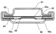
- valve 6 is formed by laminating a metal plate 65, a valve body 63, a PTC element 62, and a terminal cap 61 in a dish-shaped metal case 66.
- the sealing body shown in FIG. A central portion of the valve body 63 is welded to the metal plate 65, and an outer peripheral portion thereof is insulated from the metal plate 65 by an insulating gasket 64.
- the metal plate 65 and the metal case 66 have a vent hole 65a and a vent hole 66a, respectively.
- the welded portion is broken and the current path between the valve body 63 and the metal plate 65 is interrupted.
- the valve body 63 breaks starting from the thin portion 63a formed in the valve body 63, and the gas inside the battery is discharged to the outside of the battery.
- the current interruption mechanism and the explosion-proof valve provided in the sealing body operate as described above.
- the welded portion of the valve body and the metal plate functions as a current interrupting portion, but a thin portion provided on the metal plate as in Patent Documents 2 and 3 can also function as the current interrupting portion.
- the operating pressure of the current interruption mechanism depends on the breaking strength of the welded part or the thin part.
- JP-A-6-196150 Japanese Unexamined Patent Publication No. 7-105933 JP-A-9-147821 JP-A-9-199106
- the operating pressure of the current interrupt mechanism varies within a certain range.
- the variation in the operating pressure is large, there is a design limitation such as the setting value of the operating pressure having to be reduced in advance. Further, when the operating pressure varies greatly, the current interrupt mechanism may not operate stably. Therefore, a technique for reducing the variation in the operating pressure of the current interrupt mechanism is desired.
- Patent Document 3 discloses a result in which the variation in the operating pressure of the current interrupt mechanism is reduced by making the outer periphery of the valve body wavy.
- the technique according to Patent Document 3 prevents the occurrence of a defect in the assembly process of the sealing body in which the welded portion between the valve body and the metal plate is peeled off, and between the valve body and the metal plate after the operation of the current interrupting mechanism. The purpose of this is to reliably maintain the insulation state.
- Patent Document 3 describes that the variation in the operating pressure is reduced, but also describes that the operating pressure itself is increasing. Therefore, according to the technique according to Patent Document 3, there is a problem that it is difficult to reduce the variation in the operating pressure while maintaining the operating pressure.
- the present invention has been made in view of the above, and has been completed based on the knowledge that the valve body is stably deformed by providing an inclined region in which the thickness continuously changes in a part of the valve body. is there.
- a cylindrical battery includes an electrode body in which a positive electrode plate and a negative electrode plate are wound via a separator, an electrolyte, a bottomed cylindrical outer can, And a sealing body that is caulked and fixed to the opening of the outer can through a gasket.
- the sealing body is a valve body having a circular outer shape, a metal plate disposed on the inner side of the battery with respect to the valve body and connected to the central portion of the valve body, and between the outer periphery of the valve body and the outer periphery of the metal plate An annular insulating member interposed between the two is included.
- the valve body has an inclined region in which the thickness continuously decreases or increases along the radial direction.
- the valve body is stably deformed as the battery internal pressure increases, so that variation in the operating pressure of the current interrupt mechanism is reduced.
- FIG. 1 is a cross-sectional view of a cylindrical non-aqueous electrolyte secondary battery according to an embodiment of the present invention.
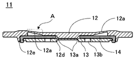
- FIG. 2 is a cross-sectional view of a sealing body according to an embodiment of the present invention.
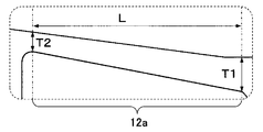
- FIG. 3 is an enlarged view of part A shown in FIG.
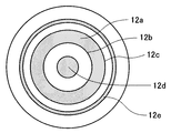
- FIG. 4 is a plan view of the sealing body according to the embodiment of the present invention as seen from the inside of the battery.
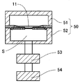
- FIG. 5 is a schematic view of an apparatus used for measuring the operating pressure.
- FIG. 6 is a cross-sectional view of a sealing body according to a conventional example.
- non-aqueous electrolyte secondary battery which is an example of a cylindrical battery.
- this invention is not limited to the following embodiment, In the range which does not change the summary, it can change suitably and can implement.
- a nonaqueous electrolyte secondary battery 10 shown in FIG. 1 contains an electrode body 18 and an electrolyte solution (not shown) inside a bottomed cylindrical outer can 22.
- the sealing body 11 is caulked and fixed to the opening of the outer can 22 via the gasket 21. Thereby, the inside of the battery is sealed.
- the sealing body 11 is comprised from the valve body 12, the metal plate 13, and the cyclic
- the valve body 12 and the metal plate 13 are connected to each other at the center, and an insulating member 14 is interposed between the outer periphery of the valve body 12 and the outer periphery of the metal plate 13.
- the valve body 12 arranged at the outermost part of the sealing body 11 functions as an external terminal, and the metal plate 13 connected to the positive electrode lead 15a led out from the electrode body 18 functions as an internal terminal.
- the sealing body 11 having the above-described configuration has an advantage of excellent gas discharge capability inside the battery when the valve body 12 is broken.
- the current interruption mechanism operates as follows.
- the metal plate 13 is provided with a vent hole 13b.
- the valve body 12 receives the pressure. Therefore, the valve body 12 acts so as to pull the connection portion with the metal plate 13 to the outside of the battery as the battery internal pressure increases.
- the thin portion 13a as the easily breakable portion provided around the welded portion of the metal plate 13 with the valve body 12 breaks, and the current between the valve body 12 and the metal plate 13 is broken.
- the route is interrupted. That is, if the sealing body 11 includes three members, that is, the valve body 12, the metal plate 13, and the annular insulating member 14, a current interruption mechanism can be configured.
- the metal plate 13 does not have a thin part, although the welding part of the metal plate 13 and the valve body 12 can be made into an electric current interruption part, it is preferable to form the thin part 13a in the metal plate 13. FIG. This is because it is easier to adjust the breaking strength of the thin-walled portion than the breaking strength of the welded portion.
- the thin portion 13a is preferably formed around the welded portion of the metal plate 13 with the valve body 12, and the cross-sectional shape of the thin portion 13a is preferably V-shaped or U-shaped.
- the valve body 12 can be produced by pressing a plate of aluminum or aluminum alloy.
- the outer shape of the valve body 12 in plan view is circular.
- on the inner surface of the battery body 12 is an inclined region 12a where the thickness continuously decreases along the radial direction from the inner peripheral portion to the outer peripheral portion, and a protrusion 12d at the central portion.
- a protrusion 12e on the outer periphery is an inclined region 12a where the thickness continuously decreases along the radial direction from the inner peripheral portion to the outer peripheral portion.
- a protrusion 12e on the outer periphery The central protrusion 12 d facilitates connection to the metal plate 13 and forms a space for interposing the insulating member 14 between the outer periphery of the valve body 12 and the outer periphery of the metal plate 13.
- the protrusion 12 e on the outer peripheral portion can fix the metal plate 13 via the insulating member 14.
- the configuration of the present embodiment is preferable because the valve body 12 can be deformed more stably. Note that “the thickness of the valve body continuously decreases or increases” does not require that the rate of change of the thickness of the valve body in the inclined region 12a is constant over the entire range.
- the inclined region 12a is formed so as to occupy a region surrounded by the concentric circle 12b on the inner peripheral side and the concentric circle 12c on the outer peripheral side of the outer shape of the valve body 12.
- L is the radius of the valve body 12. It is preferably 10% or more and 90% or less. In this embodiment, since L is equal in any part, the valve body 12 can be stably deformed as the battery internal pressure increases.
- the valve body 12 can be formed with a groove-like thin portion. Thereby, the valve body 12 operates more stably as an explosion-proof valve.
- the thin portion may be formed inside the inclined region 12a.
- the cross-sectional shape of the thin wall portion is preferably V-shaped or U-shaped.
- the metal plate 13 can be made from a plate material of aluminum or aluminum alloy.
- the metal plate 13 is provided with a vent hole 13b. Laser welding is exemplified as a method for connecting the metal plate 13 to the valve body 12.
- the insulating member 14 can be made of a material that can ensure insulation between the valve body 12 and the metal plate 13 and does not affect battery characteristics.
- the material used for the insulating member 14 is preferably a polymer resin, and examples thereof include polypropylene (PP) resin and polybutylene terephthalate (PBT) resin.
- the sealing body 11 includes the valve body 12, the metal plate 13, and the insulating member 14 is used.
- the sealing body can include other members. Examples of other members include a terminal cap and a PTC element.
- the terminal cap functions as an external terminal instead of the valve body 12 by being arranged on the battery outer side of the valve body 12.
- the metal plate 13 functions as an internal terminal. However, by disposing another metal plate inside the battery of the metal plate 13, the other metal plate functions as an internal terminal.
- an electrode body 18 formed by winding a positive electrode plate 15 and a negative electrode plate 16 via a separator 17 is used.
- the positive electrode plate 15 can be manufactured, for example, as follows. First, the positive electrode active material and the binder are kneaded uniformly in the dispersion medium to prepare a positive electrode mixture slurry. It is preferable to use polyvinylidene fluoride as the binder and N-methylpyrrolidone as the dispersion medium. It is preferable to add a conductive agent such as graphite or carbon black to the positive electrode mixture slurry. This positive electrode mixture slurry is applied on a positive electrode current collector and dried to form a positive electrode mixture layer. In that case, the positive electrode collector exposed part in which the positive mix layer is not formed in a part of the positive electrode collector is provided. Next, the positive electrode mixture layer is compressed to a predetermined thickness with a roller, and the compressed electrode plate is cut into a predetermined dimension. Finally, the positive electrode lead 15a is connected to the exposed portion of the positive electrode current collector.
- a lithium transition metal composite oxide capable of inserting and extracting lithium ions can be used.
- the lithium transition metal composite oxide include general formula LiMO 2 (M is at least one of Co, Ni, and Mn), LiMn 2 O 4, and LiFePO 4 . These can be used singly or in combination of two or more, and used by adding at least one selected from the group consisting of Al, Ti, Mg, and Zr, or replacing a transition metal element. Can do.
- the negative electrode plate 16 can be produced, for example, as follows. First, a negative electrode active material and a binder are kneaded so as to be uniform in a dispersion medium to prepare a negative electrode mixture slurry. It is preferable to use styrene butadiene (SBR) copolymer or polyvinylidene fluoride (PVdF) as the binder and water as the dispersion medium. It is preferable to add a thickener such as carboxymethylcellulose to the negative electrode mixture slurry. This negative electrode mixture slurry is applied onto a negative electrode current collector and dried to form a negative electrode mixture layer.
- SBR styrene butadiene
- PVdF polyvinylidene fluoride
- the negative electrode collector exposure part in which the negative mix layer is not formed in a part of negative electrode collector is provided.
- the negative electrode mixture layer is compressed to a predetermined thickness with a roller, and the compressed electrode plate is cut into a predetermined dimension.
- the negative electrode lead 16a is connected to the negative electrode current collector exposed portion.
- a carbon material or a metal material capable of inserting and extracting lithium ions can be used as the negative electrode active material.
- the carbon material include graphite such as natural graphite and artificial graphite.
- the metal material include silicon and tin, and oxides thereof. The carbon material and the metal material can be used alone or in admixture of two or more.
- a microporous film mainly composed of polyolefin such as polyethylene (PE) or polypropylene (PP) can be used.
- the microporous membrane can be used singly or as a laminate of two or more layers.
- a layer mainly composed of polyethylene (PE) having a low melting point is used as an intermediate layer and polypropylene (PP) having excellent oxidation resistance is used as a surface layer.
- inorganic particles such as aluminum oxide (Al 2 O 3 ), titanium oxide (TiO 2 ), and silicon oxide (SiO 2 ) can be added to the separator. Such inorganic particles can be carried in the separator and can be applied together with a binder on the separator surface.
- non-aqueous electrolyte a solution obtained by dissolving a lithium salt as an electrolyte salt in a non-aqueous solvent can be used.
- a cyclic carbonate, a chain carbonate, a cyclic carboxylic acid ester and a chain carboxylic acid ester can be used, and it is preferable to use a mixture of two or more.
- the cyclic carbonate include ethylene carbonate (EC), propylene carbonate (PC), and butylene carbonate (BC).
- a cyclic carbonate in which part of hydrogen is substituted with fluorine, such as fluoroethylene carbonate (FEC) can also be used.
- the chain carbonate include dimethyl carbonate (DMC), ethyl methyl carbonate (EMC), diethyl carbonate (DEC), and methyl propyl carbonate (MPC).
- Examples of cyclic carboxylic acid esters include ⁇ -butyrolactone ( ⁇ -BL) and ⁇ -valerolactone ( ⁇ -VL).
- Examples of chain carboxylic acid esters include methyl pivalate, ethyl pivalate, methyl isobutyrate and methyl Pionate is exemplified.
- LiPF 6 , LiBF 4 , LiCF 3 SO 3 , LiN (CF 3 SO 2 ) 2 , LiN (C 2 F 5 SO 2 ) 2 , LiN (CF 3 SO 2 ) (C 4 F 9 SO 2 ) , LiC (CF 3 SO 2 ) 3 , LiC (C 2 F 5 SO 2 ) 3 , LiAsF 6 , LiClO 4 , Li 2 B 10 Cl 10 and Li 2 B 12 Cl 12 are exemplified.
- LiPF 6 is particularly preferable, and the concentration in the nonaqueous electrolytic solution is preferably 0.5 to 2.0 mol / L.
- Other lithium salts such as LiBF 4 may be mixed with LiPF 6 .
- Example 1 Preparation of sealing body
- the valve body 12 and the metal plate 13 were produced by pressing a plate material made of aluminum.
- the radii of the inner circumference side concentric circle 12b and the outer circumference side concentric circle 12c of the outer shape of the valve body 12 constituting the end of the inclined region 12a were 7 mm and 12 mm, respectively.
- the inclined region is set such that T1 and T2 are 0.3 mm and 0.2 mm, respectively. 12a was formed.
- the annular insulating member 14 interposed between the outer peripheral portion of the valve body 12 and the outer peripheral portion of the metal plate 13, the central portion of the valve body 12 and the metal plate 13 is connected to form the sealing body 11 shown in FIG. Produced.
- the positive electrode mixture layer was compressed to a predetermined thickness with a roller, and the compressed electrode plate was cut into predetermined dimensions.
- a positive electrode plate 15 was fabricated by connecting an aluminum positive electrode lead 15a to the exposed portion of the positive electrode current collector by ultrasonic welding.
- the negative electrode mixture layer was compressed with a roller to a predetermined thickness, and the compressed electrode plate was cut into a predetermined dimension. Finally, a negative electrode lead 16a made of nickel was connected to the exposed portion of the negative electrode current collector by ultrasonic welding to produce a negative electrode plate 16.
- Ethylene carbonate (EC), dimethyl carbonate (DMC), and ethyl methyl carbonate (EMC) were mixed to prepare a non-aqueous solvent.
- LiPF 6 lithium hexafluorophosphate
- this non-aqueous solvent lithium hexafluorophosphate (LiPF 6 ) as an electrolyte salt was dissolved to a concentration of 1 mol / L to prepare a non-aqueous electrolyte.
- the positive electrode plate 15 and the negative electrode plate 16 produced as described above were wound through a separator 17 made of a microporous polyolefin film to produce an electrode body 18.
- a lower insulating plate 19 is disposed below the electrode body 18, and the electrode body 18 is inserted into a bottomed cylindrical outer can 22.
- the negative electrode lead 16a was connected to the bottom of the outer can 22 by resistance welding.
- the upper insulating plate 20 is disposed on the upper portion of the electrode body 18, and a U-shaped groove portion having a width of 1.0 mm and a depth of 1.5 mm is formed in the circumferential direction by plastic working in the vicinity of the opening of the outer can 22. Formed.
- the positive electrode lead 15 a was connected to the metal plate 13 by laser welding, and the sealing body 11 was caulked and fixed to the groove formed in the outer can 22 via the gasket 21 to produce the nonaqueous electrolyte secondary battery 10. .
- Example 2 and 3 The nonaqueous electrolyte secondary battery 10 according to Examples 2 and 3 was produced in the same manner as in Example 1 except that the thickness T2 of the end on the outer peripheral side of the inclined region 12a was changed to the value described in Table 1. did.
- Example 1 Comparative Example 1 Except that the valve body was produced so that the thickness of the valve body in the region corresponding to the inclined region 12a in Example 1 was 0.2 mm (equal to T2 in Example 1), the same as in Example 1. A non-aqueous electrolyte secondary battery according to Comparative Example 1 was produced.
- Comparative Example 2 In the same manner as in Example 2 except that the valve body was manufactured so that the thickness of the valve body in the region corresponding to the inclined region 12a in Example 2 was uniform at 0.195 mm (equal to T2 in Example 2). A non-aqueous electrolyte secondary battery according to Comparative Example 2 was produced.
- Example 3 is the same as Example 3 except that the valve body is made uniform so that the thickness of the valve body in the region corresponding to the inclined region 12a in Example 3 is 0.205 mm (equal to T2 in Example 3). A nonaqueous electrolyte secondary battery according to Comparative Example 3 was produced.
- the sealing body was fixed to a fixing jig 50 having a pressing part 51 and a receiving part 52.
- the receiving part 52 is fixed to a part of the measuring device, and the airtightness of the space S surrounded by the sealing body and the receiving part 52 is secured by pressing the pressing part 51 from above with an air cylinder.
- Nitrogen gas was supplied at a constant speed via a regulator 53 from a gas cylinder 54 in which the space S was filled with nitrogen gas.
- the pressure in the space S at the time when the current path between the valve body and the metal plate was interrupted during the supply of nitrogen gas was used as the operating pressure of the current interrupting mechanism of the sealing body.
- the process capability index (Cpk) as an index of the variation in the working pressure was calculated for each of Examples 1 to 3 and Comparative Examples 1 to 3 from the working pressure thus measured.
- the process capability index is a value obtained by dividing the difference between the standard value of the working pressure and the value close to the standard value among the upper limit value and the lower limit value of the working pressure by 3 ⁇ ⁇ (standard deviation). Table 1 summarizes the results.
- the valve body of Comparative Example 1 has a configuration in which the valve body thickness in the inclined region of Example 1 is made uniform at T2 which is the minimum thickness. Since the thickness of the valve body is thinner in Comparative Example 1 than in Example 1, the valve body is more likely to be deformed in Comparative Example 1 than in Example 1.
- the working pressure variation is greatly reduced in the first embodiment in which the inclined region is provided. This indicates that when the valve body is provided with an inclined region as in the first embodiment, the minimum thickness portion becomes the starting point of the deformation of the valve body, and individual differences are less likely to occur in the deformation behavior of the valve body. Similar results were obtained by comparison between Example 2 and Comparative Example 2, and Example 3 and Comparative Example 3. That is, the effect of the present invention is exhibited by the inclined region.
- the inclined regions in Examples 1 to 3 were formed so that the thickness of the valve body continuously decreased along the radial direction from the inner peripheral portion to the outer peripheral portion of the valve body.
- the innermost peripheral portion of the inclined region is the starting point of deformation of the valve body. Therefore, the effect of the present invention is considered to be exhibited similarly.
- this invention is applicable also to cylindrical batteries other than a non-aqueous electrolyte secondary battery, such as a nickel hydride battery. it can.
- the present invention since the operating pressure variation of the current interrupt mechanism can be reduced, a cylindrical battery excellent in safety can be provided.
- the present invention is suitable for applications using a high energy density cylindrical battery.
- Such applications include small electronic devices such as notebook computers, power tools such as electric tools and electric assist bicycles, and drive power sources such as electric vehicles.
Landscapes
- Chemical & Material Sciences (AREA)
- Chemical Kinetics & Catalysis (AREA)
- Electrochemistry (AREA)
- General Chemical & Material Sciences (AREA)
- Engineering & Computer Science (AREA)
- Manufacturing & Machinery (AREA)
- Gas Exhaust Devices For Batteries (AREA)
- Secondary Cells (AREA)
- Sealing Battery Cases Or Jackets (AREA)
- Connection Of Batteries Or Terminals (AREA)
Abstract
Description
(封口体の作製)
弁体12及び金属板13はアルミニウムからなる板材をプレス加工することによって作製した。傾斜領域12aの端部を構成する弁体12の外形の内周側の同心円12b及び外周側の同心円12cの半径はそれぞれ7mm及び12mmとした。また、図3に示すように傾斜領域12aの内周側及び外周側のそれぞれの厚みをT1及びT2としたときに、そのT1及びT2がそれぞれ0.3mm及び0.2mmになるように傾斜領域12aを形成した。弁体12の外周部と金属板13の外周部の間に環状の絶縁部材14を介在させた状態で、弁体12と金属板13の中央部を接続して図2に示す封口体11を作製した。
正極活物質としてのLiNi0.8Co0.15Al0.05O2が100質量部、結着剤としてのポリフッ化ビニリデン(PVdF)が1.7質量部、導電剤としてのアセチレンブラックが2.5重量部となるように分散媒中に投入、混練して正極合剤スラリーを調製した。この正極合剤スラリーをアルミニウム箔からなる正極集電体の両面に塗布、乾燥して正極合剤層を形成した。その際、正極集電体の一部に正極合剤層が形成されていない正極集電体露出部を設けた。次に、正極合剤層をローラーで所定厚みに圧縮し、圧縮後の極板を所定寸法に切断した。最後に、正極集電体露出部にアルミニウム製の正極リード15aを超音波溶着により接続して正極板15を作製した。
負極活物質としての黒鉛が100質量部、結着剤としてのポリフッ化ビニリデン(PVdF)が0.6質量部、増粘剤としてのカルボキシメチルセルロース(CMC)が1重量部となるように分散媒中に投入、混練して負極合剤スラリーを調製した。この負極合剤スラリーを銅箔からなる負極集電体の両面に塗布、乾燥して負極合剤層を形成した。その際、負極集電体の一部に負極合剤層が形成されていない負極集電体露出部を設けた。次に、負極合剤層をローラーで所定厚みに圧縮し、圧縮後の極板を所定寸法に切断した。最後に、負極集電体露出部にニッケル製の負極リード16aを超音波溶着により接続して負極板16を作製した。
エチレンカーボネート(EC)、ジメチルカーボネート(DMC)、及びエチルメチルカーボネート(EMC)を混合して非水溶媒を調製した。この非水溶媒に電解質塩としてのヘキサフルオロリン酸リチウム(LiPF6)を1mol/Lの濃度になるように溶解して非水電解液を調製した。
上記のようにして作製した正極板15と負極板16を、微多孔製ポリオレフィン膜からなるセパレータ17を介して巻回して電極体18を作製した。
図1に示すように、電極体18の下部に下部絶縁板19を配置し、電極体18を有底円筒状の外装缶22へ挿入した。負極リード16aは外装缶22の底部に抵抗溶接により接続した。次に、電極体18の上部に上部絶縁板20を配置し、外装缶22の開口部の近傍に幅1.0mm、深さ1.5mmのU字状の溝部を円周方向に塑性加工によって形成した。そして、正極リード15aを金属板13とレーザー溶接により接続し、外装缶22に形成された溝部にガスケット21を介して封口体11をかしめ固定することにより非水電解液二次電池10を作製した。
傾斜領域12aの外周側の端部の厚みT2を表1に記載された値に変更したこと以外は実施例1と同様にして実施例2及び3に係る非水電解液二次電池10を作製した。
実施例1における傾斜領域12aに対応する領域の弁体の厚みが0.2mm(実施例1のT2に等しい)で均一になるように弁体を作製したこと以外は実施例1と同様にして比較例1に係る非水電解液二次電池を作製した。
実施例2における傾斜領域12aに対応する領域の弁体の厚みが0.195mm(実施例2のT2に等しい)で均一になるように弁体を作製したこと以外は実施例2と同様にして比較例2に係る非水電解液二次電池を作製した。
実施例3における傾斜領域12aに対応する領域の弁体の厚みが0.205mm(実施例3のT2に等しい)で均一になるように弁体を作製したこと以外は実施例3と同様にして比較例3に係る非水電解液二次電池を作製した。
実施例1~3及び比較例1~3のそれぞれ10個の電池を用意し、充電深度が30%になるように各電池を充電した。充電された電池から封口体を取り出した後、封口体の電流遮断機構の作動圧を測定した。作動圧の測定は以下のように行った。

11 封口体
12 弁体
12a 傾斜領域
12b 弁体の外形の内周側の同心円
12c 弁体の外形の外周側の同心円
12e 外周部の突起部
13 金属板
13a 薄肉部
14 絶縁部材
15 正極板
16 負極板
17 セパレータ
18 電極体
22 外装缶
Claims (8)
- 正極板と負極板がセパレータを介して巻回された電極体と、電解液と、有底円筒状の外装缶と、前記外装缶の開口部にガスケットを介してかしめ固定された封口体と、を備え、
前記封口体が、外形が円形の弁体、前記弁体よりも電池内方側に配置されるとともに前記弁体の中央部に接続された金属板、及び前記弁体の外周部と前記金属板の外周部の間に介在する環状の絶縁部材、を含み、
前記弁体が内周部から外周部へ半径方向に沿って厚みが連続的に減少する傾斜領域を有する、
円筒形電池。 - 正極板と負極板がセパレータを介して巻回された電極体と、電解液と、有底円筒状の外装缶と、前記外装缶の開口部にガスケットを介してかしめ固定された封口体と、を備え、
前記封口体が、外形が円形の弁体、前記弁体よりも電池内方側に配置されるとともに前記弁体の中央部に接続された金属板、並びに前記弁体及び前記金属板のそれぞれの外周部の間に介在する環状の絶縁部材、を含み、
前記弁体が内周部から外周部へ半径方向に沿って厚みが連続的に増加する傾斜領域を有する、
円筒形電池。 - 前記傾斜領域の前記弁体の半径方向に沿った長さは前記弁体の半径の10%以上90%以下である請求項1又は2に記載の円筒形電池。
- 前記傾斜領域が前記弁体の外形の二つの同心円に囲まれる領域を占めている請求項1から3のいずれかに記載の円筒形電池。
- 前記弁体は溝状の薄肉部を有する請求項1から4のいずれかに記載の円筒形電池。
- 前記金属板は前記電極体とリードを介して電気的に接続されている請求項1から5のいずれかに記載の円筒形電池。
- 前記弁体は前記封口体の最外部に配置されている請求項1から6のいずれかに記載の円筒形電池。
- 前記金属板は、前記弁体との溶接部の周囲に溝状の薄肉部を有する請求項1から7のいずれかに記載の円筒形電池。
Priority Applications (3)
| Application Number | Priority Date | Filing Date | Title |
|---|---|---|---|
| US15/554,947 US10615401B2 (en) | 2015-03-27 | 2016-03-10 | Cylindrical batteries |
| CN201680014383.5A CN107431178B (zh) | 2015-03-27 | 2016-03-10 | 圆筒形电池 |
| JP2017509231A JP6662377B2 (ja) | 2015-03-27 | 2016-03-10 | 円筒形電池 |
Applications Claiming Priority (2)
| Application Number | Priority Date | Filing Date | Title |
|---|---|---|---|
| JP2015066234 | 2015-03-27 | ||
| JP2015-066234 | 2015-03-27 |
Publications (1)
| Publication Number | Publication Date |
|---|---|
| WO2016157749A1 true WO2016157749A1 (ja) | 2016-10-06 |
Family
ID=57006853
Family Applications (1)
| Application Number | Title | Priority Date | Filing Date |
|---|---|---|---|
| PCT/JP2016/001339 Ceased WO2016157749A1 (ja) | 2015-03-27 | 2016-03-10 | 円筒形電池 |
Country Status (4)
| Country | Link |
|---|---|
| US (1) | US10615401B2 (ja) |
| JP (1) | JP6662377B2 (ja) |
| CN (1) | CN107431178B (ja) |
| WO (1) | WO2016157749A1 (ja) |
Cited By (21)
| Publication number | Priority date | Publication date | Assignee | Title |
|---|---|---|---|---|
| JP2019519078A (ja) * | 2016-06-23 | 2019-07-04 | テスラ,インコーポレイテッド | 溶接電池キャップを有する電池セル |
| CN110226248A (zh) * | 2017-03-27 | 2019-09-10 | 松下电器产业株式会社 | 二次电池用绝缘板及具备该二次电池用绝缘板的二次电池 |
| CN111194491A (zh) * | 2017-10-23 | 2020-05-22 | 三洋电机株式会社 | 圆筒形电池 |
| WO2020129480A1 (ja) | 2018-12-21 | 2020-06-25 | 三洋電機株式会社 | 密閉電池 |
| WO2020137373A1 (ja) * | 2018-12-27 | 2020-07-02 | 三洋電機株式会社 | 円筒形電池 |
| WO2021153439A1 (ja) | 2020-01-31 | 2021-08-05 | パナソニックIpマネジメント株式会社 | 蓄電装置 |
| WO2021166631A1 (ja) | 2020-02-19 | 2021-08-26 | 三洋電機株式会社 | 円筒形電池 |
| WO2021172235A1 (ja) | 2020-02-28 | 2021-09-02 | パナソニックIpマネジメント株式会社 | 蓄電デバイス |
| WO2021187045A1 (ja) | 2020-03-16 | 2021-09-23 | 三洋電機株式会社 | 円筒形電池 |
| WO2021200440A1 (ja) | 2020-03-31 | 2021-10-07 | 三洋電機株式会社 | 円筒形電池 |
| WO2021200439A1 (ja) | 2020-03-30 | 2021-10-07 | 三洋電機株式会社 | 円筒形電池 |
| US11316223B2 (en) | 2017-07-31 | 2022-04-26 | Panasonic Intellectual Property Management Co., Ltd. | Cylindrical battery |
| WO2022158378A1 (ja) | 2021-01-21 | 2022-07-28 | 三洋電機株式会社 | 円筒形電池 |
| WO2022181338A1 (ja) | 2021-02-26 | 2022-09-01 | 三洋電機株式会社 | 円筒形電池 |
| JP2023513117A (ja) * | 2020-04-06 | 2023-03-30 | エルジー エナジー ソリューション リミテッド | 二次電池およびこれを含むデバイス |
| JP2023077815A (ja) * | 2021-11-25 | 2023-06-06 | 三洋電機株式会社 | 電池 |
| WO2023153194A1 (ja) | 2022-02-09 | 2023-08-17 | パナソニックエナジー株式会社 | 円筒形電池およびその製造方法 |
| US11757153B2 (en) | 2017-07-31 | 2023-09-12 | Panasonic Intellectual Property Management Co., Ltd. | Cylindrical battery |
| US11831032B2 (en) | 2017-07-31 | 2023-11-28 | Panasonic Intellectual Property Management Co., Ltd. | Cylindrical battery |
| WO2024042918A1 (ja) | 2022-08-23 | 2024-02-29 | パナソニックIpマネジメント株式会社 | 非水電解質二次電池 |
| WO2025094549A1 (ja) | 2023-10-31 | 2025-05-08 | パナソニックIpマネジメント株式会社 | 二次電池および二次電池の製造方法 |
Families Citing this family (9)
| Publication number | Priority date | Publication date | Assignee | Title |
|---|---|---|---|---|
| CN106816573A (zh) * | 2017-03-23 | 2017-06-09 | 惠州亿纬锂能股份有限公司 | 一种电池及电池组件 |
| JP7379380B2 (ja) * | 2018-12-28 | 2023-11-14 | パナソニックエナジー株式会社 | 密閉電池 |
| JP7432881B2 (ja) * | 2018-12-28 | 2024-02-19 | パナソニックIpマネジメント株式会社 | 電池 |
| US12424688B2 (en) * | 2018-12-28 | 2025-09-23 | Panasonic Energy Co., Ltd. | Cylindrical battery |
| FR3095898B1 (fr) * | 2019-05-06 | 2021-04-16 | Commissariat Energie Atomique | Procédé et système de caractérisation mécanique du godet d'une batterie |
| WO2022158164A1 (ja) * | 2021-01-19 | 2022-07-28 | Fdk株式会社 | 円筒形蓄電池用の封口体、及び、当該封口体を用いた円筒形蓄電池 |
| EP4318768A4 (en) * | 2021-03-25 | 2025-05-21 | Panasonic Energy Co., Ltd. | SEALED BATTERY |
| KR102854045B1 (ko) * | 2021-08-31 | 2025-09-01 | 엘에스머트리얼즈 주식회사 | 전기이중층 커패시터 |
| CN114497795A (zh) * | 2022-02-07 | 2022-05-13 | 沈明东 | 二次电池再生方法 |
Citations (4)
| Publication number | Priority date | Publication date | Assignee | Title |
|---|---|---|---|---|
| JP2000149919A (ja) * | 1998-11-10 | 2000-05-30 | Samsung Sdi Co Ltd | 二次電池の安全装置 |
| US20100291422A1 (en) * | 2009-05-15 | 2010-11-18 | Dongguan Amperex Technology Limited | Cap assembly for use in lithium ion batteries |
| JP2010272389A (ja) * | 2009-05-22 | 2010-12-02 | Toyota Motor Corp | 密閉型電池 |
| JP2011150966A (ja) * | 2010-01-25 | 2011-08-04 | Hitachi Vehicle Energy Ltd | 密閉型電池およびその製造方法 |
Family Cites Families (15)
| Publication number | Priority date | Publication date | Assignee | Title |
|---|---|---|---|---|
| US4803136A (en) * | 1985-09-30 | 1989-02-07 | Emerson Electric Co. | Method of manufacturing a safety vented container and product |
| CA2099657C (en) | 1992-08-10 | 1998-04-07 | Alexander H. Rivers-Bowerman | Electrochemical cell and method of manufacturing same |
| JPH07105933A (ja) | 1993-10-06 | 1995-04-21 | Hitachi Maxell Ltd | 防爆形密閉電池 |
| US5741606A (en) * | 1995-07-31 | 1998-04-21 | Polystor Corporation | Overcharge protection battery vent |
| CA2240415C (en) * | 1995-10-31 | 2002-12-24 | Matsushita Electric Industrial Co., Ltd. | Explosion-proof seal plate for sealed type cell and production method thereof |
| JP3168892B2 (ja) | 1995-11-29 | 2001-05-21 | 松下電器産業株式会社 | 二次電池用防爆封口板 |
| JPH09199106A (ja) | 1996-01-19 | 1997-07-31 | Matsushita Electric Ind Co Ltd | 2次電池用防爆封口板 |
| US5853912A (en) * | 1996-07-10 | 1998-12-29 | Saft America, Inc. | Lithium ion electrochemical cell with safety valve electrical disconnect |
| US6730430B2 (en) * | 2001-07-09 | 2004-05-04 | Nan Ya Plastics Corporation | Explosion-proof safety structure for column shape lithium battery |
| JP5011664B2 (ja) * | 2005-07-11 | 2012-08-29 | パナソニック株式会社 | 密閉型二次電池 |
| KR100912789B1 (ko) * | 2006-09-11 | 2009-08-18 | 주식회사 엘지화학 | 안전성이 향상된 원통형 이차전지 |
| JP5893935B2 (ja) * | 2012-01-27 | 2016-03-23 | トヨタ自動車株式会社 | 密閉型電池 |
| JP5788815B2 (ja) * | 2012-01-27 | 2015-10-07 | 三洋電機株式会社 | 角形二次電池 |
| CN105849940B (zh) * | 2013-12-25 | 2018-09-25 | 日立汽车系统株式会社 | 方形二次电池 |
| JP6565873B2 (ja) * | 2016-11-21 | 2019-08-28 | トヨタ自動車株式会社 | 密閉型電池 |
-
2016
- 2016-03-10 US US15/554,947 patent/US10615401B2/en active Active
- 2016-03-10 CN CN201680014383.5A patent/CN107431178B/zh active Active
- 2016-03-10 WO PCT/JP2016/001339 patent/WO2016157749A1/ja not_active Ceased
- 2016-03-10 JP JP2017509231A patent/JP6662377B2/ja active Active
Patent Citations (4)
| Publication number | Priority date | Publication date | Assignee | Title |
|---|---|---|---|---|
| JP2000149919A (ja) * | 1998-11-10 | 2000-05-30 | Samsung Sdi Co Ltd | 二次電池の安全装置 |
| US20100291422A1 (en) * | 2009-05-15 | 2010-11-18 | Dongguan Amperex Technology Limited | Cap assembly for use in lithium ion batteries |
| JP2010272389A (ja) * | 2009-05-22 | 2010-12-02 | Toyota Motor Corp | 密閉型電池 |
| JP2011150966A (ja) * | 2010-01-25 | 2011-08-04 | Hitachi Vehicle Energy Ltd | 密閉型電池およびその製造方法 |
Cited By (40)
| Publication number | Priority date | Publication date | Assignee | Title |
|---|---|---|---|---|
| US11495854B2 (en) | 2016-06-23 | 2022-11-08 | Tesla, Inc. | Battery cell having welded battery cap |
| JP2019519078A (ja) * | 2016-06-23 | 2019-07-04 | テスラ,インコーポレイテッド | 溶接電池キャップを有する電池セル |
| US11942591B2 (en) | 2016-06-23 | 2024-03-26 | Tesla, Inc. | Battery cell having welded battery cap |
| JP7018903B2 (ja) | 2016-06-23 | 2022-02-14 | テスラ,インコーポレイテッド | 溶接電池キャップを有する電池セル |
| US11901501B2 (en) | 2017-03-27 | 2024-02-13 | Panasonic Holdings Corporation | Secondary battery insulating plate and secondary battery including the same |
| CN110226248A (zh) * | 2017-03-27 | 2019-09-10 | 松下电器产业株式会社 | 二次电池用绝缘板及具备该二次电池用绝缘板的二次电池 |
| US11495855B2 (en) | 2017-03-27 | 2022-11-08 | Panasonic Holdings Corporation | Secondary battery insulating plate and secondary battery including the same |
| US11757153B2 (en) | 2017-07-31 | 2023-09-12 | Panasonic Intellectual Property Management Co., Ltd. | Cylindrical battery |
| US11316223B2 (en) | 2017-07-31 | 2022-04-26 | Panasonic Intellectual Property Management Co., Ltd. | Cylindrical battery |
| US11831032B2 (en) | 2017-07-31 | 2023-11-28 | Panasonic Intellectual Property Management Co., Ltd. | Cylindrical battery |
| JPWO2019082711A1 (ja) * | 2017-10-23 | 2020-11-12 | 三洋電機株式会社 | 円筒形電池 |
| JP7225110B2 (ja) | 2017-10-23 | 2023-02-20 | 三洋電機株式会社 | 円筒形電池 |
| CN111194491A (zh) * | 2017-10-23 | 2020-05-22 | 三洋电机株式会社 | 圆筒形电池 |
| WO2020129480A1 (ja) | 2018-12-21 | 2020-06-25 | 三洋電機株式会社 | 密閉電池 |
| US12176567B2 (en) | 2018-12-21 | 2024-12-24 | Panasonic Energy Co., Ltd. | Sealed battery |
| JPWO2020137373A1 (ja) * | 2018-12-27 | 2021-11-18 | 三洋電機株式会社 | 円筒形電池 |
| JP7410880B2 (ja) | 2018-12-27 | 2024-01-10 | パナソニックエナジー株式会社 | 円筒形電池 |
| US12224445B2 (en) | 2018-12-27 | 2025-02-11 | Panasonic Energy Co., Ltd. | Cylindrical battery |
| WO2020137373A1 (ja) * | 2018-12-27 | 2020-07-02 | 三洋電機株式会社 | 円筒形電池 |
| US12548868B2 (en) | 2020-01-31 | 2026-02-10 | Panasonic Intellectual Property Management Co., Ltd. | Power storage device |
| WO2021153439A1 (ja) | 2020-01-31 | 2021-08-05 | パナソニックIpマネジメント株式会社 | 蓄電装置 |
| US12463235B2 (en) | 2020-02-19 | 2025-11-04 | Panasonic Energy Co., Ltd. | Cylindrical battery |
| WO2021166631A1 (ja) | 2020-02-19 | 2021-08-26 | 三洋電機株式会社 | 円筒形電池 |
| US12444790B2 (en) | 2020-02-28 | 2025-10-14 | Panasonic Intellectual Property Management Co., Ltd. | Electricity storage device |
| WO2021172235A1 (ja) | 2020-02-28 | 2021-09-02 | パナソニックIpマネジメント株式会社 | 蓄電デバイス |
| WO2021187045A1 (ja) | 2020-03-16 | 2021-09-23 | 三洋電機株式会社 | 円筒形電池 |
| WO2021200439A1 (ja) | 2020-03-30 | 2021-10-07 | 三洋電機株式会社 | 円筒形電池 |
| WO2021200440A1 (ja) | 2020-03-31 | 2021-10-07 | 三洋電機株式会社 | 円筒形電池 |
| CN115336088A (zh) * | 2020-03-31 | 2022-11-11 | 三洋电机株式会社 | 圆筒形电池 |
| JP2023513117A (ja) * | 2020-04-06 | 2023-03-30 | エルジー エナジー ソリューション リミテッド | 二次電池およびこれを含むデバイス |
| JP7779000B2 (ja) | 2020-04-06 | 2025-12-03 | エルジー エナジー ソリューション リミテッド | 二次電池およびこれを含むデバイス |
| JPWO2022158378A1 (ja) * | 2021-01-21 | 2022-07-28 | ||
| WO2022158378A1 (ja) | 2021-01-21 | 2022-07-28 | 三洋電機株式会社 | 円筒形電池 |
| JP7818534B2 (ja) | 2021-01-21 | 2026-02-20 | パナソニックエナジー株式会社 | 円筒形電池 |
| WO2022181338A1 (ja) | 2021-02-26 | 2022-09-01 | 三洋電機株式会社 | 円筒形電池 |
| JP2023077815A (ja) * | 2021-11-25 | 2023-06-06 | 三洋電機株式会社 | 電池 |
| JP7816953B2 (ja) | 2021-11-25 | 2026-02-18 | パナソニックエナジー株式会社 | 電池 |
| WO2023153194A1 (ja) | 2022-02-09 | 2023-08-17 | パナソニックエナジー株式会社 | 円筒形電池およびその製造方法 |
| WO2024042918A1 (ja) | 2022-08-23 | 2024-02-29 | パナソニックIpマネジメント株式会社 | 非水電解質二次電池 |
| WO2025094549A1 (ja) | 2023-10-31 | 2025-05-08 | パナソニックIpマネジメント株式会社 | 二次電池および二次電池の製造方法 |
Also Published As
| Publication number | Publication date |
|---|---|
| JP6662377B2 (ja) | 2020-03-11 |
| JPWO2016157749A1 (ja) | 2018-01-18 |
| CN107431178A (zh) | 2017-12-01 |
| US10615401B2 (en) | 2020-04-07 |
| CN107431178B (zh) | 2020-08-11 |
| US20180047973A1 (en) | 2018-02-15 |
Similar Documents
| Publication | Publication Date | Title |
|---|---|---|
| JP6662377B2 (ja) | 円筒形電池 | |
| CN107431179B (zh) | 圆筒形电池 | |
| US10461304B2 (en) | Cylindrical battery | |
| JP6490053B2 (ja) | 円筒形密閉電池及び電池パック | |
| CN104126238B (zh) | 封闭式二次电池 | |
| JP6582605B2 (ja) | 非水電解質二次電池及びその製造方法 | |
| US10601002B2 (en) | Cylindrical battery and method for producing the same | |
| CN111247660B (zh) | 圆筒形电池 | |
| JP5538114B2 (ja) | 二次電池 | |
| CN111194491B (zh) | 圆筒形电池 | |
| WO2015146077A1 (ja) | 円筒形密閉電池 | |
| WO2016143287A1 (ja) | 密閉型電池 | |
| JP6477334B2 (ja) | 円筒形電池 | |
| JP4374861B2 (ja) | 角形リチウム二次電池 | |
| JP2020053262A (ja) | 電池リード接続体及び電池モジュール | |
| JP2007242520A (ja) | 円筒形電池 | |
| JP2005149866A (ja) | 非水電解液二次電池 | |
| JP2012209024A (ja) | 密閉型電池 |
Legal Events
| Date | Code | Title | Description |
|---|---|---|---|
| 121 | Ep: the epo has been informed by wipo that ep was designated in this application |
Ref document number: 16771643 Country of ref document: EP Kind code of ref document: A1 |
|
| WWE | Wipo information: entry into national phase |
Ref document number: 15554947 Country of ref document: US |
|
| ENP | Entry into the national phase |
Ref document number: 2017509231 Country of ref document: JP Kind code of ref document: A |
|
| NENP | Non-entry into the national phase |
Ref country code: DE |
|
| 122 | Ep: pct application non-entry in european phase |
Ref document number: 16771643 Country of ref document: EP Kind code of ref document: A1 |