WO2016157691A1 - Cartridge - Google Patents
Cartridge Download PDFInfo
- Publication number
- WO2016157691A1 WO2016157691A1 PCT/JP2016/000872 JP2016000872W WO2016157691A1 WO 2016157691 A1 WO2016157691 A1 WO 2016157691A1 JP 2016000872 W JP2016000872 W JP 2016000872W WO 2016157691 A1 WO2016157691 A1 WO 2016157691A1
- Authority
- WO
- WIPO (PCT)
- Prior art keywords
- liquid
- container
- ink
- cartridge
- case
- Prior art date
Links
Images


Classifications
-
- B—PERFORMING OPERATIONS; TRANSPORTING
- B41—PRINTING; LINING MACHINES; TYPEWRITERS; STAMPS
- B41J—TYPEWRITERS; SELECTIVE PRINTING MECHANISMS, i.e. MECHANISMS PRINTING OTHERWISE THAN FROM A FORME; CORRECTION OF TYPOGRAPHICAL ERRORS
- B41J2/00—Typewriters or selective printing mechanisms characterised by the printing or marking process for which they are designed
- B41J2/005—Typewriters or selective printing mechanisms characterised by the printing or marking process for which they are designed characterised by bringing liquid or particles selectively into contact with a printing material
- B41J2/01—Ink jet
- B41J2/17—Ink jet characterised by ink handling
- B41J2/175—Ink supply systems ; Circuit parts therefor
- B41J2/17503—Ink cartridges
- B41J2/1752—Mounting within the printer
-
- B—PERFORMING OPERATIONS; TRANSPORTING
- B41—PRINTING; LINING MACHINES; TYPEWRITERS; STAMPS
- B41J—TYPEWRITERS; SELECTIVE PRINTING MECHANISMS, i.e. MECHANISMS PRINTING OTHERWISE THAN FROM A FORME; CORRECTION OF TYPOGRAPHICAL ERRORS
- B41J2/00—Typewriters or selective printing mechanisms characterised by the printing or marking process for which they are designed
- B41J2/005—Typewriters or selective printing mechanisms characterised by the printing or marking process for which they are designed characterised by bringing liquid or particles selectively into contact with a printing material
- B41J2/01—Ink jet
- B41J2/17—Ink jet characterised by ink handling
- B41J2/175—Ink supply systems ; Circuit parts therefor
- B41J2/17503—Ink cartridges
- B41J2/17513—Inner structure
-
- B—PERFORMING OPERATIONS; TRANSPORTING
- B41—PRINTING; LINING MACHINES; TYPEWRITERS; STAMPS
- B41J—TYPEWRITERS; SELECTIVE PRINTING MECHANISMS, i.e. MECHANISMS PRINTING OTHERWISE THAN FROM A FORME; CORRECTION OF TYPOGRAPHICAL ERRORS
- B41J2/00—Typewriters or selective printing mechanisms characterised by the printing or marking process for which they are designed
- B41J2/005—Typewriters or selective printing mechanisms characterised by the printing or marking process for which they are designed characterised by bringing liquid or particles selectively into contact with a printing material
- B41J2/01—Ink jet
- B41J2/17—Ink jet characterised by ink handling
- B41J2/175—Ink supply systems ; Circuit parts therefor
- B41J2/17503—Ink cartridges
- B41J2/17526—Electrical contacts to the cartridge
-
- B—PERFORMING OPERATIONS; TRANSPORTING
- B41—PRINTING; LINING MACHINES; TYPEWRITERS; STAMPS
- B41J—TYPEWRITERS; SELECTIVE PRINTING MECHANISMS, i.e. MECHANISMS PRINTING OTHERWISE THAN FROM A FORME; CORRECTION OF TYPOGRAPHICAL ERRORS
- B41J2/00—Typewriters or selective printing mechanisms characterised by the printing or marking process for which they are designed
- B41J2/005—Typewriters or selective printing mechanisms characterised by the printing or marking process for which they are designed characterised by bringing liquid or particles selectively into contact with a printing material
- B41J2/01—Ink jet
- B41J2/17—Ink jet characterised by ink handling
- B41J2/175—Ink supply systems ; Circuit parts therefor
- B41J2/17503—Ink cartridges
- B41J2/17553—Outer structure
-
- B—PERFORMING OPERATIONS; TRANSPORTING
- B41—PRINTING; LINING MACHINES; TYPEWRITERS; STAMPS
- B41J—TYPEWRITERS; SELECTIVE PRINTING MECHANISMS, i.e. MECHANISMS PRINTING OTHERWISE THAN FROM A FORME; CORRECTION OF TYPOGRAPHICAL ERRORS
- B41J2/00—Typewriters or selective printing mechanisms characterised by the printing or marking process for which they are designed
- B41J2/005—Typewriters or selective printing mechanisms characterised by the printing or marking process for which they are designed characterised by bringing liquid or particles selectively into contact with a printing material
- B41J2/01—Ink jet
- B41J2/17—Ink jet characterised by ink handling
- B41J2/175—Ink supply systems ; Circuit parts therefor
- B41J2/17503—Ink cartridges
- B41J2/17513—Inner structure
- B41J2002/17516—Inner structure comprising a collapsible ink holder, e.g. a flexible bag
Definitions
- the present invention relates to a cartridge that is mounted on a liquid ejecting apparatus such as a printer and supplies a liquid such as pigment ink.
- pigment ink In pigment ink, pigment is dispersed in a solvent as particles. Therefore, in the pigment ink stored in the ink pack (liquid storage unit), density unevenness in which the upper pigment density is thin and the lower pigment density is high may occur due to the sedimentation of the pigment.
- density unevenness in which the upper pigment density is thin and the lower pigment density is high may occur due to the sedimentation of the pigment.
- shading unevenness may occur in printing and print quality may deteriorate.
- the cartridge of Patent Document 1 includes an ink pack including a flexible liquid container that stores ink, a flexible air bag having shape restoring properties, and a case that stores the ink pack and the air bag.
- the case has a flat rectangular parallelepiped shape with a long mounting direction and a short width direction perpendicular to the mounting direction.
- the airbag is arranged at a position adjacent to the ink pack in the width direction.
- An ink supply port for supplying pigment ink from the ink pack to the outside is provided on the front surface of the case in the mounting direction.
- an air circulation port for introducing air into the case and communicating the case with the atmosphere is provided on the front surface of the case.
- An air communication port for communicating the air bag with the atmosphere is provided on the side surface of the case.
- pressurized air is introduced into the case through the air circulation port.
- the ink pack is pressurized from the outside, and the pigment ink in the ink pack is supplied to the printer side through the ink supply port.
- the air bag contracts due to the pressure.
- the inside of the case is opened to the atmosphere via the air circulation port.
- the pressure in the case decreases. Therefore, the airbag expands due to its shape restoring property and returns to its original shape.
- the airbag presses the ink pack and deforms the ink pack.
- the pigment ink in the ink pack is agitated, and the density unevenness is corrected.
- an object of the present invention is to provide a cartridge that can be easily attached to a liquid ejecting apparatus and can stir the liquid contained therein.
- a cartridge according to the present invention is a cartridge that is mounted on a liquid ejecting apparatus and supplies a liquid. At least a part of the cartridge that contains the liquid includes a flexible liquid container; A pressing portion provided with a flexible container at least partially capable of contacting the liquid container, and a case for storing the liquid storage portion and the pressing portion, on the front surface of the case in the mounting direction. A liquid supply port for supplying liquid from the liquid storage unit to the outside, a fluid flow port for a pressing unit for introducing fluid into the container and communicating the container with the atmosphere, and the case And a case fluid circulation port for introducing the fluid and communicating the case with the atmosphere.
- the fluid when supplying the liquid to the liquid ejecting apparatus, the fluid is introduced into the case via the case fluid circulation port. Thereby, the flexible liquid container is pressurized from the outside. Therefore, the liquid in the liquid container is supplied to the liquid ejecting apparatus side through the liquid supply port.
- the inside of the case is opened to the atmosphere via the fluid circulation port.
- the fluid when stirring of the liquid stored in the liquid storage unit is necessary, the fluid is introduced into the container through the fluid flow port for the pressing unit. Thereby, the container of a press part expands and presses a liquid container. Thereby, since the liquid container is deformed, the liquid in the liquid container is stirred.
- the fluid circulation port for the pressing part is provided on the front surface of the case together with the liquid supply port and the fluid circulation port for the case. Therefore, when the cartridge is mounted on the liquid ejecting apparatus, it is easy to connect the liquid supply port to the liquid introducing port provided on the liquid ejecting apparatus side, and the pressing portion fluid circulation port and the case fluid It is easy to connect the flow port to a fluid supply mechanism provided on the liquid ejecting apparatus side.
- the front surface is provided with positioning portions for positioning the case at the time of mounting on both sides of the liquid supply port, the pressing portion fluid circulation port and the case fluid circulation port. It is desirable. This makes it easier to connect the liquid supply port to the liquid inlet on the liquid ejecting apparatus side. Further, it becomes easier to connect the fluid circulation port for the pressing portion and the fluid circulation port for the case with the fluid supply mechanism on the liquid ejecting apparatus side.
- the pressing portion may include a plurality of pressing portions, and the pressing portion fluid circulation port of each pressing portion may be provided on the front surface. If it does in this way, since a fluid can be introduced into each press part at an independent timing, each press part can press a liquid container at a different timing. Therefore, the liquid in the liquid container can be well stirred by the pressing portion.
- the liquid container includes a front liquid container part located on the front side in the mounting direction, a rear liquid container part located on the rear side, and a space between the front liquid container part and the rear liquid container part.
- a communication portion that allows communication between the lower end portion of the front liquid container portion and the lower end portion of the rear liquid container portion in the mounting posture.
- the liquid in the rear liquid container portion is also well stirred. Further, when the rear liquid container portion is pressed by the pressing portion, the ink moves in the rear liquid container portion. Accordingly, the liquid in the rear liquid container portion is agitated. Further, when the rear liquid container part is pressed by the pressing part, the liquid moves from the rear liquid container part to the front liquid container part via the communication part, and convection is generated in the front liquid container part. Therefore, the liquid in the front liquid container portion is also well stirred.
- the liquid container in the mounting posture, is inclined downward toward the front in the mounting direction, and the container can be in contact with a front portion of the liquid container in the mounting direction. desirable.
- the sediment component is deposited on the lower portion of the liquid storage portion in the mounting posture.
- the front side portion (lower side portion) of the liquid container disposed obliquely is pressed by the pressing portion, the portion where the sedimentation component tends to accumulate can be stirred, and thus the liquid concentration unevenness can be easily eliminated.
- the liquid storage portion includes a container-side liquid supply pipe for supplying liquid from the liquid container to the outside at a front end portion in the mounting direction, and the container-side liquid supply pipe has its axis line attached to the liquid container.
- the container Connected to the liquid supply port in a direction, and the container is disposed between the liquid container and the inner wall surface portion facing the orthogonal direction orthogonal to the mounting direction in the case, and the volume is maximized by introduction of fluid.
- the width dimension in the orthogonal direction of the container is preferably equal to or less than the distance between the inner wall surface portion and the axis. If it does in this way, when a press part expands and deforms a liquid container, the excessive displacement of a liquid container to a liquid supply pipe can be controlled. Therefore, it is possible to prevent liquid from leaking between the liquid container and the liquid supply pipe.
- the pressing portion includes a bulge width defining member that is disposed in the container and interferes with the container when the container swells to define the maximum width of the bulge. If it does in this way, since the expansion of a press part can be prevented, when a press part deform
- a container-side liquid supply pipe having a bulge width defining mechanism for regulating a bulge width of the container, wherein the liquid storage portion supplies liquid from the liquid container to the front end portion in the mounting direction.
- the container-side liquid supply pipe is connected to the liquid supply port with its axis line oriented in the mounting direction, and the container is disposed at a position adjacent to the liquid container in a direction orthogonal to the mounting direction.
- the bulge width defining mechanism includes a plate member attached to a portion of the container that faces the liquid container, and a protrusion that protrudes inward from the case and can contact the plate member from the liquid container side. And can have.
- FIG. 10 is an explanatory diagram of a cartridge according to a first modification.
- FIG. 10 is an explanatory diagram of a cartridge according to a second modification.
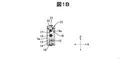
- FIG. 1A is an external perspective view of the cartridge, and FIG. 1B is a front view of the cartridge.
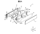
- 2A is an exploded perspective view of the cartridge, and
- FIG. 2B is a perspective view of the airbag.
- the cartridge 1 is mounted on the mounting portion 3 of the ink jet printer 2 and supplies pigment ink to the ink jet printer 2.
- the posture of the cartridge 1 shown in FIG. 1A is a mounting posture when the cartridge 1 is mounted on the mounting portion 3.
- the left-right direction in the mounting posture is defined as the width direction X of the cartridge 1.
- a mounting direction when the cartridge 1 is mounted on the mounting portion 3 in a direction orthogonal to the width direction X is a front-rear direction Y of the cartridge 1.
- the vertical direction in the mounting posture is defined as the vertical direction Z of the cartridge 1.
- the front (front side) of the cartridge 1 is the front (front side) in the mounting direction, and the rear (rear side) is the opposite direction.
- the left and right sides of the cartridge 1 are left and right when the cartridge 1 is viewed from the front.
- the cartridge 1 includes a case 5 having a rectangular parallelepiped shape.
- the case 5 has a width dimension and a height dimension that are shorter than the length dimension in the front-rear direction Y.
- the case 5 has a flat shape with a short width dimension with respect to a height dimension.
- the case 5 includes a box-shaped case main body 6 positioned on the left side and a lid body 7 positioned on the right side.
- the case body 6 and the lid body 7 are made of resin.
- the case body 6 has its opening directed to the right.
- the opening of the case body 6 is closed by a film 8 that is thermally welded to the opening edge of the case body 6.
- a film 8 that is thermally welded to the opening edge of the case body 6.
- an ink pack (liquid storage portion) 9 In a space surrounded by the case body 6 and the film 8, an ink pack (liquid storage portion) 9, a first airbag (pressing portion) 10, and a second airbag (pressing portion) 11 are stored.
- the ink pack 9 is located on the right side of the airbags 10 and 11.
- the first airbag 10 is located in front of the second airbag 11.
- the lid 7 is fixed to the case body 6 so as to cover the film 8 from the right side.
- an ink supply port (liquid supply port) 12, a first air bag air flow port (pressing part fluid flow port) 13 are provided on the front surface 5 a of the case 5 (front surface of the case body 6).
- a second air bag air circulation port (pressing part fluid circulation port) 14 and a case air circulation port (case fluid circulation port) 15 are formed.
- the first air bag air circulation port 13 and the second air bag air circulation port 14 are arranged one above the other, and the case air circulation port 15 includes the first air bag air circulation port 13 and the second air bag.
- the air circulation port 14 is provided on the right side.
- the front surface 5a of the case 5 has an ink supply port 12, a first air bag air flow port 13, a second air bag air flow port 14, and a case air flow port 15 in the vertical direction Z.
- Positioning holes (positioning portions) 17 and 18 are provided on both sides sandwiched.
- the upper positioning hole 17 is a round hole
- the lower positioning hole 18 is a long hole extending in the vertical direction Z.
- a substrate mounting portion 19 is provided at the upper end portion of the front surface 5 a of the case 5.
- the board attachment portion 19 includes a board attachment surface 19a that is inclined downward toward the front.
- a memory board 23 on which a memory 21 and a terminal 22 connected to the memory 21 are mounted is fixed to the board mounting surface 19a.
- the memory 21 stores and holds information such as the capacity of the ink filled in the ink pack 9 and the filling date when the ink pack 9 is filled with ink.
- the ink contained in the ink pack 9 is a pigment ink.
- the pigment ink the pigment is dispersed in the solvent as particles.
- the ink pack 9 includes a flexible ink storage bag 25 that stores ink, and an ink supply member 26 that supplies ink from the ink storage bag 25 to the outside.
- the ink containing bag 25 includes a first side surface portion 27 located on the left side, a second side surface portion 28 located on the right side, and a lower side connecting the lower end portion of the first side surface portion 27 and the lower end portion of the second side surface portion 28.
- a gusset portion 29 and an upper gusset portion 30 that connects the upper end portion of the first side surface portion 27 and the upper end portion of the second side surface portion 28 are provided.
- the ink containing bag 25 has a rectangular shape in which the planar shape of the upper gusset portion 30 and the lower gusset portion 29 folded inward is long in the front-rear direction Y.
- the ink containing bag 25 includes a first film 31 constituting the first side surface portion 27, a second film 32 constituting the second side surface portion 28, a third film 33 constituting the lower gusset portion 29, and an upper gusset. It is formed from the fourth film 34 constituting the part 30.
- Each of the films 31 to 34 has a bag shape in which adjacent edge portions are welded and the opening is directed forward.
- Each of the films 31 to 34 is a laminated structure including a composite barrier layer including a moisture barrier layer and a gas barrier layer, and a welding layer used for bonding.
- the composite barrier layer includes, for example, a moisture barrier layer formed from a resin film on which an inorganic oxide is deposited and a gas barrier layer made of EVOH (ethylene vinyl alcohol copolymer resin).
- the welding layer is made of PE (polyethylene) or CPP (unstretched polypropylene).
- the ink containing bag 25 communicates between the front containing bag portion 36 located on the front side, the rear containing bag portion 37 located on the rear side, and the front containing bag portion 36 and the rear containing bag portion 37.
- a communication portion 38 is provided.
- the front storage bag portion 36, the rear storage bag portion 37, and the communication portion 38 are partitioned by providing a welding portion 39 in the middle in the front-rear direction Y of the ink storage bag 25.
- the welding part 39 is formed by welding the 1st film 31 and the 2nd film 32 which oppose in the width direction only by the predetermined dimension from upper direction. Accordingly, the communication portion 38 communicates the lower end portion of the front storage bag portion 36 and the lower end portion of the rear storage bag portion 37.
- the ink supply member 26 is attached to the front end of the ink containing bag 25.
- the ink supply member 26 includes an ink supply pipe (container-side liquid supply pipe) 42 serving as an ink flow path and a pair of left and right vertical plate portions 43.
- the ink supply pipe 42 is inserted between the front edge of the first film 31 and the front edge of the second film 32 (opening of the ink containing bag 25), and is thermally welded to the first film 31 and the second film 32. ing.
- the pair of vertical plate portions 43 sandwich the front end edge of the first film 31 and the front end edge of the second film 32 from both sides in the width direction X.
- a central axis L1 of the ink supply pipe 42 extends in the front-rear direction Y (mounting direction).
- an ink supply member that does not include the pair of left and right vertical plate portions 43 but includes only the ink supply pipe 42 may be used. Also in this case, the ink supply pipe 42 is inserted between the front end edge of the first film 31 and the front end edge of the second film 32 (opening of the ink containing bag 25), and the first film 31 and the second film. 32 is heat-welded.
- the ink supply pipe 42 is connected to the ink supply port 12 on the front surface 5 a of the case 5.
- the ink pack 9 reduces its volume while the lower gusset portion 29 and the upper gusset portion 30 are folded inward when the ink amount is reduced by the ink being supplied to the outside via the ink supply pipe 42.
- the first airbag 10 and the second airbag 11 are respectively a flexible airbag main body (liquid container) 45 that can store air, introduction of air into the airbag main body 45, and the air bag main body 45 and the atmosphere.
- An air circulation pipe 46 is provided for communication.
- the length dimension of the air bags 10 and 11 in the front-rear direction Y is not more than half of the length dimension of the ink pack 9 in the front-rear direction Y.
- the height dimension of each air bag 10, 11 is the same as the height dimension of the ink pack 9.
- the first airbag 10 abuts against the front containing bag portion 36 of the ink pack 9 from the left side of the ink pack 9.
- the second airbag 11 comes into contact with the rear containing bag portion 37 of the ink pack 9 from the left side of the ink pack 9.
- the 1st airbag 10 and the 2nd airbag 11 are provided with the same structure, the 1st airbag 10 is demonstrated and description of the 2nd airbag 11 is abbreviate
- the airbag body 45 includes a first side surface portion 47 located on the left side in the width direction X, a second side surface portion 48 located on the right side, a lower end portion of the first side surface portion 47, and a second side surface portion.
- the lower gusset part 49 which connects the lower end part of the side part 48, and the upper gusset part 50 which connects the upper end part of the 1st side part 47, and the upper end part of the 2nd side part 48 are provided.
- the airbag main body 45 includes a first film 51 constituting the first side surface portion 47, a second film 52 constituting the second side surface portion 48, a third film 53 constituting the lower gusset portion 49, and It is formed from a fourth film 54 constituting the upper gusset portion 50.
- Each of the films 51 to 54 has a bag shape in which adjacent edge portions are welded and the opening is directed forward.
- the films 51 to 54 have the same structure as the films 31 to 34 constituting the ink containing bag 25 of the ink pack 9.
- the air circulation pipe 46 is attached to the front end portion of the airbag main body 45. More specifically, it is inserted between the first film 51 and the second film 52 and thermally welded to the first film 51 and the second film 52. A central axis L2 of the air flow pipe 46 extends in the front-rear direction Y (mounting direction).
- the air circulation pipe 46 of the first airbag 10 is connected to the first airbag air circulation port 13 on the front surface 5a of the case 5 via the first connecting pipe 55.
- the air circulation pipe 46 of the second airbag 11 is connected to the second airbag air circulation port 14 on the front surface 5 a of the case 5 via the second connecting pipe 56.
- FIG. 3 is an explanatory diagram of a state where the cartridge is mounted on the mounting portion 3 of the inkjet printer 2.
- the mounting portion 3 of the ink jet printer 2 has an ink introduction port 61 protruding from the facing surface 3a, a mounting portion side first air circulation port 62, and a mounting portion side second air circulation on the facing surface 3a facing the front surface 5a of the cartridge 1.
- a port 63 and a mounting portion side third air circulation port 64 are provided.
- the mounting portion 3 includes a pair of positioning pins 65 and 66 and a contact mechanism 67 on the facing surface 3a.
- the ink inlet 61 is an upstream end of an ink supply path 69 for supplying ink to the inkjet head 68.
- the mounting portion side first air circulation port 62 is a downstream end of the first air flow passage 71 of the air supply mechanism 70 mounted on the inkjet printer 2.
- the mounting portion side second air circulation port 63 is a downstream end of the second air flow passage 72 of the air supply mechanism 70.
- the mounting portion side third air circulation port 64 is a downstream end of the third air flow passage 73 of the air supply mechanism 70.
- the pair of positioning pins 65 and 66 are, in the vertical direction Z, the ink introduction port 61, the mounting portion side first air circulation port 62, the mounting portion side second air circulation port 63, and the mounting portion side third air circulation port 64. It is provided on both sides with a gap in between.
- the positioning pins 65 and 66 project from the facing surface 3a in the cartridge mounting direction (front-rear direction Y).
- the air supply mechanism 70 includes a pressurizing pump 74, a first air flow passage 71, a second air flow passage 72, a third air flow passage 73, and a select valve 75.
- the pressure pump 74 is connected to the upstream ends of the first air flow passage 71, the second air flow passage 72 and the third air flow passage 73.
- the first air flow passage 71, the second air flow passage 72, and the third air flow passage 73 are connected to the pressurizing pump 74 by integrating the flow passage portions upstream of the select valve 75.
- the pressurization pump 74 and the select valve 75 are driven and controlled by the control unit 78 of the inkjet printer 2 that controls the printing operation.
- the select valve 75 includes a first air flow path selection position 75A for selecting the first air flow path 71, a second air flow path selection position 75B for selecting the second air flow path 72, and a third air.
- the flow path 73 is moved between the third air flow path selection positions 75C for selecting.
- the select valve 75 In the state where the select valve 75 is arranged at the first air flow path selection position 75A, the pressurizing pump 74 and the mounting portion side first air circulation port 62 communicate with each other. On the other hand, the mounting portion side second air circulation port 63 and the mounting portion side third air circulation port 64 communicate with the atmosphere via the select valve 75. In a state where the select valve 75 has the valve disposed at the second air flow path selection position 75B, the pressurizing pump 74 and the mounting portion side second air circulation port 63 communicate with each other. On the other hand, the mounting portion side first air circulation port 62 and the mounting portion side third air circulation port 64 communicate with the atmosphere via the select valve 75.
- the pressurizing pump 74 and the mounting portion side third air circulation port 64 communicate with each other.
- the mounting portion side first air circulation port 62 and the mounting portion side second air circulation port 63 communicate with the atmosphere via the select valve 75.
- the cartridge 1 When the cartridge 1 is mounted on the mounting portion 3, first, the tips of the pair of positioning pins 65 and 66 are inserted into the positioning holes 17 and 18 of the cartridge 1. Thereby, the cartridge 1 is in a state where the positions in the vertical direction Z and the width direction X are restricted. Thereafter, when the cartridge 1 is pushed forward, the ink supply port 12 of the cartridge 1 is connected to the ink introduction port 61. In parallel with this, the first air bag air circulation port 13 of the cartridge 1 is connected to the mounting portion side first air circulation port 62, and the second air bag air circulation port 14 is connected to the mounting portion side second air circulation port. 63 and the case air circulation port 15 is connected to the mounting portion side third air circulation port 64.
- the contact mechanism 67 is electrically connected to the terminal 22 of the memory substrate 23. Accordingly, the control unit 78 can read information from the memory 21 and write information to the memory 21.
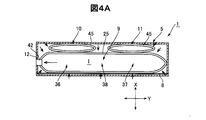
- FIGS. 3 and 4A to 4C are explanatory diagrams of the ink supply operation and the ink agitation operation in the cartridge 1.
- FIG. 4 shows a cross section of the cartridge 1 cut along a plane perpendicular to the vertical direction Z.
- 4A shows a state where pressurized air is introduced into the case 5
- FIG. 4B shows a state where pressurized air is introduced into the first airbag 10
- FIG. 4C shows a second airbag.
- 11 is a state in which pressurized air is introduced.
- the controller 78 drives the select valve 75 to move the valve to the third air flow path selection position 75C. That is, the control unit 78 drives the select valve 75 to cause the pressurizing pump 74 and the mounting unit side third air circulation port 64 to communicate with each other. Then, the control unit 78 drives the pressurizing pump 74. Thereby, the pressurized air is introduced from the third air flow passage 73 into the case 5 through the mounting portion side third air circulation port 64 and the case air circulation port 15.
- the mounting portion side first air circulation port 62 and the mounting portion side second air circulation port 63 are connected to the atmosphere via the selection valve 75. Communicate with. Accordingly, the first airbag 10 and the second airbag 11 are opened to the atmosphere.
- the ink pack 9 is pressurized from the outside as shown by the arrow in FIG. 4A. Therefore, the ink I in the ink containing bag 25 is supplied from the ink supply port 12 to the inkjet head 68 via the ink introduction port 61 and the ink supply path 69 of the mounting portion 3.
- control unit 78 stops the pressurizing pump 74. In addition, the control unit 78 performs an ink stirring operation.
- the controller 78 first drives the select valve 75 to move the valve from the third air flow path selection position 75C to the first air flow path selection position 75A. That is, the control unit 78 drives the select valve 75 to connect the pressurizing pump 74 and the mounting unit side first air circulation port 62. Then, the control unit 78 drives the pressurizing pump 74. Thus, the pressurized air is introduced from the first air flow passage 71 into the first airbag 10 through the mounting portion side first air circulation port 62 and the first air bag air circulation port 13. .
- the mounting portion side second air circulation port 63 and the mounting portion side third air circulation port 64 communicate with the atmosphere via the selection valve 75. To do. Accordingly, the second airbag 11 and the case 5 are opened to the atmosphere. Thereby, since the internal pressure of the 2nd airbag 11 and the internal pressure of case 5 fall, the 2nd airbag 11 and the ink pack 9 will be in the state which is easy to deform
- the airbag body 45 of the first airbag 10 expands as shown in FIG. 4B, and the front storage bag portion 36 of the ink pack 9 is moved to the right. Crush in the direction. Thereby, the ink in the front side accommodation bag part 36 moves. Accordingly, the ink I in the front containing bag portion 36 is agitated.
- the front storage bag portion 36 is crushed, the ink I moves from the front storage bag portion 36 to the rear storage bag portion 37 via the communication portion 38. As a result, convection of the ink I occurs in the rear containing bag portion 37. Accordingly, the ink I in the rear containing bag portion 37 is also stirred.
- the controller 78 drives the select valve 75 to move the valve from the first air flow path selection position 75A to the second air flow path selection position 75B. That is, the control unit 78 drives the select valve 75 to connect the select valve 75 and the mounting portion side second air circulation port 63. Then, the control unit 78 drives the pressurizing pump 74. Thus, the pressurized air is introduced from the second air flow passage 72 into the second airbag 11 through the mounting portion side second air circulation port 63 and the second air bag air circulation port 14. .
- the mounting portion side first air circulation port 62 and the mounting portion side third air circulation port 64 communicate with the atmosphere via the selection valve 75. To do. Accordingly, the first airbag 10 and the case 5 are opened to the atmosphere. Thereby, since the internal pressure of the 1st airbag 10 and the internal pressure of case 5 fall, the 1st airbag 10 and the ink pack 9 will be in the state which is easy to deform
- ink I is a pigment ink. Therefore, the pigment dispersed in the solvent may settle and settle on the lower part of the ink pack 9. The precipitation of the pigment causes the density unevenness of the ink I in the ink pack 9.
- unevenness in density may occur in the printing, and print quality may deteriorate.
- the air bag main body 45 of the first air bag 10 and the air bag main body 45 of the second air bag 11 are alternately expanded and contracted by the ink stirring operation, and the ink pack 9 is moved in the front-rear direction Y. Scale alternately.
- the ink pack 9 is deformed and the ink I moves in the ink pack 9, so that the settled pigment is agitated. Therefore, the density unevenness of the ink I (pigment ink) in the ink pack 9 can be eliminated.
- air is supplied to the first airbag 10 and the second airbag 11 and air is introduced into the case 5 by using a single pressurizing pump 74 and a select valve 75. Therefore, the structure of the inkjet printer 2 can be simplified and the manufacturing cost can be suppressed.
- the ink stirring operation can be performed, for example, when the power to the ink jet printer 2 is turned on. Further, based on information such as the ink filling date stored in the memory 21 of the memory substrate 23, the timing and frequency of performing the ink stirring operation may be set.
- FIG. 5A is an explanatory view of a cartridge according to Modification 1 including a bulge width defining member that defines the maximum bulge width of the first airbag 10, and FIG. 5B is a bulge width defining mechanism that regulates the bulge width of the first airbag 10. It is explanatory drawing of the cartridge of the modification 2 provided with this.
- 5A shows a cross section of the cartridge 1 cut along a plane perpendicular to the up-down direction Z
- FIG. 5B shows a cross section of the cartridge 1 cut along a plane orthogonal to the front-rear direction Y.
- the first airbag 10 includes a bulge width defining member that defines the maximum bulge width of the airbag body 45.
- the bulge width defining member is a rectangular plate member 81 and is disposed inside the airbag body 45 with its thickness direction directed in the width direction X.
- the plate member 81 interferes with the airbag body 45 when the airbag body 45 is inflated, and restricts the expansion in the width direction X.
- the first air bag 10 can adjust the amount by which the ink pack 9 pushes the ink pack 9 in the width direction X, it is possible to prevent the ink containing bag 25 from being displaced excessively with respect to the ink supply pipe 42. Thereby, even when the ink stirring operation is repeated, it is possible to prevent the welded portion between the ink containing bag 25 and the ink supply pipe 42 from being damaged. Therefore, ink does not leak from the ink pack 9 due to the ink stirring operation.
- the second airbag 11 may be provided with a bulge width defining member similar to that of the first airbag 10.
- the width dimension D of the airbag main body 45 when the volume is maximized by the introduction of air by the bulge width regulating member is changed from the inner surface (inner wall surface portion) 5 b of the left side plate of the case 5 to the ink of the ink pack 9. If the distance is equal to or less than the distance to the axis L1 of the supply pipe 42, the ink containing bag 25 can be reliably prevented from being displaced excessively with respect to the ink supply pipe 42.
- the first airbag 10 includes a bulge width defining mechanism 82 that regulates the maximum bulge width of the airbag body 45.
- the bulge width regulating mechanism 82 projects inward from the plate member 83 attached to the second side surface portion 48 (side surface portion on the ink pack 9 side) of the first airbag 10 and the upper and lower plate portions of the case 5.
- a pair of protrusions 84 are provided.
- the pair of protrusions 84 abut against the plate member 83 from the ink pack 9 side at a predetermined position in the width direction X, and the plate member 83 is Further, the ink pack 9 is prevented from moving to the ink pack 9 side.
- the first air bag 10 can adjust the amount by which the ink pack 9 pushes the ink pack 9 in the width direction X, it is possible to prevent the ink containing bag 25 from being displaced excessively with respect to the ink supply pipe 42. Accordingly, even when the ink agitation operation is repeated, the welded portion between the ink containing bag 25 and the ink supply pipe 42 can be prevented from being damaged, so that ink leaks from the ink pack 9 due to the ink agitation operation. There is no.
- the second airbag 11 may be provided with a bulge width defining mechanism 82 similar to that of the first airbag 10.
- the width of the airbag body 45 is changed from the inner surface (inner wall surface portion) 5 b of the left side plate of the case 5 to the ink of the ink pack 9. If the distance is equal to or less than the distance to the axis L1 of the supply pipe 42, the ink containing bag 25 can be reliably prevented from being displaced excessively with respect to the ink supply pipe 42.
- the width D of the airbag body 45 when the volume is maximized by the introduction of air is the ink supply of the ink pack 9 from the inner surface (inner wall surface portion) 5 b of the left side plate of the case 5.
- the ink containing bag 25 can be prevented from being excessively displaced with respect to the ink supply tube 42.
- the ink I is not limited to the pigment ink, and includes, for example, an ink in which particles are present in the ink, such as a disperse dye ink.
- the cartridges 1, 1A, and 1B include two airbags, but the number of airbags may be one or three or more.
- the ink pack 9 when the ink pack 9 is inclined downward in the mounting posture in the front-rear direction Y (mounting direction), the ink can be sufficiently stirred even if only the first airbag 10 is used. That is, when the ink pack 9 is inclined downward toward the front, the pigment is deposited on the front portion (lower portion) of the ink containing bag 25 in the mounting posture. Therefore, if the front portion of the ink containing bag 25 is pressed and deformed by the first airbag 10, the portion in the ink pack 9 where the pigment tends to accumulate can be agitated, and the uneven density of the ink can be easily eliminated.
- the ink containing bag 25 is provided with the front containing bag portion 36, the rear containing bag portion 37, and the communication portion 38 by providing the welding portion 39, but the inner surface of the left side plate of the case main body 6. 5b is provided with a rib protruding rightward, and the center in the front-rear direction Y of the ink containing bag 25 is partially crushed from the upper side by this rib, so that the ink containing bag 25 becomes the front containing bag portion 36, the rear containing bag.
- the portion 37 and the communication portion 38 may be provided.
- the ink containing bag 25 of the ink pack 9 is entirely made of a flexible film, but a part of the bag may be made of a rigid body.
- the airbag main body 45 of the airbags 10 and 11 is entirely made of a flexible film, but may have a bag portion made of a rigid body in a part thereof.
- the present invention is applied to the cartridge 1 containing the ink I to be supplied to the ink jet printer 2.
- a liquid crystal display, an EL display, an FED (surface emitting display), etc. are manufactured.
- the present invention may be applied to cartridges that contain various liquids, such as electrode materials and color materials (liquids in which electrode materials and color materials are dissolved in a solvent).
- the cartridge includes a repeater (so-called adapter) that, after being mounted on the liquid ejecting apparatus, receives liquid replenishment from the outside and supplies the liquid to the liquid ejecting apparatus.
- Terminal 23 ... Memory board, 25..Ink storage bag (liquid container), 26 ..Ink supply member 27..First side portion 28..Second side portion 29..Lower gusset portion 30..Upper gusset portion 31-34..Film 36..Front storage bag portion 37 .. Rear side containing bag part, 38 .. Communication part, 39 .. Welding part, 42 .. Ink supply pipe (container side liquid supply pipe), 43 .. Vertical plate part, 45. Container), 46 .. air circulation pipe, 47 .. first side part, 48 .. second side part, 49 .. lower gusset part, 50 .. upper gusset part, 51 to 54 ..
Abstract
Provided is a cartridge that is easy to mount and that makes it possible to stir a fluid accommodated therein. The cartridge 1 is mounted to an inkjet printer 2 and supplies pigment ink. The cartridge 1 is provided with an ink pack 9, a first air bag 10, and a case 5 for accommodating these components. The case 5 is provided with an ink supply port 12, an air flow port 13 for the first air bag, and an air flow port 15 for the case on the front surface 5a in the mounting direction. When pressurized air is introduced into the first air bag 10 via the air flow port 13 for the first air bag, the first air bag 10 expands and presses the ink pack 9, thereby making it possible to stir the ink I therein. It is easy to mount the cartridge 1 to the inkjet printer 2 because the ink supply port 12, the air flow port 13 for the first air bag, and the air flow port 15 for the case are on the front surface of the cartridge 1.
Description
本発明は、プリンターなどの液体噴射装置に装着されて、顔料インクなどの液体を供給するカートリッジに関する。
The present invention relates to a cartridge that is mounted on a liquid ejecting apparatus such as a printer and supplies a liquid such as pigment ink.
顔料インクは顔料が粒子として溶媒中に分散している。従って、インクパック(液体収容部)に収容された顔料インクには、顔料の沈降に起因して、上側の顔料濃度が薄く下側の顔料濃度が濃くなるという濃度むらが発生することがある。濃度むらのある顔料インクがインクジェットプリンターに供給されて印刷に用いられると、印刷に濃淡のむらが発生して、印刷品質が低下する可能性がある。
In pigment ink, pigment is dispersed in a solvent as particles. Therefore, in the pigment ink stored in the ink pack (liquid storage unit), density unevenness in which the upper pigment density is thin and the lower pigment density is high may occur due to the sedimentation of the pigment. When pigment ink with uneven density is supplied to an ink jet printer and used for printing, shading unevenness may occur in printing and print quality may deteriorate.
このような印刷品質の低下を回避するために、インクパックに収容された顔料インクを攪拌するための機構を備えたカートリッジが提案されている。特許文献1のカートリッジは、インクを収容する可撓性の液体容器を備えるインクパックと、形状復元性を有する可撓性のエアーバッグと、インクパックおよびエアーバッグを収容するケースを有する。ケースは装着方向が長く、装着方向と直交する幅方向が短い偏平な直方体形状をしている。エアーバッグは幅方向でインクパックと隣り合う位置に配置されている。装着方向におけるケースの前面には、顔料インクをインクパックから外部に供給するためのインク供給口が設けられている。また、ケースの前面には、ケースへの空気の導入とケースと大気との連通を行うエアー流通口が設けられている。ケースの側面には、エアーバッグを大気と連通させるための大気連通口が設けられている。
In order to avoid such a decrease in print quality, a cartridge having a mechanism for stirring the pigment ink contained in the ink pack has been proposed. The cartridge of Patent Document 1 includes an ink pack including a flexible liquid container that stores ink, a flexible air bag having shape restoring properties, and a case that stores the ink pack and the air bag. The case has a flat rectangular parallelepiped shape with a long mounting direction and a short width direction perpendicular to the mounting direction. The airbag is arranged at a position adjacent to the ink pack in the width direction. An ink supply port for supplying pigment ink from the ink pack to the outside is provided on the front surface of the case in the mounting direction. Further, an air circulation port for introducing air into the case and communicating the case with the atmosphere is provided on the front surface of the case. An air communication port for communicating the air bag with the atmosphere is provided on the side surface of the case.
印刷時などにプリンターに顔料インクを供給する際には、エアー流通口を介してケースに加圧された空気が導入される。これにより、インクパックは外側から加圧されるので、インクパック内の顔料インクはインク供給口を介してプリンターの側に供給される。また、ケース内に加圧された空気が導入されると、その圧力により、エアーバッグは収縮する。その後、プリンターへの顔料インクの供給が終了すると、ケース内はエアー流通口を介して大気に開放される。ケースが大気に開放されると、ケース内の圧力が低下する。従って、エアーバッグはその形状復元性により拡張して元の形状に戻る。ここで、エアーバッグが元の形状に戻る際にエアーバッグはインクパックを押圧してインクパックを変形させる。これによりインクパック内の顔料インクは攪拌され、その濃度むらが是正される。
When supplying pigment ink to the printer during printing or the like, pressurized air is introduced into the case through the air circulation port. Thus, the ink pack is pressurized from the outside, and the pigment ink in the ink pack is supplied to the printer side through the ink supply port. Further, when pressurized air is introduced into the case, the air bag contracts due to the pressure. Thereafter, when the supply of the pigment ink to the printer is completed, the inside of the case is opened to the atmosphere via the air circulation port. When the case is opened to the atmosphere, the pressure in the case decreases. Therefore, the airbag expands due to its shape restoring property and returns to its original shape. Here, when the airbag returns to its original shape, the airbag presses the ink pack and deforms the ink pack. As a result, the pigment ink in the ink pack is agitated, and the density unevenness is corrected.
ここで、特許文献1のエアーバッグに加圧した空気を流入させれば、この空気によってエアーバッグを能動的に拡張できる。従って、エアーバッグによってインクパックを積極的に押圧して、インクパック内の顔料インクを攪拌することが可能となる。しかし、エアーバッグに加圧した空気を流入させるためには、カートリッジをインクジェットプリンターに装着したときに、インクジェットプリンターの側に搭載された圧縮空気供給機構とエアーバッグとを接続する必要がある。
Here, if pressurized air is introduced into the air bag of Patent Document 1, the air bag can be actively expanded by this air. Therefore, the ink pack can be positively pressed by the air bag, and the pigment ink in the ink pack can be stirred. However, in order to allow the pressurized air to flow into the air bag, it is necessary to connect the compressed air supply mechanism mounted on the ink jet printer side and the air bag when the cartridge is mounted on the ink jet printer.
本発明の課題は、このような点に鑑みて、液体噴射装置への装着が容易で、内部に収容した液体を攪拌できるカートリッジを提供することにある。
In view of these points, an object of the present invention is to provide a cartridge that can be easily attached to a liquid ejecting apparatus and can stir the liquid contained therein.
上記の課題を解決するために、本発明のカートリッジは、液体噴射装置に装着されて液体を供給するカートリッジにおいて、前記液体を収容する少なくとも一部が可撓性の液体容器を備える液体収容部と、前記液体容器に当接可能な少なくとも一部が可撓性の容器を備える押圧部と、前記液体収容部および前記押圧部を収容するケースと、を有し、装着方向における前記ケースの前面には、前記液体収容部から外部に液体を供給するための液体供給口と、前記容器への流体の導入および当該容器と大気との連通を行うための押圧部用流体流通口と、前記ケースへの流体の導入および当該ケースと大気との連通を行うケース用流体流通口と、が設けられていることを特徴とする。
In order to solve the above-described problems, a cartridge according to the present invention is a cartridge that is mounted on a liquid ejecting apparatus and supplies a liquid. At least a part of the cartridge that contains the liquid includes a flexible liquid container; A pressing portion provided with a flexible container at least partially capable of contacting the liquid container, and a case for storing the liquid storage portion and the pressing portion, on the front surface of the case in the mounting direction. A liquid supply port for supplying liquid from the liquid storage unit to the outside, a fluid flow port for a pressing unit for introducing fluid into the container and communicating the container with the atmosphere, and the case And a case fluid circulation port for introducing the fluid and communicating the case with the atmosphere.
本発明では、液体噴射装置に液体を供給する際には、ケース用流体流通口を介してケース内に流体を導入する。これにより、可撓性の液体収容部は外側から加圧される。従って、液体収容部内の液体は液体供給口を介して液体噴射装置の側に供給される。そして、液体噴射装置への液体の供給が終了すると、流体流通口を介してケース内を大気開放する。また、液体収容部に収容された液体の攪拌が必要な場合には、押圧部用流体流通口を介して容器内に流体を導入する。これにより、押圧部の容器は拡張して液体容器を押圧する。これにより、液体容器が変形するので、液体容器内の液体が攪拌される。ここで、押圧部用流体流通口は、液体供給口およびケース用流体流通口と共にケースの前面に設けられる。従って、カートリッジを液体噴射装置に装着する際に、液体供給口を液体噴射装置の側に設けられた液体導入口と接続することが容易であり、かつ、押圧部用流体流通口およびケース用流体流通口を液体噴射装置の側に設けられた流体供給機構と接続することが容易である。
In the present invention, when supplying the liquid to the liquid ejecting apparatus, the fluid is introduced into the case via the case fluid circulation port. Thereby, the flexible liquid container is pressurized from the outside. Therefore, the liquid in the liquid container is supplied to the liquid ejecting apparatus side through the liquid supply port. When the supply of the liquid to the liquid ejecting apparatus is completed, the inside of the case is opened to the atmosphere via the fluid circulation port. In addition, when stirring of the liquid stored in the liquid storage unit is necessary, the fluid is introduced into the container through the fluid flow port for the pressing unit. Thereby, the container of a press part expands and presses a liquid container. Thereby, since the liquid container is deformed, the liquid in the liquid container is stirred. Here, the fluid circulation port for the pressing part is provided on the front surface of the case together with the liquid supply port and the fluid circulation port for the case. Therefore, when the cartridge is mounted on the liquid ejecting apparatus, it is easy to connect the liquid supply port to the liquid introducing port provided on the liquid ejecting apparatus side, and the pressing portion fluid circulation port and the case fluid It is easy to connect the flow port to a fluid supply mechanism provided on the liquid ejecting apparatus side.
本発明において、前記前面には、前記液体供給口、前記押圧部用流体流通口および前記ケース用流体流通口を間に挟んだ両側に、装着時に前記ケースを位置決めするための位置決め部が設けられているが望ましい。このようにすれば、液体供給口を液体噴射装置の側の液体導入口と接続することがさらに容易となる。また、押圧部用流体流通口およびケース用流体流通口を液体噴射装置の側の流体供給機構と接続することがさらに容易となる。
In the present invention, the front surface is provided with positioning portions for positioning the case at the time of mounting on both sides of the liquid supply port, the pressing portion fluid circulation port and the case fluid circulation port. It is desirable. This makes it easier to connect the liquid supply port to the liquid inlet on the liquid ejecting apparatus side. Further, it becomes easier to connect the fluid circulation port for the pressing portion and the fluid circulation port for the case with the fluid supply mechanism on the liquid ejecting apparatus side.
本発明において、前記押圧部として、複数の押圧部を備え、前記前面には、各押圧部の前記押圧部用流体流通口が設けられているものとすることができる。このようにすれば、各押圧部に独立したタイミングで流体を導入することができるので、各押圧部が液体容器を異なるタイミングで押圧できる。従って、押圧部により液体容器内の液体をよく攪拌できる。
In the present invention, the pressing portion may include a plurality of pressing portions, and the pressing portion fluid circulation port of each pressing portion may be provided on the front surface. If it does in this way, since a fluid can be introduced into each press part at an independent timing, each press part can press a liquid container at a different timing. Therefore, the liquid in the liquid container can be well stirred by the pressing portion.
本発明において、前記液体容器は、前記装着方向の前側に位置する前側液体容器部分と、後側に位置する後側液体容器部分と、前記前側液体容器部分と前記後側液体容器部分との間を連通させる連通部分とを備えており、前記連通部分は、装着姿勢における前記前側液体容器部分の下端部と前記後側液体容器部分の下端部とを連通させるものとすることができる。このような構成では、押圧部によって前側液体容器部分を押圧した場合には、前側液体容器部分内をインクが移動する。従って、前側液体容器部分の液体が攪拌される。また、押圧部によって前側液体容器部分を押圧した場合には、連通部分を介して液体が前側液体容器部分から後側液体容器部分に移動して、後側液体容器部分に対流を発生させる。従って、後側液体容器部分の液体もよく攪拌される。また、押圧部によって後側液体容器部分を押圧した場合には、後側液体容器部分内をインクが移動する。従って、後側液体容器部分の液体が攪拌される。また、押圧部によって後側液体容器部分を押圧した場合には、連通部分を介して液体が後側液体容器部分から前側液体容器部分に移動して、前側液体容器部分に対流を発生させる。従って、前側液体容器部分の液体もよく攪拌される。
In the present invention, the liquid container includes a front liquid container part located on the front side in the mounting direction, a rear liquid container part located on the rear side, and a space between the front liquid container part and the rear liquid container part. A communication portion that allows communication between the lower end portion of the front liquid container portion and the lower end portion of the rear liquid container portion in the mounting posture. In such a configuration, when the front liquid container portion is pressed by the pressing portion, the ink moves in the front liquid container portion. Accordingly, the liquid in the front liquid container portion is agitated. Further, when the front liquid container part is pressed by the pressing part, the liquid moves from the front liquid container part to the rear liquid container part via the communication part, and convection is generated in the rear liquid container part. Accordingly, the liquid in the rear liquid container portion is also well stirred. Further, when the rear liquid container portion is pressed by the pressing portion, the ink moves in the rear liquid container portion. Accordingly, the liquid in the rear liquid container portion is agitated. Further, when the rear liquid container part is pressed by the pressing part, the liquid moves from the rear liquid container part to the front liquid container part via the communication part, and convection is generated in the front liquid container part. Therefore, the liquid in the front liquid container portion is also well stirred.
本発明において、前記液体容器は、装着姿勢において、前記装着方向の前方に向かって下方に傾斜しており、前記容器は、前記装着方向における前記液体容器の前側部分に当接可能であることが望ましい。液体が沈降成分を有する場合には、この沈降成分は、装着姿勢における液体収容部の下側部分に沈殿する。これに対して、斜めに配置した液体容器の前側部分(下側部分)を押圧部により押圧すれば、沈降成分が溜まりやすい部分を攪拌できるので、液体の濃度むらを解消しやすい。
In the present invention, in the mounting posture, the liquid container is inclined downward toward the front in the mounting direction, and the container can be in contact with a front portion of the liquid container in the mounting direction. desirable. In the case where the liquid has a sediment component, the sediment component is deposited on the lower portion of the liquid storage portion in the mounting posture. On the other hand, if the front side portion (lower side portion) of the liquid container disposed obliquely is pressed by the pressing portion, the portion where the sedimentation component tends to accumulate can be stirred, and thus the liquid concentration unevenness can be easily eliminated.
本発明において、前記液体収容部は、前記装着方向の前端部分に前記液体容器から外部に液体を供給するための容器側液体供給管を備え、前記容器側液体供給管は、その軸線を前記装着方向に向けて前記液体供給口に接続され、前記容器は、前記ケースにおいて前記装着方向と直交する直交方向を向く内壁面部分と前記液体容器との間に配置され、流体の導入によって容積が最大となった場合の前記容器の前記直交方向における幅寸法は、前記内壁面部分と前記軸線との間の距離以下であることが望ましい。このようにすれば、押圧部が拡張して液体容器を変形させたときに、液体供給管に対する液体容器の過度な変位を抑制できる。従って、液体容器と液体供給管の間から液体が漏れることを防止できる。
In the present invention, the liquid storage portion includes a container-side liquid supply pipe for supplying liquid from the liquid container to the outside at a front end portion in the mounting direction, and the container-side liquid supply pipe has its axis line attached to the liquid container. Connected to the liquid supply port in a direction, and the container is disposed between the liquid container and the inner wall surface portion facing the orthogonal direction orthogonal to the mounting direction in the case, and the volume is maximized by introduction of fluid. In this case, the width dimension in the orthogonal direction of the container is preferably equal to or less than the distance between the inner wall surface portion and the axis. If it does in this way, when a press part expands and deforms a liquid container, the excessive displacement of a liquid container to a liquid supply pipe can be controlled. Therefore, it is possible to prevent liquid from leaking between the liquid container and the liquid supply pipe.
本発明において、前記押圧部は、前記容器内に配置され、前記容器が膨らんだときに当該容器と干渉して、その膨らみの最大幅を規定する膨らみ幅規定部材を備えることが望ましい。このようにすれば、押圧部の過度な拡張を防止できるので、押圧部が液体容器を変形させたときに、液体供給管に対する液体容器の過度な変位を抑制できる。従って、液体容器と液体供給管の間から液体が漏れることを防止できる。
In the present invention, it is desirable that the pressing portion includes a bulge width defining member that is disposed in the container and interferes with the container when the container swells to define the maximum width of the bulge. If it does in this way, since the expansion of a press part can be prevented, when a press part deform | transforms a liquid container, the excessive displacement of the liquid container with respect to a liquid supply pipe | tube can be suppressed. Therefore, it is possible to prevent liquid from leaking between the liquid container and the liquid supply pipe.
本発明において、前記容器の膨らみ幅を規制する膨らみ幅規定機構を有し、前記液体収容部は、前記装着方向の前端部分に前記液体容器から外部に液体を供給するための容器側液体供給管を備え、前記容器側液体供給管は、その軸線を前記装着方向に向けて前記液体供給口に接続され、前記容器は、前記装着方向と直交する直交方向で前記液体容器と隣り合う位置に配置され、前記膨らみ幅規定機構は、前記容器における前記液体容器と対向する部分に取り付けられた板部材と、前記ケースから内側に突出して前記液体容器の側から前記板部材に当接可能な突部と、を有するものとすることができる。このようにすれば、押圧部が液体収容部の側に過度に拡張することを防止できるので、押圧部が液体容器を変形させたときに、液体供給管に対する液体容器の過度な変位を抑制できる。従って、液体容器と液体供給管の間から液体が漏れることを防止できる。
In the present invention, a container-side liquid supply pipe having a bulge width defining mechanism for regulating a bulge width of the container, wherein the liquid storage portion supplies liquid from the liquid container to the front end portion in the mounting direction. The container-side liquid supply pipe is connected to the liquid supply port with its axis line oriented in the mounting direction, and the container is disposed at a position adjacent to the liquid container in a direction orthogonal to the mounting direction. The bulge width defining mechanism includes a plate member attached to a portion of the container that faces the liquid container, and a protrusion that protrudes inward from the case and can contact the plate member from the liquid container side. And can have. If it does in this way, since it can prevent that a press part expands too much to the liquid storage part side, when a press part deform | transforms a liquid container, the excessive displacement of the liquid container with respect to a liquid supply pipe | tube can be suppressed. . Therefore, it is possible to prevent liquid from leaking between the liquid container and the liquid supply pipe.
以下に、図面を参照して、本発明の実施の形態であるカートリッジを説明する。
Hereinafter, a cartridge according to an embodiment of the present invention will be described with reference to the drawings.
(カートリッジの全体構成)
図1Aはカートリッジの外観斜視図であり、図1Bはカートリッジの正面図である。図2Aはカートリッジの分解斜視図であり、図2Bはエアーバッグの斜視図である。 (Entire cartridge configuration)
FIG. 1A is an external perspective view of the cartridge, and FIG. 1B is a front view of the cartridge. 2A is an exploded perspective view of the cartridge, and FIG. 2B is a perspective view of the airbag.
カートリッジ1は、インクジェットプリンター2の装着部3に装着されて顔料インクをインクジェットプリンター2に供給する。図1Aに示すカートリッジ1の姿勢は、カートリッジ1が装着部3に装着される際の装着姿勢である。以下の説明では、装着姿勢における左右方向をカートリッジ1の幅方向Xとする。幅方向Xと直交する方向であってカートリッジ1を装着部3に装着する際の装着方向をカートリッジ1の前後方向Yとする。また、装着姿勢における上下方向をカートリッジ1の上下方向Zとする。カートリッジ1の前方(前側)は、装着方向における前方(前側)であり、後方(後側)は、その反対方向である。カートリッジ1の左右は、カートリッジ1を前方から見た場合の左右である。
The cartridge 1 is mounted on the mounting portion 3 of the ink jet printer 2 and supplies pigment ink to the ink jet printer 2. The posture of the cartridge 1 shown in FIG. 1A is a mounting posture when the cartridge 1 is mounted on the mounting portion 3. In the following description, the left-right direction in the mounting posture is defined as the width direction X of the cartridge 1. A mounting direction when the cartridge 1 is mounted on the mounting portion 3 in a direction orthogonal to the width direction X is a front-rear direction Y of the cartridge 1. Further, the vertical direction in the mounting posture is defined as the vertical direction Z of the cartridge 1. The front (front side) of the cartridge 1 is the front (front side) in the mounting direction, and the rear (rear side) is the opposite direction. The left and right sides of the cartridge 1 are left and right when the cartridge 1 is viewed from the front.
図1Aに示すように、カートリッジ1は、直方体形状のケース5を備える。ケース5は、前後方向Yの長さ寸法に対して幅寸法および高さ寸法が短い。また、ケース5は、高さ寸法に対して幅寸法が短い扁平形状である。ケース5は左側に位置する箱型のケース本体6と、右側に位置する蓋体7を備える。ケース本体6および蓋体7は樹脂製である。
As shown in FIG. 1A, the cartridge 1 includes a case 5 having a rectangular parallelepiped shape. The case 5 has a width dimension and a height dimension that are shorter than the length dimension in the front-rear direction Y. The case 5 has a flat shape with a short width dimension with respect to a height dimension. The case 5 includes a box-shaped case main body 6 positioned on the left side and a lid body 7 positioned on the right side. The case body 6 and the lid body 7 are made of resin.
図2Aに示すように、ケース本体6は、その開口を右側に向けている。ケース本体6の開口は、ケース本体6の開口縁に熱溶着されたフィルム8により塞がれている。ケース本体6とフィルム8によって囲まれた空間には、インクパック(液体収容部)9、第1エアーバッグ(押圧部)10および第2エアーバッグ(押圧部)11が収容されている。インクパック9はエアーバッグ10、11の右側に位置する。第1エアーバッグ10は第2エアーバッグ11の前方に位置する。蓋体7は、フィルム8を右側から被うようにしてケース本体6に固定されている。
As shown in FIG. 2A, the case body 6 has its opening directed to the right. The opening of the case body 6 is closed by a film 8 that is thermally welded to the opening edge of the case body 6. In a space surrounded by the case body 6 and the film 8, an ink pack (liquid storage portion) 9, a first airbag (pressing portion) 10, and a second airbag (pressing portion) 11 are stored. The ink pack 9 is located on the right side of the airbags 10 and 11. The first airbag 10 is located in front of the second airbag 11. The lid 7 is fixed to the case body 6 so as to cover the film 8 from the right side.
図1Bに示すように、ケース5の前面5a(ケース本体6の前面)には、インク供給口(液体供給口)12、第1エアーバッグ用空気流通口(押圧部用流体流通口)13、第2エアーバッグ用空気流通口(押圧部用流体流通口)14、ケース用空気流通口(ケース用流体流通口)15が形成されている。第1エアーバッグ用空気流通口13と第2エアーバッグ用空気流通口14は上下に配列されており、ケース用空気流通口15は、これら第1エアーバッグ用空気流通口13および第2エアーバッグ用空気流通口14の右側に設けられている。また、ケース5の前面5aには、インク供給口12、第1エアーバッグ用空気流通口13、第2エアーバッグ用空気流通口14、および、ケース用空気流通口15を上下方向Zで間に挟んだ両側に位置決め穴(位置決め部)17、18が設けられている。上側の位置決め穴17は丸穴であり、下側の位置決め穴18は上下方向Zに長い長穴である。
As shown in FIG. 1B, an ink supply port (liquid supply port) 12, a first air bag air flow port (pressing part fluid flow port) 13 are provided on the front surface 5 a of the case 5 (front surface of the case body 6). A second air bag air circulation port (pressing part fluid circulation port) 14 and a case air circulation port (case fluid circulation port) 15 are formed. The first air bag air circulation port 13 and the second air bag air circulation port 14 are arranged one above the other, and the case air circulation port 15 includes the first air bag air circulation port 13 and the second air bag. The air circulation port 14 is provided on the right side. Further, the front surface 5a of the case 5 has an ink supply port 12, a first air bag air flow port 13, a second air bag air flow port 14, and a case air flow port 15 in the vertical direction Z. Positioning holes (positioning portions) 17 and 18 are provided on both sides sandwiched. The upper positioning hole 17 is a round hole, and the lower positioning hole 18 is a long hole extending in the vertical direction Z.
ケース5の前面5aにおける上端部分には、基板取り付け部19が設けられている。基板取り付け部19は前方に向かって下方に傾斜する基板取り付け面19aを備える。基板取り付け面19aには、メモリー21とメモリー21に接続された端子22を実装したメモリー基板23が固定されている。メモリー21には、インクパック9に充填されたインクの容量やインクをインクパック9に充填した充填日などの情報が記憶保持されている。
A substrate mounting portion 19 is provided at the upper end portion of the front surface 5 a of the case 5. The board attachment portion 19 includes a board attachment surface 19a that is inclined downward toward the front. A memory board 23 on which a memory 21 and a terminal 22 connected to the memory 21 are mounted is fixed to the board mounting surface 19a. The memory 21 stores and holds information such as the capacity of the ink filled in the ink pack 9 and the filling date when the ink pack 9 is filled with ink.
ここで、インクパック9に収容されたインクは顔料インクである。顔料インクは顔料が粒子として溶媒中に分散している。
Here, the ink contained in the ink pack 9 is a pigment ink. In the pigment ink, the pigment is dispersed in the solvent as particles.
(インクパック)
図2A,Bに示すように、インクパック9は、インクを収容する可撓性のインク収容袋25と、インク収容袋25からインクを外部に供給するためのインク供給部材26を備える。 (Ink pack)
As shown in FIGS. 2A and 2B, theink pack 9 includes a flexible ink storage bag 25 that stores ink, and an ink supply member 26 that supplies ink from the ink storage bag 25 to the outside.
図2A,Bに示すように、インクパック9は、インクを収容する可撓性のインク収容袋25と、インク収容袋25からインクを外部に供給するためのインク供給部材26を備える。 (Ink pack)
As shown in FIGS. 2A and 2B, the
インク収容袋25は、左側に位置する第1側面部27と、右側に位置する第2側面部28と、第1側面部27の下端部分と第2側面部28の下端部分を接続する下側マチ部29と、第1側面部27の上端部分と第2側面部28の上端部分を接続する上側マチ部30を備える。インク収容袋25は、上側マチ部30および下側マチ部29を内側に折り畳んだ平面形状が前後方向Yに長い長方形をしている。
The ink containing bag 25 includes a first side surface portion 27 located on the left side, a second side surface portion 28 located on the right side, and a lower side connecting the lower end portion of the first side surface portion 27 and the lower end portion of the second side surface portion 28. A gusset portion 29 and an upper gusset portion 30 that connects the upper end portion of the first side surface portion 27 and the upper end portion of the second side surface portion 28 are provided. The ink containing bag 25 has a rectangular shape in which the planar shape of the upper gusset portion 30 and the lower gusset portion 29 folded inward is long in the front-rear direction Y.
ここで、インク収容袋25は、第1側面部27を構成する第1フィルム31、第2側面部28を構成する第2フィルム32、下側マチ部29を構成する第3フィルム33、上側マチ部30を構成する第4フィルム34から形成されている。各フィルム31~34は、互いに隣り合う縁部分が溶着され、開口を前方に向ける袋状とされている。各フィルム31~34は、それぞれ、水分バリア層およびガスバリア層を備える複合バリア層と、接合に用いられる溶着層を含む積層構造体である。複合バリア層は、例えば、無機酸化物を蒸着した樹脂フィルムから形成された水分バリア層およびEVOH(エチレンビニルアルコール共重合樹脂)からなるガスバリア層を含む。溶着層は、PE(ポリエチレン)やCPP(無延伸ポリプロピレン)からなる。
Here, the ink containing bag 25 includes a first film 31 constituting the first side surface portion 27, a second film 32 constituting the second side surface portion 28, a third film 33 constituting the lower gusset portion 29, and an upper gusset. It is formed from the fourth film 34 constituting the part 30. Each of the films 31 to 34 has a bag shape in which adjacent edge portions are welded and the opening is directed forward. Each of the films 31 to 34 is a laminated structure including a composite barrier layer including a moisture barrier layer and a gas barrier layer, and a welding layer used for bonding. The composite barrier layer includes, for example, a moisture barrier layer formed from a resin film on which an inorganic oxide is deposited and a gas barrier layer made of EVOH (ethylene vinyl alcohol copolymer resin). The welding layer is made of PE (polyethylene) or CPP (unstretched polypropylene).
また、インク収容袋25は、前側に位置する前側収容袋部分36と、後側に位置する後側収容袋部分37と、前側収容袋部分36と後側収容袋部分37との間を連通させる連通部分38を備える。前側収容袋部分36、後側収容袋部分37および連通部分38は、インク収容袋25の前後方向Yにおける中程に溶着部39を設けることにより、区画されている。溶着部39は、幅方向で対向する第1フィルム31と第2フィルム32を上方から所定の寸法だけ溶着することにより形成されている。従って、連通部分38は前側収容袋部分36の下端部分と後側収容袋部分37の下端部分を連通させている。
Further, the ink containing bag 25 communicates between the front containing bag portion 36 located on the front side, the rear containing bag portion 37 located on the rear side, and the front containing bag portion 36 and the rear containing bag portion 37. A communication portion 38 is provided. The front storage bag portion 36, the rear storage bag portion 37, and the communication portion 38 are partitioned by providing a welding portion 39 in the middle in the front-rear direction Y of the ink storage bag 25. The welding part 39 is formed by welding the 1st film 31 and the 2nd film 32 which oppose in the width direction only by the predetermined dimension from upper direction. Accordingly, the communication portion 38 communicates the lower end portion of the front storage bag portion 36 and the lower end portion of the rear storage bag portion 37.
インク収容袋25の前端には、インク供給部材26が取り付けられている。インク供給部材26は、インクの流路となるインク供給管(容器側液体供給管)42と、左右一対の縦板部43を備える。インク供給管42は、第1フィルム31の前端縁と第2フィルム32の前端縁の間(インク収容袋25の開口)に挿入されて、これら第1フィルム31および第2フィルム32に熱溶着されている。一対の縦板部43は第1フィルム31の前端縁と第2フィルム32の前端縁を幅方向Xの両側から挟み込む。インク供給管42の中心軸線L1は、前後方向Y(装着方向)に延びる。なお、インク供給部材26としては、左右一対の縦板部43を備えておらず、インク供給管42のみを備えるものが用いられることもある。この場合にも、インク供給管42は、第1フィルム31の前端縁と第2フィルム32の前端縁の間(インク収容袋25の開口)に挿入されて、これら第1フィルム31および第2フィルム32に熱溶着される。
An ink supply member 26 is attached to the front end of the ink containing bag 25. The ink supply member 26 includes an ink supply pipe (container-side liquid supply pipe) 42 serving as an ink flow path and a pair of left and right vertical plate portions 43. The ink supply pipe 42 is inserted between the front edge of the first film 31 and the front edge of the second film 32 (opening of the ink containing bag 25), and is thermally welded to the first film 31 and the second film 32. ing. The pair of vertical plate portions 43 sandwich the front end edge of the first film 31 and the front end edge of the second film 32 from both sides in the width direction X. A central axis L1 of the ink supply pipe 42 extends in the front-rear direction Y (mounting direction). In addition, as the ink supply member 26, an ink supply member that does not include the pair of left and right vertical plate portions 43 but includes only the ink supply pipe 42 may be used. Also in this case, the ink supply pipe 42 is inserted between the front end edge of the first film 31 and the front end edge of the second film 32 (opening of the ink containing bag 25), and the first film 31 and the second film. 32 is heat-welded.
インク供給管42は、ケース5の前面5aのインク供給口12に接続される。ここで、インクパック9は、インク供給管42を介してインクが外部に供給されることによりインク量が減少すると、下側マチ部29および上側マチ部30を内側に折り畳みながら、その容積を減少させる。
The ink supply pipe 42 is connected to the ink supply port 12 on the front surface 5 a of the case 5. Here, the ink pack 9 reduces its volume while the lower gusset portion 29 and the upper gusset portion 30 are folded inward when the ink amount is reduced by the ink being supplied to the outside via the ink supply pipe 42. Let
(エアーバッグ)
第1エアーバッグ10および第2エアーバッグ11は、それぞれ、空気を収容可能な可撓性のエアーバッグ本体(液体容器)45と、エアーバッグ本体45への空気の導入とエアーバッグ本体45と大気との連通を行うための空気流通管46を備える。各エアーバッグ10、11の前後方向Yの長さ寸法は、インクパック9の前後方向Yの長さ寸法の半分以下である。各エアーバッグ10、11の高さ寸法はインクパック9の高さ寸法と同一である。第1エアーバッグ10は、インクパック9の左側から、インクパック9の前側収容袋部分36に当接する。第2エアーバッグ11は、インクパック9の左側から、インクパック9の後側収容袋部分37に当接する。ここで、第1エアーバッグ10と第2エアーバッグ11は、同様の構成を備えるので、第1エアーバッグ10を説明して、第2エアーバッグ11の説明を省略する。 (Air bag)
Thefirst airbag 10 and the second airbag 11 are respectively a flexible airbag main body (liquid container) 45 that can store air, introduction of air into the airbag main body 45, and the air bag main body 45 and the atmosphere. An air circulation pipe 46 is provided for communication. The length dimension of the air bags 10 and 11 in the front-rear direction Y is not more than half of the length dimension of the ink pack 9 in the front-rear direction Y. The height dimension of each air bag 10, 11 is the same as the height dimension of the ink pack 9. The first airbag 10 abuts against the front containing bag portion 36 of the ink pack 9 from the left side of the ink pack 9. The second airbag 11 comes into contact with the rear containing bag portion 37 of the ink pack 9 from the left side of the ink pack 9. Here, since the 1st airbag 10 and the 2nd airbag 11 are provided with the same structure, the 1st airbag 10 is demonstrated and description of the 2nd airbag 11 is abbreviate | omitted.
第1エアーバッグ10および第2エアーバッグ11は、それぞれ、空気を収容可能な可撓性のエアーバッグ本体(液体容器)45と、エアーバッグ本体45への空気の導入とエアーバッグ本体45と大気との連通を行うための空気流通管46を備える。各エアーバッグ10、11の前後方向Yの長さ寸法は、インクパック9の前後方向Yの長さ寸法の半分以下である。各エアーバッグ10、11の高さ寸法はインクパック9の高さ寸法と同一である。第1エアーバッグ10は、インクパック9の左側から、インクパック9の前側収容袋部分36に当接する。第2エアーバッグ11は、インクパック9の左側から、インクパック9の後側収容袋部分37に当接する。ここで、第1エアーバッグ10と第2エアーバッグ11は、同様の構成を備えるので、第1エアーバッグ10を説明して、第2エアーバッグ11の説明を省略する。 (Air bag)
The
エアーバッグ本体45は、図2Bに示すように、幅方向Xの左側に位置する第1側面部47と、右側に位置する第2側面部48と、第1側面部47の下端部分と第2側面部48の下端部分を接続する下側マチ部49と、第1側面部47の上端部分と第2側面部48の上端部分を接続する上側マチ部50を備える。
As shown in FIG. 2B, the airbag body 45 includes a first side surface portion 47 located on the left side in the width direction X, a second side surface portion 48 located on the right side, a lower end portion of the first side surface portion 47, and a second side surface portion. The lower gusset part 49 which connects the lower end part of the side part 48, and the upper gusset part 50 which connects the upper end part of the 1st side part 47, and the upper end part of the 2nd side part 48 are provided.
ここで、エアーバッグ本体45は、第1側面部47を構成する第1フィルム51、第2側面部48を構成する第2フィルム52、下側マチ部49を構成する第3フィルム53、および、上側マチ部50を構成する第4フィルム54から形成されている。各フィルム51~54は、互いに隣り合う縁部分が溶着され、開口を前方に向ける袋状とされている。また、各フィルム51~54は、インクパック9のインク収容袋25を構成する各フィルム31~34と同一の構造を備える。
Here, the airbag main body 45 includes a first film 51 constituting the first side surface portion 47, a second film 52 constituting the second side surface portion 48, a third film 53 constituting the lower gusset portion 49, and It is formed from a fourth film 54 constituting the upper gusset portion 50. Each of the films 51 to 54 has a bag shape in which adjacent edge portions are welded and the opening is directed forward. The films 51 to 54 have the same structure as the films 31 to 34 constituting the ink containing bag 25 of the ink pack 9.
空気流通管46はエアーバッグ本体45の前端部分に取り付けられている。より具体的には、第1フィルム51と第2フィルム52の間に挿入されて、これら第1フィルム51および第2フィルム52に熱溶着されている。空気流通管46の中心軸線L2は、前後方向Y(装着方向)に延びる。
The air circulation pipe 46 is attached to the front end portion of the airbag main body 45. More specifically, it is inserted between the first film 51 and the second film 52 and thermally welded to the first film 51 and the second film 52. A central axis L2 of the air flow pipe 46 extends in the front-rear direction Y (mounting direction).
図2Aに示すように、第1エアーバッグ10の空気流通管46は、第1連結管55を介してケース5の前面5aの第1エアーバッグ用空気流通口13に接続される。第2エアーバッグ11の空気流通管46は、第2連結管56を介して、ケース5の前面5aの第2エアーバッグ用空気流通口14に接続される。
2A, the air circulation pipe 46 of the first airbag 10 is connected to the first airbag air circulation port 13 on the front surface 5a of the case 5 via the first connecting pipe 55. As shown in FIG. The air circulation pipe 46 of the second airbag 11 is connected to the second airbag air circulation port 14 on the front surface 5 a of the case 5 via the second connecting pipe 56.
(カートリッジの装着部への装着)
図3はカートリッジがインクジェットプリンター2の装着部3に装着された状態の説明図である。インクジェットプリンター2の装着部3は、カートリッジ1の前面5aと対向する対向面3aに、対向面3aから突出するインク導入口61、装着部側第1空気流通口62、装着部側第2空気流通口63、および、装着部側第3空気流通口64を備える。また、装着部3は、対向面3aに一対の位置決めピン65、66と接点機構67を備える。 (Mounting to cartridge mounting part)
FIG. 3 is an explanatory diagram of a state where the cartridge is mounted on the mountingportion 3 of the inkjet printer 2. The mounting portion 3 of the ink jet printer 2 has an ink introduction port 61 protruding from the facing surface 3a, a mounting portion side first air circulation port 62, and a mounting portion side second air circulation on the facing surface 3a facing the front surface 5a of the cartridge 1. A port 63 and a mounting portion side third air circulation port 64 are provided. The mounting portion 3 includes a pair of positioning pins 65 and 66 and a contact mechanism 67 on the facing surface 3a.
図3はカートリッジがインクジェットプリンター2の装着部3に装着された状態の説明図である。インクジェットプリンター2の装着部3は、カートリッジ1の前面5aと対向する対向面3aに、対向面3aから突出するインク導入口61、装着部側第1空気流通口62、装着部側第2空気流通口63、および、装着部側第3空気流通口64を備える。また、装着部3は、対向面3aに一対の位置決めピン65、66と接点機構67を備える。 (Mounting to cartridge mounting part)
FIG. 3 is an explanatory diagram of a state where the cartridge is mounted on the mounting
インク導入口61はインクをインクジェットヘッド68に供給するためのインク供給路69の上流端である。装着部側第1空気流通口62はインクジェットプリンター2に搭載された空気供給機構70の第1空気流通路71の下流端である。装着部側第2空気流通口63は空気供給機構70の第2空気流通路72の下流端である。装着部側第3空気流通口64は空気供給機構70の第3空気流通路73の下流端である。一対の位置決めピン65、66は、上下方向Zでインク導入口61、および装着部側第1空気流通口62、装着部側第2空気流通口63、および、装着部側第3空気流通口64を間に挟んだ両側に設けられている。各位置決めピン65、66は対向面3aからカートリッジの装着方向(前後方向Y)に突出する。
The ink inlet 61 is an upstream end of an ink supply path 69 for supplying ink to the inkjet head 68. The mounting portion side first air circulation port 62 is a downstream end of the first air flow passage 71 of the air supply mechanism 70 mounted on the inkjet printer 2. The mounting portion side second air circulation port 63 is a downstream end of the second air flow passage 72 of the air supply mechanism 70. The mounting portion side third air circulation port 64 is a downstream end of the third air flow passage 73 of the air supply mechanism 70. The pair of positioning pins 65 and 66 are, in the vertical direction Z, the ink introduction port 61, the mounting portion side first air circulation port 62, the mounting portion side second air circulation port 63, and the mounting portion side third air circulation port 64. It is provided on both sides with a gap in between. The positioning pins 65 and 66 project from the facing surface 3a in the cartridge mounting direction (front-rear direction Y).
空気供給機構70は、加圧ポンプ74、第1空気流通路71、第2空気流通路72、第3空気流通路73、および、セレクトバルブ75を備える。加圧ポンプ74は第1空気流通路71、第2空気流通路72および第3空気流通路73の上流端に接続されている。第1空気流通路71、第2空気流通路72および第3空気流通路73は、セレクトバルブ75よりも上流側の流通路部分が統合されて加圧ポンプ74に接続されている。加圧ポンプ74およびセレクトバルブ75は、印刷動作を司るインクジェットプリンター2の制御部78により駆動制御される。
The air supply mechanism 70 includes a pressurizing pump 74, a first air flow passage 71, a second air flow passage 72, a third air flow passage 73, and a select valve 75. The pressure pump 74 is connected to the upstream ends of the first air flow passage 71, the second air flow passage 72 and the third air flow passage 73. The first air flow passage 71, the second air flow passage 72, and the third air flow passage 73 are connected to the pressurizing pump 74 by integrating the flow passage portions upstream of the select valve 75. The pressurization pump 74 and the select valve 75 are driven and controlled by the control unit 78 of the inkjet printer 2 that controls the printing operation.
セレクトバルブ75は、そのバルブを、第1空気流通路71を選択する第1空気流路選択位置75Aと、第2空気流通路72を選択する第2空気流路選択位置75Bと、第3空気流通路73を選択する第3空気流路選択位置75Cの間で移動させる。
The select valve 75 includes a first air flow path selection position 75A for selecting the first air flow path 71, a second air flow path selection position 75B for selecting the second air flow path 72, and a third air. The flow path 73 is moved between the third air flow path selection positions 75C for selecting.
セレクトバルブ75がそのバルブを第1空気流路選択位置75Aに配置した状態では、加圧ポンプ74と装着部側第1空気流通口62が連通する。この一方で、装着部側第2空気流通口63および装着部側第3空気流通口64はセレクトバルブ75を介して大気に連通する。セレクトバルブ75がそのバルブを第2空気流路選択位置75Bに配置した状態では、加圧ポンプ74と装着部側第2空気流通口63が連通する。この一方で、装着部側第1空気流通口62および装着部側第3空気流通口64がセレクトバルブ75を介して大気に連通する。セレクトバルブ75がそのバルブを第3空気流路選択位置75Cに配置した状態では、加圧ポンプ74と装着部側第3空気流通口64が連通する。この一方、装着部側第1空気流通口62および装着部側第2空気流通口63がセレクトバルブ75を介して大気に連通する。
In the state where the select valve 75 is arranged at the first air flow path selection position 75A, the pressurizing pump 74 and the mounting portion side first air circulation port 62 communicate with each other. On the other hand, the mounting portion side second air circulation port 63 and the mounting portion side third air circulation port 64 communicate with the atmosphere via the select valve 75. In a state where the select valve 75 has the valve disposed at the second air flow path selection position 75B, the pressurizing pump 74 and the mounting portion side second air circulation port 63 communicate with each other. On the other hand, the mounting portion side first air circulation port 62 and the mounting portion side third air circulation port 64 communicate with the atmosphere via the select valve 75. In a state in which the select valve 75 is arranged at the third air flow path selection position 75C, the pressurizing pump 74 and the mounting portion side third air circulation port 64 communicate with each other. On the other hand, the mounting portion side first air circulation port 62 and the mounting portion side second air circulation port 63 communicate with the atmosphere via the select valve 75.
カートリッジ1が装着部3に装着される際には、まず、一対の位置決めピン65、66の先端がカートリッジ1の位置決め穴17、18に挿入される。これにより、カートリッジ1は上下方向Zおよび幅方向Xの位置を規制された状態となる。その後、カートリッジ1が前方に押し込まれると、カートリッジ1のインク供給口12がインク導入口61に接続される。これに並行して、カートリッジ1の第1エアーバッグ用空気流通口13が装着部側第1空気流通口62に接続され、第2エアーバッグ用空気流通口14が装着部側第2空気流通口63に接続され、ケース用空気流通口15が装着部側第3空気流通口64に接続される。
When the cartridge 1 is mounted on the mounting portion 3, first, the tips of the pair of positioning pins 65 and 66 are inserted into the positioning holes 17 and 18 of the cartridge 1. Thereby, the cartridge 1 is in a state where the positions in the vertical direction Z and the width direction X are restricted. Thereafter, when the cartridge 1 is pushed forward, the ink supply port 12 of the cartridge 1 is connected to the ink introduction port 61. In parallel with this, the first air bag air circulation port 13 of the cartridge 1 is connected to the mounting portion side first air circulation port 62, and the second air bag air circulation port 14 is connected to the mounting portion side second air circulation port. 63 and the case air circulation port 15 is connected to the mounting portion side third air circulation port 64.
また、カートリッジ1が装着部3に装着された状態では、接点機構67がメモリー基板23の端子22と電気的に接続する。これにより、制御部78は、メモリー21からの情報の読み出しおよびメモリー21への情報の書き込みが可能となる。
In the state where the cartridge 1 is mounted on the mounting portion 3, the contact mechanism 67 is electrically connected to the terminal 22 of the memory substrate 23. Accordingly, the control unit 78 can read information from the memory 21 and write information to the memory 21.
(インク供給動作およびインク攪拌動作)
次に、図3、図4A~Cを参照してインク供給動作およびインク攪拌動作を説明する。図4A~Cはカートリッジ1におけるインク供給動作およびインク攪拌動作の説明図である。図4ではカートリッジ1を上下方向Zと直交する平面で切断した断面を示す。図4Aはケース5に加圧された空気が導入されている状態であり、図4Bは第1エアーバッグ10に加圧された空気が導入されている状態であり、図4Cは第2エアーバッグ11に加圧された空気が導入されている状態である。 (Ink supply operation and ink stirring operation)
Next, the ink supply operation and the ink stirring operation will be described with reference to FIGS. 3 and 4A to 4C. 4A to 4C are explanatory diagrams of the ink supply operation and the ink agitation operation in thecartridge 1. FIG. 4 shows a cross section of the cartridge 1 cut along a plane perpendicular to the vertical direction Z. 4A shows a state where pressurized air is introduced into the case 5, FIG. 4B shows a state where pressurized air is introduced into the first airbag 10, and FIG. 4C shows a second airbag. 11 is a state in which pressurized air is introduced.
次に、図3、図4A~Cを参照してインク供給動作およびインク攪拌動作を説明する。図4A~Cはカートリッジ1におけるインク供給動作およびインク攪拌動作の説明図である。図4ではカートリッジ1を上下方向Zと直交する平面で切断した断面を示す。図4Aはケース5に加圧された空気が導入されている状態であり、図4Bは第1エアーバッグ10に加圧された空気が導入されている状態であり、図4Cは第2エアーバッグ11に加圧された空気が導入されている状態である。 (Ink supply operation and ink stirring operation)
Next, the ink supply operation and the ink stirring operation will be described with reference to FIGS. 3 and 4A to 4C. 4A to 4C are explanatory diagrams of the ink supply operation and the ink agitation operation in the
印刷時に、カートリッジ1からインクジェットプリンター2にインクIを供給する際には、制御部78はセレクトバルブ75を駆動して、バルブを第3空気流路選択位置75Cに移動させる。すなわち、制御部78は、セレクトバルブ75を駆動して加圧ポンプ74と装着部側第3空気流通口64を連通させる。そして、制御部78は、加圧ポンプ74を駆動する。これにより、加圧された空気が第3空気流通路73から、装着部側第3空気流通口64およびケース用空気流通口15を介して、ケース5に導入される。
When supplying ink I from the cartridge 1 to the inkjet printer 2 during printing, the controller 78 drives the select valve 75 to move the valve to the third air flow path selection position 75C. That is, the control unit 78 drives the select valve 75 to cause the pressurizing pump 74 and the mounting unit side third air circulation port 64 to communicate with each other. Then, the control unit 78 drives the pressurizing pump 74. Thereby, the pressurized air is introduced from the third air flow passage 73 into the case 5 through the mounting portion side third air circulation port 64 and the case air circulation port 15.
ここで、セレクトバルブ75のバルブが第3空気流路選択位置75Cに配置されると、装着部側第1空気流通口62および装着部側第2空気流通口63はセレクトバルブ75を介して大気に連通する。従って、第1エアーバッグ10および第2エアーバッグ11が大気開放される。
Here, when the valve of the select valve 75 is disposed at the third air flow path selection position 75C, the mounting portion side first air circulation port 62 and the mounting portion side second air circulation port 63 are connected to the atmosphere via the selection valve 75. Communicate with. Accordingly, the first airbag 10 and the second airbag 11 are opened to the atmosphere.
加圧された空気がケース5に導入されると、図4Aに矢印で示すように、インクパック9は外側から加圧される。従って、インク収容袋25内のインクIは、インク供給口12から、装着部3のインク導入口61およびインク供給路69を介してインクジェットヘッド68に供給される。
When the pressurized air is introduced into the case 5, the ink pack 9 is pressurized from the outside as shown by the arrow in FIG. 4A. Therefore, the ink I in the ink containing bag 25 is supplied from the ink supply port 12 to the inkjet head 68 via the ink introduction port 61 and the ink supply path 69 of the mounting portion 3.
印刷が終了すると、制御部78は加圧ポンプ74を停止させる。また、制御部78はインク攪拌動作を行う。
When the printing is completed, the control unit 78 stops the pressurizing pump 74. In addition, the control unit 78 performs an ink stirring operation.
インク攪拌動作では、制御部78は、まず、セレクトバルブ75を駆動してバルブを第3空気流路選択位置75Cから第1空気流路選択位置75Aに移動させる。すなわち、制御部78は、セレクトバルブ75を駆動して加圧ポンプ74と装着部側第1空気流通口62を連通させる。そして、制御部78は、加圧ポンプ74を駆動する。これにより、加圧された空気が、第1空気流通路71から、装着部側第1空気流通口62、第1エアーバッグ用空気流通口13を介して、第1エアーバッグ10に導入される。
In the ink stirring operation, the controller 78 first drives the select valve 75 to move the valve from the third air flow path selection position 75C to the first air flow path selection position 75A. That is, the control unit 78 drives the select valve 75 to connect the pressurizing pump 74 and the mounting unit side first air circulation port 62. Then, the control unit 78 drives the pressurizing pump 74. Thus, the pressurized air is introduced from the first air flow passage 71 into the first airbag 10 through the mounting portion side first air circulation port 62 and the first air bag air circulation port 13. .
ここで、セレクトバルブ75のバルブが第1空気流路選択位置75Aに移動すると、装着部側第2空気流通口63および装着部側第3空気流通口64がセレクトバルブ75を介して大気に連通する。従って、第2エアーバッグ11およびケース5が大気開放される。これにより、第2エアーバッグ11の内圧およびケース5の内圧が低下するので、第2エアーバッグ11およびインクパック9は変形しやすい状態となる。
Here, when the valve of the select valve 75 moves to the first air flow path selection position 75A, the mounting portion side second air circulation port 63 and the mounting portion side third air circulation port 64 communicate with the atmosphere via the selection valve 75. To do. Accordingly, the second airbag 11 and the case 5 are opened to the atmosphere. Thereby, since the internal pressure of the 2nd airbag 11 and the internal pressure of case 5 fall, the 2nd airbag 11 and the ink pack 9 will be in the state which is easy to deform | transform.
加圧された空気が第1エアーバッグ10に導入されると、図4Bに示すように、第1エアーバッグ10のエアーバッグ本体45が拡張して、インクパック9の前側収容袋部分36を右方向に押し潰す。これにより、前側収容袋部分36内のインクが移動する。従って、前側収容袋部分36のインクIは攪拌される。また、前側収容袋部分36が押し潰されると、インクIは、前側収容袋部分36から連通部分38を介して後側収容袋部分37に移動する。これにより、後側収容袋部分37では、インクIの対流が発生する。従って、後側収容袋部分37のインクIも攪拌される。
When the pressurized air is introduced into the first airbag 10, the airbag body 45 of the first airbag 10 expands as shown in FIG. 4B, and the front storage bag portion 36 of the ink pack 9 is moved to the right. Crush in the direction. Thereby, the ink in the front side accommodation bag part 36 moves. Accordingly, the ink I in the front containing bag portion 36 is agitated. When the front storage bag portion 36 is crushed, the ink I moves from the front storage bag portion 36 to the rear storage bag portion 37 via the communication portion 38. As a result, convection of the ink I occurs in the rear containing bag portion 37. Accordingly, the ink I in the rear containing bag portion 37 is also stirred.
次に、制御部78はセレクトバルブ75を駆動してバルブを第1空気流路選択位置75Aから第2空気流路選択位置75Bに移動させる。すなわち、制御部78は、セレクトバルブ75を駆動してセレクトバルブ75と装着部側第2空気流通口63を連通させる。そして、制御部78は、加圧ポンプ74を駆動する。これにより、加圧された空気が、第2空気流通路72から、装着部側第2空気流通口63、第2エアーバッグ用空気流通口14を介して、第2エアーバッグ11に導入される。
Next, the controller 78 drives the select valve 75 to move the valve from the first air flow path selection position 75A to the second air flow path selection position 75B. That is, the control unit 78 drives the select valve 75 to connect the select valve 75 and the mounting portion side second air circulation port 63. Then, the control unit 78 drives the pressurizing pump 74. Thus, the pressurized air is introduced from the second air flow passage 72 into the second airbag 11 through the mounting portion side second air circulation port 63 and the second air bag air circulation port 14. .
ここで、セレクトバルブ75のバルブが第2空気流路選択位置75Bに移動すると、装着部側第1空気流通口62および装着部側第3空気流通口64がセレクトバルブ75を介して大気に連通する。従って、第1エアーバッグ10およびケース5が大気開放される。これにより、第1エアーバッグ10の内圧およびケース5の内圧が低下するので、第1エアーバッグ10およびインクパック9は変形しやすい状態となる。
Here, when the valve of the select valve 75 moves to the second air flow path selection position 75B, the mounting portion side first air circulation port 62 and the mounting portion side third air circulation port 64 communicate with the atmosphere via the selection valve 75. To do. Accordingly, the first airbag 10 and the case 5 are opened to the atmosphere. Thereby, since the internal pressure of the 1st airbag 10 and the internal pressure of case 5 fall, the 1st airbag 10 and the ink pack 9 will be in the state which is easy to deform | transform.
加圧された空気が第2エアーバッグ11に導入されると、図4Cに示すように、第2エアーバッグ11のエアーバッグ本体45が拡張して、インクパック9の後側収容袋部分37を右方向に押し潰す。これにより、後側収容袋部分37内のインクIが移動する。従って、後側収容袋部分37のインクIは攪拌される。また、後側収容袋部分37が押し潰されると、インクIは、後側収容袋部分37から連通部分38を介して前側収容袋部分36に移動する。これにより、前側収容袋部分36では、インクIの対流が発生する。従って、前側収容袋部分36のインクIも攪拌される。
When the pressurized air is introduced into the second air bag 11, as shown in FIG. 4C, the air bag body 45 of the second air bag 11 expands, and the rear containing bag portion 37 of the ink pack 9 is removed. Crush to the right. As a result, the ink I in the rear containing bag portion 37 moves. Accordingly, the ink I in the rear containing bag portion 37 is agitated. Further, when the rear storage bag portion 37 is crushed, the ink I moves from the rear storage bag portion 37 to the front storage bag portion 36 via the communication portion 38. As a result, convection of the ink I occurs in the front containing bag portion 36. Accordingly, the ink I in the front containing bag portion 36 is also agitated.
ここで、インクIは顔料インクである。従って、溶媒中に分散している顔料が沈降して、インクパック9の下側部分に沈殿することがある。顔料の沈殿は、インクパック9内でインクIの濃度ムラを発生させる。濃度ムラのあるインクIがインクジェットプリンター2に供給されて印刷に用いられると、印刷に濃淡のムラが発生して、印刷品質が低下する可能性がある。
Here, ink I is a pigment ink. Therefore, the pigment dispersed in the solvent may settle and settle on the lower part of the ink pack 9. The precipitation of the pigment causes the density unevenness of the ink I in the ink pack 9. When the ink I with uneven density is supplied to the inkjet printer 2 and used for printing, unevenness in density may occur in the printing, and print quality may deteriorate.
これに対して、本例では、インク攪拌動作により、第1エアーバッグ10のエアーバッグ本体45と第2エアーバッグ11のエアーバッグ本体45が交互に拡縮して、インクパック9を前後方向Yで交互に拡縮させる。これにより、インクパック9が変形してインクIがインクパック9内で移動するので、沈降している顔料が攪拌される。よって、インクパック9内におけるインクI(顔料インク)の濃度ムラを解消できる。
On the other hand, in this example, the air bag main body 45 of the first air bag 10 and the air bag main body 45 of the second air bag 11 are alternately expanded and contracted by the ink stirring operation, and the ink pack 9 is moved in the front-rear direction Y. Scale alternately. As a result, the ink pack 9 is deformed and the ink I moves in the ink pack 9, so that the settled pigment is agitated. Therefore, the density unevenness of the ink I (pigment ink) in the ink pack 9 can be eliminated.
また、本例では、第1エアーバッグ10および第2エアーバッグ11への空気の供給とケース5への空気の導入を単一の加圧ポンプ74とセレクトバルブ75を用いて行う。従って、インクジェットプリンター2の構造を簡易なものとして、その製造コストを抑制できる。
In this example, air is supplied to the first airbag 10 and the second airbag 11 and air is introduced into the case 5 by using a single pressurizing pump 74 and a select valve 75. Therefore, the structure of the inkjet printer 2 can be simplified and the manufacturing cost can be suppressed.
ここで、インク攪拌動作は、例えば、インクジェットプリンター2への電源の投入時などに行うものとすることもできる。また、メモリー基板23のメモリー21に記憶されたインクの充填日などの情報に基づいて、インク攪拌動作を行うタイミングや頻度を設定してもよい。
Here, the ink stirring operation can be performed, for example, when the power to the ink jet printer 2 is turned on. Further, based on information such as the ink filling date stored in the memory 21 of the memory substrate 23, the timing and frequency of performing the ink stirring operation may be set.
(変形例)
図5Aは第1エアーバッグ10の最大膨らみ幅を規定する膨らみ幅規定部材を備える変形例1のカートリッジの説明図であり、図5Bは第1エアーバッグ10の膨らみ幅を規制する膨らみ幅規定機構を備える変形例2のカートリッジの説明図である。図5Aではカートリッジ1を上下方向Zと直交する平面で切断した断面を示し、図5Bでは、カートリッジ1を前後方向Yと直交する平面で切断した断面を示す。 (Modification)
FIG. 5A is an explanatory view of a cartridge according toModification 1 including a bulge width defining member that defines the maximum bulge width of the first airbag 10, and FIG. 5B is a bulge width defining mechanism that regulates the bulge width of the first airbag 10. It is explanatory drawing of the cartridge of the modification 2 provided with this. 5A shows a cross section of the cartridge 1 cut along a plane perpendicular to the up-down direction Z, and FIG. 5B shows a cross section of the cartridge 1 cut along a plane orthogonal to the front-rear direction Y.
図5Aは第1エアーバッグ10の最大膨らみ幅を規定する膨らみ幅規定部材を備える変形例1のカートリッジの説明図であり、図5Bは第1エアーバッグ10の膨らみ幅を規制する膨らみ幅規定機構を備える変形例2のカートリッジの説明図である。図5Aではカートリッジ1を上下方向Zと直交する平面で切断した断面を示し、図5Bでは、カートリッジ1を前後方向Yと直交する平面で切断した断面を示す。 (Modification)
FIG. 5A is an explanatory view of a cartridge according to
図5Aに示す変形例1のカートリッジ1Aは、第1エアーバッグ10が、エアーバッグ本体45の膨らみの最大幅を規定する膨らみ幅規定部材を備える。膨らみ幅規定部材は矩形の板材81であり、その厚み方向を幅方向Xに向けて、エアーバッグ本体45の内部に配置されている。板材81は、エアーバッグ本体45が膨らんだときに当該エアーバッグ本体45と干渉して、その幅方向Xへの膨らみを規制する。
In the cartridge 1A of Modification 1 shown in FIG. 5A, the first airbag 10 includes a bulge width defining member that defines the maximum bulge width of the airbag body 45. The bulge width defining member is a rectangular plate member 81 and is disposed inside the airbag body 45 with its thickness direction directed in the width direction X. The plate member 81 interferes with the airbag body 45 when the airbag body 45 is inflated, and restricts the expansion in the width direction X.
このようにすれば、第1エアーバッグ10がインクパック9を幅方向Xに押す押し込み量を調整できるので、インク供給管42に対してインク収容袋25が過度に変位することを防止できる。これにより、インク攪拌動作を繰り返した場合でも、インク収容袋25とインク供給管42の溶着部分が破損してしまうことを防止できる。よって、インク攪拌動作に起因してインクパック9からインクが漏れることがない。なお、第2エアーバッグ11に第1エアーバッグ10と同様の膨らみ幅規定部材を備えることもできる。
In this way, since the first air bag 10 can adjust the amount by which the ink pack 9 pushes the ink pack 9 in the width direction X, it is possible to prevent the ink containing bag 25 from being displaced excessively with respect to the ink supply pipe 42. Thereby, even when the ink stirring operation is repeated, it is possible to prevent the welded portion between the ink containing bag 25 and the ink supply pipe 42 from being damaged. Therefore, ink does not leak from the ink pack 9 due to the ink stirring operation. The second airbag 11 may be provided with a bulge width defining member similar to that of the first airbag 10.
ここで、膨らみ幅規定部材により、空気の導入によって容積が最大となった場合のエアーバッグ本体45の幅寸法Dを、ケース5の左側板の内面(内壁面部分)5bからインクパック9のインク供給管42の軸線L1までの距離以下とすれば、インク供給管42に対してインク収容袋25が過度に変位することを確実に防止できる。
Here, the width dimension D of the airbag main body 45 when the volume is maximized by the introduction of air by the bulge width regulating member is changed from the inner surface (inner wall surface portion) 5 b of the left side plate of the case 5 to the ink of the ink pack 9. If the distance is equal to or less than the distance to the axis L1 of the supply pipe 42, the ink containing bag 25 can be reliably prevented from being displaced excessively with respect to the ink supply pipe 42.
図5Bに示す変形例2のカートリッジ1Bは、第1エアーバッグ10が、エアーバッグ本体45の膨らみの最大幅を規定する膨らみ幅規定機構82を備える。膨らみ幅規定機構82は第1エアーバッグ10の第2側面部48(インクパック9の側の側面部)に取り付けた板部材83と、ケース5の上板部分および下板部分から内側に突出した一対の突部84を備える。一対の突部84は、空気の導入によって第1エアーバッグ10が幅方向Xに膨らむと、幅方向Xの所定の位置でインクパック9の側から板部材83に当接して、板部材83が更にインクパック9の側へ移動することを阻止する。
In the cartridge 1B of Modification 2 shown in FIG. 5B, the first airbag 10 includes a bulge width defining mechanism 82 that regulates the maximum bulge width of the airbag body 45. The bulge width regulating mechanism 82 projects inward from the plate member 83 attached to the second side surface portion 48 (side surface portion on the ink pack 9 side) of the first airbag 10 and the upper and lower plate portions of the case 5. A pair of protrusions 84 are provided. When the first airbag 10 is inflated in the width direction X by the introduction of air, the pair of protrusions 84 abut against the plate member 83 from the ink pack 9 side at a predetermined position in the width direction X, and the plate member 83 is Further, the ink pack 9 is prevented from moving to the ink pack 9 side.
このようにすれば、第1エアーバッグ10がインクパック9を幅方向Xに押す押し込み量を調整できるので、インク供給管42に対してインク収容袋25が過度に変位することを防止できる。これにより、インク攪拌動作を繰り返した場合でも、インク収容袋25とインク供給管42の溶着部分が破損してしまうことを防止できるので、インク攪拌動作に起因してインクパック9からインクが漏れることがない。なお、第2エアーバッグ11に第1エアーバッグ10と同様の膨らみ幅規定機構82を備えることもできる。
In this way, since the first air bag 10 can adjust the amount by which the ink pack 9 pushes the ink pack 9 in the width direction X, it is possible to prevent the ink containing bag 25 from being displaced excessively with respect to the ink supply pipe 42. Accordingly, even when the ink agitation operation is repeated, the welded portion between the ink containing bag 25 and the ink supply pipe 42 can be prevented from being damaged, so that ink leaks from the ink pack 9 due to the ink agitation operation. There is no. The second airbag 11 may be provided with a bulge width defining mechanism 82 similar to that of the first airbag 10.
ここで、膨らみ幅規定機構82により、空気の導入によって容積が最大となった場合のエアーバッグ本体45の幅寸法を、ケース5の左側板の内面(内壁面部分)5bからインクパック9のインク供給管42の軸線L1までの距離以下とすれば、インク供給管42に対してインク収容袋25が過度に変位することを確実に防止できる。
Here, when the volume is maximized by the introduction of air by the bulge width regulating mechanism 82, the width of the airbag body 45 is changed from the inner surface (inner wall surface portion) 5 b of the left side plate of the case 5 to the ink of the ink pack 9. If the distance is equal to or less than the distance to the axis L1 of the supply pipe 42, the ink containing bag 25 can be reliably prevented from being displaced excessively with respect to the ink supply pipe 42.
なお、第1エアーバッグ10として、空気の導入によって容積が最大となった場合のエアーバッグ本体45の幅寸法Dがケース5の左側板の内面(内壁面部分)5bからインクパック9のインク供給管42の軸線L1までの距離以下のものを用いることにより、インク供給管42に対してインク収容袋25が過度に変位することを防止することもできる。
As the first airbag 10, the width D of the airbag body 45 when the volume is maximized by the introduction of air is the ink supply of the ink pack 9 from the inner surface (inner wall surface portion) 5 b of the left side plate of the case 5. By using a tube having a distance equal to or less than the distance to the axis L1 of the tube 42, the ink containing bag 25 can be prevented from being excessively displaced with respect to the ink supply tube 42.
(その他の実施の形態)
インクIは、顔料インクに限定するものではなく、例えば、分散染料インクのように、粒子がインク中に存在しているものを含む。 (Other embodiments)
The ink I is not limited to the pigment ink, and includes, for example, an ink in which particles are present in the ink, such as a disperse dye ink.
インクIは、顔料インクに限定するものではなく、例えば、分散染料インクのように、粒子がインク中に存在しているものを含む。 (Other embodiments)
The ink I is not limited to the pigment ink, and includes, for example, an ink in which particles are present in the ink, such as a disperse dye ink.
また、上記のカートリッジ1、1A、1Bは、エアーバッグを2つ備えるが、エアーバッグは1つでもよく、3つ以上でもよい。
The cartridges 1, 1A, and 1B include two airbags, but the number of airbags may be one or three or more.
ここで、装着姿勢においてインクパック9が前後方向Y(装着方向)の前方に向かって下方に傾斜する場合には、エアーバッグを第1エアーバッグ10のみとしても、インクを十分に攪拌できる。すなわち、インクパック9が前方に向かって下方に傾斜している場合には、顔料は、装着姿勢におけるインク収容袋25の前側部分(下側部分)に沈殿する。従って、第1エアーバッグ10によって、インク収容袋25の前側部分を押圧して変形させれば、インクパック9における顔料が溜まりやすい部分を攪拌できるので、インクの濃度むらを解消しやすい。
Here, when the ink pack 9 is inclined downward in the mounting posture in the front-rear direction Y (mounting direction), the ink can be sufficiently stirred even if only the first airbag 10 is used. That is, when the ink pack 9 is inclined downward toward the front, the pigment is deposited on the front portion (lower portion) of the ink containing bag 25 in the mounting posture. Therefore, if the front portion of the ink containing bag 25 is pressed and deformed by the first airbag 10, the portion in the ink pack 9 where the pigment tends to accumulate can be agitated, and the uneven density of the ink can be easily eliminated.
また、上記の例では、溶着部39を設けることによってインク収容袋25が前側収容袋部分36、後側収容袋部分37および連通部分38を備えるものとしているが、ケース本体6の左側板の内面5bに右方に突出するリブを設け、このリブによってインク収容袋25の前後方向Yの中央を上側から部分的に押し潰すことにより、インク収容袋25が前側収容袋部分36、後側収容袋部分37および連通部分38を備えるものとしてもよい。
In the above example, the ink containing bag 25 is provided with the front containing bag portion 36, the rear containing bag portion 37, and the communication portion 38 by providing the welding portion 39, but the inner surface of the left side plate of the case main body 6. 5b is provided with a rib protruding rightward, and the center in the front-rear direction Y of the ink containing bag 25 is partially crushed from the upper side by this rib, so that the ink containing bag 25 becomes the front containing bag portion 36, the rear containing bag. The portion 37 and the communication portion 38 may be provided.
さらに、上記の例では、インクパック9のインク収容袋25は、その全体が可撓性のフィルムからなるが、その一部分に剛体からなる袋部分を備えていてもよい。同様に、エアーバッグ10、11のエアーバッグ本体45は、その全体が可撓性のフィルムからなるが、その一部分に剛体からなる袋部分を備えていてもよい。
Furthermore, in the above example, the ink containing bag 25 of the ink pack 9 is entirely made of a flexible film, but a part of the bag may be made of a rigid body. Similarly, the airbag main body 45 of the airbags 10 and 11 is entirely made of a flexible film, but may have a bag portion made of a rigid body in a part thereof.
なお、上記の実施形態では、インクジェットプリンター2に供給するインクIを収容するカートリッジ1に本発明を適用したものであるが、例えば、液晶ディスプレイやELディスプレイ、FED(面発光ディスプレイ)等の製造などに用いられる電極材や色材など(溶剤に電極材や色材が溶解した液体)、様々な液体を収容するカートリッジに本発明を適用してもよい。ここで、カートリッジには、液体噴射装置に装着後、外部から液体の補充を受けて当該液体噴射装置に液体を供給する中継器(所謂、アダプター)を含む。
In the above embodiment, the present invention is applied to the cartridge 1 containing the ink I to be supplied to the ink jet printer 2. For example, a liquid crystal display, an EL display, an FED (surface emitting display), etc. are manufactured. The present invention may be applied to cartridges that contain various liquids, such as electrode materials and color materials (liquids in which electrode materials and color materials are dissolved in a solvent). Here, the cartridge includes a repeater (so-called adapter) that, after being mounted on the liquid ejecting apparatus, receives liquid replenishment from the outside and supplies the liquid to the liquid ejecting apparatus.
1・・カートリッジ、2・・インクジェットプリンター(液体噴射装置)、3・・装着部、3a・・対向面、5・・ケース、5a・・前面、6・・ケース本体、7・・蓋体、8・・フィルム、9・・インクパック(液体収容部)、10・・第1エアーバッグ(押圧部)、11・・第2エアーバッグ(押圧部)、12・・インク供給口(液体供給口)、13・・第1エアーバッグ用空気流通口(押圧部用流体流通口)、14・・第2エアーバッグ用空気流通口(押圧部用流体流通口)、15・・ケース用空気流通口(ケース用流体流通口)、17・18・・位置決め穴(位置決め部)、19・・基板取り付け部、19a・・基板取り付け面、21・・メモリー、22・・端子、23・・メモリー基板、25・・インク収容袋(液体容器)、26・・インク供給部材、27・・第1側面部、28・・第2側面部、29・・下側マチ部、30・・上側マチ部、31~34・・フィルム、36・・前側収容袋部分、37・・後側収容袋部分、38・・連通部分、39・・溶着部、42・・インク供給管(容器側液体供給管)、43・・縦板部、45・・エアーバッグ本体(容器)、46・・空気流通管、47・・第1側面部、48・・第2側面部、49・・下側マチ部、50・・上側マチ部、51~54・・フィルム、55・56・・連結管、61・・インク導入口、62・・装着部側第1空気流通口、63・・装着部側第2空気流通口、64・・装着部側第3空気流通口、65.66・・位置決めピン、67・・接点機構、68・インクジェットヘッド、69・・インク供給路、70・・空気供給機構、71・・第1空気流通路、72・・第2空気流通路、73・・第3空気流通路、74・・加圧ポンプ、75・・セレクトバルブ、78・・制御部、81・・板材(膨らみ幅規定部材)、82・・膨らみ幅規定機構、83・・板部材、84・・突部、I・・インク、L1・・インクパックの中心軸線、L2・・エアーバッグの中心軸線、X・・幅方向、Y・・前後方向(装着方向)、Z・・上下方向
1 .. Cartridge 2.. Inkjet printer (liquid ejecting apparatus) 3.. Mounting part 3 a .. Opposite surface 5. Case 5 a ... Front surface 6.. Case body 7. 8 .. Film, 9 .. Ink pack (liquid storage part), 10.. First air bag (pressing part), 11.. Second air bag (pressing part), 12 .. Ink supply port (liquid supply port) ), 13 .. First air bag air circulation port (pressing part fluid circulation port), 14.. Second air bag air circulation port (pressing part fluid circulation port), 15 .. Case air circulation port (Case fluid flow port), 17, 18 ... Positioning hole (positioning part), 19 ... Board mounting part, 19a ... Board mounting surface, 21 ... Memory, 22 ... Terminal, 23 ... Memory board, 25..Ink storage bag (liquid container), 26 ..Ink supply member 27..First side portion 28..Second side portion 29..Lower gusset portion 30..Upper gusset portion 31-34..Film 36..Front storage bag portion 37 .. Rear side containing bag part, 38 .. Communication part, 39 .. Welding part, 42 .. Ink supply pipe (container side liquid supply pipe), 43 .. Vertical plate part, 45. Container), 46 .. air circulation pipe, 47 .. first side part, 48 .. second side part, 49 .. lower gusset part, 50 .. upper gusset part, 51 to 54 .. film, 55. 56 .. Connecting pipe 61... Ink introduction port 62.. First air circulation port on mounting part 63.. Second air circulation port on mounting part 64.. Third air circulation port on mounting part 64. 66 .. Positioning pin, 67 .. Contact mechanism, 68. Inkjet head, 69 .. Ink supply path, 70 .. Air supply mechanism, 71... First air flow passage, 72... Second air flow passage, 73... Third air flow passage, 74 .. pressurization pump, 75 .. select valve, 78. 81 .. Plate material (bulge width regulating member), 82 .. Bulge width regulating mechanism, 83 .. Plate member, 84 .. Projection, I .. Ink, L1 .. Center axis of ink pack, L2. Center axis, X ... width direction, Y ... front-rear direction (mounting direction), Z ... up-down direction
Claims (8)
- 液体噴射装置に装着されて液体を供給するカートリッジにおいて、
前記液体を収容する少なくとも一部が可撓性の液体容器を備える液体収容部と、
前記液体容器に当接可能な少なくとも一部が可撓性の容器を備える押圧部と、
前記液体収容部および前記押圧部を収容するケースと、を有し、
装着方向における前記ケースの前面には、前記液体収容部から外部に液体を供給するための液体供給口と、前記容器への流体の導入および当該容器と大気との連通を行うための押圧部用流体流通口と、前記ケースへの流体の導入および当該ケースと大気との連通を行うケース用流体流通口と、が設けられていることを特徴とするカートリッジ。 In the cartridge that is mounted on the liquid ejecting apparatus and supplies the liquid,
A liquid storage part including at least a part of the liquid containing a flexible liquid container;
A pressing part including at least a part of a flexible container capable of contacting the liquid container;
A case for storing the liquid storage portion and the pressing portion,
A front surface of the case in the mounting direction is provided with a liquid supply port for supplying a liquid from the liquid storage unit to the outside, and a pressing unit for introducing a fluid into the container and communicating the container with the atmosphere. A cartridge comprising: a fluid circulation port; and a case fluid circulation port for introducing a fluid into the case and communicating the case with the atmosphere. - 請求項1において、
前記前面には、前記液体供給口、前記押圧部用流体流通口および前記ケース用流体流通口を間に挟んだ両側に、装着時に前記ケースを位置決めするための位置決め部が設けられていることを特徴とするカートリッジ。 In claim 1,
The front surface is provided with positioning portions for positioning the case at the time of mounting on both sides of the liquid supply port, the pressing portion fluid circulation port and the case fluid circulation port. Features cartridge. - 請求項1または2において、
前記押圧部として、複数の押圧部を備え、
前記前面には、各押圧部の前記押圧部用流体流通口が設けられていることを特徴とするカートリッジ。 In claim 1 or 2,
As the pressing part, provided with a plurality of pressing parts,
The cartridge according to claim 1, wherein the pressing portion fluid circulation port of each pressing portion is provided on the front surface. - 請求項1ないし3のうちのいずれかの項において、
前記液体容器は、前記装着方向の前側に位置する前側液体容器部分と、後側に位置する後側液体容器部分と、前記前側液体容器部分と前記後側液体容器部分との間を連通させる連通部分とを備えており、
前記連通部分は、装着姿勢における前記前側液体容器部分の下端部と前記後側液体容器部分の下端部とを連通させることを特徴とするカートリッジ。 In any one of claims 1 to 3,
The liquid container communicates between the front liquid container part located on the front side in the mounting direction, the rear liquid container part located on the rear side, and the front liquid container part and the rear liquid container part. With parts,
The cartridge is characterized in that the communicating portion communicates a lower end portion of the front liquid container portion and a lower end portion of the rear liquid container portion in the mounting posture. - 請求項1ないし4のうちのいずれかの項において、
前記液体容器は、装着姿勢において、前記装着方向の前方に向かって下方に傾斜しており、
前記容器は、前記装着方向における前記液体容器の前側部分に当接可能であることを特徴とするカートリッジ。 In any one of claims 1 to 4,
In the mounting posture, the liquid container is inclined downward toward the front in the mounting direction,
The cartridge, wherein the container is capable of contacting a front side portion of the liquid container in the mounting direction. - 請求項1ないし5のうちのいずれかの項において、
前記液体収容部は、前記装着方向の前端部分に前記液体容器から外部に液体を供給するための容器側液体供給管を備え、
前記容器側液体供給管は、その軸線を前記装着方向に向けて前記液体供給口に接続され、
前記容器は、前記ケースにおいて前記装着方向と直交する直交方向を向く内壁面部分と前記液体容器との間に配置され、
流体の導入によって容積が最大となった場合の前記容器の前記直交方向における幅寸法は、前記内壁面部分と前記軸線との間の距離以下であることを特徴とするカートリッジ。 In any one of claims 1 to 5,
The liquid container includes a container-side liquid supply pipe for supplying liquid from the liquid container to the outside at a front end portion in the mounting direction.
The container-side liquid supply pipe is connected to the liquid supply port with its axis line oriented in the mounting direction,
The container is disposed between the liquid container and an inner wall surface portion facing an orthogonal direction orthogonal to the mounting direction in the case;
The cartridge according to claim 1, wherein a width dimension in the orthogonal direction of the container when the volume is maximized by introduction of fluid is equal to or less than a distance between the inner wall surface portion and the axis. - 請求項1ないし5のうちのいずれかの項において、
前記押圧部は、前記容器内に配置され、前記容器が膨らんだときに当該容器と干渉して、その膨らみの最大幅を規定する膨らみ幅規定部材を備えることを特徴とするカートリッジ。 In any one of claims 1 to 5,
The cartridge is provided with a bulge width defining member that is disposed in the container and interferes with the container when the container swells to regulate the maximum width of the bulge. - 請求項1ないし5のうちのいずれかの項において、
前記容器の膨らみ幅を規制する膨らみ幅規定機構を有し、
前記液体収容部は、前記装着方向の前端部分に前記液体容器から外部に液体を供給するための容器側液体供給管を備え、
前記容器側液体供給管は、その軸線を前記装着方向に向けて前記液体供給口に接続され、
前記容器は、前記装着方向と直交する直交方向で前記液体容器と隣り合う位置に配置され、
前記膨らみ幅規定機構は、前記容器における前記液体容器と対向する部分に取り付けられた板部材と、前記ケースから内側に突出して前記液体容器の側から前記板部材に当接可能な突部と、を有することを特徴とするカートリッジ。 In any one of claims 1 to 5,
A bulge width defining mechanism for regulating the bulge width of the container;
The liquid container includes a container-side liquid supply pipe for supplying liquid from the liquid container to the outside at a front end portion in the mounting direction.
The container-side liquid supply pipe is connected to the liquid supply port with its axis line oriented in the mounting direction,
The container is disposed at a position adjacent to the liquid container in an orthogonal direction orthogonal to the mounting direction;
The bulge width defining mechanism includes a plate member attached to a portion of the container facing the liquid container, a protrusion protruding inward from the case and capable of contacting the plate member from the liquid container side, A cartridge characterized by comprising:
Priority Applications (1)
| Application Number | Priority Date | Filing Date | Title |
|---|---|---|---|
| EP16771586.1A EP3278992A4 (en) | 2015-03-30 | 2016-02-18 | Cartridge |
Applications Claiming Priority (2)
| Application Number | Priority Date | Filing Date | Title |
|---|---|---|---|
| JP2015-068255 | 2015-03-30 | ||
| JP2015068255A JP6561535B2 (en) | 2015-03-30 | 2015-03-30 | cartridge |
Publications (1)
| Publication Number | Publication Date |
|---|---|
| WO2016157691A1 true WO2016157691A1 (en) | 2016-10-06 |
Family
ID=57004118
Family Applications (1)
| Application Number | Title | Priority Date | Filing Date |
|---|---|---|---|
| PCT/JP2016/000872 WO2016157691A1 (en) | 2015-03-30 | 2016-02-18 | Cartridge |
Country Status (5)
| Country | Link |
|---|---|
| US (1) | US9616671B2 (en) |
| EP (1) | EP3278992A4 (en) |
| JP (1) | JP6561535B2 (en) |
| CN (1) | CN106004064B (en) |
| WO (1) | WO2016157691A1 (en) |
Families Citing this family (7)
| Publication number | Priority date | Publication date | Assignee | Title |
|---|---|---|---|---|
| USD817392S1 (en) * | 2016-05-31 | 2018-05-08 | Seiko Epson Corporation | Ink cartridge |
| JP2018122518A (en) | 2017-02-01 | 2018-08-09 | セイコーエプソン株式会社 | cartridge |
| CN107089058B (en) * | 2017-05-04 | 2019-01-11 | 珠海纳思达企业管理有限公司 | The pressure method of print cartridge, the control method of print cartridge and print cartridge |
| WO2019013780A1 (en) * | 2017-07-12 | 2019-01-17 | Hewlett Packard Development Company, L.P. | Determining an out-of-liquid condition |
| US11526123B2 (en) | 2018-05-24 | 2022-12-13 | Hewlett-Packard Development Company, L.P. | Particulate delivery container |
| JP7131421B2 (en) * | 2019-02-12 | 2022-09-06 | セイコーエプソン株式会社 | Cartridge and liquid injection system |
| CN214606596U (en) * | 2020-09-21 | 2021-11-05 | 珠海纳思达企业管理有限公司 | Ink quantity detection mechanism, ink box and printer |
Citations (3)
| Publication number | Priority date | Publication date | Assignee | Title |
|---|---|---|---|---|
| JP2005035025A (en) * | 2003-07-16 | 2005-02-10 | Seiko Epson Corp | Liquid storage container and liquid ejector |
| JP2005254565A (en) * | 2004-03-10 | 2005-09-22 | Seiko Epson Corp | Container for liquid |
| JP2007076360A (en) * | 2005-08-17 | 2007-03-29 | Seiko Epson Corp | Liquid container |
Family Cites Families (8)
| Publication number | Priority date | Publication date | Assignee | Title |
|---|---|---|---|---|
| EP0364284B2 (en) * | 1988-10-14 | 2000-08-23 | Seiko Epson Corporation | Ink cartridge for an ink jet printer |
| TW406630U (en) * | 1999-08-06 | 2000-09-21 | Wisertek Internat Corp | Structure of ink cartridge of inkjet printing device |
| JP2006027617A (en) | 2004-07-12 | 2006-02-02 | Seiko Epson Corp | Liquid agitating method, liquid storing body, liquid storing case, and liquid spraying apparatus |
| DE102004044744B4 (en) * | 2004-09-16 | 2008-04-10 | J. S. Staedtler Gmbh & Co. Kg | Ink tank for automatic registration, writing and drawing positions |
| EP1924440B1 (en) | 2005-08-17 | 2010-06-23 | Seiko Epson Corporation | Liquid container |
| KR20070078205A (en) * | 2006-01-26 | 2007-07-31 | 삼성전자주식회사 | Ink supply apparatus for inkjet printing system |
| US8360552B2 (en) * | 2008-04-03 | 2013-01-29 | Hewlett-Packard Development Company, L.P. | Carriage for carrying a fluid ejector cartridge |
| BRPI0821281A2 (en) * | 2008-04-03 | 2015-06-16 | Hewlett Packard Development Co | Carriage to carry a fluid ejector cartridge, car to carry fluid ejector cartridges and carriage to carry inkjet pens. |
-
2015
- 2015-03-30 JP JP2015068255A patent/JP6561535B2/en active Active
-
2016
- 2016-02-18 WO PCT/JP2016/000872 patent/WO2016157691A1/en active Application Filing
- 2016-02-18 EP EP16771586.1A patent/EP3278992A4/en not_active Withdrawn
- 2016-03-24 US US15/079,254 patent/US9616671B2/en active Active
- 2016-03-28 CN CN201610184458.6A patent/CN106004064B/en active Active
Patent Citations (3)
| Publication number | Priority date | Publication date | Assignee | Title |
|---|---|---|---|---|
| JP2005035025A (en) * | 2003-07-16 | 2005-02-10 | Seiko Epson Corp | Liquid storage container and liquid ejector |
| JP2005254565A (en) * | 2004-03-10 | 2005-09-22 | Seiko Epson Corp | Container for liquid |
| JP2007076360A (en) * | 2005-08-17 | 2007-03-29 | Seiko Epson Corp | Liquid container |
Non-Patent Citations (1)
| Title |
|---|
| See also references of EP3278992A4 * |
Also Published As
| Publication number | Publication date |
|---|---|
| US20160288511A1 (en) | 2016-10-06 |
| EP3278992A4 (en) | 2018-11-07 |
| JP2016187894A (en) | 2016-11-04 |
| CN106004064A (en) | 2016-10-12 |
| CN106004064B (en) | 2019-09-10 |
| EP3278992A1 (en) | 2018-02-07 |
| US9616671B2 (en) | 2017-04-11 |
| JP6561535B2 (en) | 2019-08-21 |
Similar Documents
| Publication | Publication Date | Title |
|---|---|---|
| JP6561535B2 (en) | cartridge | |
| US9555637B2 (en) | Cartridge and liquid supplying method | |
| KR100693657B1 (en) | Liquid container | |
| JP4983996B2 (en) | Attachment system | |
| JP2005225164A (en) | Method of manufacturing liquid container and liquid container | |
| JP4478927B2 (en) | Liquid container | |
| JP2006027617A (en) | Liquid agitating method, liquid storing body, liquid storing case, and liquid spraying apparatus | |
| US9623665B2 (en) | Liquid container | |
| JP4770830B2 (en) | Liquid container | |
| JP2016187899A (en) | Liquid storage body | |
| JP2005306030A (en) | Attachment, attachment system, and liquid supplying device | |
| JP2010149461A (en) | Ink container, manufacturing method of ink container, and ink supply method | |
| JP4280902B2 (en) | Liquid storage bag, liquid cartridge, liquid ejection device | |
| JP2016187898A (en) | Liquid storage body | |
| JP7095551B2 (en) | Exterior body, liquid container unit and liquid discharge device | |
| JP4811161B2 (en) | Liquid container | |
| JP4780150B2 (en) | Liquid container | |
| US10232629B2 (en) | Container assembly | |
| JP2019111739A (en) | cartridge | |
| JP2005059320A (en) | Liquid containing bag, liquid container and process for producing liquid containing bag | |
| JP5055868B2 (en) | Liquid container | |
| US10882321B2 (en) | Liquid supplier, liquid supply system, and method of manufacturing liquid supplier | |
| JP2017043061A (en) | Liquid supply unit | |
| KR100234501B1 (en) | An ink tank package container | |
| JP2005059874A (en) | Liquid storage body |
Legal Events
| Date | Code | Title | Description |
|---|---|---|---|
| 121 | Ep: the epo has been informed by wipo that ep was designated in this application |
Ref document number: 16771586 Country of ref document: EP Kind code of ref document: A1 |
|
| NENP | Non-entry into the national phase |
Ref country code: DE |
|
| REEP | Request for entry into the european phase |
Ref document number: 2016771586 Country of ref document: EP |