JP2005306030A - Attachment, attachment system, and liquid supplying device - Google Patents
Attachment, attachment system, and liquid supplying device Download PDFInfo
- Publication number
- JP2005306030A JP2005306030A JP2005087019A JP2005087019A JP2005306030A JP 2005306030 A JP2005306030 A JP 2005306030A JP 2005087019 A JP2005087019 A JP 2005087019A JP 2005087019 A JP2005087019 A JP 2005087019A JP 2005306030 A JP2005306030 A JP 2005306030A
- Authority
- JP
- Japan
- Prior art keywords
- liquid
- attachment
- ink
- supply unit
- pressure
- Prior art date
- Legal status (The legal status is an assumption and is not a legal conclusion. Google has not performed a legal analysis and makes no representation as to the accuracy of the status listed.)
- Withdrawn
Links
Images


Landscapes
- Ink Jet (AREA)
Abstract
Description
本発明は、アタッチメント、アタッチメントシステム及び液体供給装置に関する。 The present invention relates to an attachment, an attachment system, and a liquid supply apparatus.
液体をターゲットに対して液体噴射ヘッドを介して噴射させる液体噴射装置として、インクジェットプリンタが広く知られている。このインクジェットプリンタは、キャリッジと、同キャリッジに搭載された記録ヘッドとを備えていた。そして、キャリッジをターゲットとしての記録媒体に対して移動させながら、記録ヘッドに形成されたノズルからインクを吐出し、記録媒体に対して印刷を行うようになっている。 2. Related Art Inkjet printers are widely known as liquid ejecting apparatuses that eject liquid onto a target via a liquid ejecting head. This inkjet printer includes a carriage and a recording head mounted on the carriage. Then, while moving the carriage with respect to the recording medium as a target, ink is ejected from the nozzles formed on the recording head, and printing is performed on the recording medium.
なお、この種のインクジェット式記録装置の中には、記録ヘッドにインクを供給するための各インクカートリッジが、前記キャリッジ上に着脱可能に装着できるように搭載されている構成(いわゆるオンキャリッジタイプ)とするものがあった。しかし、このようなオンキャリッジタイプのインクジェット式記録装置においては、インクカートリッジのインク容量に限界があるため、比較的大量の印刷を実行しようとする場合には、インクカートリッジの頻繁な交換が必要となっており、かつランニングコストが嵩んでいた。 In this type of ink jet recording apparatus, each ink cartridge for supplying ink to the recording head is mounted so as to be detachably mounted on the carriage (so-called on-carriage type). There was something to do. However, in such an on-carriage type ink jet recording apparatus, the ink capacity of the ink cartridge is limited. Therefore, when a relatively large amount of printing is to be performed, the ink cartridge needs to be frequently replaced. The running cost was high.
この様な問題を解決するインクジェットプリンタが種々提案されている(例えば、特許文献1。)。このようなインクジェットプリンタは、通常は各インクカートリッジをキャリッジに装着して印刷を行い、大量に印刷を行う場合は、大量印刷のためにキャリッジにアタッチメントを装着する。そして、その外部インクタンクからチューブを介してキャリッジに搭載したアタッチメントにインクを充填し、その充填したインクを水頭差により記録ヘッドに供給していた。
しかしながら、特許文献1に記載のインクジェットプリンタは、インクを外部インクタンクから水頭差にて記録ヘッドに供給するため、記録ヘッドへの供給圧力が外部インクタンク内のインクの液面に依存していた。従って、記録ヘッドから吐出されるインク滴の重量がインクの液面によって変動するため、印字品質が外部インクタンクのインクの残量により異なっていた。
However, since the ink jet printer described in
本発明の目的は、上記問題点に鑑みてなされたものであり、外部液体収容体の液体の消費量に関係なく液体噴射ヘッドの吐出液滴重量を一定に保つことができるアタッチメント、アタッチメントシステム及び液体供給装置を提供することにある。 An object of the present invention has been made in view of the above problems, and an attachment, an attachment system, and an attachment that can maintain a constant discharge droplet weight of a liquid ejecting head regardless of the amount of liquid consumed by an external liquid container The object is to provide a liquid supply apparatus.
上記問題点を解決するために、本発明のアタッチメントは、液体を噴射する液体噴射ヘッドを備えたキャリッジに装着された前記液体を収容する液体収容体と交換可能に前記キャリッジに装着され、外部から導入された液体を前記液体噴射ヘッドに供給するアタッチメントであって、アタッチメント本体に形成した前記外部から導入された液体を前記液体噴射ヘッドに供給する流路に、圧力調整手段を設けた。 In order to solve the above problems, an attachment according to the present invention is attached to the carriage so as to be exchangeable with a liquid container that contains the liquid that is attached to a carriage that includes a liquid ejecting head that ejects the liquid. A pressure adjusting means is provided in an attachment for supplying the introduced liquid to the liquid ejecting head, the flow path for supplying the liquid introduced from the outside formed in the attachment main body to the liquid ejecting head.
この発明によれば、キャリッジに液体収容体に替えてアタッチメントを装着し、アタッチメントを介して外部から液体噴射ヘッドに液体を供給することができる。そして、アタッチメントに設けた圧力調整手段によって、外部から液体噴射ヘッドに供給される液体の圧力を一定に保つことができる。従って、液体噴射ヘッドの液体噴射の品質を一定に保つことができる。 According to the present invention, an attachment can be attached to the carriage instead of the liquid container, and the liquid can be supplied from the outside to the liquid ejecting head via the attachment. And the pressure of the liquid supplied from the outside to the liquid ejecting head can be kept constant by the pressure adjusting means provided in the attachment. Accordingly, the quality of the liquid ejection of the liquid ejection head can be kept constant.
本発明のアタッチメントは、前記アタッチメント本体内の流路の途中に、前記外部からの液体が導入される第1液体供給部と、前記第1液体供給部からの液体が流入され、その流入した液体が前記液体噴射ヘッドに供給される第2液体供給部と、前記第1液体供給部と前記第2液体供給部との間に前記圧力調整手段とが設けられ、前記圧力調整手段は、前記第2液体供給部の液体の圧力が予め定めた基準圧力以下になったとき、前記第1液体供給部と前記第2液体供給部とを連通状態に、前記第2液体供給部の液体の圧力が前記基準圧力を超えたとき、前記第1液体供給部と前記第2液体供給部を非連通状態にする弁装置である。 The attachment according to the present invention includes a first liquid supply unit into which liquid from the outside is introduced in the middle of the flow path in the attachment body, and a liquid from the first liquid supply unit that flows in. Is provided to the liquid ejecting head, and the pressure adjusting means is provided between the first liquid supplying part and the second liquid supplying part. When the pressure of the liquid in the two liquid supply units is equal to or lower than a predetermined reference pressure, the first liquid supply unit and the second liquid supply unit are in communication with each other, and the liquid pressure in the second liquid supply unit is When the reference pressure is exceeded, the first liquid supply unit and the second liquid supply unit are in a non-communication state.
この発明によれば、液体噴射ヘッドに液体を供給する側の第2液体供給部の液体の圧力が基準圧力以下になると、弁装置は第1液体供給部と第2液体供給部とを連通状態にする。第1液体供給部の液体は第2液体供給部に流入し、第2液体供給部の液体の圧力を上げる。そして、第2液体供給部の液体の圧力が基準圧力になると、弁装置は第1液体供給部と第2液体供給部とを非連通状態にする。従って、第2液体供給部の液体の圧力は、ほぼ基準圧力に保持される。その結果、液体噴射ヘッドから噴射される液滴の重量を一定にでき、液体噴射の品質が一定になる。 According to the present invention, when the pressure of the liquid in the second liquid supply unit on the side supplying the liquid to the liquid ejecting head becomes equal to or lower than the reference pressure, the valve device communicates the first liquid supply unit and the second liquid supply unit. To. The liquid in the first liquid supply unit flows into the second liquid supply unit and increases the pressure of the liquid in the second liquid supply unit. Then, when the pressure of the liquid in the second liquid supply unit becomes the reference pressure, the valve device brings the first liquid supply unit and the second liquid supply unit into a non-communication state. Therefore, the pressure of the liquid in the second liquid supply unit is maintained at substantially the reference pressure. As a result, the weight of the droplets ejected from the liquid ejecting head can be made constant, and the quality of the liquid ejecting becomes constant.
本発明のアタッチメントは、前記流路の途中に、前記外部からの液体が導入される第1液体供給部と、前記第1液体供給部からの液体が流入され、その流入した液体が前記液体噴射ヘッドに供給される第2液体供給部と、前記第1液体供給部と前記第2液体供給部との間に前記圧力調整手段とが設けられ、前記圧力調整手段は、前記第2液体供給部の液体の圧力に対する前記第1液体供給部の液体の圧力の差圧が予め定めた基準圧力以上になったとき、前記第1液体供給部と前記第2液体供給部とを連通状態に、差圧が前記基準圧力未満になったとき前記第1液体供給部と前記第2液体供給部を非連通状態にする弁装置である。 In the attachment of the present invention, the liquid from the first liquid supply unit into which the liquid from the outside is introduced and the liquid from the first liquid supply unit are flown in the middle of the flow path. A second liquid supply unit to be supplied to the head; and the pressure adjusting unit is provided between the first liquid supply unit and the second liquid supply unit, and the pressure adjusting unit includes the second liquid supply unit. When the differential pressure of the liquid pressure of the first liquid supply unit with respect to the pressure of the liquid is equal to or higher than a predetermined reference pressure, the first liquid supply unit and the second liquid supply unit are brought into communication with each other. When the pressure becomes less than the reference pressure, the first liquid supply unit and the second liquid supply unit are disconnected from each other.
この発明によれば、第2液体供給部の液体の圧力に対する第1液体供給部の液体の圧力の差圧が基準圧力以上になったとき、弁装置は第1液体供給部と第2液体供給部とを連通状態にする。第1液体供給部の液体は第2液体供給部に流入し、第2液体供給部の液体の圧力を上げる。そして、差圧が前記基準圧力未満になると、弁装置は第1液体供給部と第2液体供給部とを非連通状態にする。従って、第2液体供給部の液体の圧力は、第2液体供給部の液体の圧力に対する第1液体供給部の液体の圧力の差圧が基準圧力となる圧力に保持される。その結果、液体噴射ヘッドから噴射される液滴の重量を一定にでき、液体噴射の品質が一定になる。 According to this invention, when the differential pressure of the liquid pressure of the first liquid supply unit with respect to the pressure of the liquid of the second liquid supply unit becomes equal to or higher than the reference pressure, the valve device has the first liquid supply unit and the second liquid supply. The part is in communication. The liquid in the first liquid supply unit flows into the second liquid supply unit and increases the pressure of the liquid in the second liquid supply unit. When the differential pressure becomes less than the reference pressure, the valve device brings the first liquid supply unit and the second liquid supply unit into a non-communication state. Therefore, the pressure of the liquid in the second liquid supply unit is maintained at a pressure at which a differential pressure between the pressure of the liquid in the first liquid supply unit and the pressure of the liquid in the second liquid supply unit becomes the reference pressure. As a result, the weight of the droplets ejected from the liquid ejecting head can be made constant, and the quality of the liquid ejecting becomes constant.
本発明のアタッチメントは、前記圧力調整手段は、前記アタッチメントに挿入された多孔質部材である。
この発明によれば、圧力調整手段は、アタッチメントに挿入された多孔質部材であるため、例えば、複雑な弁装置を設けることなく、外部液体収容体内の液体を一定の圧力で液体噴射ヘッドに供給することができる。従って、液体噴射の品質が一定になる。
In the attachment of the present invention, the pressure adjusting means is a porous member inserted into the attachment.
According to this invention, since the pressure adjusting means is a porous member inserted into the attachment, for example, the liquid in the external liquid container is supplied to the liquid ejecting head at a constant pressure without providing a complicated valve device. can do. Therefore, the quality of the liquid jet is constant.
本発明のアタッチメントは、前記アタッチメント本体に設けた前記液体噴射ヘッドに着脱可能に連結される連結部に、前記第2液体供給部と連通する連通孔が設けられ、その連通孔には、前記キャリッジに連結されたとき開口し、前記第2液体供給部の液体を前記液体噴射ヘッドに供給する開閉弁を設けた。 In the attachment according to the aspect of the invention, a connection hole that is detachably connected to the liquid ejecting head provided in the attachment body is provided with a communication hole that communicates with the second liquid supply unit, and the communication hole includes the carriage. And an on-off valve that opens when connected to the second liquid supply unit and supplies the liquid from the second liquid supply unit to the liquid jet head.
この発明によれば、キャリッジと連結する連結部に開閉弁を設けたので、例えば、アタッチメントをキャリッジから取り外したとき、アタッチメント本体内の液体が連結部から流出しない。 According to the present invention, since the opening / closing valve is provided in the connecting portion connected to the carriage, for example, when the attachment is removed from the carriage, the liquid in the attachment body does not flow out of the connecting portion.
本発明のアタッチメントは、前記アタッチメント本体に、液体情報を記憶する記憶手段を備えた。
この発明によれば、アタッチメントを使用して外部から液体噴射ヘッドに液体を供給する場合にも、例えば、外部から供給された液体の消費量や、外部から供給する液体の残量等を記憶することができ、正常な液体噴射動作を行うことができる。
The attachment of the present invention includes a storage unit that stores liquid information in the attachment body.
According to the present invention, even when the liquid is supplied from the outside to the liquid ejecting head using the attachment, for example, the consumption amount of the liquid supplied from the outside, the remaining amount of the liquid supplied from the outside, and the like are stored. And a normal liquid ejecting operation can be performed.
本発明の液体供給装置は、液体を噴射する液体噴射ヘッドを備えたキャリッジに前記液体を供給する液体供給装置において、上記に記載のアタッチメントと、前記アタッチメントから離間した位置に設けられ前記液体噴射ヘッドから噴射させるための液体を収容する外部液体収容体と、前記外部液体収容体と前記アタッチメントとを連結し、前記外部液体収容体の液体を前記アタッチメントに供給するチューブとを備えた。 The liquid supply apparatus according to the present invention is a liquid supply apparatus that supplies the liquid to a carriage that includes a liquid jet head that ejects the liquid. The liquid jet head that is provided at a position apart from the attachment described above and the attachment. An external liquid container that contains a liquid to be ejected from the tube, and a tube that connects the external liquid container and the attachment and supplies the liquid of the external liquid container to the attachment.
この発明によれば、キャリッジに直接装着される液体収容体に替えて、アタッチメントをキャリッジに連結する。そして、アタッチメントに対してチューブを介して外部液体収容体を連結する。従って、外部液体収容体の液体はチューブを介してアタッチメントに供給される。アタッチメントに供給された液体は、圧力調整されて液体噴射ヘッドに供給される。その結果、大量の液体を収容した外部液体収容体を使用した場合にも、キャリッジに大きな負荷を与えることなく長時間連続して、しかも、液体噴射の品質を一定に保持しながら液体噴射することができる。 According to the present invention, the attachment is connected to the carriage in place of the liquid container directly attached to the carriage. And an external liquid container is connected with respect to an attachment via a tube. Accordingly, the liquid in the external liquid container is supplied to the attachment via the tube. The liquid supplied to the attachment is pressure-adjusted and supplied to the liquid ejecting head. As a result, even when an external liquid container that contains a large amount of liquid is used, liquid ejection is performed continuously for a long time without applying a large load to the carriage and while maintaining the liquid ejection quality constant. Can do.
本発明のアタッチメントシステムは、液体を噴射する液体噴射ヘッドと、液体カートリッジを搭載して前記液体を供給するキャリッジとを備えた液体供給装置に使用されるアタッチメントシステムであって、前記液体カートリッジに替えて前記キャリッジに搭載可能で、内部の液体を前記液体噴射ヘッドに供給するアタッチメントと、液体パックを有する外部液体収容体と、前記アタッチメントと前記液体パックとを連結し、前記液体パックの液体を前記アタッチメントに供給するチューブと、前記アタッチメントに備えられ、該アタッチメントから前記液体噴射ヘッドへ供給する液体の圧力を調整する弁装置とを備えた。 An attachment system according to the present invention is an attachment system used in a liquid supply apparatus including a liquid ejecting head that ejects liquid and a carriage that mounts the liquid cartridge and supplies the liquid, and is replaced with the liquid cartridge. An attachment for supplying an internal liquid to the liquid jet head, an external liquid container having a liquid pack, the attachment and the liquid pack, and connecting the liquid in the liquid pack to the carriage. A tube supplied to the attachment, and a valve device that is provided in the attachment and adjusts the pressure of the liquid supplied from the attachment to the liquid ejecting head.
この発明によれば、キャリッジに液体収容体に替えてアタッチメントを装着し、アタッチメントを介して外部から液体噴射ヘッドに液体を供給することができる。そして、アタッチメントに設けた弁装置によって、外部から液体噴射ヘッドに供給される液体の圧力を調節して一定に保つことができる。従って、液体噴射ヘッドの液体噴射の品質を一定に保つことができる。 According to the present invention, an attachment can be attached to the carriage instead of the liquid container, and the liquid can be supplied from the outside to the liquid ejecting head via the attachment. The pressure of the liquid supplied from the outside to the liquid ejecting head can be adjusted and kept constant by a valve device provided in the attachment. Accordingly, the quality of the liquid ejection of the liquid ejection head can be kept constant.
本発明のアタッチメントシステムにおいて、前記アタッチメントに設けられた記憶手段と、前記アタッチメントの外周面に設けられるとともに前記記憶手段に電気的に接続された電極とをさらに備えた。 The attachment system of the present invention further includes storage means provided in the attachment, and an electrode provided on the outer peripheral surface of the attachment and electrically connected to the storage means.
この発明によれば、記憶手段に記憶された情報を電極を介して出力することができる。
本発明のアタッチメントシステムにおいて、前記記憶手段は書き換え可能な記憶手段である。
According to this invention, the information memorize | stored in the memory | storage means can be output via an electrode.
In the attachment system according to the present invention, the storage means is a rewritable storage means.
この発明によれば、記憶手段に液体残量を適宜書き換えることができる。
本発明のアタッチメントシステムにおいて、前記記憶手段は読み取り専用の記憶手段である。
According to the present invention, the remaining amount of liquid can be appropriately rewritten in the storage means.
In the attachment system according to the present invention, the storage means is a read-only storage means.
この発明によれば、外部液体収容体の読み取り専用の記憶手段には、外部液体収容体に固有の識別番号(ID)を記憶しておく。そして、ドットカウント等の公知の手段で算出した液体の消費量から液体残量を算出し、この液体残量と、外部液体収容体の読み取り専用の記憶手段から読み出した識別番号とを関連付けて、記憶部に記憶することで、液体噴射装置で液体残量を管理することが可能である。 According to this invention, the read-only storage means of the external liquid container stores an identification number (ID) unique to the external liquid container. Then, the liquid remaining amount is calculated from the liquid consumption calculated by a known means such as a dot count, and this liquid remaining amount is associated with the identification number read from the read-only storage means of the external liquid container, By storing in the storage unit, the liquid remaining amount can be managed by the liquid ejecting apparatus.
本発明のアタッチメントシステムにおいて、前記アタッチメント内に設けた液面センサと、前記アタッチメントの外周面に設けられるとともに、電気的に前記液面センサと接続されている電極とをさらに備えた。 The attachment system of the present invention further includes a liquid level sensor provided in the attachment, and an electrode that is provided on the outer peripheral surface of the attachment and is electrically connected to the liquid level sensor.
この発明によれば、全体の総液体量が、液体カートリッジの総液体量に比べて大きい場合、ドットカウント等のソフトウエアによる液体残量の検出において、誤差が生じる可能性がある。従って、この液体残量検出中に、キャリブレーションを行うことができる。 According to the present invention, when the total total liquid amount is larger than the total liquid amount of the liquid cartridge, an error may occur in detection of the remaining amount of liquid by software such as dot count. Therefore, calibration can be performed during the liquid remaining amount detection.
本発明のアタッチメントシステムにおいて、前記液面センサは一対の電極又はピエゾセンサである。この発明によれば、簡易な構成で液面を検出することができる。
本発明のアタッチメントシステムにおいて、前記液面センサが前記アタッチメント内の液体残量が所定量にあることを検出する。
In the attachment system of the present invention, the liquid level sensor is a pair of electrodes or a piezo sensor. According to the present invention, the liquid level can be detected with a simple configuration.
In the attachment system of the present invention, the liquid level sensor detects that the remaining amount of liquid in the attachment is at a predetermined amount.
この発明によれば、液面センサを利用して、外部液体収容体の液体がすべて消費され、さらに、アタッチメントの液体が一部消費されて、アタッチメント内のイ液体残量が予め決められた量(所定量)となった時点での液面を検出する。この時点で、今まで行っていたソフトウエアカウントでの液体残量の値をクリアし、新たに当該所定量からのソフトウエアカウントによる液体残量算出を行う。これにより、アタッチメントの液体が所定量になるまでに、ソフトウエアカウントで蓄積される可能性がある算出誤差を修正することができる。 According to the present invention, the liquid level sensor is used to consume all of the liquid in the external liquid container, and part of the attachment liquid is consumed, so that the remaining amount of liquid in the attachment is predetermined. The liquid level at the time when (predetermined amount) is reached is detected. At this time, the value of the remaining amount of liquid in the software account that has been performed so far is cleared, and the remaining amount of liquid in the software account is newly calculated from the predetermined amount. Thereby, it is possible to correct a calculation error that may be accumulated in the software account before the attachment liquid reaches a predetermined amount.
本発明のアタッチメントシステムは、液体を噴射する液体噴射ヘッドと、液体カートリッジを搭載して前記液体を供給するキャリッジとを備えた液体供給装置に使用されるアタッチメントシステムであって、前記アタッチメントは、前記液体カートリッジに替えて前記キャリッジに搭載可能で、内部の液体を前記液体噴射ヘッドに供給するものであり、液体収容部を構成する底壁と、該底壁と交差するとともに相対向する第1側壁及び第2側壁と、前記底壁の前記第1側壁の側に偏した位置に形成された液体導出部と、前記第1側壁に形成され、係合部を備えた係止部材と、前記第2側壁の前記底壁寄りに形成され、前記液体導出部の軸方向と平行な面に設けられた凸部と、前記凸部に配設された複数の電極とからなり、外部液体収容体と、前記アタッチメントと前記外部液体収容体とを連結し、前記外部液体収容体の液体を前記アタッチメントに供給するチューブとを備えた。 An attachment system according to the present invention is an attachment system used in a liquid supply device including a liquid ejecting head that ejects liquid and a carriage that mounts a liquid cartridge and supplies the liquid, and the attachment includes the attachment A liquid cartridge that can be mounted on the carriage and supplies the liquid inside to the liquid jet head, and includes a bottom wall that constitutes a liquid storage portion, and a first side wall that intersects and faces the bottom wall And a second side wall, a liquid lead-out portion formed at a position biased toward the first side wall of the bottom wall, a locking member formed on the first side wall and provided with an engagement portion, A convex portion formed on a surface parallel to the axial direction of the liquid lead-out portion, and a plurality of electrodes disposed on the convex portion, and an external liquid container; , Wherein a serial attachment to connect the external liquid container, the liquid in the outer liquid container and a tube supplied to the attachment.
この発明によれば、液体カートリッジの左右方向位置決め部として機能する面の近傍で位置決め精度の高い領域に集中的に電極を配置することができる。また、カートリッジ装填時によじれによる電極の位置決め不良を防ぎ、正確な電極と接点部材とのコンタクトを実現してできる。さらに、チューブによりアタッチメントと外部液体収容体を連結することで、このような構成のアタッチメントに、外部から液体を導入することができる。 According to the present invention, the electrodes can be intensively arranged in a region with high positioning accuracy in the vicinity of the surface functioning as the horizontal direction positioning portion of the liquid cartridge. Further, it is possible to prevent an electrode positioning failure due to kinking when the cartridge is loaded, and to realize an accurate contact between the electrode and the contact member. Furthermore, by connecting the attachment and the external liquid container with a tube, the liquid can be introduced from the outside into the attachment having such a configuration.
本発明のアタッチメントシステムにおいて、前記アタッチメントに接続されるとともに、前記電極に電気的に接続された記憶手段をさらに備えた。この発明によれば、電極から電気的に接続された記憶手段に液体情報を記憶させる又は読み出することができる。 The attachment system of the present invention further includes storage means connected to the attachment and electrically connected to the electrode. According to this invention, the liquid information can be stored or read out in the storage means electrically connected from the electrode.
本発明のアタッチメントシステムにおいて、前記アタッチメント内に設けた液面センサと、前記液面センサと電気的に接続されている電極とをさらに備えた。
この発明によれば、液面センサにより、液体残量を検出することができる。
The attachment system of the present invention further includes a liquid level sensor provided in the attachment and an electrode electrically connected to the liquid level sensor.
According to this invention, the liquid remaining amount can be detected by the liquid level sensor.
本発明のアタッチメントシステムにおいて、前記アタッチメントに前記液体導出部の液体の圧力を調整する弁装置をさらに備えた。
この発明によれば、弁装置により圧力調整がなされるため、外部液体収容体内の液体を一定の圧力で液体噴射ヘッドに供給することができる。従って、液体噴射の品質が一定になる。
In the attachment system of the present invention, the attachment further includes a valve device that adjusts the pressure of the liquid in the liquid outlet.
According to this invention, since the pressure is adjusted by the valve device, the liquid in the external liquid container can be supplied to the liquid ejecting head at a constant pressure. Therefore, the quality of the liquid jet is constant.
本発明のアタッチメントシステムにおいて、前記アタッチメントに前記液体導出部の液体の圧力を調整する多孔質部材をさらに備えた。
この発明によれば、多孔質部材により圧力調整がなされるため、複雑な弁装置を設けることなく、外部液体収容体内の液体を一定の圧力で液体噴射ヘッドに供給することができる。従って、液体噴射の品質が一定になる。
In the attachment system of the present invention, the attachment further includes a porous member that adjusts a liquid pressure of the liquid outlet portion.
According to the present invention, since the pressure is adjusted by the porous member, the liquid in the external liquid container can be supplied to the liquid ejecting head at a constant pressure without providing a complicated valve device. Therefore, the quality of the liquid jet is constant.
(第1実施形態)
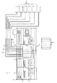
以下、本発明を具体化した第1実施形態を図1〜図9及び図17〜図19に従って説明する。図1は本実施形態の液体噴射装置としてのインクジェット式記録装置(以下、プリンタ1という)の平面図である。
(First embodiment)
Hereinafter, a first embodiment of the present invention will be described with reference to FIGS. 1 to 9 and FIGS. 17 to 19. FIG. 1 is a plan view of an ink jet recording apparatus (hereinafter referred to as a printer 1) as a liquid ejecting apparatus of the present embodiment.
図1に示すように、プリンタ1は、フレーム2を備えている。フレーム2には、プラテン3が架設されており、このプラテン3上には、図示しない紙送り機構により紙が給送される。そして、フレーム2には前記プラテン3と平行にガイド部材4が架設されている。このガイド部材4には、キャリッジ5がガイド部材4の軸線方向に移動可能に挿通支持されている。また、このキャリッジ5は、タイミングベルト6を介してキャリッジモータ7に駆動連結されている。このため、キャリッジ5は、キャリッジモータ7の駆動により、ガイド部材4に沿って往復移動するようになっている。
As shown in FIG. 1, the
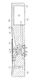
キャリッジ5のプラテン3に対向する面には、液体噴射ヘッドとしての記録ヘッド8が搭載されている。そして、キャリッジ5上には記録ヘッド8に液体としてのインクを供給する6個の液体収容体としてのインクカートリッジ9が搭載されている。キャリッジ5は、インクカートリッジ9を着脱可能であり、図2に示すように、インクカートリッジ9に替えて6個のアタッチメント10を着脱可能に搭載できるようになっている。そして、アタッチメント10をキャリッジ5に搭載した場合、プリンタ1は、インクカートリッジ9が搭載される場合と相違して、外部からのインクの供給を受ける、いわゆるオフキャリッジタイプのプリンタとして機能する。各インクカートリッジ9及びアタッチメント10は、プリンタ1に使用されるインクの色(種類)に対応して6個具備されている。なお、アタッチメント10は、キャリッジ5に設けた記録ヘッド8に対する取り付け形状についてインクカートリッジ9と互換性があり、キャリッジ5にはインクカートリッジ9の代わりにアタッチメント10を着脱可能に搭載することができる。アタッチメント10の詳細については後述する。記録ヘッド8の下面には図示しないノズル吐出口が設けられており、この吐出口から紙上にインク滴が吐出されるようになっている。
A recording head 8 as a liquid ejecting head is mounted on the surface of the
図2において、キャリッジ5にアタッチメント10が搭載された場合、プリンタ1の外側には、前記インクカートリッジ9よりも容積が大きい外部液体収容体としての外部インクタンク11が6個設けられている。外部インクタンク11には、前記インクカートリッジ9よりも多量の各種インクがそれぞれ貯留されており、前記各アタッチメント10と可撓性を有するチューブとしてのインク供給チューブ12を介して接続される。そして、アタッチメント10がキャリッジ5に搭載される際には、これらの外部インクタンク11から各アタッチメント10に各色のインクが供給され、そのインクが記録ヘッド8に供給される。なお、本実施形態では、アタッチメント10、外部インクタンク11、インク供給チューブ12とで液体供給装置を構成している。
In FIG. 2, when the
ここで、各外部インクタンク11として採用可能な構成について、図17〜図19に従って説明する。
(1−1)各外部インクタンク11として、それぞれ内部が気密状態となっている外郭ケースと、その内側に設けられた、図17に示すような液体収容体としてのインクパック225とによって構成することが可能である。すなわちインクパック225は、液体収容部としての袋部236と導出部237とを備える。袋部236は、同じ大きさの2枚の長方形形状を有する第1の可撓性部材としてのラミネートフィルム236aとラミネートフィルム236bとを備え、これらラミネートフィルム236a,236bを重ね合わせて、その4辺の縁を熱溶着することにより袋状に形成されている。また、袋部236の4辺のうちの1つである辺238には、前記導出部237が、各ラミネートフィルム236a,236bに挟まれた状態で熱溶着されている。そして、これにより、袋部236の内部空間は封止されるようになっており、その内部空間にはインクが収容されている。なお、ラミネートフィルム236a,236bは、例えば、ガスバリア性を有するポリエチレンフィルムにアルミニウムを蒸着することにより形成されている。
Here, a configuration that can be adopted as each external ink tank 11 will be described with reference to FIGS.
(1-1) Each external ink tank 11 is constituted by an outer case in which the inside is airtight and an
また、導出部237には、袋部236内部のインクを外部へ流れるのを許容するとともに、その逆のインクの流れを遮断する逆止弁として機能する弁装置を備えている。
このように構成されているインクパック225は、その導出部237にインク供給チューブ12が接続されていない状態においては、インクパック225の弁装置は閉じた状態となっている。従って、この状態においては、インクパック225内のインクは、導出部237を介して外部に流出しないようになっている。
The lead-out
In the
なお、この構造を、インクカートリッジ9のインク容量よりも、例えば、3〜10倍になるように構成して、プリンタ1の外部に設置し、導出部237にインク供給チューブ12を接続することで、外部インクタンク11として利用してもよい。
This structure is configured to be, for example, 3 to 10 times larger than the ink capacity of the
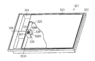
(1−2)各外部インクタンク11として、図18に示すように、液体収容体としてのインクパック321は、上側が開口する液体収容部形成用部材としての箱体322と、同箱体322の上側の開口を閉塞する可撓性部材としてのフィルム材323とによって構成することが可能である。箱体322は、その内部が仕切板322aによって2つに区画されており、第1の部屋324と液体収容用凹部としての第2の部屋325とが形成されている。
(1-2) As shown in FIG. 18, as each external ink tank 11, an
そして、第1の部屋324には、第1の部屋324の中央において横切るようにして、筒体326が形成されている。そして、この筒体326の内部には、図示しないインク流路が設けられており、このインク流路は、箱体322の外部と第2の部屋325とを連通するようにして設けられている。また、筒体326の内部には、図示しない弁装置が設けられている。従って、この筒体326に対して、供給針を挿入させることにより、筒体326の内部に設けられている弁装置が開状態となり、インク供給チューブ12と第2の部屋325とが連通するようになっている。
A
また、第2の部屋には、第1の部屋324の筒体326に隣接するようにして第1の流路形成部材328が設けられている。そして、この第1の流路形成部材328は、箱体322と一体に形成されている。また、第1の流路形成部材328の高さは、前記箱体322の各辺の高さとほぼ等しい高さとなっている。
In the second chamber, a first flow
なお、この構造を、インクカートリッジ9のインク容量よりも、例えば、3〜10倍になるように構成して、プリンタ1の外部に設置し、筒体326にインク供給チューブ12を接続することで、外部インクタンク11として利用してもよい。
This structure is configured to be, for example, 3 to 10 times larger than the ink capacity of the
(1−3)各外部インクタンク11として、図19に示すように、複数のインク収容室を有するインクパック401をケースに収容したインクカートリッジ9として構成することが可能である。すなわち、このインクカートリッジ9の栓体402にインク供給チューブ12を接続して、アタッチメント10と、インクパック401を流体連通させることで、インクカートリッジ9を本実施形態の外部インクタンク11として利用できる。
(1-3) Each external ink tank 11 can be configured as an
図19はインクパック401を示しており、(a)は平面図、(b)は側面図である。なお、説明の便宜上、溶着部は斜線で示す。このインクパック401には、矩形状に形成された可撓性素材が使用されている。このインクパック401は、二枚の長方形の可撓性フィルムを重ね合わせ、それらの長手方向の2辺の縁部(縁辺)が溶着部412,414において、また、短手方向の2辺の縁部が溶着部411,413において、それぞれ所定の幅で帯状に熱溶着されている。インクパック401の短手方向の一方の辺(溶着部411の辺)のほぼ中央部には、インク導出口を構成する栓体402が取り付けられている。この栓体402の内部には、封止部材が充填されており、これによりインクパック401の使用開始時までインクが漏出しないように封入される。
FIG. 19 shows an
また、溶着部412と溶着部414を結ぶように所定の幅で帯状に不完全な溶着がされており、不完全溶着部431及び不完全溶着部432が形成されるとともに、インク収容部421、422、423が区画されている。なお、「不完全な溶着」とは、上下二枚のポリエチレンフィルムが溶着されていない部位(非溶着部分)が残っていることを意味する。そして、この不完全な非溶着部分が、インク収容部421と422、インク収容部422と423との間でインクを流通可能にする連通路451及び452を形成している。
Further, incomplete welding is performed in a band shape with a predetermined width so as to connect the welded
インクカートリッジ9を本実施形態の外部インクタンク11として利用する場合、最下流のインク収容室が、上流側のインク収容室より、重力方向で下側となるにように、インクパックが折りたたまれて、ケースに収容できるのが好ましい。従って、栓体402を支持する栓体挿入部をケースの下側に形成するのが好ましい。なお、本実施形態では、空気導入部を介してインクカートリッジ9の内部に加圧空気が導入される。このため、本実施形態の外部インクタンク11としてインクカートリッジ9を利用する場合、インクカートリッジ9をプリンタ1の外部であって、記録ヘッド8に対して適宜な高さの位置にインクカートリッジ9を配置すれば、加圧空気を導入することなく、単にインクカートリッジ9の内部を空気導入部を介して大気連通するのみで、インクカートリッジ9からインク供給チューブ12を介してアタッチメント10へインクの供給が可能である。
When the
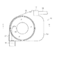
次に、前記アタッチメント10について図3〜図8に従って説明する。
図3は、各色のインクに対応したアタッチメント10の斜視図である。アタッチメント10は、それぞれ個別の分離した構成であってもよいが、図3に示すように互いに連結することでその操作性を向上させている。なお、シアン、マゼンダ、イエロー、ライトシアン、ライトマゼンダの各インクのアタッチメント10も同様な構成なので、以下ではブラックのインクのためのアタッチメント10を説明し、他のインクのアタッチメント10は説明を省略する。
Next, the
FIG. 3 is a perspective view of the
図3及び図4に示すように、アタッチメント10は曲面を有する直方体形状でかつ偏平形状からなる合成樹脂製のユニットケース15を備えている。そして、ユニットケース15は、その上部に形成された接続部17に前記インク供給チューブ12が接続されている。また、ユニットケース15の下部には、連結部としてのインク導出部19が形成されており、このインク導出部19は、キャリッジ5の底面に突設された図示しないインク供給針を介して記録ヘッド8に対して前記インクカートリッジ9の場合と同様に接続される。すなわち、アタッチメント10のインク導出部19は、インクカートリッジ9のインク供給口に対応しているため、インク供給口に利用できる構造が、インク導出部19の構造として利用できる。また、図4に示すように、ユニットケース15は、そのインク導出部19の近辺に、既存のインクカートリッジ9と同様に、記憶手段21が備えられている。
As shown in FIGS. 3 and 4, the
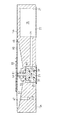
図5は、図4に示すアタッチメント10のa−a線での断面図であって、アタッチメント10に備えられた圧力調整手段を示す。図5に示すように、アタッチメント本体としてのユニットケース15の一側面15aには、略円筒状の小凹部25が形成されている。また、同じく一側面15aには、前記接続部17と連通するインク貯留凹部27が形成されている。インク貯留凹部27には、小凹部25の方向に向かってインク導入路29が形成されており、そのインク導入路29の端部が小凹部25と連通している。この一側面15aには、前記小凹部25を覆う第1のフィルム部材F1が、前記インク貯留凹部27を覆う第2のフィルム部材F2が、熱溶着によってそれぞれ貼り付けられている。そして、小凹部25と第1のフィルム部材F1とによって略円柱状の第1液体供給部、流路としてのインク供給室33が、インク貯留凹部27と第2のフィルム部材F2とによって略円柱状のインク貯留室35が形成されている。従って、インク供給チューブ12から流入するインクは、接続部17、インク貯留室35及びインク導入路29を介してインク供給室33に流入するようになっている。
FIG. 5 is a cross-sectional view taken along line aa of the
また、インク供給室33内には、前記第1のフィルム部材F1側の面に、前記インク供給室33の内径よりも若干小さな外径を有するバネ受け座37が、インク供給室33と同心円状に位置するようにして取り付けられている。そして、バネ受け座37には、前記第1のフィルム部材F1と反対の面に環状の溝部39が設けられている。
Further, in the
また、ユニットケース15の他側面15bには、略円錐台形状の大凹部45が形成されている。なお、この大凹部45は、前記小凹部25よりも大きな径を有しながら前記小凹部25と同心円状に位置するように設けられている。大凹部45の内側面には、一側面15aの方向に向かうようにしてインク導出路47が形成されている。そして、図4に示すように、インク導出路47の端部47aは、前記インク導出部19に形成されている連通孔49と連通している。さらに、図5に示すように、他側面15bには、前記大凹部45を塞ぐようにして、可撓性の第3のフィルム部材F3が熱溶着により貼り付けられている。そして、大凹部45と第3のフィルム部材F3とによって略円錐台形状の第2液体供給部、流路としての圧力室51が形成されている。なお、前記第3のフィルム部材F3は、圧力室51の負圧状態を効率的に感知することができるように軟質であるとともに、インク性状に化学的な影響を及ぼさない材質である。そして、圧力室51内のインクは、インク導出路47及びインク導出部19の連通孔49を介して前記記録ヘッド8に排出されるようになっている。
Further, a large
また、前記第3のフィルム部材F3の前記圧力室51と反対側の面には、第3のフィルム部材F3と比較して硬い材料により形成された円板状の受圧板53が、前記圧力室51に対して同心円状に位置するように、例えば熱溶着によって取り付けられている。この受圧板53は、前記圧力室51の内径よりも小さい外径を有し、ポリエチレンやポリプロピレンといった軽量のプラスチック材料で形成されている。
Further, on the surface of the third film member F3 opposite to the
ユニットケース15のインク供給室33と圧力室51との間には、インク供給室33と圧力室51とを区画するように隔壁55が形成されており、この隔壁55には、インク供給室33と圧力室51とを連通させる開閉弁を構成する支持孔57が形成されている。そして、この支持孔57には、開閉弁を構成する可動バルブ59が摺動可能に挿通支持されている。可動バルブ59は、詳しくは、円柱状のロッド部材61と、このロッド部材61に一体に形成されている断面円形の板状部材63とにより構成されている。
A
そして、板状部材63は、インク供給室33側に配設され、その外径は前記ロッド部材61の外径よりも大きくなっている。板状部材63から延びるロッド部材61は、前記支持孔57に摺動可能に挿通支持され、その先端が圧力室51に突出するようになっている。
The
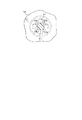
なお、図6に示すように、前記支持孔57は、等間隔に4つの切欠き溝57aが形成されている。従って、支持孔57にロッド部材61が挿通支持された状態では、ロッド部材61と切欠き溝57aとによって、4つのインク流路57bが形成されるようになっている。また、図5に示すように、板状部材63は、環状の段差部63aが形成され、その段差部63aと前記バネ受け座37の溝部39との間に、コイルばね65が配設されている。このコイルばね65の作用により、板状部材63は常に隔壁55側に付勢されている。
As shown in FIG. 6, the
一方、図5及び図6に示すように、インク供給室33側の隔壁55には、前記支持孔57を囲むようにして円環状に形成されたゴム製のシール部材67が取り付けられている。従って、可動バルブ59における前記板状部材63は、コイルばね65の付勢力によりシール部材67に当接するようになっている。そして、板状部材63とシール部材67とが当接する場合には、前記4つのインク流路57bは閉じた状態、すなわち、インク供給室33と圧力室51との間が遮断される。反対に、コイルばね65の付勢力に抗して板状部材63が第1のフィルム部材F1側に移動してシール部材67から離間すると、インク供給室33と圧力室51とが連通する。
On the other hand, as shown in FIGS. 5 and 6, a
なお、シール部材67は、ユニットケース15を形成するときに、二色成形により隔壁55に一体的に形成されるのが好ましい。また、同様の方法で、シール部材67は、隔壁55ではなく、可動バルブ59の板状部材63に形成されて、隔壁55に接触離間するようにしてもよい。
The
そして、以上のように構成されたアタッチメント10は、前記記録ヘッド8が非印刷状態、すなわちインクを消費しない状態においては、前記コイルばね65によるバネ荷重W1が、可動バルブ59の前記板状部材63に加わっている。また、板状部材63にはインク供給室33に供給されるインクの加圧力P1も加わる。これにより、前記板状部材63は図5に示したように、ゴム製のシール部材67に当接し、前記インク流路57b(図6参照)は閉弁状態になる。すなわち、インク供給室33と圧力室51との間は非連通の状態となり、アタッチメント10は自己封止の状態になる。
In the
一方、前記記録ヘッド8が印刷状態となり、インクを消費した場合においては、圧力室51のインクの減少に伴い圧力室51が負圧となり、前記第3のフィルム部材F3がインク供給室33側に変位し、第3のフィルム部材F3の中央部が可動バルブ59を構成するロッド部材61の端部に当接する。なお、この時、第3のフィルム部材F3の変位に要する変位反力をWdとする。そして、記録ヘッド8においてさらにインクが消費されることにより、圧力室51内には負圧P2が発生するようになる。そしてこの時、P2>W1+P1+Wdの関係となった場合に、第3のフィルム部材F3がロッド部材61を押圧し、これにより、板状部材63とシール部材67との当接が解かれ、図7に示すように、インク流路57b(図6参照)は開弁状態となる。そして、インク供給室33内におけるインクは、インク供給室33から圧力室51に至るインク流路57bを介して圧力室51内に供給される。
On the other hand, when the recording head 8 is in a printing state and consumes ink, the
つまり、インク供給室33に供給されるインクの加圧力P1が大きくなっても、圧力室51内にそれを上回る負圧P2が発生しなければ閉弁状態のままとなる。すなわち、圧力室51内におけるインクの圧力変動は、可動バルブ59の開閉によって、ある一定の範囲内となるように制限されており、インク供給室33内のインクの圧力変化とは切り離されている。従って、外部インクタンク11の設置場所やそのインクの残量により、外部インクタンク11のインクの液面が変動し、インク供給室33内のインクの圧力に変動が生じていても、その影響を受けることがない。その結果、圧力室51から記録ヘッド8へ吐出されるインク滴の重量は一定となるため、印字品質が一定になる。
That is, even if the pressure P1 of the ink supplied to the
そして、圧力室51内へインクが流入すると、圧力室51の負圧P2は解消され、P2<W1+P1+Wdとなる。これに伴い、可動バルブ59が移動して図5に示すように再び閉弁状態になされ、インク供給室33から圧力室51へのインクの供給は停止される。
When ink flows into the
なお、前記した可動バルブ59の開閉弁の動作は、図5及び図7に示す状態が、反復繰り返されるような極端な動作が必ずしもなされる必要はない。現実には印刷動作中においては、第3のフィルム部材F3は可動バルブ59を構成するロッド部材61の端部に当接した均衡状態を保ち、インクの消費に従って僅かに開弁しつつ、圧力室51に対してインクを逐次補給するように作用する。
The operation of the opening / closing valve of the
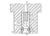
次に、インク導出部19に備えられた開閉弁としての弁機構Vについて図4及び図8に従って説明する。
図4に示すように、インク導出部19には、前記インク導出路47を介して圧力室51と連通する連通孔49が開口している。図8に示すように、インク導出部19は、連通孔49と連通する弁孔19aと導出孔19bが形成されている。弁孔19aは、その内周面に複数の連通溝19cが形成されている。ここでは、連通溝19cは、弁孔19aの内周面の2箇所に形成されている。導出孔19bは、外部に開放され、弁孔19aの内径より大きい内径である。
Next, the valve mechanism V as an on-off valve provided in the
As shown in FIG. 4, the
また、インク導出部19に形成した弁孔19a及び導出孔19bには、弁機構Vが備えられている。弁機構Vは、弁体70とシール部材72とを備えている。弁体70の外径は、弁孔19aの内径とほぼ同じ大きさとなっており、その弁孔19aの中心軸線方向に摺動可能に配設されている。
In addition, a valve mechanism V is provided in the valve hole 19 a and the outlet hole 19 b formed in the
シール部材72は、導出孔19bに嵌着されている。シール部材72は、エラストマ等の可撓性材質からなり、略円筒状に形成されている。シール部材72の中心を貫通する挿
入孔72aは、弁体70側の内径が、キャリッジ5の底面に備えられた図示しないインク供給針がしまり嵌めとなる径であって、その導出側に向かうに従って拡開形成されている。シール部材72の基端面72bには、前記挿入孔72aの開口を囲むように弁座74が突設されている。この弁座74に前記弁体70が着座することによって、シール部材72の挿入孔72aは同弁体70にて閉塞される。尚、前記インク供給針は、中空状に形成されており、その孔を介してインクを内部に流入するようになっている。
The seal member 72 is fitted into the outlet hole 19b. The seal member 72 is made of a flexible material such as an elastomer and is formed in a substantially cylindrical shape. The
さらに、弁機構Vは、弁体70を付勢するコイルバネ76を備えている。コイルバネ76は、弁孔19a内に、弁体70をシール部材72側に付勢するように支持固定されている。外部から力が加えられていない場合には、図8に示すように、コイルバネ76は弁体70をシール部材72の弁座74に圧接するように付勢する。そして、シール部材72の挿入孔72aを介して弁体70にインク供給針が挿入されると、弁体70はコイルバネ76の付勢力に抗してシール部材72から離間する方向に移動する。このとき、インク供給針の先端はシール部材72にシールされた状態で挿入されている。また、弁体70がシール部材72から離間すると、前記インク供給針の孔と、弁体70を挟んで反対側の弁孔19aと前記連通溝19cとがつながる。従って、圧力室51内のインクがインク導出部19に導入されると、インクは連通溝19cを介して弁体70を挟んでシール部材72側の弁孔19aに導かれ、前記インク供給針の孔から記録ヘッド8に流入する。
Further, the valve mechanism V includes a coil spring 76 that urges the
次に、上記のように構成したプリンタ1の電気的構成を図9に従って説明する。
図9において、プリンタ1は、CPU81、ROM82、RAM83、インタフェイス84、印刷回路部85、読み取り回路部86を備えている。
Next, the electrical configuration of the
In FIG. 9, the
CPU81は、ROM82に記憶されたプログラムに従ってインタフェイス84を介して外部装置から印刷データ等を入力し、RAM83に一時記憶する。また、CPU81は、ROM82に記憶されたプログラムに従って、RAM83に記憶された印刷データに基づいて印刷回路部85を制御してキャリッジ5、記録ヘッド8等を駆動させて印刷用紙にインクを吐出する。また、CPU81は、読み取り回路部86を介して、キャリッジ5に搭載されたインクカートリッジ9に設けた記憶手段(図示しない)に記憶しているデータ(液体情報)の授受を行う。インクカートリッジ9に設けた記憶手段(図示しない)に記憶される情報には、インクカートリッジ9の総インク量、インクの消費量、インクの残量、及びインクの色などのインクの属性情報と、インクカートリッジ9の種類、取り付けられた回数及び製造年月日などのデータがある。CPU81は、インクカートリッジ9のインクを使って印刷を行うとき、印刷を行う毎に、読み取り回路部86を介して、公知の方法で記憶手段の内容を更新する。
The
また、CPU81は、読み取り回路部86を介して、キャリッジ5に搭載されたアタッチメント10に設けた記憶手段21に記憶しているデータ(液体情報)の授受を行う。アタッチメント10に設けた記憶手段21に記憶される液体情報には、外部インクタンク11の総インク量、インクの消費量、インクの残量、及びインクの色などのインクの属性情報と、外部インクタンク11の種類、取り付けられた回数及び製造年月日などのデータがある。CPU81は、外部インクタンク11のインクを使って印刷を行うとき、印刷を行う毎に、読み取り回路部86を介して前記インクカートリッジ9の場合と同様に記憶手段21の内容を更新する。
In addition, the
次に、このように構成されたアタッチメント10及びプリンタ1の作用について説明する。
インクカートリッジ9に替えて外部インクタンク11を使用して印刷する場合、ユーザは、まずキャリッジ5にアタッチメント10を装着し、インク供給チューブ12を介してそのアタッチメント10と外部インクタンク11を接続する。アタッチメント10は記録ヘッド8に対する取り付け形状が前記インクカートリッジ9と互換性があるため、インクカートリッジ9に替えてキャリッジ5に搭載することができる。そして、記録ヘッド8からインク滴が噴射されて印刷が行われると、外部インクタンク11からインクがアタッチメント10に供給され、そのアタッチメント10に供給されたインクはキャリッジ5を介して記録ヘッド8に供給される。
Next, the operation of the
When printing using the external ink tank 11 instead of the
このとき、アタッチメント10において、インク供給室33と圧力室51との間に、可動バルブ59、コイルばね65、シール部材67等からなる圧力調整手段を設けた。そのため、外部インクタンク11を置く場所(外部インクタンク11のインクの液面)は、記録ヘッド8よりも高い、すなわち水頭差のある場所であってもよい。従って、キャリッジ5から離間して外部インクタンク11を置く場所の自由度が高くなる。また、インク導出部19に弁機構Vを設けたので、アタッチメント10を記録ヘッド8から取り外したり、プリンタ1を持ち運んだりしてアタッチメント10の姿勢が変化するときにも、インクが漏れたり、アタッチメント10からインク供給チューブ12、外部インクタンク11に空気が侵入したりすることがない。
At this time, in the
プリンタ1は、外部インクタンク11のインクを使って印刷を行っているとき、その時々でインクの消費量を算出するが、そのインクの消費量とアタッチメント10に設けた記憶手段21の情報とで、外部インクタンク11のインクの残量を求めることができる。そして、プリンタ1は、このインク残量のデータに基づいて、インクカートリッジ9のインクを使って行う印刷と同様な効率のよい印刷を行うことができる。
When the
上記実施形態によれば、以下のような効果を得ることができる。
(1)本実施形態によれば、記録ヘッド8に対する取り付け形状が前記インクカートリッジ9と互換性のあるアタッチメント10に可動バルブ59、コイルばね65、シール部材67等からなる圧力調整手段(弁装置)を設けた。従って、外部インクタンク11のインクの残量に関係なく、常に一定の圧力のインクを記録ヘッド8に供給することができるため、印字品質を一定に保つことができる。
According to the above embodiment, the following effects can be obtained.
(1) According to the present embodiment, the pressure adjusting means (valve device) includes the
(2)本実施形態によれば、アタッチメント10に設けた可動バルブ59、コイルばね65、シール部材67等からなる圧力調整手段(弁装置)によって、アタッチメント10の圧力室51は、内部のインクの減少にしたがってインク供給室33からインクの供給を受けるようになっている。そのため、圧力室51内におけるインクの圧力変動は、ある一定の範囲内となるように制限されている。つまり、インク供給室33に供給されるインクの加圧力P1が大きくなっても、圧力室51内にそれを上回る負圧P2が発生しなければ閉弁状態のままとなるので、圧力室51より上流(外部インクタンク11側)において圧力変動が生じていても、記録ヘッド8がその影響を受けることがない。その結果、外部インクタンク11の設置場所やそのインクの残量により、外部インクタンク11のインクの液面が変動し、インク供給室33内のインクの圧力に変動が生じていても、その影響を受けることがないため、外部インクタンク11の設置場所の自由度が増す。
(2) According to the present embodiment, the
(3)本実施形態によれば、記録ヘッド8に対する取り付け形状が前記インクカートリッジ9と互換性のあるアタッチメント10をキャリッジ5に搭載したので、インクカートリッジ9よりもインク貯留量の多い外部インクタンク11からのインクを記録ヘッド8に供給することができる。従って、インクカートリッジの交換の手間及びランニングコストを低減することができる。
(3) According to the present embodiment, since the
(4)本実施形態によれば、アタッチメント10に記憶手段21を設けたので、インクカートリッジ9の替わりにアタッチメント10をキャリッジ5に搭載しても、インクの属性情報や外部インクタンク11の情報等を正しく認識することができるため、インクカートリッジ9をキャリッジ5に搭載したときと同様に正常に印刷することができる。
(4) According to the present embodiment, since the storage means 21 is provided in the
なお、第1実施形態を以下のように変更してもよい。
○図12に示すように、ユニットケース15の一側面15aに溝30を形成し、この溝30を、小凹部25とインク貯留凹部27とを覆う単一のフィルムFで覆うようにして、インク導入路29を形成してもよい。なお、フィルムFは、第1及び第2のフィルム部材F1,F2と同様に、熱溶着で一側面15aに貼り付けられるのが好ましい。このように構成することで、インク導入路29を容易に形成することができる。
Note that the first embodiment may be modified as follows.
As shown in FIG. 12, a
○第1実施形態では、外部インクタンク11に書き換え可能な記憶手段21を設け、インク残量を外部インクタンク11の記憶手段21に記憶する場合を説明したが、これに替えて、外部インクタンク11に、読み出し専用の記憶手段(ROM)を設けてもよい。この場合、外部インクタンク11のROMには、外部インクタンク11に固有の識別番号(ID)を記憶しておく。そして、ドットカウント等の公知の手段で算出したインクの消費量からインク残量を算出し、このインク残量と、外部インクタンク11のROMから読み出した識別番号とを関連付けて、プリンタメモリに記憶して、プリンタ1でインク残量を管理することが可能である。
In the first embodiment, the case where the
ここで、インク消費量からインク残量を最初に算出するために必要な総インク量(初期インク量)は、以下の方法で得ることが好ましい。
すなわち、アタッチメント10、インク供給チューブ12及び外部インクタンク11が一体的であって、外部インクタンク11のみの交換ができない構造の場合は、これらに収容されるすべてのインク量を、総インク量として、外部インクタンク11のROMに記憶しておくことで、読み取り回路部86等を使用してプリンタ1が総インク量を把握することができる。
Here, it is preferable to obtain the total ink amount (initial ink amount) necessary for first calculating the remaining ink amount from the ink consumption amount by the following method.
That is, in the case where the
また、外部インクタンク11が、インク供給チューブ12から取り外し可能で、外部インクタンク11のみの交換が可能な場合は、図13に模式的に示すように、外部インクタンク11にもROMを持たせ、このROMに外部インクタンク11の総インク量を記憶させてもよい。外部インクタンク11をインク供給チューブ12と接続する際に、インク供給チューブ12に沿って伸長し、かつ、アタッチメント10の記憶手段21(基板)に設けられた電極に電気接続されたフレキシブルケーブルFPCまたは電線のコネクタC1を、外部インクタンク11の外周面に設けられ、かつ、外部インクタンク11のROMに接続されたコネクタC2に接続する。これにより、プリンタ1は、外部インクタンク11のROMから、フレキシブルケーブルFPCまたは電線、記憶手段21(基板)の電極、読み取り回路部86等を介して、外部インクタンク11の総インク量についてのデータを把握することができる。このようにして得られた外部インクタンク11の総インク量と、アタッチメント10のROMに記憶されたアタッチメント10の総インク量とを加算することで、プリンタ1は、アタッチメントシステム全体の総インク量を把握できる。
When the external ink tank 11 can be removed from the
○なお、上記の各ハードウエアを設ける代わりに、以下のような方法を採ることも可能である。インタフェイス84に接続可能な外部装置の一つであるPC(パーソナル・コンピュータ)にインストール可能なプリンタドライバを利用して、PC上に総インク量入力画面を表示させる。ユーザは、外部インクタンク11に添付されたラベル上に表示された外部インクタンク11の総インク量や、外部インクタンク11とともに梱包されているマニュアルに表示された外部インクタンク11の総インク量を読み取り、PCの入力装置及び総インク量入力画面を利用して、外部インクタンク11の総インク量を、PCに入力し、プリンタドライバ、インタフェイス84を介して、プリンタ1に総インク要を提供する。これにより、プリンタ1は、外部インクタンク11の総インク量を把握できる。
In addition, instead of providing each hardware described above, the following method can be adopted. A total ink amount input screen is displayed on the PC using a printer driver that can be installed on a PC (personal computer) which is one of external devices connectable to the
○本実施形態のアタッチメントシステムの場合、全体の総インク量は、インクカートリッジ9の総インク量に比べ、例えば、3倍から10倍と大きいので、ドットカウント等のソフトウエアによるインク残量の検出において、誤差が生じる可能性がある。従って、このインク残量検出中に、キャリブレーションを行うことが好ましい。例えば、図14に模式的に示すように、アタッチメント10の内部に、一対の電極やピエゾセンサ等の公知の液面センサSを配置する。この液面センサを利用して、外部インクタンク11のインクがすべて消費され、さらに、アタッチメント10のインクが一部消費されて、アタッチメント10内のインク残量が予め決められた量(所定量)となった時点での液面を検出する。この時点で、今まで行っていたソフトウエアカウントでのインク残量の値をクリアし、新たに当該所定量からのソフトウエアカウントによるインク残量算出を行う。これにより、アタッチメント10のインクが所定量になるまでに、ソフトウエアカウントで蓄積される可能性がある算出誤差を修正することができる。この所定量は、記憶手段21に予め記憶されており、また、液面センサSの出力は、例えば、記憶手段21の基板に設けられた電極を介して、プリンタに出力可能に構成されている。従って、プリンタ1は、読み取り回路部86等を介して、この所定量及びアタッチメント10内のインク残量がこの所定量となった時点を把握できる。なお、このような液面センサSをアタッチメント10に配置する場合、アタッチメント10のインクが、所定量になるまでに、ソフトウエアカウントを実行しなくてもよい。従って、外部インクタンク11の総インク量をプリンタが把握するための手段を省略することもできる。
(第2実施形態)
次に、本発明を具体化した第2実施形態を図10に従って説明する。本実施形態では、第1実施形態で説明した圧力調整手段(弁装置)の構成に特徴を有するので、以下の実施形態において、前記第1の実施形態と同様の部分については、同一の符号を付し、その詳細な説明は省略する。
In the case of the attachment system of the present embodiment, the total ink amount as a whole is, for example, 3 to 10 times larger than the total ink amount of the
(Second Embodiment)
Next, a second embodiment of the present invention will be described with reference to FIG. In this embodiment, since it has the characteristic in the structure of the pressure adjustment means (valve apparatus) demonstrated in 1st Embodiment, in the following embodiment, the same code | symbol is attached | subjected about the part similar to the said 1st Embodiment. A detailed description thereof will be omitted.
図10は、アタッチメント10の要部断面図を示す。
図10に示すように、ユニットケース15の一側面15aには、略円筒状の第1の凹部95が形成されており、第1の凹部95は、前記接続部17と連通している。そして、この一側面15aには、前記第1の凹部95を覆うフィルム部材97が熱溶着によって貼り付けられている。従って、第1の凹部95とフィルム部材97とによって略円柱状の第1液体供給部、流路としてのインク供給室99が形成されている。そして、インク供給チューブ12から流入するインクは、接続部17を介してインク供給室99に流入するようになっている。
FIG. 10 is a cross-sectional view of the main part of the
As shown in FIG. 10, a substantially cylindrical first
また、図10に示すように、ユニットケース15の他側面15bには、略円筒状の第2の凹部101が形成されており、第2の凹部101は、前記インク導出部19と連通している。そして、この他側面15bには、前記第2の凹部101を覆うフィルム部材103が熱溶着によって貼り付けられている。従って、第2の凹部101とフィルム部材103とによって略円柱状の第2液体供給部、流路としてのインク導出室105が形成されている。
As shown in FIG. 10, the other side surface 15 b of the
そして、前記インク供給室99とインク導出室105を区画する隔壁107には、複数の貫通孔109が形成されている。また、隔壁107の中央位置には、インク導出室105に突出した支持凸部111が形成されている。
A plurality of through
インク導出室105内には、前記フィルム部材103側の面に、前記インク導出室105の内径よりも若干小さな外径を有するバネ受け座113が、インク導出室105と同心円状に位置するようにして取り付けられている。そして、バネ受け座113の中心部には、前記フィルム部材103と反対の面に凹部115が設けられている。また、バネ受け座113の外周端部であって、前記フィルム部材103と反対の面には、環状の凸部117が突設されている。
In the
バネ受け座113と前記隔壁107との間には、円筒状の弁収容筒部119が配設されている。弁収容筒部119は、その内部の嵌合部121を拡開形成し、その嵌合部121に膜弁123が嵌合されている。そして、膜弁123は、バネ受け座113と弁収容筒部119との間に挟持固定された環状の抜け止めリング125によって、弁収容筒部119から抜け出さないように支持されている。膜弁123は、エラストマ等の弾性変形可能な材料によって形成され、前記支持凸部111と対向する中央位置には凸部127が形成されている。凸部127の中心には円柱形状の貫通孔129が形成されている。膜弁123は、同膜弁123を境にインク導出室105をバネ受け座113側と隔壁107側とに区画する。そして、支持凸部111に凸部127が当接すると、凸部127に形成した貫通孔129が支持凸部111に塞がれてインク導出室105のバネ受け座113側と隔壁107側とが遮断、すなわち、インク導出室105とインク供給室99とが非連通状態となる。
A cylindrical valve
反対に、支持凸部111に対して凸部127が離間すると、凸部127に形成した貫通孔129が開放されてインク導出室105のバネ受け座113側と隔壁107側とが連通、すなわち、インク導出室105がインク供給室99と連通状態となる。
On the other hand, when the
前記インク導出室105内であって、バネ受け座113の凹部115と膜弁123の凸部127との間にはコイルばね133が介在している。そして、コイルばね133によって膜弁123の貫通孔129が、支持凸部111に向かって当接するように付勢されている。従って、外部から何も力が加わっていない状態においては、貫通孔129は、支持凸部111によって閉塞される状態となっている。なお、本実施形態では、支持凸部111、膜弁123、コイルばね133によって弁装置が構成されている。
A
そして、以上のように構成されたアタッチメント10は、前記記録ヘッド8が非印刷状態、すなわちインクを消費しない状態においては、前記コイルばね133によるバネ荷重W1とインク供給室99内のインクの加圧力P3とインク導出室105内のインク圧力P4が、膜弁123に加わっている。これにより、前記膜弁123は図10に示したように、支持凸部111に当接し、前記貫通孔129は閉弁状態になる。すなわち、インク供給室99とインク導出室105との間は非連通の状態となり、アタッチメント10は自己封止の状態になる。
The
一方、前記記録ヘッド8が印刷状態となり、インクを消費した場合においては、インク導出室105のインクの減少に伴い、インク導出室105内のインク圧力P4がインク供給室99内のインクの加圧力P3より減少していく。なお、この時の膜弁123の変位に要する変位反力をWdとする。そして、記録ヘッド8においてさらにインクが消費されることにより、インク導出室105内のインク圧力P4がさらに減少する。そしてこの時、|P3―P4|>W1+Wdの関係となった場合に、膜弁123が支持凸部111から離間し、インク供給室99とインク導出室105との間は連通の状態となる。
On the other hand, when the recording head 8 is in a printing state and consumes ink, the ink pressure P4 in the
従って、インク供給室99内におけるインクは、インク供給室99から貫通孔129を介してインク導出室105内に供給され、インク導出室105内へのインクの流入によりインク導出室105の負圧は解消される。これに伴い、膜弁123が移動して図10に示すように再び閉弁状態になされ、インク供給室99からインク導出室105へのインクの供給は停止される。
Accordingly, ink in the
つまり、インク供給室99に供給されるインクの加圧力P3とインク導出室105内のインク圧力P4とに差圧が生じ、その差圧がコイルばね133によるバネ荷重W1と膜弁123の変移に要する変位反力Wdとの和を上回らなければ閉弁状態のままとなる。すなわち、インク導出室105内におけるインクの圧力変動は膜弁123の開閉によって、ある一定の範囲内となるように制限されている。そして、インク供給室99内のインクの圧力とインク導出室105内のインクの圧力との差圧がコイルばね133によるバネ荷重W1と膜弁123の変移に要する変位反力Wdとの和以下であれば、インク供給室99内のインクの圧力に変動が生じていても、インク導出室105は、その影響を受けることがない。その結果、インク導出室105から記録ヘッド8へ吐出されるインク滴の重量は一定となるため、印字品質が一定になる。
In other words, a differential pressure is generated between the pressure P3 of the ink supplied to the
上記実施形態によれば、第1実施形態の(3)、(4)に加えて以下の効果を得ることができる。
(1)本実施形態によれば、記録ヘッド8に対する取り付け形状が前記インクカートリッジ9と互換性のあるアタッチメント10に支持凸部111、膜弁123、コイルばね133等からなる圧力調整手段(弁装置)を設けた。従って、一定の圧力のインクを記録ヘッド8に供給することができるため、印字品質を一定に保つことができる。
(第3実施形態)
次に、本発明を具体化した第3実施形態を図11に従って説明する。本実施形態では、第1及び第2実施形態で説明した圧力調整手段の構成に特徴を有するので、以下の実施形態において、前記第1及び第2の実施形態と同様の部分については、同一の符号を付し、その詳細な説明は省略する。
According to the said embodiment, in addition to (3) and (4) of 1st Embodiment, the following effects can be acquired.
(1) According to the present embodiment, pressure adjusting means (valve device) comprising an
(Third embodiment)
Next, a third embodiment of the present invention will be described with reference to FIG. In this embodiment, since it has the characteristic in the structure of the pressure adjustment means demonstrated in 1st and 2nd embodiment, in the following embodiment, about the part similar to the said 1st and 2nd embodiment, it is the same. Reference numerals are assigned and detailed description thereof is omitted.
図11は、アタッチメント10の一部断面図を示す。
図11に示すように、アタッチメント10のユニットケース15は、その内部にインクを貯留するためのインク供給室140を備えており、図示しない外部インクタンク11のインクがインク供給チューブ12を介して接続部17から導入され、インク導出部19から記録ヘッド8にインクを供給する。
FIG. 11 is a partial cross-sectional view of the
As shown in FIG. 11, the
そのインク供給室140には、多孔質部材としての多孔質体142が収容されている。多孔質体142は、外部インクタンク11からのインクを一時保持し、その保持したインクをインク導出部19から記録ヘッド8に供給する。アタッチメント10は、この多孔質体142の毛細管力により、アタッチメント10内のインクの圧力が記録ヘッド8の圧力よりも若干低くなる。従って、記録ヘッド8からインクが垂れ流れるのを低減するので、アタッチメント10から記録ヘッド8へ吐出されるインク滴の重量は一定となり、印字品質を一定にすることができる。
The
図11に示されるように、接続部17は、アタッチメント10内部に突出しており、多孔質体142のA部を圧縮している。同様に、インク導出部19もアタッチメント10内部に突出しており、多孔質体142のB部を圧縮している。多孔質体142のB部での圧縮率は、多孔質体142のA部での圧縮率より高くなっているため、多孔質体142のB部での毛細管力は、多孔質体142のA部での毛細管力より高くなっている。
As shown in FIG. 11, the
記録ヘッド8によりアタッチメント10内のインクが消費されると、外部インクタンク11と記録ヘッド8との水頭差と、多孔質体142のA部での毛細管力との相互作用により、外部インクタンク11のインクが、アタッチメント10内に補充される。多孔質体142のB部が、多孔質体142の中で最も高い毛細管力を有するので、記録ヘッド8でのインクの消費に伴い、外部インクタンク11のインクが、インク導出部19へスムーズに流れる。
When the ink in the
そして、外部インクタンク11のインクがすべて消費されると、圧縮率がやや高いA部でインクが保持されつつ、アタッチメント10内のインク(多孔質体142に吸収されているインク)が、記録ヘッド8でのインクの消費に伴い、インク導出部19へスムーズに流れる。
When all the ink in the external ink tank 11 is consumed, the ink in the attachment 10 (ink absorbed by the porous body 142) is retained in the recording head while the ink is held in the portion A having a slightly high compression rate. As the ink is consumed at 8, the ink flows smoothly to the
従って、アタッチメント10内のインクが、記録ヘッド8で消費される過程で、圧縮率が高いA部で、常にインクが保持されているので、インク供給チューブ12を介して、空気が外部インクタンク11に逆流することが防止できる。特に、外部インクタンク11が、インク供給チューブ12から取り外し可能で、外部インクタンク11のみを交換できる構造の場合に、インク供給チューブ12内に気泡が混入していない。このため、新しい外部インクタンク11をインク供給チューブ12に接続するだけで、外部インクタンク11とアタッチメント10とが、インク供給チューブ12のインクを介して連通可能となる。
Accordingly, since the ink in the
ユニットケース15の上部内側面には、複数のフィン144が突設され、複数のフィン144にて前記多孔質体142の上面を支持固定し、インク供給室140の上側部分に若干隙間を形成するようになっている。
A plurality of
ユニットケース15の上面には、凹部146が凹設され、その凹部146の底面一側には、インク供給室140と連通する貫通孔148が形成されている。また、ユニットケース15の上面には、凹部146を閉塞するようにフィルム部材150がユニットケース15に対して熱溶着にて貼り付けられている。フィルム部材150には、前記貫通孔148から最も離間した位置に大気連通孔152が形成され、この大気連通孔152と、凹部146及び貫通孔148とから大気連通路154が形成されている。大気連通路154は、前記貫通孔148と前記大気連通孔152とが離間した位置に設けられているため、その流路長を長細くできる。その結果、インク供給室140内のインクの蒸発を抑えることができる。
A
上記実施形態によれば、アタッチメント10内に多孔質体142を収容したので、第1及び第2実施形態に比べて、その構成が非常に簡単かつ安価に形成することができる。
また、上記実施形態によれば、アタッチメント10内に配置された多孔質体142内でのインクの流れを最適化できる。
(第4実施形態)
次に、本発明を具体化した第4実施形態を図15及び図16に従って説明する。本実施形態のアタッチメント10も、インクカートリッジの代わりに、このインクカートリッジを装着するためのキャリッジに装着されるものである。アタッチメント10の外部構造は、キャリッジに装着可能とするために、インクカートリッジの外部構造と同一となっている。
According to the above embodiment, since the
Further, according to the embodiment, the ink flow in the
(Fourth embodiment)
Next, a fourth embodiment embodying the present invention will be described with reference to FIGS. The
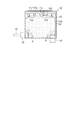
アタッチメント は、容器本体502aと、蓋体502bとからなる扁平な容器と、容器本体502aの1つの壁面(底壁503)に記録ヘッドの流路形成部材を構成するインク供給針と係合してインクを供給する液体導出部としてのインク導出部19を設けて構成されている。なお、インク導出部19は、カートリッジの長手方向の中央部よりも一側に偏する位置(つまり係止部材であるレバー509が形成された壁面(第1側壁という)の側)に配置されていて、インク導出部19の先端側に付勢力を発揮するバネにより常時閉弁状態を維持する弁体が装着され、その外側、つまり先端側に流路形成部材と係合する環状の弾性シール材が装填されている。
The attachment engages with a flat container composed of a
インク導出部19が形成されている壁面503に略直交し、かつ相対向する2つの壁面507,508の、前記インク導出部19に近い側の壁面507には、弾性変形可能な係合部であるレバー509が形成されている。レバー509は、下部を回動支点509aとし、かつ弾性変形可能に容器本体502aの壁面507に設けられていて、回動支点509aよりも上部にはキャリッジ5の係合部に着脱可能な係合部である爪部519が外側に突出するように形成され、回動支点509aと爪部519との間に、レバー本体から側方に突出するように突起520が、好ましくは両側にそれぞれ形成されている。
A
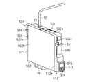
また他方の壁面508には、キャリッジ5の装填レバーが押圧可能な位置にレバー受圧部及び凸部511が形成されている。凸部511の下方にはカートリッジの壁面508(第2側壁という)よりも突出し、両側を記録装置に規制されかつ装填方向(インク供給口の軸方向)に平行となる面513,512a,512bを有する凸部512が形成され、ここに記録装置の弾性接点部材とコンタクトを形成する電極514が複数、この実施形態では水平方向に複数並ぶように上下2段に千鳥状に形成されている。
On the
壁面508は幅方向に狭い為、縦長形状に形成することで所要面積を確保した電極を縦横共に複数列で配置し、アタッチメント501の左右方向位置決め部として機能する面512a,512bの近傍で位置決め精度の高い領域に集中的に電極514を配置することができる。
Since the
この電極514は、回路基板515を凸部512の面513に固定することにより形成されている。なお、回路基板515の裏面には、インク容器に収容されているインクの情報を格納したEEPROM等の読み書き可能な半導体記憶素子等の記憶手段が実装され、電極514に導電的に接続されている。
The electrode 514 is formed by fixing the
複数の電極514を配した回路基板515の表面の上方への仮想延長面から大きく外れない位置でアタッチメント501を下方へ位置決めする力を受ける凸部511を設け、カートリッジ装填時によじれによる電極514の位置決め不良を防ぎ、正確な電極514と弾性接点部材とのコンタクトを実現している。
A
本実施形態では、構成を簡単にするため、アタッチメント10の内部には、第3実施形態と同様に、多孔質体142を配置している。また、第3実施形態と同様に、接続部17は、アタッチメント501内部に突出しており、多孔質体142のA部を圧縮している。インク導出部19もアタッチメント501内部に突出しており、多孔質体142のB部を圧縮している。多孔質体142のB部での圧縮率は、多孔質体142のA部での圧縮率より高くなっているため、多孔質体142のB部での毛細管力は、多孔質体142のA部での毛細管力より高くなっている。
In the present embodiment, in order to simplify the configuration, the
外部インクタンク11は、前記(1−1)〜(1−3)のように様々な構造を採用可能である。その一例として、前記(1−1)のインクパック225を、設置及び交換の便宜を考慮して、蓋とケース本体とからなるケースに、取り外し可能に装着した構造を、模式的に図16に図示する。
The external ink tank 11 can employ various structures as described in (1-1) to (1-3). As an example, FIG. 16 schematically shows a structure in which the
なお、多孔質体142の替わりに、アタッチメント50の内部に、第1,2実施形態の弁装置を設けたり、その他の形状のインク流路及び弁装置を設けたりしてもよい。
本実施形態においても、第3実施形態と同様の効果が得られる。
Instead of the
Also in this embodiment, the same effect as the third embodiment can be obtained.
なお、上記各実施形態は以下のように変更してもよい。
○上記各実施形態では、大容量の外部インクタンク11を使用するので、長期間にわたってアタッチメントシステムが外部にさらされることとなる。従って、インクの特性やインクの脱気度の変化を防止するために、アタッチメントシステムにガスバリア性を持たせることが望まれる。例えば、外部インクタンク11に良好なガスバリア性を持たせるには、図17に示するような、いわゆるパック形態のインクパックを使用するのが好ましく、インクパックを形成するフィルムとして、例えば、ポリプロピレン(PP)、ポリエチレン(PE)、または液晶ポリマーなどで形成したものや、ポリエチレンフィルムの表面にアルミニウムを蒸着したものを使用するのが好ましい。また、インク供給チューブ12に良好なガスバリア性を持たせるには、ナイロンや塩化ビニリデン、またはこれらの層を含む多層構造で構成するのが好ましい。
In addition, you may change each said embodiment as follows.
In each of the above embodiments, since the large-capacity external ink tank 11 is used, the attachment system is exposed to the outside for a long period of time. Therefore, in order to prevent changes in ink characteristics and ink deaeration, it is desirable to provide the attachment system with a gas barrier property. For example, in order to give the external ink tank 11 good gas barrier properties, it is preferable to use a so-called pack-type ink pack as shown in FIG. 17, and as a film forming the ink pack, for example, polypropylene ( It is preferable to use one made of PP), polyethylene (PE), liquid crystal polymer, or the like, or one having aluminum deposited on the surface of a polyethylene film. Further, in order to provide the
なお、アタッチメント10、インク供給チューブ12及び外部インクタンク11のすべてに高いガスバリア性を持たせるのが好ましいが、これらのうちの少なくとも一つに高いガスバリア性を持たせることで、アタッチメントシステム全体として相対的にガスバリア性を高めることができる。
It is preferable that all of the
○上記各実施形態では、アタッチメント10に記憶手段21を設けたが、外部インクタンク11に記憶手段21を設けてもよい。
○上記各実施形態では、液体噴射装置として、インクを噴射するプリンタ(ファクシミリ、コピア等を含む印刷装置)について説明したが、他の液体を噴射する液体噴射装置であってもよい。例えば、液晶ディスプレイ、ELディスプレイ及び面発光ディスプレイの製造などに用いられる電極材や色材などの液体を噴射する液体噴射装置、バイオチップ製造に用いられる生体有機物を噴射する液体噴射装置、精密ピペットとしての試料噴射装置であってもよい。
In each of the above embodiments, the
In each of the above embodiments, a printer (printing apparatus including a facsimile, a copier, etc.) that ejects ink has been described as the liquid ejecting apparatus. However, a liquid ejecting apparatus that ejects another liquid may be used. For example, as a liquid ejecting apparatus for ejecting liquids such as electrode materials and color materials used in the manufacture of liquid crystal displays, EL displays, and surface-emitting displays, as a liquid ejecting apparatus for ejecting bioorganic materials used in biochip manufacturing, and as precision pipettes The sample injection device may be used.
V…弁機構、1…プリンタ、5…キャリッジ、8…記録ヘッド、9…インクカートリッジ、10,50,501…アタッチメント、11…外部インクタンク、12…インク供給チューブ、17…接続部、19…インク導出部、21…記憶手段、33,99,140…インク供給室、49…連通孔、51…圧力室、59…可動バルブ、65,133…コイルばね、67…シール部材、105…インク導出室、123…膜弁、142…多孔質体、514…電極、S…液面センサ。 V ... Valve mechanism, 1 ... Printer, 5 ... Carriage, 8 ... Recording head, 9 ... Ink cartridge, 10, 50, 501 ... Attachment, 11 ... External ink tank, 12 ... Ink supply tube, 17 ... Connection, 19 ... Ink lead-out section, 21 ... storage means, 33, 99, 140 ... ink supply chamber, 49 ... communication hole, 51 ... pressure chamber, 59 ... movable valve, 65, 133 ... coil spring, 67 ... seal member, 105 ... ink lead-out Chamber, 123 ... Membrane valve, 142 ... Porous body, 514 ... Electrode, S ... Liquid level sensor.
Claims (25)
アタッチメント本体に形成した前記外部から導入された液体を前記液体噴射ヘッドに供給する流路に、圧力調整手段を設けたことを特徴とするアタッチメント。 An attachment that is attached to the carriage so as to be exchangeable with a liquid container that accommodates the liquid that is mounted on a carriage that includes a liquid ejecting head that ejects liquid, and that supplies liquid introduced from the outside to the liquid ejecting head. And
An attachment characterized in that a pressure adjusting means is provided in a flow path for supplying a liquid introduced from the outside formed in the attachment main body to the liquid ejecting head.
前記アタッチメント本体内の流路の途中に、
前記外部からの液体が導入される第1液体供給部と、
前記第1液体供給部からの液体が流入され、その流入した液体が前記液体噴射ヘッドに供給される第2液体供給部と、
前記第1液体供給部と前記第2液体供給部との間に前記圧力調整手段とが設けられ、
前記圧力調整手段は、前記第2液体供給部の液体の圧力が予め定めた基準圧力以下になったとき、前記第1液体供給部と前記第2液体供給部とを連通状態に、前記第2液体供給部の液体の圧力が前記基準圧力を超えたとき、前記第1液体供給部と前記第2液体供給部を非連通状態にする弁装置であることを特徴とするアタッチメント。 The attachment according to claim 1,
In the middle of the flow path in the attachment body,
A first liquid supply unit into which the liquid from the outside is introduced;
A second liquid supply unit in which liquid from the first liquid supply unit is introduced, and the introduced liquid is supplied to the liquid ejecting head;
The pressure adjusting means is provided between the first liquid supply unit and the second liquid supply unit;
The pressure adjusting means brings the first liquid supply unit and the second liquid supply unit into communication with each other when the liquid pressure in the second liquid supply unit is equal to or lower than a predetermined reference pressure. The attachment is a valve device that brings the first liquid supply unit and the second liquid supply unit into a non-communication state when the pressure of the liquid in the liquid supply unit exceeds the reference pressure.
前記流路の途中に、
前記外部からの液体が導入される第1液体供給部と、
前記第1液体供給部からの液体が流入され、その流入した液体が前記液体噴射ヘッドに供給される第2液体供給部と、
前記第1液体供給部と前記第2液体供給部との間に前記圧力調整手段とが設けられ、
前記圧力調整手段は、前記第2液体供給部の液体の圧力に対する前記第1液体供給部の液体の圧力の差圧が予め定めた基準圧力以上になったとき、前記第1液体供給部と前記第2液体供給部とを連通状態に、差圧が前記基準圧力未満になったとき前記第1液体供給部と前記第2液体供給部を非連通状態にする弁装置であることを特徴とするアタッチメント。 The attachment according to claim 1,
In the middle of the flow path,
A first liquid supply unit into which the liquid from the outside is introduced;
A second liquid supply unit in which liquid from the first liquid supply unit is introduced, and the introduced liquid is supplied to the liquid ejecting head;
The pressure adjusting means is provided between the first liquid supply unit and the second liquid supply unit;
When the pressure difference between the pressure of the liquid in the first liquid supply unit and the pressure of the liquid in the second liquid supply unit is equal to or higher than a predetermined reference pressure, the pressure adjusting unit The second liquid supply unit is in a communicating state, and when the differential pressure becomes less than the reference pressure, the valve device is configured to bring the first liquid supply unit and the second liquid supply unit into a non-communication state. attachment.
前記圧力調整手段は、前記アタッチメントに挿入された多孔質部材であることを特徴とするアタッチメント。 The attachment according to claim 2 or 3,
The attachment is characterized in that the pressure adjusting means is a porous member inserted into the attachment.
前記アタッチメント本体に設けた前記液体噴射ヘッドに着脱可能に連結される連結部に、前記第2液体供給部と連通する連通孔が設けられ、その連通孔には、前記キャリッジに連結されたとき開口し、前記第2液体供給部の液体を前記液体噴射ヘッドに供給する開閉弁を設けたことを特徴とするアタッチメント。 The attachment according to any one of claims 2 to 4,
A connecting hole that is detachably connected to the liquid ejecting head provided in the attachment body is provided with a communication hole that communicates with the second liquid supply unit, and the communication hole is opened when connected to the carriage. And an on-off valve for supplying the liquid from the second liquid supply unit to the liquid ejecting head.
前記アタッチメント本体に、液体情報を記憶する記憶手段を備えたことを特徴とするアタッチメント。 The attachment according to any one of claims 1 to 5,
An attachment comprising a storage means for storing liquid information in the attachment body.
請求項1乃至6のいずれか1項に記載のアタッチメントと、
前記アタッチメントから離間した位置に設けられ前記液体噴射ヘッドから噴射させるための液体を収容する外部液体収容体と、
前記外部液体収容体と前記アタッチメントとを連結し、前記外部液体収容体の液体を前記アタッチメントに供給するチューブと
を備えたことを特徴とする液体供給装置。 In a liquid supply apparatus that supplies the liquid to a carriage including a liquid ejecting head that ejects the liquid,
The attachment according to any one of claims 1 to 6,
An external liquid container that is provided at a position spaced from the attachment and contains a liquid to be ejected from the liquid ejecting head;
A liquid supply apparatus comprising: a tube for connecting the external liquid container and the attachment, and supplying a liquid of the external liquid container to the attachment.
前記液体カートリッジに替えて前記キャリッジに搭載可能で、内部の液体を前記液体噴射ヘッドに供給するアタッチメントと、
液体パックを有する外部液体収容体と、
前記アタッチメントと前記液体パックとを連結し、前記液体パックの液体を前記アタッチメントに供給するチューブと、
前記アタッチメントに備えられ、該アタッチメントから前記液体噴射ヘッドへ供給する液体の圧力を調整する弁装置と
を備えたことを特徴とするアタッチメントシステム。 An attachment system used in a liquid supply apparatus including a liquid ejection head that ejects liquid and a carriage that mounts a liquid cartridge and supplies the liquid,
An attachment that can be mounted on the carriage instead of the liquid cartridge, and supplies an internal liquid to the liquid ejecting head;
An external liquid container having a liquid pack;
A tube for connecting the attachment and the liquid pack, and supplying the liquid in the liquid pack to the attachment;
An attachment system comprising: a valve device that is provided in the attachment and adjusts a pressure of a liquid supplied from the attachment to the liquid ejecting head.
前記アタッチメントに設けられた記憶手段と、
前記アタッチメントの外周面に設けられるとともに前記記憶手段に電気的に接続された電極と
をさらに備えたことを特徴とするアタッチメントシステム。 The attachment system according to claim 8.
Storage means provided in the attachment;
An attachment system further comprising an electrode provided on an outer peripheral surface of the attachment and electrically connected to the storage means.
前記アタッチメント内に設けた液面センサと、
前記アタッチメントの外周面に設けられるとともに、電気的に前記液面センサと接続されている電極と
をさらに備えたことを特徴とするアタッチメントシステム。 The attachment system according to claim 8.
A liquid level sensor provided in the attachment;
An attachment system further comprising an electrode provided on an outer peripheral surface of the attachment and electrically connected to the liquid level sensor.
前記アタッチメントは、
前記液体カートリッジに替えて前記キャリッジに搭載可能で、内部の液体を前記液体噴射ヘッドに供給するものであり、
液体収容部を構成する底壁と、該底壁と交差するとともに相対向する第1側壁及び第2側壁と、前記底壁の前記第1側壁の側に偏した位置に形成された液体導出部と、
前記第1側壁に形成され、係合部を備えた係止部材と、
前記第2側壁の前記底壁寄りに形成され、前記液体導出部の軸方向と平行な面に設けられた凸部と、
前記凸部に配設された複数の電極とからなり、
外部液体収容体と、
前記アタッチメントと前記外部液体収容体とを連結し、前記外部液体収容体の液体を前記アタッチメントに供給するチューブと
を備えたことを特徴とするアタッチメントシステム。 An attachment system used in a liquid supply apparatus including a liquid ejection head that ejects liquid and a carriage that mounts a liquid cartridge and supplies the liquid,
The attachment is
It can be mounted on the carriage instead of the liquid cartridge, and supplies an internal liquid to the liquid jet head.
A bottom wall constituting the liquid storage portion, a first side wall and a second side wall that intersect with the bottom wall and face each other, and a liquid outlet portion formed at a position biased toward the first side wall of the bottom wall When,
A locking member formed on the first side wall and provided with an engaging portion;
A convex portion that is formed near the bottom wall of the second side wall and provided on a surface parallel to the axial direction of the liquid outlet portion;
It consists of a plurality of electrodes arranged on the convex part,
An external liquid container;
An attachment system comprising: a tube for connecting the attachment and the external liquid container, and supplying a liquid of the external liquid container to the attachment.
前記アタッチメントに接続されるとともに、前記電極に電気的に接続された記憶手段をさらに備えたことを特徴とするアタッチメントシステム。 The attachment system according to claim 16, wherein
The attachment system further comprising storage means connected to the attachment and electrically connected to the electrode.
前記アタッチメント内に設けた液面センサと、
前記液面センサと電気的に接続されている電極と
をさらに備えたことを特徴とするアタッチメントシステム。 The attachment system according to claim 16, wherein
A liquid level sensor provided in the attachment;
The attachment system further comprising an electrode electrically connected to the liquid level sensor.
前記アタッチメントに前記液体導出部の液体の圧力を調整する弁装置をさらに備えたことを特徴とするアタッチメントシステム。 The attachment system according to claim 16, wherein
The attachment system further comprising a valve device that adjusts the pressure of the liquid in the liquid lead-out portion to the attachment.
前記アタッチメントに前記液体導出部の液体の圧力を調整する多孔質部材をさらに備えたことを特徴とするアタッチメントシステム。 The attachment system according to claim 16, wherein
The attachment system further comprising a porous member that adjusts the pressure of the liquid in the liquid lead-out portion to the attachment.
Priority Applications (1)
| Application Number | Priority Date | Filing Date | Title |
|---|---|---|---|
| JP2005087019A JP2005306030A (en) | 2004-03-24 | 2005-03-24 | Attachment, attachment system, and liquid supplying device |
Applications Claiming Priority (2)
| Application Number | Priority Date | Filing Date | Title |
|---|---|---|---|
| JP2004087251 | 2004-03-24 | ||
| JP2005087019A JP2005306030A (en) | 2004-03-24 | 2005-03-24 | Attachment, attachment system, and liquid supplying device |
Related Child Applications (1)
| Application Number | Title | Priority Date | Filing Date |
|---|---|---|---|
| JP2011154339A Division JP4983996B2 (en) | 2004-03-24 | 2011-07-12 | Attachment system |
Publications (2)
| Publication Number | Publication Date |
|---|---|
| JP2005306030A true JP2005306030A (en) | 2005-11-04 |
| JP2005306030A5 JP2005306030A5 (en) | 2008-04-24 |
Family
ID=35435303
Family Applications (1)
| Application Number | Title | Priority Date | Filing Date |
|---|---|---|---|
| JP2005087019A Withdrawn JP2005306030A (en) | 2004-03-24 | 2005-03-24 | Attachment, attachment system, and liquid supplying device |
Country Status (1)
| Country | Link |
|---|---|
| JP (1) | JP2005306030A (en) |
Cited By (6)
| Publication number | Priority date | Publication date | Assignee | Title |
|---|---|---|---|---|
| JP2009226686A (en) * | 2008-03-21 | 2009-10-08 | Seiko Epson Corp | Liquid supplying system and manufacturing method therefor |
| JP2009226687A (en) * | 2008-03-21 | 2009-10-08 | Seiko Epson Corp | Liquid supplying system and manufacturing method therefor |
| JP2012245672A (en) * | 2011-05-26 | 2012-12-13 | Ricoh Co Ltd | Liquid container, and image forming apparatus |
| JP2013123810A (en) * | 2011-12-13 | 2013-06-24 | Seiko Epson Corp | Adapter and liquid supply system |
| WO2014073574A1 (en) * | 2012-11-07 | 2014-05-15 | 株式会社ミマキエンジニアリング | Damper device |
| JP2015080908A (en) * | 2013-10-23 | 2015-04-27 | セイコーエプソン株式会社 | Liquid jet system |
Citations (10)
| Publication number | Priority date | Publication date | Assignee | Title |
|---|---|---|---|---|
| JPH0911488A (en) * | 1995-03-23 | 1997-01-14 | Hewlett Packard Co <Hp> | Ink feeder for print head |
| JPH09104117A (en) * | 1995-10-11 | 1997-04-22 | Canon Inc | Ink tank for ink jet recording apparatus |
| JPH11188890A (en) * | 1997-10-20 | 1999-07-13 | Canon Inc | Ink replenishing method and liquid jet recorder employing it |
| JP2001121715A (en) * | 1999-10-29 | 2001-05-08 | Seiko Epson Corp | Ink cartridge for ink jet recorder |
| JP2002248794A (en) * | 2001-02-27 | 2002-09-03 | Seiko Epson Corp | Ejection device, filter image plotting device, and method of supplying liquid ejection material to ink ejection section |
| JP2003048315A (en) * | 2001-08-07 | 2003-02-18 | Seiko Epson Corp | Ink jet recorder and its adjusting method |
| WO2003041964A1 (en) * | 2001-11-12 | 2003-05-22 | Seiko Epson Corporation | Liquid injector |
| JP2003200586A (en) * | 2001-12-28 | 2003-07-15 | Canon Inc | Structure, liquid tank, method for manufacturing ink jet recorder and ink jet recorder |
| JP2003251825A (en) * | 2002-03-04 | 2003-09-09 | Seiko Epson Corp | Ink cartridge storage case |
| JP2003312000A (en) * | 2002-04-25 | 2003-11-06 | Canon Inc | Liquid jet recorder and method of supplying recording liquid therefor |
-
2005
- 2005-03-24 JP JP2005087019A patent/JP2005306030A/en not_active Withdrawn
Patent Citations (10)
| Publication number | Priority date | Publication date | Assignee | Title |
|---|---|---|---|---|
| JPH0911488A (en) * | 1995-03-23 | 1997-01-14 | Hewlett Packard Co <Hp> | Ink feeder for print head |
| JPH09104117A (en) * | 1995-10-11 | 1997-04-22 | Canon Inc | Ink tank for ink jet recording apparatus |
| JPH11188890A (en) * | 1997-10-20 | 1999-07-13 | Canon Inc | Ink replenishing method and liquid jet recorder employing it |
| JP2001121715A (en) * | 1999-10-29 | 2001-05-08 | Seiko Epson Corp | Ink cartridge for ink jet recorder |
| JP2002248794A (en) * | 2001-02-27 | 2002-09-03 | Seiko Epson Corp | Ejection device, filter image plotting device, and method of supplying liquid ejection material to ink ejection section |
| JP2003048315A (en) * | 2001-08-07 | 2003-02-18 | Seiko Epson Corp | Ink jet recorder and its adjusting method |
| WO2003041964A1 (en) * | 2001-11-12 | 2003-05-22 | Seiko Epson Corporation | Liquid injector |
| JP2003200586A (en) * | 2001-12-28 | 2003-07-15 | Canon Inc | Structure, liquid tank, method for manufacturing ink jet recorder and ink jet recorder |
| JP2003251825A (en) * | 2002-03-04 | 2003-09-09 | Seiko Epson Corp | Ink cartridge storage case |
| JP2003312000A (en) * | 2002-04-25 | 2003-11-06 | Canon Inc | Liquid jet recorder and method of supplying recording liquid therefor |
Cited By (7)
| Publication number | Priority date | Publication date | Assignee | Title |
|---|---|---|---|---|
| JP2009226686A (en) * | 2008-03-21 | 2009-10-08 | Seiko Epson Corp | Liquid supplying system and manufacturing method therefor |
| JP2009226687A (en) * | 2008-03-21 | 2009-10-08 | Seiko Epson Corp | Liquid supplying system and manufacturing method therefor |
| JP2012245672A (en) * | 2011-05-26 | 2012-12-13 | Ricoh Co Ltd | Liquid container, and image forming apparatus |
| JP2013123810A (en) * | 2011-12-13 | 2013-06-24 | Seiko Epson Corp | Adapter and liquid supply system |
| WO2014073574A1 (en) * | 2012-11-07 | 2014-05-15 | 株式会社ミマキエンジニアリング | Damper device |
| JP2014094462A (en) * | 2012-11-07 | 2014-05-22 | Mimaki Engineering Co Ltd | Damper device |
| JP2015080908A (en) * | 2013-10-23 | 2015-04-27 | セイコーエプソン株式会社 | Liquid jet system |
Similar Documents
| Publication | Publication Date | Title |
|---|---|---|
| JP4983996B2 (en) | Attachment system | |
| US10737504B2 (en) | Liquid ejecting apparatus | |
| US8011772B2 (en) | Liquid container | |
| JP4725182B2 (en) | Method for manufacturing liquid supply system and liquid supply system | |
| JP2005306030A (en) | Attachment, attachment system, and liquid supplying device |
Legal Events
| Date | Code | Title | Description |
|---|---|---|---|
| A521 | Written amendment |
Free format text: JAPANESE INTERMEDIATE CODE: A523 Effective date: 20080312 |
|
| A621 | Written request for application examination |
Free format text: JAPANESE INTERMEDIATE CODE: A621 Effective date: 20080312 |
|
| A131 | Notification of reasons for refusal |
Free format text: JAPANESE INTERMEDIATE CODE: A131 Effective date: 20100817 |
|
| A521 | Written amendment |
Free format text: JAPANESE INTERMEDIATE CODE: A523 Effective date: 20101015 |
|
| A131 | Notification of reasons for refusal |
Free format text: JAPANESE INTERMEDIATE CODE: A131 Effective date: 20110104 |
|
| A521 | Written amendment |
Free format text: JAPANESE INTERMEDIATE CODE: A523 Effective date: 20110307 |
|
| A02 | Decision of refusal |
Free format text: JAPANESE INTERMEDIATE CODE: A02 Effective date: 20110412 |
|
| A761 | Written withdrawal of application |
Free format text: JAPANESE INTERMEDIATE CODE: A761 Effective date: 20110801 |