WO2016157579A1 - 一方向性凝固物の異結晶検査装置及び検査方法 - Google Patents
一方向性凝固物の異結晶検査装置及び検査方法 Download PDFInfo
- Publication number
- WO2016157579A1 WO2016157579A1 PCT/JP2015/078188 JP2015078188W WO2016157579A1 WO 2016157579 A1 WO2016157579 A1 WO 2016157579A1 JP 2015078188 W JP2015078188 W JP 2015078188W WO 2016157579 A1 WO2016157579 A1 WO 2016157579A1
- Authority
- WO
- WIPO (PCT)
- Prior art keywords
- luminance
- different crystal
- rotation angle
- target region
- unit
- Prior art date
- Legal status (The legal status is an assumption and is not a legal conclusion. Google has not performed a legal analysis and makes no representation as to the accuracy of the status listed.)
- Ceased
Links
Images






Classifications
-
- G—PHYSICS
- G01—MEASURING; TESTING
- G01N—INVESTIGATING OR ANALYSING MATERIALS BY DETERMINING THEIR CHEMICAL OR PHYSICAL PROPERTIES
- G01N21/00—Investigating or analysing materials by the use of optical means, i.e. using sub-millimetre waves, infrared, visible or ultraviolet light
- G01N21/84—Systems specially adapted for particular applications
- G01N21/88—Investigating the presence of flaws or contamination
- G01N21/95—Investigating the presence of flaws or contamination characterised by the material or shape of the object to be examined
Definitions
- the present disclosure relates to a unidirectional solidified foreign crystal inspection apparatus and an inspection method for detecting a different crystal portion in a unidirectional solidified material.
- Patent Document 1 discloses a method of detecting a different crystal region of a single crystal material using a difference in propagation speed of ultrasonic waves according to crystal orientation. Specifically, an ultrasonic wave is incident from the surface of an object to be inspected made of a single crystal material, and a reflected wave from the back surface is detected. Then, at two or more locations, the time from the incidence of ultrasonic waves to the detection of the back surface reflected wave is measured. The presence of a different crystal region is detected based on the time difference at two or more points obtained in this way.
- Patent Document 1 may be able to detect the presence of a somewhat large different crystal region, but it is difficult to detect a fine different crystal part.
- An object of at least some embodiments of the present invention is to provide a unidirectionally solidified foreign crystal inspection apparatus and inspection method capable of detecting fine different crystal parts.
- a unidirectionally solidified foreign crystal inspection apparatus includes: An illuminating unit for irradiating light to the inspection target region of the unidirectional solidified product, An imaging unit for imaging the inspection target region; When the irradiation direction of the light is projected onto a second plane orthogonal to the first plane including the inspection target region, the illumination unit, and the imaging unit, the rotation angle ⁇ of the irradiation direction around the inspection target region An irradiation direction changing unit configured to change A different crystal specifying unit for specifying a different crystal part in the inspection target region based on a plurality of image data having different rotation angles ⁇ obtained by the imaging unit.
- the recrystallized portion and the surrounding base material portion correspond to the rotation angle ⁇ .
- the configuration of the above (1) utilizes the above knowledge of the present inventors, and based on a plurality of pieces of image data having different rotation angles ⁇ obtained by the imaging unit, different crystal parts in the inspection target region are obtained. It has come to identify. Thereby, even a fine different crystal part can be detected with high accuracy.
- the different crystal specific part is: Calculating the difference between the luminance at each position in the inspection target region and the reference luminance indicating the average luminance around the position in association with the rotation angle ⁇ for each image data; Calculate the amplitude of the periodic change of the difference with respect to the rotation angle ⁇ for each position in the inspection target region, The position of the different crystal portion is specified based on the amplitude of the periodic change.
- the crystal orientation of the different crystal portion is different from the crystal orientation of the base material, and therefore it is clear that the difference in luminance between the different crystal portion and the base material changes according to the rotation angle ⁇ . Became.
- the configuration of the above (2) utilizes the above knowledge of the present inventors, and the period of the difference between the luminance at each position in the inspection target region and the reference luminance indicating the average luminance around the position.
- the position of the different crystal part is specified based on the amplitude of the mechanical change. If there is a different crystal part at the position of interest and there is no different crystal part around the position, the crystal orientation of the position of interest (different crystal part) and the surrounding part (base material) is different.
- the difference in luminance between the two changes according to the rotation angle ⁇ .
- the crystal orientations of the target position (base material) and the peripheral part (base material) are the same.
- the difference is almost zero. Therefore, as in the configuration of (2) above, from the amplitude of the periodic change of the difference between the luminance at each position in the inspection target region and the reference luminance indicating the average luminance around the position, a fine different crystal The part can be detected with high accuracy.
- the different crystal specific part is: Calculating the luminance at each position in the inspection target region and the reference luminance indicating the average luminance around the position in association with the rotation angle ⁇ for each image data; A peak difference that is a difference between a peak in the periodic change of the luminance with respect to the rotation angle ⁇ and a reference peak in the periodic change of the reference luminance with respect to the rotation angle ⁇ is calculated for each position in the inspection target region, The position of the different crystal part is specified based on the peak difference.
- the configuration of (3) above utilizes the above knowledge of the present inventors, and includes a luminance peak at each position in the inspection target region and a reference luminance peak indicating the average luminance around the position.
- the position of the different crystal part is specified based on the peak difference which is the difference between the two. If there is a different crystal part at the position of interest and there is no different crystal part around the position, the crystal orientation of the position of interest (different crystal part) and the surrounding part (base material) is different. The brightness peaks of the two are different.
- the crystal orientations of the target position (base material) and the peripheral part (base material) are the same.
- the peaks are approximately the same size. Therefore, as in the configuration (3) above, a fine difference is obtained from the peak difference that is the difference between the luminance peak at each position in the inspection target region and the reference luminance peak indicating the average luminance around the position.
- the crystal part can be detected with high accuracy.
- the different crystal specific part is: Calculating the luminance at each position in the inspection target region and the reference luminance indicating the average luminance around the position in association with the rotation angle ⁇ for each image data; A phase difference that is a difference between a phase in the periodic change of the luminance with respect to the rotation angle ⁇ and a reference phase in the periodic change of the reference luminance with respect to the rotation angle ⁇ is calculated for each position in the inspection target region, The position of the different crystal part is specified based on the phase difference.
- the configuration of the above (4) utilizes the above knowledge of the present inventors, and the phase of the luminance at each position in the inspection target region and the phase of the reference luminance indicating the average luminance around the position, The position of the different crystal part is specified based on the phase difference that is the difference between the two. If there is a different crystal part at the position of interest and there is no different crystal part around the position, the crystal orientation of the position of interest (different crystal part) and the surrounding part (base material) is different. The luminance phases of the two are different.
- the crystal orientations of the target position (base material) and the peripheral part (base material) are the same.
- the phases are almost the same. Therefore, as in the configuration of (4) above, a fine difference is obtained from the phase difference which is the difference between the luminance phase at each position in the inspection target region and the reference luminance phase indicating the average luminance around the position.
- the crystal part can be detected with high accuracy.
- the different crystal specific part is: It is configured to determine that the different crystal part exists at a position where the amplitude, the peak difference, or the phase difference exceeds a threshold value.
- the different crystal specific part is: An average luminance is calculated for the peripheral portion of the image data, and the average luminance is used as the reference luminance.
- the different crystal specific part is: An average luminance is calculated for an area composed of the position and the peripheral portion of the image data, and the average luminance is used as the reference luminance.
- the different crystal specific part is:
- the reference luminance is calculated by performing a low-pass filter process on at least a part of the image data.
- the irradiation direction changing unit is A first annular track portion that is provided so as to surround the region to be inspected of the unidirectional solidified product and forms a track for rotating the illumination unit around the region to be inspected in the second plane.
- the illumination unit is configured to be movable around the inspection target region along the first annular track portion so that the rotation angle ⁇ changes.
- the rotation angle ⁇ in the irradiation direction can be freely adjusted by moving the illumination unit around the region to be inspected along the first annular track. Therefore, it is possible to detect the different crystal part with high accuracy by the configurations (1) to (8).
- a plurality of the illumination units are arranged so as to surround the imaging unit, and each of the illumination units can be lit independently of each other,
- the irradiation direction changing unit is The rotation angle ⁇ is changed by switching a lighting unit that is turned on among the plurality of lighting units.
- the irradiation direction changing unit can freely adjust the rotation angle ⁇ in the irradiation direction by switching the illumination unit to be lit among the plurality of illumination units. Therefore, it is possible to detect the different crystal part with high accuracy by the configurations (1) to (8).
- the illumination unit to be lit is switched instead of moving the illumination unit, the rotation angle ⁇ in the irradiation direction can be quickly changed. As a result, the time required to acquire image data for a plurality of rotation angles ⁇ can be reduced, and inspection of different crystal parts can be performed efficiently.
- the irradiation direction changing unit is A second annular orbit portion provided to surround the imaging unit and fixed to the imaging unit;
- the illumination unit is configured to be movable around the imaging unit along the second annular track unit so that the rotation angle ⁇ changes.
- the rotation angle ⁇ in the irradiation direction can be freely adjusted by moving the illumination unit around the imaging unit along the second annular track unit. Therefore, it is possible to detect the different crystal part with high accuracy by the configurations (1) to (8).
- the heterocrystal inspection device further includes a dome illumination device in which the plurality of illumination units are arranged along a hemispherical surface, The illumination units of each of the dome illumination devices can be lit independently of each other, The irradiation direction changing unit is The rotation angle ⁇ is changed by switching a lighting unit to be lit among a plurality of the lighting units arranged along the hemispherical surface.
- the rotation angle ⁇ in the irradiation direction can be freely adjusted by switching the illumination unit to be lit among the plurality of illumination units by the irradiation direction changing unit. Therefore, it is possible to detect the different crystal part with high accuracy by the configurations (1) to (8).
- the illumination unit to be lit is switched instead of moving the illumination unit, the rotation angle ⁇ in the irradiation direction can be quickly changed. As a result, the time required to acquire image data for a plurality of rotation angles ⁇ can be reduced, and inspection of different crystal parts can be performed efficiently. Furthermore, by using the dome illumination device, more illumination units can be provided.
- a plurality of illumination unit rows formed by a plurality of illumination units arranged along a circumferential line intersecting the second plane of the hemispherical surface of the dome illumination device are provided along the direction perpendicular to the second plane.
- the imaging unit is configured to be movable in the first plane or the second plane.
- the positional relationship between the imaging unit suitable for detecting the different crystal part and the region to be inspected can be changed.
- the inspection of the different crystal part is performed while changing the positional relationship between the imaging unit and the region to be inspected. It can be carried out. Therefore, the robustness of the inspection of the different crystal part is improved.
- the heterocrystal inspection apparatus further includes a robot arm to which the illumination unit and the imaging unit are attached.
- the irradiation direction changing unit is configured to change an inclination angle ⁇ of the irradiation direction around the inspection target region in the first plane in addition to the rotation angle ⁇ .
- the different crystal specifying unit is configured to specify the different crystal part based on a plurality of pieces of image data having different tilt angles ⁇ and rotation angles ⁇ obtained by the imaging unit.
- a method for examining a different crystal of a unidirectional solidified product includes: An etching step of performing an etching process on the surface of the unidirectional solidified product; A light irradiation step of irradiating light on the inspection target region of the unidirectional solidified product, An imaging step of imaging the inspection area; When the irradiation direction of the light is projected onto a second plane orthogonal to the first plane including the inspection target region, the illumination unit, and the imaging unit, the rotation angle ⁇ of the irradiation direction around the inspection target region An irradiation direction changing step for changing A different crystal specifying step for specifying a different crystal part in the inspection target region based on a plurality of image data having different rotation angles ⁇ obtained in the imaging step.
- the different crystal part in the inspection target region is specified based on a plurality of pieces of image data having different rotation angles ⁇ obtained in the imaging step. Thereby, even a fine different crystal part can be detected with high accuracy.
- the different crystal specifying step Calculating the difference between the luminance at each position in the inspection target region and the reference luminance indicating the average luminance around the position in association with the rotation angle ⁇ for each image data; Calculate the amplitude of the periodic change of the difference with respect to the rotation angle ⁇ for each position in the inspection target region, The position of the different crystal part is specified based on the amplitude of the periodic change.
- a fine different crystal part is obtained from the amplitude of the periodic change in the difference between the luminance at each position in the inspection target region and the reference luminance indicating the average luminance around the position. It can be detected with high accuracy.
- the different crystal specifying step Calculating the luminance at each position in the inspection target region and the reference luminance indicating the average luminance around the position in association with the rotation angle ⁇ for each image data; A peak difference that is a difference between a peak in the periodic change of the luminance with respect to the rotation angle ⁇ and a reference peak in the periodic change of the reference luminance with respect to the rotation angle ⁇ is calculated for each position in the inspection target region, The position of the different crystal part is specified based on the peak difference.
- the different crystal specifying step Calculating the luminance at each position in the inspection target region and the reference luminance indicating the average luminance around the position in association with the rotation angle ⁇ for each image data; A phase difference that is a difference between a phase in the periodic change of the luminance with respect to the rotation angle ⁇ and a reference phase in the periodic change of the reference luminance with respect to the rotation angle ⁇ is calculated for each position in the inspection target region, The position of the different crystal part is specified based on the phase difference.
- a fine different crystal part is obtained from the phase difference which is the difference between the luminance phase at each position in the inspection target region and the phase of the reference luminance indicating the average luminance around the position. Can be detected with high accuracy.
- the unidirectional solidified material is a turbine casting blade of a gas turbine or an aircraft engine.
- a recrystallized portion is a different crystal portion having a crystal orientation different from that of the base material. For this reason, the recrystallized part of the turbine casting blade of a gas turbine or an aircraft engine can be detected with high accuracy by the above methods (16) to (19).
- a fine different crystal part is obtained. Even if it exists, it can detect with high precision.
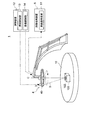
- FIG. 1 is a schematic configuration diagram of a foreign object detection device including a robot arm (a state in which a unidirectional solidified blade is placed vertically).
- FIG. 1 is a schematic configuration diagram of a foreign object detection device including a robot arm (a state in which a unidirectional solidified blade is placed horizontally). It is a flowchart of the heterocrystal inspection method of the unidirectional solidified material which concerns on one Embodiment.
- a unidirectional solidified foreign crystal inspection apparatus (hereinafter referred to as a different crystal inspection apparatus) 1 according to this embodiment is formed on the surface layer of a unidirectional solidified 100. It is an apparatus for detecting an existing different crystal part.
- the unidirectional solidified material 100 is a product obtained by solidifying molten metal in a certain direction under a unidirectional temperature gradient. For example, a product that requires heat resistance such as a gas turbine or an aircraft engine.
- the different crystal part is a region having a partially different crystal orientation in the unidirectional solidified product 100, for example, a recrystallized part.
- the different crystal inspection apparatus 1 irradiates the inspection target region 102 with light, and an imaging unit 2 for imaging the inspection target region 102.
- the image processing apparatus 5 including 51.
- the imaging unit 2 is configured to capture a plurality of image data by capturing an image of the inspection target region 102 in the unidirectional solidified material 100.
- the image data acquired by the imaging unit 2 is sent to the image processing device 5.
- the imaging unit 2 has an imaging direction C along the vertical direction in order to capture an image of the unidirectional solidified material 100 located immediately below.
- the illumination unit 3 is configured to irradiate the inspection target region 102 of the unidirectional solidified material 100 with light.
- the illumination unit 3 may include, for example, an LED irradiator or a halogen irradiator. A specific configuration of the illumination unit 3 will be described later.
- the irradiation direction changing unit 4 is configured to change the irradiation direction D of the illumination unit 3 with respect to the inspection target region 102. Specifically, as illustrated in FIG. 2, the irradiation direction changing unit 4 applies the light irradiation direction D to the second plane N that is orthogonal to the first plane M including the inspection target region 102, the imaging unit 2, and the illumination unit 3.
- the rotation angle ⁇ of the irradiation direction (hereinafter referred to as the projection irradiation direction) D 1 ′ centered on the inspection target region 102 when 1 is projected is changed. For example, when projecting the irradiation direction D 1 of the illumination unit 3 before irradiation direction changed to the second plane N, projection illumination direction D 1 'is obtained.
- the irradiation direction changing unit 4 has an angle (that is, a rotation angle) ⁇ between the projection irradiation direction D 1 ′ before the irradiation direction change and the projection irradiation direction D 2 ′ after the irradiation direction change is 0.
- the irradiation direction D of the illumination unit 3 is changed so that the value exceeds the degree.
- the irradiation direction changing unit 4 in addition to the rotation angle phi, so as to vary the inclination angle ⁇ of the irradiation direction D 1 around the inspection region 102 of the first plane M It may be configured.
- the inclination angle ⁇ may be the angle of the irradiation direction D 1 with respect to the second plane N.
- the image processing apparatus 5 includes a different crystal specifying unit 51 for specifying a different crystal part.
- the different crystal specifying unit 51 is configured to specify a different crystal part in the inspection target region 102 based on a plurality of image data having different rotation angles ⁇ obtained by the imaging unit 2. A specific configuration of the different crystal specifying unit 51 will be described later.
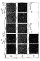
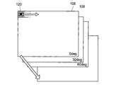
- FIG. 3 shows image data 108 acquired by the inventors' experiment. In this experiment, projection illumination of relative projection illumination direction D 1 'to the second plane N of the irradiation direction D 1 as a reference, as shown in FIG.
- the second plane N of the radiation direction D 2 after irradiation direction change The image data 108 at each rotation angle ⁇ was obtained by increasing the rotation angle ⁇ in the direction D 2 ′ by 30 degrees.
- the position of the recrystallized portion 104 is known in advance before the experiment, and the recrystallized portion 104 is surrounded by a marker line 105.
- the rotation angle ⁇ is 0 ° to 120 °
- the brightness of the surrounding base material portion 103 gradually increases as the rotation angle ⁇ increases.
- the luminance of the crystal part 104 is gradually lowered.
- the rotation angle ⁇ is from 150 degrees to 270 degrees
- the luminance of the surrounding base material portion 103 gradually decreases as the rotation angle ⁇ increases, but the luminance of the recrystallization portion 104 gradually increases. .
- FIG. 4A illustrates a case where the image data of the peripheral portion 103 is acquired by the imaging unit 2 in a state in which the peripheral portion (surrounding base material portion) 103 of the inspection target region 102 is irradiated with light by the illumination unit 3. Shows the state.
- FIG. 4A illustrates a case where the image data of the peripheral portion 103 is acquired by the imaging unit 2 in a state in which the peripheral portion (surrounding base material portion) 103 of the inspection target region 102 is irradiated with light by the illumination unit 3. Shows the state.
- 4B shows a state when image data of the recrystallized portion 104 is acquired by the imaging unit 2 in a state in which the recrystallized portion 104 is irradiated with light from the illumination unit 3 in the inspection target region 102. ing. 4A and 4B, the positional relationship between the imaging unit 2 and the illumination unit 3 with respect to the inspection target region 102 is the same.
- the light irradiated by the illumination unit 3 is reflected by the crystal plane of the inspection target region 102.
- specular reflection with respect to the irradiation direction D of the illumination unit 3
- the amount of light is highest in the regular reflection direction D ′.
- the imaging unit 2 since the imaging unit 2 is not located in the specular reflection direction D ′ reflected by the crystal plane of the surrounding part 103, in this case, the image data acquired by the imaging unit 2 Among them, the luminance of the peripheral portion 103 (peripheral base material portion) becomes low, and the region becomes dark.
- the imaging unit 2 since the imaging unit 2 is located in the mirror reflection direction D ′ reflected by the crystal plane of the recrystallization unit 104, in this case, the image data acquired by the imaging unit 2 Among them, the luminance of the recrystallized portion 104 becomes high and the region becomes bright.
- the luminance is different between the peripheral portion 103 and the recrystallized portion 104. This is presumably because the crystal orientation is different between the surrounding base material portion 103 and the surrounding base material portion 103.
- the irradiation direction changing unit 4 is configured to change the rotation angle ⁇ of the projection irradiation direction D 1 ′ in which the irradiation direction D 1 of the illumination unit 3 is projected, and the different crystal specifying unit 51 is configured. Is a fine different crystal part by being configured to identify the different crystal part in the inspection target region 102 based on a plurality of image data obtained by the imaging unit 2 having different rotation angles ⁇ . Can be detected with high accuracy.
- the different crystal specifying unit 51 associates the difference between the luminance at each position in the inspection target region 102 and the reference luminance indicating the average luminance around the position with the rotation angle ⁇ for each image data. Calculate, and calculate the amplitude of the periodic change of the difference with respect to the rotation angle ⁇ for each position in the inspection target region 102, and specify the position of the different crystal part based on the amplitude of the periodic change.
- FIG. 5 is a graph showing an example of a periodic change in the difference between the recrystallized portion and the reference luminance indicating the average luminance in the peripheral portion (hereinafter simply referred to as a luminance difference between the recrystallized portion and the peripheral portion).
- Lines 111 to 113 are graphs showing the luminance difference between the recrystallized part and the surrounding part with respect to the rotation angle ⁇ in the irradiation direction when the recrystallized part exists. As shown in FIG.
- the rotation angle ⁇ in the irradiation direction is the rotation angle of the projection irradiation direction D 2 ′ after changing the irradiation direction with respect to the reference projection irradiation direction D 1 ′.
- Line 111, the angle of the irradiation direction D 1 with respect to the second plane N theta is represents the luminance difference recrystallization portion and the surrounding portion of the case of 20 degrees, line 112, recrystallization when the angle theta is 40 degrees
- the line 113 represents the luminance difference between the recrystallized part and the peripheral part when the angle ⁇ is 65 degrees.
- a line 110 indicates a periodic change with respect to the rotation angle ⁇ of the difference between the target position of the base material when there is no recrystallized portion and the reference luminance indicating the average luminance of the surrounding portion.
- the amplitude of the line 110 as a comparative example when there is no recrystallized portion is extremely small. That is, when there is no different crystal part in the focus position of the base material and the surrounding portion of the focus position, the crystal orientation of the focus position (base material) and the peripheral portion (base material) is the same, The difference in luminance between the two becomes almost zero.
- the amplitudes A 1 to A 3 of the lines 111 to 113 representing the periodic change of the luminance difference between the recrystallized portion and the surrounding portion with respect to the rotation angle ⁇ are large.
- the crystal orientation between the position of interest (different crystal part) and the surrounding part (base material) is Since they are different, the difference in luminance between the two changes depending on the rotation angle ⁇ . Therefore, the amplitudes A 1 to A 3 increase in the periodic change with respect to the rotation angle ⁇ of the luminance difference between the recrystallized portion and the surrounding portion.
- the above configuration utilizes the above knowledge of the present inventors, and the periodic change of the difference between the luminance at each position in the inspection target region 102 and the reference luminance indicating the average luminance around the position is described. Based on the amplitude, the position of the different crystal part is specified. Thereby, it is possible to detect a fine different crystal part with high accuracy from the amplitude of the periodic change of the difference between the luminance at each position in the inspection target region 102 and the reference luminance indicating the average luminance around the position. Can do.
- the different crystal specifying unit 51 sets a threshold value in advance, and the difference cycle between the luminance at each position in the inspection target region 102 and the reference luminance indicating the average luminance around the position. It may be determined that the different crystal part is present at a position where the amplitude of the target change exceeds the threshold value. In this case, a fine different crystal part can be detected with high accuracy by appropriately setting the threshold value.
- the different crystal specifying unit 51 calculates the luminance at each position in the inspection target region 102 and the reference luminance indicating the average luminance around the position in association with the rotation angle ⁇ for each image data. Then, a peak difference, which is a difference between the peak in the periodic change in luminance with respect to the rotation angle ⁇ and the reference peak in the periodic change in reference luminance with respect to the rotation angle ⁇ , is calculated for each position in the inspection target region 102, and the peak difference is calculated. Based on the above, the position of the different crystal part is specified.
- FIG. 6 is a graph showing an example of a periodic change in luminance with respect to the rotation angle ⁇ in the irradiation direction.
- the rotation angle ⁇ in the irradiation direction is the rotation angle of the projection irradiation direction D 2 ′ after changing the irradiation direction with respect to the reference projection irradiation direction D 1 ′.
- a line 115 represents a periodic change in luminance in the different crystal part
- a line 116 represents a periodic change in luminance in the peripheral part of the different crystal part.
- a fine different crystal part is obtained from a peak difference that is a difference between a luminance peak at each position in the inspection target region 102 and a reference luminance peak indicating an average luminance around the position. It can be detected with high accuracy.
- the different crystal specifying unit 51 may set a threshold value in advance and determine that a different crystal portion exists at a position where the peak difference at each position in the inspection target region 102 exceeds the threshold value. Good. In this case, a fine different crystal part can be detected with high accuracy by appropriately setting the threshold value.
- the different crystal specifying unit 51 associates the luminance at each position in the inspection target region 102 and the reference luminance indicating the average luminance around the position with the rotation angle ⁇ for each image data.
- a phase difference that is a difference between the phase in the periodic change of the luminance with respect to the rotation angle ⁇ and the reference phase in the periodic change of the reference luminance with respect to the rotation angle ⁇ is calculated for each position in the inspection target region 102.
- the position of the different crystal part is specified based on the difference.
- a fine different crystal part is obtained from the phase difference that is the difference between the luminance phase at each position in the inspection target region 102 and the phase of the reference luminance indicating the average luminance around the position. It can be detected with high accuracy.
- the different crystal specifying unit 51 may set a threshold value in advance and determine that a different crystal portion exists at a position where the phase difference at each position in the inspection target region 102 exceeds the threshold value. Good. In this case, a fine different crystal part can be detected with high accuracy by appropriately setting the threshold value.
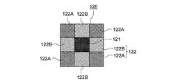
- FIG. 7 is a diagram for explaining a method for measuring luminance in the image data 108.
- the different crystal specifying unit 51 calculates the average luminance of the peripheral portion 122 (including 122A and 122B) in the image data 108, and refers to the average luminance. It may be configured to be used as luminance. For example, in measuring the luminance, first, the image data 108 is scanned using the filter 120 having a predetermined filter size. Then, the brightness of the center area 121 of the filter 120 is measured, and this is used as the brightness of the position of interest in the image data 108. In addition, the luminance of the surrounding region 122 (including 122A and 122B) of the central region 121 is measured, and the average luminance in the surrounding portion is calculated using the measured plurality of luminances.
- the different crystal specifying unit 51 calculates an average luminance for a region including a focused position (focused position) 120 and its peripheral portion (including 122A and 122B) in the image data 108,
- the average luminance may be used as the reference luminance.
- the image data 108 is scanned using the filter 120 having a predetermined filter size.
- the brightness of the center area 121 of the filter 120 is measured, and this is used as the brightness of the position of interest in the image data 108.
- the brightness of the surrounding area 122 (including 122A and 122B) of the center area 121 is measured, and the average brightness in the surrounding area is calculated using the brightness in the center area 122 and the plurality of brightness in the surrounding area 122.
- the luminance of the surrounding region 122 may be measured for at least some of the regions 122A or 122B among the plurality of regions 122A and 122B partitioned in a grid pattern. For example, when the regions 122A and the regions 122B are alternately arranged, the luminance of the surrounding region 122 may be measured for the region 122A or the region 122B. According to these configurations, it is possible to appropriately obtain the reference luminance indicating the average luminance in the periphery of the position of interest.
- the different crystal specifying unit 51 may be configured to perform a low-pass filter process on at least a part of the image data 108 to calculate the reference luminance. According to this configuration, it is possible to appropriately acquire the reference luminance indicating the average luminance in the peripheral portion of the position of interest by simple processing using a low-pass filter.
- FIG. 1 is a perspective view of a different crystal inspection apparatus 1 according to an embodiment.
- the irradiation direction changing unit 4 includes a first annular track portion 41 that forms a track for the illumination unit 3 to rotate.
- the first annular track portion 41 is provided so as to surround the inspection target region 102 of the unidirectional solidified material 100, and the illumination unit 3 rotates around the inspection target region 102 in the second plane N (see FIG. 2).
- the illumination unit 3 is configured to be movable around the inspection target region 102 along the first annular track portion 41 so that the rotation angle ⁇ changes.
- the first annular track portion 41 includes an inner ring 41A and an outer ring 41B configured to be rotatable relative to the inner ring 41A.
- 41 A of inner rings are fixed to the outer peripheral surface of the disk-shaped mounting base 10 in which the unidirectional solidified material 100 is mounted.
- the outer ring 41B is disposed on the outer peripheral side of the inner ring 41A.
- An annular member 42 is attached to the outer peripheral side of the outer ring 41B, and a support column 43 for supporting the illumination unit 3 is fixed to the outer ring 41B via the annular member 42.
- pillar part 43 rotate with the drive mechanism not shown.
- the inner ring 41A, the mounting table 10, and the unidirectional solidified product 100 are in a stationary state.
- the imaging unit 2 is supported by the column unit 21. Since the support column 21 is attached to a stationary part, the imaging unit 2 is kept stationary regardless of the rotation of the illumination unit 3.
- the different crystal inspection apparatus 1 may further include a control device 12 including an illumination control unit 13 and an imaging control unit 14.
- the illumination control unit 13 is configured to control lighting and adjust the rotation of the illumination unit 3 by controlling a driving mechanism (not shown).
- the imaging control unit 14 is configured to control the imaging timing in the imaging unit 2 so as to be synchronized with the rotation of the illumination unit 3 and the lighting of the illumination.
- the rotation angle ⁇ in the irradiation direction (see FIG. 2) can be freely adjusted by moving the illumination unit 3 around the inspection target region 102 along the first annular track portion 41. . Therefore, it is possible to detect the different crystal part with high accuracy.
- FIG. 8 is a perspective view showing a configuration of a different crystal inspection apparatus 1 according to another embodiment.
- the different crystal inspection apparatus 1 includes a plurality of illumination units 3.
- the plurality of illumination units 3 are arranged so as to surround the imaging unit 2, and each illumination unit 3 can be turned on independently of each other.
- the irradiation direction changing unit 4 is configured to change the rotation angle ⁇ (see FIG. 2) in the irradiation direction by switching the lighting unit 3 that is turned on among the plurality of lighting units 3.
- the plurality of illumination units 3 are attached to an annular support unit 44 arranged so as to surround the imaging unit 2.
- the annular support portion 44 may be attached to the column portion 21 for supporting the imaging unit 2.
- a plurality of illumination units 3 are attached to the annular support unit 44 at predetermined intervals.
- the bottom surfaces of the plurality of illumination units 3 may be substantially the same height as the bottom surface of the imaging unit 2.
- the different crystal inspection apparatus 1 may further include a control device 12 including an illumination control unit 13 and an imaging control unit 14.
- the illumination control unit 13 is configured to control lighting.
- the illumination control unit 13 plays the role of the irradiation direction changing unit 4. That is, the illumination control unit 13 switches the illumination unit 3 to be turned on among the plurality of illumination units 3, and the rotation angle ⁇ in the irradiation direction (see FIG. 2) changes.
- the irradiation direction changing unit 4 controls each lighting unit 3 so that the lighting units 3 are sequentially turned on in the direction of arrow E in the drawing.
- the imaging control unit 14 is configured to control the imaging timing in the imaging unit 2 so as to be synchronized with the lighting of the illumination by the illumination control unit 13.
- the rotation angle (phi) of the irradiation direction D (refer FIG. 2) is switched by switching the illumination part 3 lighted among the some illumination parts 3 by the irradiation direction change part 4 (illumination control part 13). Can be adjusted freely. Therefore, it is possible to detect the different crystal part with high accuracy.
- the rotation angle ⁇ in the irradiation direction D can be quickly changed. As a result, the time required to acquire image data for a plurality of rotation angles ⁇ can be reduced, and inspection of different crystal parts can be performed efficiently.
- FIG. 9 is a perspective view showing a configuration of a different crystal inspection apparatus 1 according to a modification of the other embodiment shown in FIG. In this modification, the description of the same configuration as in FIG. 8 is omitted.
- the irradiation direction changing unit 4 includes a second annular track 45 that is provided so as to surround the imaging unit 2 and is fixed to the imaging unit 2. .
- the illumination unit 3 is configured to be movable around the imaging unit 2 along the second annular track unit 45 so that the rotation angle ⁇ (see FIG. 2) in the irradiation direction D changes.
- the rotation angle ⁇ in the irradiation direction D can be freely adjusted by moving the illumination unit 3 around the imaging unit 2 along the second annular track unit 45. Therefore, it is possible to detect the different crystal part with high accuracy.
- FIG. 10 is a perspective view showing a configuration of a different crystal inspection apparatus 1 according to still another embodiment.
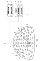
- the different crystal inspection device 1 further includes a dome illumination device 15 in which a plurality of illumination units 3 are arranged along a hemispherical surface.
- Each illumination unit 3 of the dome illumination device 15 is configured to be lit independently of each other.
- Each illumination unit 3 may be a small spot illumination, for example.
- the irradiation direction changing unit 4 is configured to change the rotation angle ⁇ by switching the illuminating unit 3 that is turned on among the plurality of illuminating units 3 arranged along the hemispherical surface.
- the hemispherical surface not only represents a hemispherical surface in a strict sense, but also includes a surface having a generally hemispherical shape.
- the different crystal inspection apparatus 1 may further include a control device 12 including an illumination control unit 13 and an imaging control unit 14.
- the illumination control unit 13 is configured to control lighting of each illumination unit 3.
- the illumination control unit 13 plays the role of the irradiation direction changing unit 4. That is, the illumination control unit 13 switches the illumination unit 3 to be turned on among the plurality of illumination units 3, and the rotation angle ⁇ in the irradiation direction (see FIG. 2) changes.
- the imaging control unit 14 is configured to control the imaging timing in the imaging unit 2 so as to be synchronized with the lighting of the illumination by the illumination control unit 13.
- the rotation angle (phi) of an irradiation direction can be adjusted freely by switching the illumination part 3 lighted among the some illumination parts 3 by the irradiation direction change part 4 (illumination control part 13). it can. Therefore, it is possible to detect the different crystal part with high accuracy.
- the lighting unit 3 that is turned on is switched instead of moving the lighting unit 3, the rotation angle ⁇ in the irradiation direction (see FIG. 2) can be quickly changed. As a result, the time required to acquire image data for a plurality of rotation angles ⁇ can be reduced, and inspection of different crystal parts can be performed efficiently.
- the dome illumination device 15 more illumination units 3 can be provided.
- an illumination unit row formed by a plurality of illumination units 3 arranged along a circumferential line intersecting with the hemispherical second plane N (see FIG. 2) of the dome illumination device 15 is represented by the second plane N.
- a plurality of rows can be provided along the direction perpendicular to the. In this case, it is possible to freely adjust not only the rotation angle ⁇ but also the inclination angle ⁇ (see FIG. 2) of the light irradiation direction by switching the illumination unit 3 to be lit among the plurality of illumination units 3. Become.
- the imaging unit 2 is configured to be movable in the first plane M or the second plane N. Depending on the crystal orientation of the different crystal part, the positional relationship between the imaging unit 2 and the inspection target region 102 suitable for detecting the different crystal part can be changed. In this regard, according to the above configuration, since the imaging unit 2 can move in the first plane M or the second plane N, the inspection of the different crystal part is performed while changing the positional relationship between the imaging unit 2 and the inspection target region 102. It can be performed. Therefore, the robustness of the inspection of the different crystal part is improved.
- the irradiation direction changing unit 4 in addition to the rotation angle phi, is constituted tilt angle of the irradiation direction D 1 that the inspection region 102 of the first plane M as the center ⁇ to change (see FIG. 2) May be.
- the inclination angle theta the angle of the irradiation direction D 1 with respect to the second plane N.
- the different crystal specifying unit 51 is configured to specify the different crystal part based on a plurality of pieces of image data having different inclination angles ⁇ and rotation angles ⁇ obtained by the imaging unit 2.
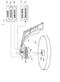
- the different crystal inspection apparatus 1 may further include a robot arm 17 to which the illumination unit 3 and the imaging unit 2 are attached.
- 11A and 11B are schematic configuration diagrams of the different crystal inspection apparatus 1 including the robot arm 17, and FIG. 11A is a different crystal inspection in a case where the unidirectional solidified blade 100 to be inspected is vertically placed. The state of the apparatus 1 is shown, and FIG. 11B shows the state of the different crystal inspection apparatus 1 when the unidirectional solidified blade 100 is placed horizontally.
- a unidirectional solidified blade (turbine cast blade) is shown as the unidirectional solidified product 100.
- the unidirectional solidified blade 100 is placed on a pedestal 61 installed on a swivel base 60.
- FIG. 11A the unidirectional solidified blade 100 is placed on the gantry 61 in a vertically placed state
- FIG. 11B the unidirectional solidified blade is placed on the pedestal 61 in a horizontally placed state.
- the posture of the unidirectional solidified blade 100 is appropriately set according to the inspection target region 102.
- a mechanism including the illumination unit 3 and the imaging unit 2 as shown in FIGS. 1 and 8 to 10 is attached to the tip of the robot arm 17.
- the robot arm 17 has a plurality of joints, and the postures of the imaging unit 2 and the illumination unit 3 can be adjusted. According to this configuration, it is possible to efficiently inspect different crystal parts at various locations in the unidirectional solidified product (unidirectional solidified blade) 100 by operating the robot arm 17.
- the unidirectional solidified foreign crystal inspection method includes an etching process S1, a light irradiation step S2, an imaging step S3, an irradiation direction changing step S4, and different crystal specifying steps S5 to S8. .
- etching process S1 an etching process is performed on the surface of the unidirectional solidified material. Since the surface layer of the unidirectional solidified material is normally in an amorphous state, the surface layer is removed by etching to expose the crystal part.
- Light irradiation step S2 irradiates light with respect to a test object area
- an inspection target region is imaged in the unidirectional solidified product.
- the irradiation direction changing step S4 is a rotation angle of the irradiation direction centered on the inspection target region when the irradiation direction of light is projected onto a second plane orthogonal to the first plane including the inspection target region, the illumination unit, and the imaging unit. Change ⁇ .
- a different crystal portion in the inspection target region is specified based on a plurality of image data having different rotation angles ⁇ obtained in the imaging step S3.
- the different crystal part in the inspection target region is specified based on a plurality of image data having different rotation angles ⁇ obtained in the imaging step. It can be detected with high accuracy.
- the difference between the luminance at each position in the inspection target region and the reference luminance indicating the average luminance around the position (hereinafter referred to as luminance difference) is an image.
- luminance difference is calculated in association with the rotation angle ⁇ , and the amplitude of the periodic change of the difference with respect to the rotation angle ⁇ is calculated for each position in the inspection target area (step S5).
- the luminance difference amplitude is compared with a threshold value (step S6). If the luminance difference amplitude exceeds the threshold value, the position of the different crystal portion is specified (step S7).
- step S8 if the amplitude of the luminance difference is equal to or smaller than the threshold value, it is determined that there is no different crystal part (step S8). According to this method, a fine different crystal part is detected with high accuracy from the amplitude of the periodic change in the difference between the luminance at each position in the inspection target region and the reference luminance indicating the average luminance around the position. can do.
- the luminance at each position in the inspection target region and the reference luminance indicating the average luminance around the position are associated with the rotation angle ⁇ for each image data.
- the peak difference which is the difference between the peak in the periodic change in luminance with respect to the rotation angle ⁇ and the reference peak in the periodic change in reference luminance with respect to the rotation angle ⁇ , is calculated for each position in the inspection target region.
- the position of the different crystal part may be specified based on the difference. According to this method, a fine different crystal part is accurately obtained from a peak difference that is a difference between a luminance peak at each position in the inspection target region and a reference luminance peak indicating an average luminance around the position. Can be detected.
- the luminance at each position in the inspection target region and the reference luminance indicating the average luminance around the position are set as the rotation angle ⁇ for each image data.
- Calculating the phase difference which is the difference between the phase in the periodic change of the luminance with respect to the rotation angle ⁇ and the reference phase in the periodic change of the reference luminance with respect to the rotation angle ⁇ , for each position in the inspection target region;
- the position of the different crystal part may be specified based on the phase difference. According to this method, a fine different crystal part is accurately obtained from a phase difference that is a difference between a luminance phase at each position in the inspection target area and a reference luminance phase indicating an average luminance around the position. Can be detected.
- the unidirectional solidified product may be a gas turbine or a turbine casting blade of an aircraft engine.
- a turbine casting blade of a gas turbine or an aircraft engine casting distortion due to mold restraint may occur during solidification cooling after casting, and a recrystallized portion may occur.
- the recrystallized portion is a different crystal portion having a crystal orientation different from that of the base material. For this reason, the recrystallization part of the turbine casting blade of a gas turbine or an aircraft engine can be detected with high accuracy by the method described above.
- the present invention by specifying different crystal parts in the inspection target region based on a plurality of image data obtained by the imaging unit and having different rotation angles ⁇ . Even a fine different crystal part can be detected with high accuracy.
- the present invention is not limited to the above-described embodiments, and includes forms obtained by modifying the above-described embodiments and forms obtained by appropriately combining these forms.
- expressions representing shapes such as quadrangular shapes and cylindrical shapes represent not only geometrically strict shapes such as quadrangular shapes and cylindrical shapes, but also irregularities and chamfers as long as the same effects can be obtained.
- a shape including a part or the like is also expressed.
- the expression “comprising”, “including”, or “having” one constituent element is not an exclusive expression that excludes the presence of the other constituent elements.
Landscapes
- Physics & Mathematics (AREA)
- Health & Medical Sciences (AREA)
- Life Sciences & Earth Sciences (AREA)
- Chemical & Material Sciences (AREA)
- Analytical Chemistry (AREA)
- Biochemistry (AREA)
- General Health & Medical Sciences (AREA)
- General Physics & Mathematics (AREA)
- Immunology (AREA)
- Pathology (AREA)
- Investigating Materials By The Use Of Optical Means Adapted For Particular Applications (AREA)
- Investigating Or Analysing Materials By Optical Means (AREA)
Abstract
一方向性凝固物の異結晶検査装置は、前記一方向性凝固物のうち検査対象領域に対して光を照射するための照明部と、前記検査対象領域を撮像するための撮像部と、前記検査対象領域、前記照明部および前記撮像部を含む第1平面に直交する第2平面に前記光の照射方向を投影したときにおける、前記検査対象領域を中心とした前記照射方向の回転角度φを変化させるように構成された照射方向変更部と、前記撮像部によって得られた前記回転角度φが異なる複数の画像データに基づいて、前記検査対象領域内における異結晶部を特定するための異結晶特定部と、を備える。
Description
本開示は、一方向性凝固物における異結晶部を検出するための一方向性凝固物の異結晶検査装置及び検査方法に関する。
従来から、効率向上の観点から、ガスタービンや航空機エンジンでは燃焼ガスの高温化が進んでいる。これに伴い、高温に耐え得るタービン翼の材料として、一方向性凝固鋳造物が知られている。
一方向性凝固鋳造物は、鋳造後の凝固冷却時に鋳型の拘束に起因した鋳造ひずみが発生し、再結晶部(異結晶部)が発生することがある。一方向性凝固鋳造物における再結晶部は、強度が小さく、亀裂発生の要因となるため、タービン翼の疲労強度低下を招く可能性がある。
そこで、一方向性凝固物における異結晶部を検出可能な検査方法の提案が望まれる。
そこで、一方向性凝固物における異結晶部を検出可能な検査方法の提案が望まれる。
特許文献1には、結晶方位に応じた超音波の伝播速度差を利用し、単結晶材料の異結晶域を検出する方法が開示されている。具体的には、単結晶材料からなる被検査体の表面から超音波を入射し、裏面からの反射波を検出する。そして、2箇所以上において、超音波入射から裏面反射波の検出までの時間を計測する。こうして得られた2箇所以上における前記時間の差に基づいて、異結晶域の存在を検知するようになっている。
しかしながら、特許文献1に記載の方法では、ある程度大きな異結晶域の存在を検出することはできるかもしれないが、微細な異結晶部の検出は難しい。
本発明の少なくとも幾つかの実施形態の目的は、微細な異結晶部の検出が可能な一方向性凝固物の異結晶検査装置及び検査方法を提供する点にある。
(1)本発明の少なくとも幾つかの実施形態に係る一方向性凝固物の異結晶検査装置は、
前記一方向性凝固物のうち検査対象領域に対して光を照射するための照明部と、
前記検査対象領域を撮像するための撮像部と、
前記検査対象領域、前記照明部および前記撮像部を含む第1平面に直交する第2平面に前記光の照射方向を投影したときにおける、前記検査対象領域を中心とした前記照射方向の回転角度φを変化させるように構成された照射方向変更部と、
前記撮像部によって得られた前記回転角度φが異なる複数の画像データに基づいて、前記検査対象領域内における異結晶部を特定するための異結晶特定部と、を備える。
前記一方向性凝固物のうち検査対象領域に対して光を照射するための照明部と、
前記検査対象領域を撮像するための撮像部と、
前記検査対象領域、前記照明部および前記撮像部を含む第1平面に直交する第2平面に前記光の照射方向を投影したときにおける、前記検査対象領域を中心とした前記照射方向の回転角度φを変化させるように構成された照射方向変更部と、
前記撮像部によって得られた前記回転角度φが異なる複数の画像データに基づいて、前記検査対象領域内における異結晶部を特定するための異結晶特定部と、を備える。
本発明者らが鋭意検討した結果、検査対象領域を中心とした照射方向の回転角度φが異なる条件で撮像した画像データを比較すると、再結晶部とその周囲母材部とで回転角度φに対する輝度の変化の仕方が異なることを見出した。これは、再結晶部とその周囲母材部とで、結晶方位が異なるためだと考えられる。
上記(1)の構成は、本発明者らの上記知見を利用したものであり、撮像部によって得られた回転角度φが異なる複数の画像データに基づいて、検査対象領域内における異結晶部を特定するようになっている。これにより、微細な異結晶部であっても高精度に検出することができる。
上記(1)の構成は、本発明者らの上記知見を利用したものであり、撮像部によって得られた回転角度φが異なる複数の画像データに基づいて、検査対象領域内における異結晶部を特定するようになっている。これにより、微細な異結晶部であっても高精度に検出することができる。
(2)幾つかの実施形態では、上記(1)の構成において、
前記異結晶特定部は、
前記検査対象領域内の各位置における輝度と、当該位置の周囲部の平均輝度を示す参照輝度との差分を前記画像データごとに前記回転角度φと関連付けて算出し、
前記回転角度φに対する前記差分の周期的変化の振幅を前記検査対象領域内の各位置について算出し、
前記周期的変化の振幅に基づいて、前記異結晶部の位置を特定する
ように構成される。
前記異結晶特定部は、
前記検査対象領域内の各位置における輝度と、当該位置の周囲部の平均輝度を示す参照輝度との差分を前記画像データごとに前記回転角度φと関連付けて算出し、
前記回転角度φに対する前記差分の周期的変化の振幅を前記検査対象領域内の各位置について算出し、
前記周期的変化の振幅に基づいて、前記異結晶部の位置を特定する
ように構成される。
本発明者らの鋭意検討の結果、異結晶部の結晶方位は母材の結晶方位とは異なるため、異結晶部と母材との輝度の差分は回転角度φに応じて変化することが明らかになった。
上記(2)の構成は、本発明者らの上記知見を利用したものであり、検査対象領域内の各位置における輝度と、当該位置の周囲部の平均輝度を示す参照輝度との差分の周期的変化の振幅に基づき、異結晶部の位置を特定するものである。
着目する位置に異結晶部が存在し、且つ、当該位置の周囲部には異結晶部が存在しない場合、着目位置(異結晶部)とその周囲部(母材)との結晶方位が異なるため、両者の輝度の差分は回転角度φに応じて変化する。一方、着目する位置および当該位置の周囲部の何れにも異結晶部が存在しない場合、着目位置(母材)とその周囲部(母材)との結晶方位が同一であるため、両者の輝度の差分はほぼゼロになる。
よって、上記(2)の構成のように、検査対象領域内の各位置における輝度と、当該位置の周囲部の平均輝度を示す参照輝度との差分の周期的変化の振幅から、微細な異結晶部を高精度に検出することができる。
上記(2)の構成は、本発明者らの上記知見を利用したものであり、検査対象領域内の各位置における輝度と、当該位置の周囲部の平均輝度を示す参照輝度との差分の周期的変化の振幅に基づき、異結晶部の位置を特定するものである。
着目する位置に異結晶部が存在し、且つ、当該位置の周囲部には異結晶部が存在しない場合、着目位置(異結晶部)とその周囲部(母材)との結晶方位が異なるため、両者の輝度の差分は回転角度φに応じて変化する。一方、着目する位置および当該位置の周囲部の何れにも異結晶部が存在しない場合、着目位置(母材)とその周囲部(母材)との結晶方位が同一であるため、両者の輝度の差分はほぼゼロになる。
よって、上記(2)の構成のように、検査対象領域内の各位置における輝度と、当該位置の周囲部の平均輝度を示す参照輝度との差分の周期的変化の振幅から、微細な異結晶部を高精度に検出することができる。
(3)幾つかの実施形態では、上記(1)の構成において、
前記異結晶特定部は、
前記検査対象領域内の各位置における輝度、および、当該位置の周囲部の平均輝度を示す参照輝度を前記画像データごとに前記回転角度φと関連付けて算出し、
前記回転角度φに対する前記輝度の周期的変化におけるピークと、前記回転角度φに対する前記参照輝度の周期的変化における参照ピークとの差であるピーク差分を前記検査対象領域内の各位置について算出し、
前記ピーク差分に基づいて、前記異結晶部の位置を特定する
ように構成される。
前記異結晶特定部は、
前記検査対象領域内の各位置における輝度、および、当該位置の周囲部の平均輝度を示す参照輝度を前記画像データごとに前記回転角度φと関連付けて算出し、
前記回転角度φに対する前記輝度の周期的変化におけるピークと、前記回転角度φに対する前記参照輝度の周期的変化における参照ピークとの差であるピーク差分を前記検査対象領域内の各位置について算出し、
前記ピーク差分に基づいて、前記異結晶部の位置を特定する
ように構成される。
本発明者らの鋭意検討の結果、異結晶部の結晶方位は母材の結晶方位とは異なるため、異結晶部の輝度ピークと母材の輝度ピークとは相違することが明らかになった。
上記(3)の構成は、本発明者らの上記知見を利用したものであり、検査対象領域内の各位置における輝度のピークと、当該位置の周囲部の平均輝度を示す参照輝度のピークとの差であるピーク差分に基づき、異結晶部の位置を特定するものである。
着目する位置に異結晶部が存在し、且つ、当該位置の周囲部には異結晶部が存在しない場合、着目位置(異結晶部)とその周囲部(母材)との結晶方位が異なるため、両者の輝度ピークは相違する。一方、着目する位置および当該位置の周囲部の何れにも異結晶部が存在しない場合、着目位置(母材)とその周囲部(母材)との結晶方位が同一であるため、両者の輝度ピークはほぼ同等の大きさである。
よって、上記(3)の構成のように、検査対象領域内の各位置における輝度ピークと、当該位置の周囲部の平均輝度を示す参照輝度のピークとの差であるピーク差分から、微細な異結晶部を高精度に検出することができる。
上記(3)の構成は、本発明者らの上記知見を利用したものであり、検査対象領域内の各位置における輝度のピークと、当該位置の周囲部の平均輝度を示す参照輝度のピークとの差であるピーク差分に基づき、異結晶部の位置を特定するものである。
着目する位置に異結晶部が存在し、且つ、当該位置の周囲部には異結晶部が存在しない場合、着目位置(異結晶部)とその周囲部(母材)との結晶方位が異なるため、両者の輝度ピークは相違する。一方、着目する位置および当該位置の周囲部の何れにも異結晶部が存在しない場合、着目位置(母材)とその周囲部(母材)との結晶方位が同一であるため、両者の輝度ピークはほぼ同等の大きさである。
よって、上記(3)の構成のように、検査対象領域内の各位置における輝度ピークと、当該位置の周囲部の平均輝度を示す参照輝度のピークとの差であるピーク差分から、微細な異結晶部を高精度に検出することができる。
(4)幾つかの実施形態では、上記(1)の構成において、
前記異結晶特定部は、
前記検査対象領域内の各位置における輝度、および、当該位置の周囲部の平均輝度を示す参照輝度を前記画像データごとに前記回転角度φと関連付けて算出し、
前記回転角度φに対する前記輝度の周期的変化における位相と、前記回転角度φに対する前記参照輝度の周期的変化における参照位相との差である位相差分を前記検査対象領域内の各位置について算出し、
前記位相差分に基づいて、前記異結晶部の位置を特定する
ように構成される。
前記異結晶特定部は、
前記検査対象領域内の各位置における輝度、および、当該位置の周囲部の平均輝度を示す参照輝度を前記画像データごとに前記回転角度φと関連付けて算出し、
前記回転角度φに対する前記輝度の周期的変化における位相と、前記回転角度φに対する前記参照輝度の周期的変化における参照位相との差である位相差分を前記検査対象領域内の各位置について算出し、
前記位相差分に基づいて、前記異結晶部の位置を特定する
ように構成される。
本発明者らの鋭意検討の結果、異結晶部の結晶方位は母材の結晶方位とは異なるため、異結晶部の輝度位相と母材の輝度位相とは相違することが明らかになった。
上記(4)の構成は、本発明者らの上記知見を利用したものであり、検査対象領域内の各位置における輝度の位相と、当該位置の周囲部の平均輝度を示す参照輝度の位相との差である位相差分に基づき、異結晶部の位置を特定するものである。
着目する位置に異結晶部が存在し、且つ、当該位置の周囲部には異結晶部が存在しない場合、着目位置(異結晶部)とその周囲部(母材)との結晶方位が異なるため、両者の輝度位相は相違する。一方、着目する位置および当該位置の周囲部の何れにも異結晶部が存在しない場合、着目位置(母材)とその周囲部(母材)との結晶方位が同一であるため、両者の輝度位相はほぼ一致する。
よって、上記(4)の構成のように、検査対象領域内の各位置における輝度位相と、当該位置の周囲部の平均輝度を示す参照輝度の位相との差である位相差分から、微細な異結晶部を高精度に検出することができる。
上記(4)の構成は、本発明者らの上記知見を利用したものであり、検査対象領域内の各位置における輝度の位相と、当該位置の周囲部の平均輝度を示す参照輝度の位相との差である位相差分に基づき、異結晶部の位置を特定するものである。
着目する位置に異結晶部が存在し、且つ、当該位置の周囲部には異結晶部が存在しない場合、着目位置(異結晶部)とその周囲部(母材)との結晶方位が異なるため、両者の輝度位相は相違する。一方、着目する位置および当該位置の周囲部の何れにも異結晶部が存在しない場合、着目位置(母材)とその周囲部(母材)との結晶方位が同一であるため、両者の輝度位相はほぼ一致する。
よって、上記(4)の構成のように、検査対象領域内の各位置における輝度位相と、当該位置の周囲部の平均輝度を示す参照輝度の位相との差である位相差分から、微細な異結晶部を高精度に検出することができる。
(5)幾つかの実施形態では、上記(2)乃至(4)の何れかの構成において、
前記異結晶特定部は、
前記振幅、前記ピーク差分または前記位相差分が閾値を超えた位置において前記異結晶部が存在すると判定する
ように構成される。
前記異結晶特定部は、
前記振幅、前記ピーク差分または前記位相差分が閾値を超えた位置において前記異結晶部が存在すると判定する
ように構成される。
上記(5)の構成によれば、閾値を適切に設定することにより、微細な異結晶部を高精度に検出することができる。
(6)幾つかの実施形態では、上記(2)乃至(5)の何れかの構成において、
前記異結晶特定部は、
前記画像データのうち前記周囲部について平均輝度を算出し、該平均輝度を前記参照輝度として用いる
ように構成される。
(7)他の幾つかの実施形態では、上記(2)乃至(5)の何れかの構成において、
前記異結晶特定部は、
前記画像データのうち前記位置および前記周囲部からなる領域について平均輝度を算出し、該平均輝度を前記参照輝度として用いる
ように構成される。
前記異結晶特定部は、
前記画像データのうち前記周囲部について平均輝度を算出し、該平均輝度を前記参照輝度として用いる
ように構成される。
(7)他の幾つかの実施形態では、上記(2)乃至(5)の何れかの構成において、
前記異結晶特定部は、
前記画像データのうち前記位置および前記周囲部からなる領域について平均輝度を算出し、該平均輝度を前記参照輝度として用いる
ように構成される。
上記(6)又は(7)の構成により、着目する位置の周囲部における平均輝度を示す参照輝度を適切に得ることができ、上記(2)~(5)の構成による異結晶部の高精度な検出が可能になる。
(8)幾つかの実施形態では、上記(2)乃至(7)の何れかの構成において、
前記異結晶特定部は、
前記画像データにおける少なくとも一部の領域についてローパスフィルタ処理を施して、前記参照輝度を算出する
ように構成される。
前記異結晶特定部は、
前記画像データにおける少なくとも一部の領域についてローパスフィルタ処理を施して、前記参照輝度を算出する
ように構成される。
上記(8)の構成によれば、ローパスフィルタを用いた簡素な処理にて、着目位置の周囲部における平均輝度を示す参照輝度を適切に取得することができる。これにより、上記(2)~(7)の構成による異結晶部の高精度な検出が可能になる。
(9)幾つかの実施形態では、上記(1)乃至(8)の何れかの構成において、
前記照射方向変更部は、
前記一方向性凝固物の前記検査対象領域を取り囲むように設けられ、前記第2平面内において前記検査対象領域の周りにて前記照明部が回動するための軌道を形成する第1環状軌道部
を含み、
前記照明部は、前記回転角度φが変化するように前記第1環状軌道部に沿って前記検査対象領域の周りを移動可能に構成される。
前記照射方向変更部は、
前記一方向性凝固物の前記検査対象領域を取り囲むように設けられ、前記第2平面内において前記検査対象領域の周りにて前記照明部が回動するための軌道を形成する第1環状軌道部
を含み、
前記照明部は、前記回転角度φが変化するように前記第1環状軌道部に沿って前記検査対象領域の周りを移動可能に構成される。
上記(9)の構成によれば、第1環状軌道部に沿って照明部を検査対象領域の周りにおいて移動させることで、照射方向の回転角度φを自由に調節することができる。よって、上記(1)~(8)の構成による異結晶部の高精度な検出が可能になる。
(10)他の幾つかの実施形態では、上記(1)乃至(8)の何れかの構成において、
複数の前記照明部が、前記撮像部を取り囲むように配列されており、且つ、各々の前記照明部が互いに独立して点灯可能であり、
前記照射方向変更部は、
複数の前記照明部のうち点灯される照明部を切り替えることで、前記回転角度φを変化させる
ように構成される。
複数の前記照明部が、前記撮像部を取り囲むように配列されており、且つ、各々の前記照明部が互いに独立して点灯可能であり、
前記照射方向変更部は、
複数の前記照明部のうち点灯される照明部を切り替えることで、前記回転角度φを変化させる
ように構成される。
上記(10)の構成によれば、照射方向変更部によって、複数の照明部のうち点灯される照明部を切り替えることで、照射方向の回転角度φを自由に調節することができる。よって、上記(1)~(8)の構成による異結晶部の高精度な検出が可能になる。
また、照明部を移動させるのではなく、点灯する照明部を切り替えるようにしたので、照射方向の回転角度φの変更を迅速に行うことができる。これにより、複数の回転角度φについての画像データを取得するのに必要な時間を削減し、異結晶部の検査を効率的に行うことができる。
また、照明部を移動させるのではなく、点灯する照明部を切り替えるようにしたので、照射方向の回転角度φの変更を迅速に行うことができる。これにより、複数の回転角度φについての画像データを取得するのに必要な時間を削減し、異結晶部の検査を効率的に行うことができる。
(11)他の幾つかの実施形態では、上記(1)乃至(8)の何れかの構成において、
前記照射方向変更部は、
前記撮像部を取り囲むように設けられ、前記撮像部に対して固定された第2環状軌道部
を含み、
前記照明部は、前記回転角度φが変化するように前記第2環状軌道部に沿って前記撮像部の周りを移動可能に構成される。
前記照射方向変更部は、
前記撮像部を取り囲むように設けられ、前記撮像部に対して固定された第2環状軌道部
を含み、
前記照明部は、前記回転角度φが変化するように前記第2環状軌道部に沿って前記撮像部の周りを移動可能に構成される。
上記(11)の構成によれば、第2環状軌道部に沿って照明部を撮像部の周りにおいて移動させることで、照射方向の回転角度φを自由に調節することができる。よって、上記(1)~(8)の構成による異結晶部の高精度な検出が可能になる。
(12)他の幾つかの実施形態では、上記(1)乃至(8)の何れかの構成において、
前記異結晶検査装置は、複数の前記照明部が半球面に沿って配置されたドーム照明装置をさらに備え、
前記ドーム照明装置の各々の前記照明部は、互いに独立して点灯可能であり、
前記照射方向変更部は、
前記半球面に沿って配置された複数の前記照明部のうち点灯される照明部を切り替えることで、前記回転角度φを変化させる
ように構成される。
前記異結晶検査装置は、複数の前記照明部が半球面に沿って配置されたドーム照明装置をさらに備え、
前記ドーム照明装置の各々の前記照明部は、互いに独立して点灯可能であり、
前記照射方向変更部は、
前記半球面に沿って配置された複数の前記照明部のうち点灯される照明部を切り替えることで、前記回転角度φを変化させる
ように構成される。
上記(12)の構成によれば、照射方向変更部によって、複数の照明部のうち点灯される照明部を切り替えることで、照射方向の回転角度φを自由に調節することができる。よって、上記(1)~(8)の構成による異結晶部の高精度な検出が可能になる。
また、照明部を移動させるのではなく、点灯する照明部を切り替えるようにしたので、照射方向の回転角度φの変更を迅速に行うことができる。これにより、複数の回転角度φについての画像データを取得するのに必要な時間を削減し、異結晶部の検査を効率的に行うことができる。
さらに、ドーム照明装置を用いることで、より多くの照明部を設けることができる。例えば、ドーム照明装置の半球面の第2平面と交わる円周状の線に沿って配列される複数の照明部によって形成される照明部列を、第2平面に対する垂線方向に沿って複数列設けることができる。この場合、後述する(15)の構成のように、複数の照明部のうち点灯される照明部を切り替えることで、回転角度φだけでなく、光の照射方向の傾き角度θも自由に調節することが可能になる。
また、照明部を移動させるのではなく、点灯する照明部を切り替えるようにしたので、照射方向の回転角度φの変更を迅速に行うことができる。これにより、複数の回転角度φについての画像データを取得するのに必要な時間を削減し、異結晶部の検査を効率的に行うことができる。
さらに、ドーム照明装置を用いることで、より多くの照明部を設けることができる。例えば、ドーム照明装置の半球面の第2平面と交わる円周状の線に沿って配列される複数の照明部によって形成される照明部列を、第2平面に対する垂線方向に沿って複数列設けることができる。この場合、後述する(15)の構成のように、複数の照明部のうち点灯される照明部を切り替えることで、回転角度φだけでなく、光の照射方向の傾き角度θも自由に調節することが可能になる。
(13)幾つかの実施形態では、上記(1)乃至(12)の何れかの構成において、
前記撮像部は、前記第1平面または前記第2平面内において移動可能に構成される。
前記撮像部は、前記第1平面または前記第2平面内において移動可能に構成される。
異結晶部の結晶方位によって、異結晶部の検出のために適切な撮像部と検査対象領域との位置関係は変わり得る。
この点、上記(13)の構成によれば、第1平面または第2平面内において撮像部が移動可能であるため、撮像部と検査対象領域との位置関係を変えながら異結晶部の検査を行うことができる。よって、異結晶部の検査のロバスト性が向上する。
この点、上記(13)の構成によれば、第1平面または第2平面内において撮像部が移動可能であるため、撮像部と検査対象領域との位置関係を変えながら異結晶部の検査を行うことができる。よって、異結晶部の検査のロバスト性が向上する。
(14)幾つかの実施形態では、上記(1)乃至(13)の構成において、
前記異結晶検査装置は、前記照明部および前記撮像部が取り付けられたロボットアームをさらに備える。
前記異結晶検査装置は、前記照明部および前記撮像部が取り付けられたロボットアームをさらに備える。
上記(14)の構成によれば、ロボットアームの操作により、一方向性凝固物における様々な箇所において異結晶部の検査を効率的に行うことが可能である。
(15)幾つかの実施形態では、上記(1)乃至(14)の何れかの構成において、
前記照射方向変更部は、前記回転角度φに加えて、前記第1平面内における前記検査対象領域を中心とした前記照射方向の傾き角度θを変化させるように構成され、
前記異結晶特定部は、前記撮像部によって得られた前記傾き角度θ及び前記回転角度φが異なる複数の画像データに基づいて前記異結晶部を特定するように構成される。
前記照射方向変更部は、前記回転角度φに加えて、前記第1平面内における前記検査対象領域を中心とした前記照射方向の傾き角度θを変化させるように構成され、
前記異結晶特定部は、前記撮像部によって得られた前記傾き角度θ及び前記回転角度φが異なる複数の画像データに基づいて前記異結晶部を特定するように構成される。
(16)本発明の少なくとも幾つかの実施形態に係る一方向性凝固物の異結晶検査方法は、
前記一方向性凝固物の表面に対してエッチング処理を施すエッチングステップと、
前記一方向性凝固物のうち検査対象領域に対して光を照射する光照射ステップと、
前記検査対象領域を撮像する撮像ステップと、
前記検査対象領域、前記照明部および前記撮像部を含む第1平面に直交する第2平面に前記光の照射方向を投影したときにおける、前記検査対象領域を中心とした前記照射方向の回転角度φを変化させる照射方向変更ステップと、
前記撮像ステップによって得られた前記回転角度φが異なる複数の画像データに基づいて、前記検査対象領域内における異結晶部を特定するための異結晶特定ステップと、を備える。
前記一方向性凝固物の表面に対してエッチング処理を施すエッチングステップと、
前記一方向性凝固物のうち検査対象領域に対して光を照射する光照射ステップと、
前記検査対象領域を撮像する撮像ステップと、
前記検査対象領域、前記照明部および前記撮像部を含む第1平面に直交する第2平面に前記光の照射方向を投影したときにおける、前記検査対象領域を中心とした前記照射方向の回転角度φを変化させる照射方向変更ステップと、
前記撮像ステップによって得られた前記回転角度φが異なる複数の画像データに基づいて、前記検査対象領域内における異結晶部を特定するための異結晶特定ステップと、を備える。
上記(16)の方法は、撮像ステップによって得られた回転角度φが異なる複数の画像データに基づいて、検査対象領域内における異結晶部を特定するようになっている。これにより、微細な異結晶部であっても高精度に検出することができる。
(17)幾つかの実施形態では、上記(16)の方法において、
前記異結晶特定ステップでは、
前記検査対象領域内の各位置における輝度と、当該位置の周囲部の平均輝度を示す参照輝度との差分を前記画像データごとに前記回転角度φと関連付けて算出し、
前記回転角度φに対する前記差分の周期的変化の振幅を前記検査対象領域内の各位置について算出し、
前記周期的変化の振幅に基づいて、前記異結晶部の位置を特定する。
前記異結晶特定ステップでは、
前記検査対象領域内の各位置における輝度と、当該位置の周囲部の平均輝度を示す参照輝度との差分を前記画像データごとに前記回転角度φと関連付けて算出し、
前記回転角度φに対する前記差分の周期的変化の振幅を前記検査対象領域内の各位置について算出し、
前記周期的変化の振幅に基づいて、前記異結晶部の位置を特定する。
上記(17)の方法によれば、検査対象領域内の各位置における輝度と、当該位置の周囲部の平均輝度を示す参照輝度との差分の周期的変化の振幅から、微細な異結晶部を高精度に検出することができる。
(18)幾つかの実施形態では、上記(16)の方法において、
前記異結晶特定ステップでは、
前記検査対象領域内の各位置における輝度、および、当該位置の周囲部の平均輝度を示す参照輝度を前記画像データごとに前記回転角度φと関連付けて算出し、
前記回転角度φに対する前記輝度の周期的変化におけるピークと、前記回転角度φに対する前記参照輝度の周期的変化における参照ピークとの差であるピーク差分を前記検査対象領域内の各位置について算出し、
前記ピーク差分に基づいて、前記異結晶部の位置を特定する。
前記異結晶特定ステップでは、
前記検査対象領域内の各位置における輝度、および、当該位置の周囲部の平均輝度を示す参照輝度を前記画像データごとに前記回転角度φと関連付けて算出し、
前記回転角度φに対する前記輝度の周期的変化におけるピークと、前記回転角度φに対する前記参照輝度の周期的変化における参照ピークとの差であるピーク差分を前記検査対象領域内の各位置について算出し、
前記ピーク差分に基づいて、前記異結晶部の位置を特定する。
上記(18)の方法によれば、検査対象領域内の各位置における輝度ピークと、当該位置の周囲部の平均輝度を示す参照輝度のピークとの差であるピーク差分から、微細な異結晶部を高精度に検出することができる。
(19)幾つかの実施形態では、上記(16)の方法において、
前記異結晶特定ステップでは、
前記検査対象領域内の各位置における輝度、および、当該位置の周囲部の平均輝度を示す参照輝度を前記画像データごとに前記回転角度φと関連付けて算出し、
前記回転角度φに対する前記輝度の周期的変化における位相と、前記回転角度φに対する前記参照輝度の周期的変化における参照位相との差である位相差分を前記検査対象領域内の各位置について算出し、
前記位相差分に基づいて、前記異結晶部の位置を特定する。
前記異結晶特定ステップでは、
前記検査対象領域内の各位置における輝度、および、当該位置の周囲部の平均輝度を示す参照輝度を前記画像データごとに前記回転角度φと関連付けて算出し、
前記回転角度φに対する前記輝度の周期的変化における位相と、前記回転角度φに対する前記参照輝度の周期的変化における参照位相との差である位相差分を前記検査対象領域内の各位置について算出し、
前記位相差分に基づいて、前記異結晶部の位置を特定する。
上記(19)の方法によれば、検査対象領域内の各位置における輝度位相と、当該位置の周囲部の平均輝度を示す参照輝度の位相との差である位相差分から、微細な異結晶部を高精度に検出することができる。
(20)幾つかの実施形態では、上記(16)乃至(19)の何れかの方法において、
前記一方向性凝固物は、ガスタービン又は航空機エンジンのタービン鋳造翼である。
前記一方向性凝固物は、ガスタービン又は航空機エンジンのタービン鋳造翼である。
ガスタービン又は航空機エンジンのタービン鋳造翼は、鋳造後の凝固冷却時に鋳型の拘束に起因した鋳造ひずみが発生し、再結晶部が発生することがある。再結晶部は、母材とは異なる結晶方位を有する異結晶部である。
このため、上記(16)乃至(19)の方法により、ガスタービン又は航空機エンジンのタービン鋳造翼の再結晶部を高精度に検出することができる。
このため、上記(16)乃至(19)の方法により、ガスタービン又は航空機エンジンのタービン鋳造翼の再結晶部を高精度に検出することができる。
本発明の少なくとも一実施形態によれば、撮像部によって得られた回転角度φが異なる複数の画像データに基づいて、検査対象領域内における異結晶部を特定することによって、微細な異結晶部であっても高精度に検出することができる。
以下、添付図面を参照して本発明の幾つかの実施形態について説明する。ただし、実施形態として記載されている又は図面に示されている構成部品の寸法、材質、形状、その相対的配置等は、本発明の範囲をこれに限定する趣旨ではなく、単なる説明例にすぎない。
図1、図8~図10に示すように、本実施形態に係る一方向性凝固物の異結晶検査装置(以下、異結晶検査装置と称する)1は、一方向性凝固物100の表層に存在する異結晶部を検出するための装置である。
なお、一方向性凝固物100とは、溶融金属が一方向の温度勾配下で一定の方向に凝固したものであり、例えば、ガスタービンや航空機エンジン等のように耐熱性が要求される製品に用いられる一方向性鋳造物である。
また、異結晶部とは、一方向性凝固物100のうち部分的に結晶方位が異なる領域であり、例えば再結晶部である。
なお、一方向性凝固物100とは、溶融金属が一方向の温度勾配下で一定の方向に凝固したものであり、例えば、ガスタービンや航空機エンジン等のように耐熱性が要求される製品に用いられる一方向性鋳造物である。
また、異結晶部とは、一方向性凝固物100のうち部分的に結晶方位が異なる領域であり、例えば再結晶部である。
最初に、各実施形態に係る異結晶検査装置1における共通の構成について説明する。
図1、図8~図10に示すように、幾つかの実施形態において、異結晶検査装置1は、検査対象領域102を撮像するための撮像部2と、検査対象領域102に光を照射するための照明部3と、照明部3の照射方向Dを変更するための照射方向変更部4と、撮像部2で取得された画像データに基づいて異結晶部を特定するための異結晶特定部51を含む画像処理装置5と、を備える。
図1、図8~図10に示すように、幾つかの実施形態において、異結晶検査装置1は、検査対象領域102を撮像するための撮像部2と、検査対象領域102に光を照射するための照明部3と、照明部3の照射方向Dを変更するための照射方向変更部4と、撮像部2で取得された画像データに基づいて異結晶部を特定するための異結晶特定部51を含む画像処理装置5と、を備える。
撮像部2は、一方向性凝固物100のうち検査対象領域102を撮像して、複数の画像データを取得するように構成される。この撮像部2で取得された画像データは、画像処理装置5に送られる。図示される例では、撮像部2は、真下に位置する一方向性凝固物100を撮像するために、鉛直方向に沿った撮像方向Cとなっている。
照明部3は、一方向性凝固物100のうち検査対象領域102に対して光を照射するように構成される。照明部3は、例えばLED照射器又はハロゲン照射器を含んでいてもよい。なお、照明部3の具体的な構成については後述する。
照明部3は、一方向性凝固物100のうち検査対象領域102に対して光を照射するように構成される。照明部3は、例えばLED照射器又はハロゲン照射器を含んでいてもよい。なお、照明部3の具体的な構成については後述する。
照射方向変更部4は、検査対象領域102に対する照明部3の照射方向Dを変更するように構成される。具体的には、図2に示すように、照射方向変更部4は、検査対象領域102、撮像部2および照明部3を含む第1平面Mに直交する第2平面Nに光の照射方向D1を投影したときにおける、検査対象領域102を中心とした照射方向(以下、投影照射方向と称する)D1’の回転角度φを変化させるように構成される。例えば、照射方向変更前の照明部3の照射方向D1を第2平面Nに投影したとき、投影照射方向D1’が得られる。また、照射方向変更後の照明部3’の照射方向D2を第2平面Nに投影したとき、投影照射方向D2’が得られる。照射方向変更部4は、第2平面Nにおいて、射方向変更前の投影照射方向D1’と、照射方向変更後の投影照射方向D2’とで挟まれる角度(すなわち回転角度)φが0度を超える値となるように、照明部3の照射方向Dを変更するようになっている。
また、照射方向変更部4は、図2に示すように、回転角度φに加えて、第1平面M内における検査対象領域102を中心とした照射方向D1の傾き角度θを変化させるように構成されてもよい。例えば、傾き角度θは、第2平面Nに対する照射方向D1の角度であってもよい。
図1、図8~図10に戻り、画像処理装置5は、異結晶部を特定するための異結晶特定部51を含む。
異結晶特定部51は、撮像部2によって得られた回転角度φが異なる複数の画像データに基づいて、検査対象領域102内における異結晶部を特定するように構成される。なお、異結晶特定部51の具体的な構成については後述する。
異結晶特定部51は、撮像部2によって得られた回転角度φが異なる複数の画像データに基づいて、検査対象領域102内における異結晶部を特定するように構成される。なお、異結晶特定部51の具体的な構成については後述する。
本発明者らが鋭意検討した結果、検査対象領域102を中心とした照射方向Dの回転角度φ(図2参照)が異なる条件で撮像した画像データを比較すると、再結晶部とその周囲母材部とで回転角度φに対する輝度の変化の仕方が異なることを見出した。
図3に、本発明者らの実験により取得した画像データ108を示す。この実験では、図2に示すように基準となる照射方向D1の第2平面Nへの投影照射方向D1’に対する、照射方向変更後の照射方向D2の第2平面Nへの投影照射方向D2’の回転角度φを30度ずつ増加させて、各回転角度φにおける画像データ108を取得した。なお、実験前に予め再結晶部104の位置は把握しており、再結晶部104をマーカー線105で囲っている。図3に示されるように、検査対象領域102において、回転角度φが0度から120度までは、回転角度φが増大するにつれて周囲母材部103の輝度は徐々に高くなっているが、再結晶部104の輝度は徐々に低くなっている。一方、回転角度φが150度から270度までは、回転角度φが増大するにつれて周囲母材部103の輝度は徐々に低くなっているが、再結晶部104の輝度は徐々に高くなっている。
図3に、本発明者らの実験により取得した画像データ108を示す。この実験では、図2に示すように基準となる照射方向D1の第2平面Nへの投影照射方向D1’に対する、照射方向変更後の照射方向D2の第2平面Nへの投影照射方向D2’の回転角度φを30度ずつ増加させて、各回転角度φにおける画像データ108を取得した。なお、実験前に予め再結晶部104の位置は把握しており、再結晶部104をマーカー線105で囲っている。図3に示されるように、検査対象領域102において、回転角度φが0度から120度までは、回転角度φが増大するにつれて周囲母材部103の輝度は徐々に高くなっているが、再結晶部104の輝度は徐々に低くなっている。一方、回転角度φが150度から270度までは、回転角度φが増大するにつれて周囲母材部103の輝度は徐々に低くなっているが、再結晶部104の輝度は徐々に高くなっている。
この現象は、再結晶部104とその周囲母材部103とで、結晶方位が異なるためだと考えられる。
ここで、図4を参照して、照射方向Dにより再結晶部104と周囲部(周囲母材部)103との間で輝度差が生じる原理について説明する。図4(a)は、検査対象領域102のうち周囲部(周囲母材部)103に対して照明部3により光を照射した状態で、撮像部2により周囲部103の画像データを取得する際の状態を示している。図4(b)は、検査対象領域102のうち再結晶部104に対して照明部3により光を照射した状態で、撮像部2により再結晶部104の画像データを取得する際の状態を示している。なお、図4(a)及び(b)において、検査対象領域102に対する撮像部2及び照明部3の位置関係は同一である。
ここで、図4を参照して、照射方向Dにより再結晶部104と周囲部(周囲母材部)103との間で輝度差が生じる原理について説明する。図4(a)は、検査対象領域102のうち周囲部(周囲母材部)103に対して照明部3により光を照射した状態で、撮像部2により周囲部103の画像データを取得する際の状態を示している。図4(b)は、検査対象領域102のうち再結晶部104に対して照明部3により光を照射した状態で、撮像部2により再結晶部104の画像データを取得する際の状態を示している。なお、図4(a)及び(b)において、検査対象領域102に対する撮像部2及び照明部3の位置関係は同一である。
図4(a)、(b)に示すように、照明部3で照射された光は、検査対象領域102の結晶面で反射するが、この際、照明部3の照射方向Dに対する鏡面反射(正反射)方向D’が最も光量が高くなる。例えば、図4(a)に示す例では、周囲部103の結晶面で反射した鏡面反射方向D’に撮像部2が位置していないため、この場合、撮像部2で取得された画像データのうち周囲部103周囲部(周囲母材部)の輝度は低くなり、当該領域は暗くなる。一方、図4(b)に示す例では、再結晶部104の結晶面で反射した鏡面反射方向D’に撮像部2が位置しているため、この場合、撮像部2で取得された画像データのうち再結晶部104の輝度は高くなり、当該領域は明るくなる。このように、検査対象領域102に対する撮像部2及び照明部3の位置関係が同一であるにも関わらず、周囲部103と再結晶部104との間で輝度が異なるのは、再結晶部104と周囲母材部103とで、結晶方位が異なるためだと推測される。
したがって、上記したように、照射方向変更部4が、照明部3の照射方向D1を投影した投影照射方向D1’の回転角度φを変化させるように構成され、且つ、異結晶特定部51が、撮像部2によって得られた回転角度φが異なる複数の画像データに基づいて、検査対象領域102内における異結晶部を特定するように構成されることによって、微細な異結晶部であっても高精度に検出することが可能となる。
続いて、上記した異結晶特定部51の各実施形態について詳細に説明する。なお、以下の説明では、適宜、図1、図8~図10に示した符号を用いている。
一実施形態において、異結晶特定部51は、検査対象領域102内の各位置における輝度と、当該位置の周囲部の平均輝度を示す参照輝度との差分を画像データごとに回転角度φと関連付けて算出し、回転角度φに対する差分の周期的変化の振幅を検査対象領域102内の各位置について算出し、周期的変化の振幅に基づいて、異結晶部の位置を特定するように構成される。
本発明者らの鋭意検討の結果、異結晶部の結晶方位は母材の結晶方位とは異なるため、異結晶部と母材との輝度の差分は回転角度φに応じて変化することが明らかになった。
図5は、再結晶部と周囲部の平均輝度を示す参照輝度との差分(以下、単に再結晶部と周囲部の輝度差と称する)の周期的変化の一例を示すグラフである。線111~線113は、再結晶部が存在する場合において、照射方向の回転角度φに対する再結晶部と周囲部の輝度差を示したグラフである。なお、照射方向の回転角度φは、図2に示したように、基準の投影照射方向D1’に対する照射方向変更後の投影照射方向D2’の回転角度である。線111は、第2平面Nに対する照射方向D1の角度θが20度のときの再結晶部と周囲部の輝度差を表しており、線112は、角度θが40度のときの再結晶部と周囲部の輝度差を表しており、線113は、角度θが65度のときの再結晶部と周囲部の輝度差を表している。また、比較例として、再結晶部が存在しない場合における母材の着目位置と、周囲部の平均輝度を示す参照輝度との差分の回転角度φに対する周期的変化を線110で示している。
図5は、再結晶部と周囲部の平均輝度を示す参照輝度との差分(以下、単に再結晶部と周囲部の輝度差と称する)の周期的変化の一例を示すグラフである。線111~線113は、再結晶部が存在する場合において、照射方向の回転角度φに対する再結晶部と周囲部の輝度差を示したグラフである。なお、照射方向の回転角度φは、図2に示したように、基準の投影照射方向D1’に対する照射方向変更後の投影照射方向D2’の回転角度である。線111は、第2平面Nに対する照射方向D1の角度θが20度のときの再結晶部と周囲部の輝度差を表しており、線112は、角度θが40度のときの再結晶部と周囲部の輝度差を表しており、線113は、角度θが65度のときの再結晶部と周囲部の輝度差を表している。また、比較例として、再結晶部が存在しない場合における母材の着目位置と、周囲部の平均輝度を示す参照輝度との差分の回転角度φに対する周期的変化を線110で示している。
図5に示されるように、再結晶部が存在しない場合における比較例としての線110は、振幅が極めて小さい。すなわち、母材の着目位置および当該着目位置の周囲部の何れにも異結晶部が存在しない場合、着目位置(母材)とその周囲部(母材)との結晶方位が同一であるため、両者の輝度の差分はほぼゼロになる。
これに対して、再結晶部と周囲部の輝度差の回転角度φに対する周期的変化を表す線111~線113は、いずれも振幅A1~A3が大きい。すなわち、着目する位置に異結晶部が存在し、且つ、当該位置の周囲部には異結晶部が存在しない場合、着目位置(異結晶部)とその周囲部(母材)との結晶方位が異なるため、両者の輝度の差分は回転角度φに応じて変化する。そのため、再結晶部と周囲部の輝度差の回転角度φに対する周期的変化において、その振幅A1~A3は大きくなる。
これに対して、再結晶部と周囲部の輝度差の回転角度φに対する周期的変化を表す線111~線113は、いずれも振幅A1~A3が大きい。すなわち、着目する位置に異結晶部が存在し、且つ、当該位置の周囲部には異結晶部が存在しない場合、着目位置(異結晶部)とその周囲部(母材)との結晶方位が異なるため、両者の輝度の差分は回転角度φに応じて変化する。そのため、再結晶部と周囲部の輝度差の回転角度φに対する周期的変化において、その振幅A1~A3は大きくなる。
上記構成は、本発明者らの上記知見を利用したものであり、検査対象領域102内の各位置における輝度と、当該位置の周囲部の平均輝度を示す参照輝度との差分の周期的変化の振幅に基づき、異結晶部の位置を特定するものである。
これにより、検査対象領域102内の各位置における輝度と、当該位置の周囲部の平均輝度を示す参照輝度との差分の周期的変化の振幅から、微細な異結晶部を高精度に検出することができる。
これにより、検査対象領域102内の各位置における輝度と、当該位置の周囲部の平均輝度を示す参照輝度との差分の周期的変化の振幅から、微細な異結晶部を高精度に検出することができる。
また、上記構成において、異結晶特定部51では、予め閾値を設定しておき、検査対象領域102内の各位置における輝度と、当該位置の周囲部の平均輝度を示す参照輝度との差分の周期的変化の振幅が、閾値を超えた位置において異結晶部が存在すると判定してもよい。この場合、閾値を適切に設定することにより、微細な異結晶部を高精度に検出することができる。
他の実施形態において、異結晶特定部51は、検査対象領域102内の各位置における輝度、および、当該位置の周囲部の平均輝度を示す参照輝度を画像データごとに回転角度φと関連付けて算出し、回転角度φに対する輝度の周期的変化におけるピークと、回転角度φに対する参照輝度の周期的変化における参照ピークとの差であるピーク差分を検査対象領域102内の各位置について算出し、ピーク差分に基づいて、異結晶部の位置を特定するように構成される。
本発明者らの鋭意検討の結果、異結晶部の結晶方位は母材の結晶方位とは異なるため、異結晶部の輝度ピークと母材の輝度ピークとは相違することが明らかになった。
図6は、照射方向の回転角度φに対する輝度の周期的変化の一例を示すグラフである。なお、照射方向の回転角度φは、図2に示したように、基準の投影照射方向D1’に対する照射方向変更後の投影照射方向D2’の回転角度である。また、図6において、線115は、異結晶部における輝度の周期的変化を表しており、線116は、異結晶部の周囲部における輝度の周期的変化を表している。
図6は、照射方向の回転角度φに対する輝度の周期的変化の一例を示すグラフである。なお、照射方向の回転角度φは、図2に示したように、基準の投影照射方向D1’に対する照射方向変更後の投影照射方向D2’の回転角度である。また、図6において、線115は、異結晶部における輝度の周期的変化を表しており、線116は、異結晶部の周囲部における輝度の周期的変化を表している。
図6に示すように、着目する位置に異結晶部が存在し、且つ、当該位置の周囲部には異結晶部が存在しない場合、着目位置(異結晶部)とその周囲部(母材)との結晶方位が異なるため、両者の輝度ピークは相違する。
一方、図示しないが、着目する位置および当該位置の周囲部の何れにも異結晶部が存在しない場合、着目位置(母材)とその周囲部(母材)との結晶方位が同一であるため、両者の輝度ピークはほぼ同等の大きさである。
よって、上記構成のように、検査対象領域102内の各位置における輝度ピークと、当該位置の周囲部の平均輝度を示す参照輝度のピークとの差であるピーク差分から、微細な異結晶部を高精度に検出することができる。
一方、図示しないが、着目する位置および当該位置の周囲部の何れにも異結晶部が存在しない場合、着目位置(母材)とその周囲部(母材)との結晶方位が同一であるため、両者の輝度ピークはほぼ同等の大きさである。
よって、上記構成のように、検査対象領域102内の各位置における輝度ピークと、当該位置の周囲部の平均輝度を示す参照輝度のピークとの差であるピーク差分から、微細な異結晶部を高精度に検出することができる。
また、上記構成において、異結晶特定部51では、予め閾値を設定しておき、検査対象領域102内の各位置におけるピーク差分が閾値を超えた位置において異結晶部が存在すると判定する構成としてもよい。この場合、閾値を適切に設定することにより、微細な異結晶部を高精度に検出することができる。
さらに他の実施形態において、異結晶特定部51は、検査対象領域102内の各位置における輝度、および、当該位置の周囲部の平均輝度を示す参照輝度を画像データごとに回転角度φと関連付けて算出し、回転角度φに対する輝度の周期的変化における位相と、回転角度φに対する参照輝度の周期的変化における参照位相との差である位相差分を検査対象領域102内の各位置について算出し、位相差分に基づいて、異結晶部の位置を特定するように構成される。
本発明者らの鋭意検討の結果、異結晶部の結晶方位は母材の結晶方位とは異なるため、異結晶部の輝度位相と母材の輝度位相とは相違することが明らかになった。
図6に示すように、着目する位置に異結晶部が存在し、且つ、当該位置の周囲部には異結晶部が存在しない場合、着目位置(異結晶部)とその周囲部(母材)との結晶方位が異なるため、両者の輝度位相は相違する。
一方、図示しないが、着目する位置および当該位置の周囲部の何れにも異結晶部が存在しない場合、着目位置(母材)とその周囲部(母材)との結晶方位が同一であるため、両者の輝度位相はほぼ一致する。
図6に示すように、着目する位置に異結晶部が存在し、且つ、当該位置の周囲部には異結晶部が存在しない場合、着目位置(異結晶部)とその周囲部(母材)との結晶方位が異なるため、両者の輝度位相は相違する。
一方、図示しないが、着目する位置および当該位置の周囲部の何れにも異結晶部が存在しない場合、着目位置(母材)とその周囲部(母材)との結晶方位が同一であるため、両者の輝度位相はほぼ一致する。
そこで、上記構成のように、検査対象領域102内の各位置における輝度位相と、当該位置の周囲部の平均輝度を示す参照輝度の位相との差である位相差分から、微細な異結晶部を高精度に検出することができる。
また、上記構成において、異結晶特定部51では、予め閾値を設定しておき、検査対象領域102内の各位置における位相差分が閾値を超えた位置において異結晶部が存在すると判定する構成としてもよい。この場合、閾値を適切に設定することにより、微細な異結晶部を高精度に検出することができる。
図7は、画像データ108における輝度の計測方法を説明するための図である。
上述した幾つかの実施形態において、図7に示すように、異結晶特定部51は、画像データ108のうち周囲部122(122A及び122Bを含む)について平均輝度を算出し、該平均輝度を参照輝度として用いるように構成されてもよい。
例えば、輝度の測定において、まず所定のフィルタサイズのフィルタ120を用いて、画像データ108を走査する。そして、フィルタ120の中心領域121の輝度を計測し、これを画像データ108における着目位置の輝度とする。また、中心領域121の周囲領域122(122A及び122Bを含む)輝度を計測し、計測された複数の輝度を用いて周囲部における平均輝度を算出する。
上述した幾つかの実施形態において、図7に示すように、異結晶特定部51は、画像データ108のうち周囲部122(122A及び122Bを含む)について平均輝度を算出し、該平均輝度を参照輝度として用いるように構成されてもよい。
例えば、輝度の測定において、まず所定のフィルタサイズのフィルタ120を用いて、画像データ108を走査する。そして、フィルタ120の中心領域121の輝度を計測し、これを画像データ108における着目位置の輝度とする。また、中心領域121の周囲領域122(122A及び122Bを含む)輝度を計測し、計測された複数の輝度を用いて周囲部における平均輝度を算出する。
あるいは、異結晶特定部51は、図7に示すように、画像データ108のうち着目する位置(着目位置)120およびその周囲部(122A及び122Bを含む)からなる領域について平均輝度を算出し、該平均輝度を参照輝度として用いるように構成されてもよい。
例えば、輝度の測定において、まず所定のフィルタサイズのフィルタ120を用いて、画像データ108を走査する。そして、フィルタ120の中心領域121の輝度を計測し、これを画像データ108における着目位置の輝度とする。また、中心領域121の周囲領域122(122A及び122Bを含む)輝度を計測し、中心領域122における輝度および周囲領域122における複数の輝度を用いて、周囲部における平均輝度を算出する。
例えば、輝度の測定において、まず所定のフィルタサイズのフィルタ120を用いて、画像データ108を走査する。そして、フィルタ120の中心領域121の輝度を計測し、これを画像データ108における着目位置の輝度とする。また、中心領域121の周囲領域122(122A及び122Bを含む)輝度を計測し、中心領域122における輝度および周囲領域122における複数の輝度を用いて、周囲部における平均輝度を算出する。
なお、これらの実施形態において、周囲領域122の輝度は、格子状に区切られた複数の領域122A,122Bのうち少なくとも一部の領域122A又は122Bについて計測されてもよい。例えば、領域122Aと領域122Bとが交互に配置されている場合、周囲領域122の輝度は、領域122A又は領域122Bについて計測されてもよい。
これらの構成によれば、着目する位置の周囲部における平均輝度を示す参照輝度を適切に得ることができる。
これらの構成によれば、着目する位置の周囲部における平均輝度を示す参照輝度を適切に得ることができる。
また、上述した幾つかの実施形態において、異結晶特定部51は、画像データ108における少なくとも一部の領域についてローパスフィルタ処理を施して、参照輝度を算出するように構成されてもよい。
この構成によれば、ローパスフィルタを用いた簡素な処理にて、着目位置の周囲部における平均輝度を示す参照輝度を適切に取得することができる。
この構成によれば、ローパスフィルタを用いた簡素な処理にて、着目位置の周囲部における平均輝度を示す参照輝度を適切に取得することができる。
次に、各実施形態における異結晶検査装置1の具体的な構成について説明する。
図1は、一実施形態に係る異結晶検査装置1の斜視図である。
図1に示すように、一実施形態において、照射方向変更部4は、照明部3が回動するための軌道を形成する第1環状軌道部41を含む。
第1環状軌道部41は、一方向性凝固物100の検査対象領域102を取り囲むように設けられ、第2平面N(図2参照)内において検査対象領域102の周りにて照明部3が回動するための軌道を形成するように構成される。
また、照明部3は、回転角度φが変化するように第1環状軌道部41に沿って検査対象領域102の周りを移動可能に構成される。
図1に示すように、一実施形態において、照射方向変更部4は、照明部3が回動するための軌道を形成する第1環状軌道部41を含む。
第1環状軌道部41は、一方向性凝固物100の検査対象領域102を取り囲むように設けられ、第2平面N(図2参照)内において検査対象領域102の周りにて照明部3が回動するための軌道を形成するように構成される。
また、照明部3は、回転角度φが変化するように第1環状軌道部41に沿って検査対象領域102の周りを移動可能に構成される。
具体的な構成例として、第1環状軌道部41は、内輪41Aと、内輪41Aに対して相対的に回動可能に構成された外輪41Bと、を有する。内輪41Aは、一方向性凝固物100が載置されるための円盤状の載置台10の外周面に固定される。外輪41Bは、内輪41Aの外周側に配置されている。外輪41Bの外周側には環状部材42が取り付けられており、この環状部材42を介して、照明部3を支持するための支柱部43が外輪41Bに固定されている。そして、不図示の駆動機構によって、外輪41B、環状部材42、照明部3及び支柱部43は、回転するようになっている。このとき、内輪41A、載置台10及び一方向性凝固物100は静止した状態である。
撮像部2は、支柱部21によって支持されている。支柱部21は、静止部位に取り付けられているため、照明部3の回転に関わらず、撮像部2は静止状態が保持される。
撮像部2は、支柱部21によって支持されている。支柱部21は、静止部位に取り付けられているため、照明部3の回転に関わらず、撮像部2は静止状態が保持される。
また、異結晶検査装置1は、照明制御部13および撮像制御部14を含む制御装置12をさらに備えていてもよい。
照明制御部13は、照明の点灯を制御したり、不図示の駆動機構を制御することによって照明部3の回転を調整したりする構成となっている。
撮像制御部14は、照明部3の回転と照明の点灯に同期するように、撮像部2における撮像タイミングを制御する構成となっている。
照明制御部13は、照明の点灯を制御したり、不図示の駆動機構を制御することによって照明部3の回転を調整したりする構成となっている。
撮像制御部14は、照明部3の回転と照明の点灯に同期するように、撮像部2における撮像タイミングを制御する構成となっている。
上記構成によれば、第1環状軌道部41に沿って照明部3を検査対象領域102の周りにおいて移動させることで、照射方向の回転角度φ(図2参照)を自由に調節することができる。よって、異結晶部の高精度な検出が可能になる。
図8は、他の実施形態に係る異結晶検査装置1の構成を示す斜視図である。
図8に示すように、他の実施形態において、異結晶検査装置1は、複数の照明部3を備える。複数の照明部3は、撮像部2を取り囲むように配列されており、且つ、各々の照明部3が互いに独立して点灯可能な構成となっている。
照射方向変更部4は、複数の照明部3のうち点灯される照明部3を切り替えることで、照射方向の回転角度φ(図2参照)を変化させるように構成される。
図8に示すように、他の実施形態において、異結晶検査装置1は、複数の照明部3を備える。複数の照明部3は、撮像部2を取り囲むように配列されており、且つ、各々の照明部3が互いに独立して点灯可能な構成となっている。
照射方向変更部4は、複数の照明部3のうち点灯される照明部3を切り替えることで、照射方向の回転角度φ(図2参照)を変化させるように構成される。
具体的な構成例として、複数の照明部3は、撮像部2を取り囲むように配置された環状支持部44に取り付けられている。環状支持部44は、撮像部2を支持するための支柱部21に取り付けられていてもよい。環状支持部44には、所定間隔で複数の照明部3が取り付けられている。複数の照明部3の底面は、撮像部2の底面と略同一の高さであってもよい。
また、異結晶検査装置1は、照明制御部13および撮像制御部14を含む制御装置12をさらに備えていてもよい。
照明制御部13は、照明の点灯を制御するように構成される。この構成例においては、照明制御部13が照射方向変更部4の役割を担うこととなる。すなわち、照明制御部13によって、複数の照明部3のうち点灯される照明部3が切り替えられ、照射方向の回転角度φ(図2参照)が変化するようになっている。例えば、照射方向変更部4(照明制御部13)は、図中の矢印E方向に順に照明部3が点灯するように、各照明部3を制御する。
撮像制御部14は、照明制御部13による照明の点灯に同期するように、撮像部2における撮像タイミングを制御するように構成される。
照明制御部13は、照明の点灯を制御するように構成される。この構成例においては、照明制御部13が照射方向変更部4の役割を担うこととなる。すなわち、照明制御部13によって、複数の照明部3のうち点灯される照明部3が切り替えられ、照射方向の回転角度φ(図2参照)が変化するようになっている。例えば、照射方向変更部4(照明制御部13)は、図中の矢印E方向に順に照明部3が点灯するように、各照明部3を制御する。
撮像制御部14は、照明制御部13による照明の点灯に同期するように、撮像部2における撮像タイミングを制御するように構成される。
上記構成によれば、照射方向変更部4(照明制御部13)によって、複数の照明部3のうち点灯される照明部3を切り替えることで、照射方向Dの回転角度φ(図2参照)を自由に調節することができる。よって、異結晶部の高精度な検出が可能になる。
また、照明部3を移動させるのではなく、点灯する照明部3を切り替えるようにしたので、照射方向Dの回転角度φの変更を迅速に行うことができる。これにより、複数の回転角度φについての画像データを取得するのに必要な時間を削減し、異結晶部の検査を効率的に行うことができる。
また、照明部3を移動させるのではなく、点灯する照明部3を切り替えるようにしたので、照射方向Dの回転角度φの変更を迅速に行うことができる。これにより、複数の回転角度φについての画像データを取得するのに必要な時間を削減し、異結晶部の検査を効率的に行うことができる。
図9は、図8に示した他の実施形態の変形例に係る異結晶検査装置1の構成を示す斜視図である。なお、この変形例において、図8と同一の構成についてはその説明を省略する。
図9に示すように、他の実施形態の変形例において、照射方向変更部4は、撮像部2を取り囲むように設けられ、撮像部2に対して固定された第2環状軌道部45を含む。
照明部3は、照射方向Dの回転角度φ(図2参照)が変化するように第2環状軌道部45に沿って撮像部2の周りを移動可能に構成される。
上記構成によれば、第2環状軌道部45に沿って照明部3を撮像部2の周りにおいて移動させることで、照射方向Dの回転角度φを自由に調節することができる。よって、異結晶部の高精度な検出が可能になる。
図9に示すように、他の実施形態の変形例において、照射方向変更部4は、撮像部2を取り囲むように設けられ、撮像部2に対して固定された第2環状軌道部45を含む。
照明部3は、照射方向Dの回転角度φ(図2参照)が変化するように第2環状軌道部45に沿って撮像部2の周りを移動可能に構成される。
上記構成によれば、第2環状軌道部45に沿って照明部3を撮像部2の周りにおいて移動させることで、照射方向Dの回転角度φを自由に調節することができる。よって、異結晶部の高精度な検出が可能になる。
図10は、さらに他の実施形態に係る異結晶検査装置1の構成を示す斜視図である。
図10に示すように、さらに他の実施形態において、異結晶検査装置1は、複数の照明部3が半球面に沿って配置されたドーム照明装置15をさらに備える。
ドーム照明装置15の各々の照明部3は、互いに独立して点灯可能に構成される。各々の照明部3は、例えば小型のスポット照明であってもよい。
照射方向変更部4は、半球面に沿って配置された複数の照明部3のうち点灯される照明部3を切り替えることで、回転角度φを変化させるように構成される。
なお、半球面とは、厳密な意味での半球の面を表すのみならず、概ね半球形状をなす面を含む。
図10に示すように、さらに他の実施形態において、異結晶検査装置1は、複数の照明部3が半球面に沿って配置されたドーム照明装置15をさらに備える。
ドーム照明装置15の各々の照明部3は、互いに独立して点灯可能に構成される。各々の照明部3は、例えば小型のスポット照明であってもよい。
照射方向変更部4は、半球面に沿って配置された複数の照明部3のうち点灯される照明部3を切り替えることで、回転角度φを変化させるように構成される。
なお、半球面とは、厳密な意味での半球の面を表すのみならず、概ね半球形状をなす面を含む。
また、異結晶検査装置1は、照明制御部13および撮像制御部14を含む制御装置12をさらに備えていてもよい。
照明制御部13は、各照明部3の点灯を制御するように構成される。この構成例においては、照明制御部13が照射方向変更部4の役割を担うこととなる。すなわち、照明制御部13によって、複数の照明部3のうち点灯される照明部3が切り替えられ、照射方向の回転角度φ(図2参照)が変化するようになっている。
撮像制御部14は、照明制御部13による照明の点灯に同期するように、撮像部2における撮像タイミングを制御するように構成される。
照明制御部13は、各照明部3の点灯を制御するように構成される。この構成例においては、照明制御部13が照射方向変更部4の役割を担うこととなる。すなわち、照明制御部13によって、複数の照明部3のうち点灯される照明部3が切り替えられ、照射方向の回転角度φ(図2参照)が変化するようになっている。
撮像制御部14は、照明制御部13による照明の点灯に同期するように、撮像部2における撮像タイミングを制御するように構成される。
上記構成によれば、照射方向変更部4(照明制御部13)によって、複数の照明部3のうち点灯される照明部3を切り替えることで、照射方向の回転角度φを自由に調節することができる。よって、異結晶部の高精度な検出が可能になる。
また、照明部3を移動させるのではなく、点灯する照明部3を切り替えるようにしたので、照射方向の回転角度φ(図2参照)の変更を迅速に行うことができる。これにより、複数の回転角度φについての画像データを取得するのに必要な時間を削減し、異結晶部の検査を効率的に行うことができる。
さらに、ドーム照明装置15を用いることで、より多くの照明部3を設けることができる。例えば、ドーム照明装置15の半球面の第2平面N(図2参照)と交わる円周状の線に沿って配列される複数の照明部3によって形成される照明部列を、第2平面Nに対する垂線方向に沿って複数列設けることができる。この場合、複数の照明部3のうち点灯される照明部3を切り替えることで、回転角度φだけでなく、光の照射方向の傾き角度θ(図2参照)も自由に調節することが可能になる。
また、照明部3を移動させるのではなく、点灯する照明部3を切り替えるようにしたので、照射方向の回転角度φ(図2参照)の変更を迅速に行うことができる。これにより、複数の回転角度φについての画像データを取得するのに必要な時間を削減し、異結晶部の検査を効率的に行うことができる。
さらに、ドーム照明装置15を用いることで、より多くの照明部3を設けることができる。例えば、ドーム照明装置15の半球面の第2平面N(図2参照)と交わる円周状の線に沿って配列される複数の照明部3によって形成される照明部列を、第2平面Nに対する垂線方向に沿って複数列設けることができる。この場合、複数の照明部3のうち点灯される照明部3を切り替えることで、回転角度φだけでなく、光の照射方向の傾き角度θ(図2参照)も自由に調節することが可能になる。
また、上記した各実施形態において、さらに以下の構成を備えていてもよい。なお、以下の説明では、適宜、上述した図1、図2、及び図8~図10で示した符号を用いる。
撮像部2は、第1平面Mまたは第2平面N内において移動可能に構成される。
異結晶部の結晶方位によって、異結晶部の検出のために適切な撮像部2と検査対象領域102との位置関係は変わり得る。
この点、上記構成によれば、第1平面Mまたは第2平面N内において撮像部2が移動可能であるため、撮像部2と検査対象領域102との位置関係を変えながら異結晶部の検査を行うことができる。よって、異結晶部の検査のロバスト性が向上する。
異結晶部の結晶方位によって、異結晶部の検出のために適切な撮像部2と検査対象領域102との位置関係は変わり得る。
この点、上記構成によれば、第1平面Mまたは第2平面N内において撮像部2が移動可能であるため、撮像部2と検査対象領域102との位置関係を変えながら異結晶部の検査を行うことができる。よって、異結晶部の検査のロバスト性が向上する。
また、照射方向変更部4は、回転角度φに加えて、第1平面M内における検査対象領域102を中心とした照射方向D1の傾き角度θ(図2参照)を変化させるように構成されてもよい。例えば、傾き角度θは、第2平面Nに対する照射方向D1の角度である。
この場合、異結晶特定部51は、撮像部2によって得られた傾き角度θ及び回転角度φが異なる複数の画像データに基づいて異結晶部を特定するように構成される。
この場合、異結晶特定部51は、撮像部2によって得られた傾き角度θ及び回転角度φが異なる複数の画像データに基づいて異結晶部を特定するように構成される。
図11A及び図11Bに示すように、異結晶検査装置1は、照明部3および撮像部2が取り付けられたロボットアーム17をさらに備えていてもよい。なお、図11A及び図11Bは、ロボットアーム17を備える異結晶検査装置1の概略構成図であって、図11Aは検査対象である一方向性凝固翼100が縦置きである場合の異結晶検査装置1の状態を示しており、図11Bは一方向性凝固翼100が横置きである場合の異結晶検査装置1の状態を示している。
図示される例では、一方向性凝固物100として一方向性凝固翼(タービン鋳造翼)を示している。一方向性凝固翼100は、旋回台60上に設置された架台61に載置される。図11Aでは、一方向性凝固翼100は縦置きの状態で架台61に載置されており、図11Bでは、一方向性凝固翼は横置きの状態で架台61に載置されている。一方向性凝固翼100の姿勢は、検査対象領域102に応じて適宜設定する。
また、ロボットアーム17の先端には、図1、図8~図10に示したような照明部3および撮像部2を含む機構が取付けられている。ロボットアーム17は複数の関節を有しており、撮像部2及び照明部3の姿勢を調整可能となっている。
この構成によれば、ロボットアーム17の操作により、一方向性凝固物(一方向性凝固翼)100における様々な箇所において異結晶部の検査を効率的に行うことが可能である。
また、ロボットアーム17の先端には、図1、図8~図10に示したような照明部3および撮像部2を含む機構が取付けられている。ロボットアーム17は複数の関節を有しており、撮像部2及び照明部3の姿勢を調整可能となっている。
この構成によれば、ロボットアーム17の操作により、一方向性凝固物(一方向性凝固翼)100における様々な箇所において異結晶部の検査を効率的に行うことが可能である。
次に、図12を参照して、本実施形態に係る一方向性凝固物の異結晶検査方法について説明する。
幾つかの実施形態に係る一方向性凝固物の異結晶検査方法は、エッチング処理S1と、光照射ステップS2と、撮像ステップS3と、照射方向変更ステップS4と、異結晶特定ステップS5~S8と、を備える。
幾つかの実施形態に係る一方向性凝固物の異結晶検査方法は、エッチング処理S1と、光照射ステップS2と、撮像ステップS3と、照射方向変更ステップS4と、異結晶特定ステップS5~S8と、を備える。
エッチング処理S1は、一方向性凝固物の表面に対してエッチング処理を施す。一方向性凝固物の表層は、通常、アモルファス状態となっているため、表層をエッチングで除去し、結晶部を露出させておく。
光照射ステップS2は、一方向性凝固物のうち検査対象領域に対して光を照射する。検査対象領域への光照射の具体的な構成については、上述した通りである。
撮像ステップS3は、一方向性凝固物のうち検査対象領域を撮像する。
照射方向変更ステップS4は、検査対象領域、照明部および撮像部を含む第1平面に直交する第2平面に光の照射方向を投影したときにおける、検査対象領域を中心とした照射方向の回転角度φを変化させる。
異結晶特定ステップS5~S8は、撮像ステップS3によって得られた回転角度φが異なる複数の画像データに基づいて、検査対象領域内における異結晶部を特定する。
光照射ステップS2は、一方向性凝固物のうち検査対象領域に対して光を照射する。検査対象領域への光照射の具体的な構成については、上述した通りである。
撮像ステップS3は、一方向性凝固物のうち検査対象領域を撮像する。
照射方向変更ステップS4は、検査対象領域、照明部および撮像部を含む第1平面に直交する第2平面に光の照射方向を投影したときにおける、検査対象領域を中心とした照射方向の回転角度φを変化させる。
異結晶特定ステップS5~S8は、撮像ステップS3によって得られた回転角度φが異なる複数の画像データに基づいて、検査対象領域内における異結晶部を特定する。
上記方法は、撮像ステップによって得られた回転角度φが異なる複数の画像データに基づいて、検査対象領域内における異結晶部を特定するようになっているので、微細な異結晶部であっても高精度に検出することができる。
一実施形態において、異結晶特定ステップS5~S8では、検査対象領域内の各位置における輝度と、当該位置の周囲部の平均輝度を示す参照輝度との差分(以下、輝度差と称する)を画像データごとに回転角度φと関連付けて算出し、回転角度φに対する差分の周期的変化の振幅を検査対象域内の各位置について算出する(ステップS5)。次いで、輝度差の振幅と閾値とを比較し(ステップS6)、輝度差の振幅が閾値を超えていたら異結晶部の位置を特定する(ステップS7)。一方、輝度差の振幅が閾値以下であれば、異結晶部は存在しないと判断する(ステップS8)。
この方法によれば、検査対象領域内の各位置における輝度と、当該位置の周囲部の平均輝度を示す参照輝度との差分の周期的変化の振幅から、微細な異結晶部を高精度に検出することができる。
この方法によれば、検査対象領域内の各位置における輝度と、当該位置の周囲部の平均輝度を示す参照輝度との差分の周期的変化の振幅から、微細な異結晶部を高精度に検出することができる。
図示しないが、他の実施形態において、異結晶特定ステップでは、検査対象領域内の各位置における輝度、および、当該位置の周囲部の平均輝度を示す参照輝度を画像データごとに回転角度φと関連付けて算出し、回転角度φに対する輝度の周期的変化におけるピークと、回転角度φに対する参照輝度の周期的変化における参照ピークとの差であるピーク差分を検査対象領域内の各位置について算出し、ピーク差分に基づいて、異結晶部の位置を特定してもよい。
この方法によれば、検査対象領域内の各位置における輝度ピークと、当該位置の周囲部の平均輝度を示す参照輝度のピークとの差であるピーク差分から、微細な異結晶部を高精度に検出することができる。
この方法によれば、検査対象領域内の各位置における輝度ピークと、当該位置の周囲部の平均輝度を示す参照輝度のピークとの差であるピーク差分から、微細な異結晶部を高精度に検出することができる。
図示しないが、さらに他の実施形態において、異結晶特定ステップでは、検査対象領域内の各位置における輝度、および、当該位置の周囲部の平均輝度を示す参照輝度を画像データごとに回転角度φと関連付けて算出し、回転角度φに対する輝度の周期的変化における位相と、回転角度φに対する参照輝度の周期的変化における参照位相との差である位相差分を検査対象領域内の各位置について算出し、位相差分に基づいて、異結晶部の位置を特定してもよい。
この方法によれば、検査対象領域内の各位置における輝度位相と、当該位置の周囲部の平均輝度を示す参照輝度の位相との差である位相差分から、微細な異結晶部を高精度に検出することができる。
この方法によれば、検査対象領域内の各位置における輝度位相と、当該位置の周囲部の平均輝度を示す参照輝度の位相との差である位相差分から、微細な異結晶部を高精度に検出することができる。
また、上記した方法において、一方向性凝固物は、ガスタービン又は航空機エンジンのタービン鋳造翼であってもよい。
ガスタービン又は航空機エンジンのタービン鋳造翼は、鋳造後の凝固冷却時に鋳型の拘束に起因した鋳造ひずみが発生し、再結晶部が発生することがある。再結晶部は、母材とは異なる結晶方位を有する異結晶部である。
このため、上記した方法により、ガスタービン又は航空機エンジンのタービン鋳造翼の再結晶部を高精度に検出することができる。
ガスタービン又は航空機エンジンのタービン鋳造翼は、鋳造後の凝固冷却時に鋳型の拘束に起因した鋳造ひずみが発生し、再結晶部が発生することがある。再結晶部は、母材とは異なる結晶方位を有する異結晶部である。
このため、上記した方法により、ガスタービン又は航空機エンジンのタービン鋳造翼の再結晶部を高精度に検出することができる。
上述したように、本発明の少なくとも幾つかの実施形態によれば、撮像部によって得られた回転角度φが異なる複数の画像データに基づいて、検査対象領域内における異結晶部を特定することによって、微細な異結晶部であっても高精度に検出することができる。
本発明は上述した実施形態に限定されることはなく、上述した実施形態に変形を加えた形態や、これらの形態を適宜組み合わせた形態も含む。
例えば、「ある方向に」、「ある方向に沿って」、「平行」、「直交」、「中心」、「同心」或いは「同軸」等の相対的或いは絶対的な配置を表す表現は、厳密にそのような配置を表すのみならず、公差、若しくは、同じ機能が得られる程度の角度や距離をもって相対的に変位している状態も表すものとする。
例えば、「同一」、「等しい」及び「均質」等の物事が等しい状態であることを表す表現は、厳密に等しい状態を表すのみならず、公差、若しくは、同じ機能が得られる程度の差が存在している状態も表すものとする。
例えば、四角形状や円筒形状等の形状を表す表現は、幾何学的に厳密な意味での四角形状や円筒形状等の形状を表すのみならず、同じ効果が得られる範囲で、凹凸部や面取り部等を含む形状も表すものとする。
一方、一の構成要素を「備える」、「含む」、又は、「有する」という表現は、他の構成要素の存在を除外する排他的な表現ではない。
例えば、「同一」、「等しい」及び「均質」等の物事が等しい状態であることを表す表現は、厳密に等しい状態を表すのみならず、公差、若しくは、同じ機能が得られる程度の差が存在している状態も表すものとする。
例えば、四角形状や円筒形状等の形状を表す表現は、幾何学的に厳密な意味での四角形状や円筒形状等の形状を表すのみならず、同じ効果が得られる範囲で、凹凸部や面取り部等を含む形状も表すものとする。
一方、一の構成要素を「備える」、「含む」、又は、「有する」という表現は、他の構成要素の存在を除外する排他的な表現ではない。
1 異結晶検査装置
2 撮像部
3 照明部
4 照射方向変更部
5 画像処理装置
10 載置台
12 制御装置
13 照明制御部
14 撮像制御部
15 ドーム照明装置
17 ロボットアーム
41 第1環状軌道部
45 第2環状軌道部
51 異結晶特定部
100 一方向性凝固物
102 検査対象領域
103 周囲部
104 再結晶部
108 画像データ
120 フィルタ
M 第1平面
N 第2平面
θ 傾き角度
φ 回転角度
2 撮像部
3 照明部
4 照射方向変更部
5 画像処理装置
10 載置台
12 制御装置
13 照明制御部
14 撮像制御部
15 ドーム照明装置
17 ロボットアーム
41 第1環状軌道部
45 第2環状軌道部
51 異結晶特定部
100 一方向性凝固物
102 検査対象領域
103 周囲部
104 再結晶部
108 画像データ
120 フィルタ
M 第1平面
N 第2平面
θ 傾き角度
φ 回転角度
Claims (20)
- 一方向性凝固物の異結晶検査装置であって、
前記一方向性凝固物のうち検査対象領域に対して光を照射するための照明部と、
前記検査対象領域を撮像するための撮像部と、
前記検査対象領域、前記照明部および前記撮像部を含む第1平面に直交する第2平面に前記光の照射方向を投影したときにおける、前記検査対象領域を中心とした前記照射方向の回転角度φを変化させるように構成された照射方向変更部と、
前記撮像部によって得られた前記回転角度φが異なる複数の画像データに基づいて、前記検査対象領域内における異結晶部を特定するための異結晶特定部と、を備えることを特徴とする一方向性凝固物の異結晶検査装置。 - 前記異結晶特定部は、
前記検査対象領域内の各位置における輝度と、当該位置の周囲部の平均輝度を示す参照輝度との差分を前記画像データごとに前記回転角度φと関連付けて算出し、
前記回転角度φに対する前記差分の周期的変化の振幅を前記検査対象領域内の各位置について算出し、
前記周期的変化の振幅に基づいて、前記異結晶部の位置を特定する
ように構成されたことを特徴とする請求項1に記載の一方向性凝固物の異結晶検査装置。 - 前記異結晶特定部は、
前記検査対象領域内の各位置における輝度、および、当該位置の周囲部の平均輝度を示す参照輝度を前記画像データごとに前記回転角度φと関連付けて算出し、
前記回転角度φに対する前記輝度の周期的変化におけるピークと、前記回転角度φに対する前記参照輝度の周期的変化における参照ピークとの差であるピーク差分を前記検査対象領域内の各位置について算出し、
前記ピーク差分に基づいて、前記異結晶部の位置を特定する
ように構成されたことを特徴とする請求項1に記載の一方向性凝固物の異結晶検査装置。 - 前記異結晶特定部は、
前記検査対象領域内の各位置における輝度、および、当該位置の周囲部の平均輝度を示す参照輝度を前記画像データごとに前記回転角度φと関連付けて算出し、
前記回転角度φに対する前記輝度の周期的変化における位相と、前記回転角度φに対する前記参照輝度の周期的変化における参照位相との差である位相差分を前記検査対象領域内の各位置について算出し、
前記位相差分に基づいて、前記異結晶部の位置を特定する
ように構成されたことを特徴とする請求項1に記載の一方向性凝固物の異結晶検査装置。 - 前記異結晶特定部は、
前記振幅、前記ピーク差分または前記位相差分が閾値を超えた位置において前記異結晶部が存在すると判定する
ように構成されたことを特徴とする請求項2乃至4の何れか一項に記載の一方向性凝固物の異結晶検査装置。 - 前記異結晶特定部は、
前記画像データのうち前記周囲部について平均輝度を算出し、該平均輝度を前記参照輝度として用いる
ように構成されたことを特徴とする請求項2乃至5の何れか一項に記載の一方向性凝固物の異結晶検査装置。 - 前記異結晶特定部は、
前記画像データのうち前記位置および前記周囲部からなる領域について平均輝度を算出し、該平均輝度を前記参照輝度として用いる
ように構成されたことを特徴とする請求項2乃至5の何れか一項に記載の一方向性凝固物の異結晶検査装置。 - 前記異結晶特定部は、
前記画像データにおける少なくとも一部の領域についてローパスフィルタ処理を施して、前記参照輝度を算出する
ように構成されたことを特徴とする請求項2乃至7の何れか一項に記載の一方向性凝固物の異結晶検査装置。 - 前記照射方向変更部は、
前記一方向性凝固物の前記検査対象領域を取り囲むように設けられ、前記第2平面内において前記検査対象領域の周りにて前記照明部が回動するための軌道を形成する第1環状軌道部
を含み、
前記照明部は、前記回転角度φが変化するように前記第1環状軌道部に沿って前記検査対象領域の周りを移動可能に構成されたことを特徴とする請求項1乃至8の何れか一項に記載の一方向性凝固物の異結晶検査装置。 - 複数の前記照明部が、前記撮像部を取り囲むように配列されており、且つ、各々の前記照明部が互いに独立して点灯可能であり、
前記照射方向変更部は、
複数の前記照明部のうち点灯される照明部を切り替えることで、前記回転角度φを変化させる
ように構成されたことを特徴とする請求項1乃至8の何れか一項に記載の一方向性凝固物の異結晶検査装置。 - 前記照射方向変更部は、
前記撮像部を取り囲むように設けられ、前記撮像部に対して固定された第2環状軌道部
を含み、
前記照明部は、前記回転角度φが変化するように前記第2環状軌道部に沿って前記撮像部の周りを移動可能に構成されたことを特徴とする請求項1乃至8の何れか一項に記載の一方向性凝固物の異結晶検査装置。 - 複数の前記照明部が半球面に沿って配置されたドーム照明装置をさらに備え、
前記ドーム照明装置の各々の前記照明部は、互いに独立して点灯可能であり、
前記照射方向変更部は、
前記半球に沿って配置された複数の前記照明部のうち点灯される照明部を切り替えることで、前記回転角度φを変化させる
ように構成されたことを特徴とする請求項1乃至8の何れか一項に記載の一方向性凝固物の異結晶検査装置。 - 前記撮像部は、前記第1平面または前記第2平面内において移動可能に構成されたことを特徴とする請求項1乃至12の何れか一項に記載の一方向性凝固物の異結晶検査装置。
- 前記照明部および前記撮像部が取り付けられたロボットアームをさらに備えることを特徴とする請求項1乃至13に記載の一方向性凝固物の異結晶検査装置。
- 前記照射方向変更部は、前記回転角度φに加えて、前記第1平面内における前記検査対象領域を中心とした前記照射方向の傾き角度θを変化させるように構成され、
前記異結晶特定部は、前記撮像部によって得られた前記傾き角度θ及び前記回転角度φが異なる複数の画像データに基づいて前記異結晶部を特定するように構成されたことを特徴とする請求項1乃至14の何れか一項に記載の一方向性凝固物の異結晶検査装置。 - 一方向性凝固物の異結晶検査方法であって、
前記一方向性凝固物の表面に対してエッチング処理を施すエッチングステップと、
前記一方向性凝固物のうち検査対象領域に対して光を照射する光照射ステップと、
前記検査対象領域を撮像する撮像ステップと、
前記検査対象領域、前記照明部および前記撮像部を含む第1平面に直交する第2平面に前記光の照射方向を投影したときにおける、前記検査対象領域を中心とした前記照射方向の回転角度φを変化させる照射方向変更ステップと、
前記撮像ステップによって得られた前記回転角度φが異なる複数の画像データに基づいて、前記検査対象領域内における異結晶部を特定するための異結晶特定ステップと、を備えることを特徴とする一方向性凝固物の異結晶検査方法。 - 前記異結晶特定ステップでは、
前記検査対象領域内の各位置における輝度と、当該位置の周囲部の平均輝度を示す参照輝度との差分を前記画像データごとに前記回転角度φと関連付けて算出し、
前記回転角度φに対する前記差分の周期的変化の振幅を前記検査対象領域内の各位置について算出し、
前記周期的変化の振幅に基づいて、前記異結晶部の位置を特定する
ことを特徴とする請求項16に記載の一方向性凝固物の異結晶検査方法。 - 前記異結晶特定ステップでは、
前記検査対象領域内の各位置における輝度、および、当該位置の周囲部の平均輝度を示す参照輝度を前記画像データごとに前記回転角度φと関連付けて算出し、
前記回転角度φに対する前記輝度の周期的変化におけるピークと、前記回転角度φに対する前記参照輝度の周期的変化における参照ピークとの差であるピーク差分を前記検査対象領域内の各位置について算出し、
前記ピーク差分に基づいて、前記異結晶部の位置を特定する
ことを特徴とする請求項16に記載の一方向性凝固物の異結晶検査方法。 - 前記異結晶特定ステップでは、
前記検査対象領域内の各位置における輝度、および、当該位置の周囲部の平均輝度を示す参照輝度を前記画像データごとに前記回転角度φと関連付けて算出し、
前記回転角度φに対する前記輝度の周期的変化における位相と、前記回転角度φに対する前記参照輝度の周期的変化における参照位相との差である位相差分を前記検査対象領域内の各位置について算出し、
前記位相差分に基づいて、前記異結晶部の位置を特定する
ことを特徴とする請求項16に記載の一方向性凝固物の異結晶検査方法。 - 前記一方向性凝固物は、ガスタービン又は航空機エンジンのタービン鋳造翼であることを特徴とする請求項16乃至19の何れか一項に記載の一方向性凝固物の異結晶検査方法。
Applications Claiming Priority (2)
| Application Number | Priority Date | Filing Date | Title |
|---|---|---|---|
| JP2015-069905 | 2015-03-30 | ||
| JP2015069905A JP6473026B2 (ja) | 2015-03-30 | 2015-03-30 | 一方向性凝固物の異結晶検査装置及び検査方法 |
Publications (1)
| Publication Number | Publication Date |
|---|---|
| WO2016157579A1 true WO2016157579A1 (ja) | 2016-10-06 |
Family
ID=57005900
Family Applications (1)
| Application Number | Title | Priority Date | Filing Date |
|---|---|---|---|
| PCT/JP2015/078188 Ceased WO2016157579A1 (ja) | 2015-03-30 | 2015-10-05 | 一方向性凝固物の異結晶検査装置及び検査方法 |
Country Status (2)
| Country | Link |
|---|---|
| JP (1) | JP6473026B2 (ja) |
| WO (1) | WO2016157579A1 (ja) |
Families Citing this family (2)
| Publication number | Priority date | Publication date | Assignee | Title |
|---|---|---|---|---|
| CN117783557A (zh) * | 2018-07-31 | 2024-03-29 | 安进公司 | 机械手检查平台和用于使用模式识别进行容器检查的方法 |
| JP2022028337A (ja) * | 2020-08-03 | 2022-02-16 | 日立Astemo株式会社 | 検査装置、検査方法およびピストンの製造方法 |
Citations (3)
| Publication number | Priority date | Publication date | Assignee | Title |
|---|---|---|---|---|
| JPS58163861U (ja) * | 1982-01-05 | 1983-10-31 | 川崎製鉄株式会社 | 画像解析用照明装置 |
| JPH04249749A (ja) * | 1990-12-28 | 1992-09-04 | Kawasaki Steel Corp | 金属の結晶粒界識別方法 |
| JP2008089608A (ja) * | 2003-06-30 | 2008-04-17 | United Technol Corp <Utc> | 金属部品の欠陥検出方法 |
-
2015
- 2015-03-30 JP JP2015069905A patent/JP6473026B2/ja active Active
- 2015-10-05 WO PCT/JP2015/078188 patent/WO2016157579A1/ja not_active Ceased
Patent Citations (3)
| Publication number | Priority date | Publication date | Assignee | Title |
|---|---|---|---|---|
| JPS58163861U (ja) * | 1982-01-05 | 1983-10-31 | 川崎製鉄株式会社 | 画像解析用照明装置 |
| JPH04249749A (ja) * | 1990-12-28 | 1992-09-04 | Kawasaki Steel Corp | 金属の結晶粒界識別方法 |
| JP2008089608A (ja) * | 2003-06-30 | 2008-04-17 | United Technol Corp <Utc> | 金属部品の欠陥検出方法 |
Also Published As
| Publication number | Publication date |
|---|---|
| JP2016188844A (ja) | 2016-11-04 |
| JP6473026B2 (ja) | 2019-02-20 |
Similar Documents
| Publication | Publication Date | Title |
|---|---|---|
| JPWO2015008820A1 (ja) | 形状測定装置、構造物製造システム、形状測定方法、構造物製造方法、形状測定プログラム、及び記録媒体 | |
| US9157865B2 (en) | Machine tool—based, optical coordinate measuring machine calibration device | |
| CN105940297B (zh) | 用于构件的检测的系统和方法 | |
| JP5208075B2 (ja) | 光波干渉測定装置 | |
| JP2011525628A (ja) | 被検体の電磁波に関する少なくとも1つの値の測定の改良 | |
| JP6473026B2 (ja) | 一方向性凝固物の異結晶検査装置及び検査方法 | |
| US8781070B2 (en) | Detection of wafer-edge defects | |
| RU2019105131A (ru) | Способ и станция контроля шин для колес транспортных средств | |
| US20080208523A1 (en) | Method of determining geometric parameters of a wafer | |
| JP2010117345A (ja) | 光波干渉測定装置 | |
| JP6936995B2 (ja) | 立体物の外観検査装置 | |
| CN111316060B (zh) | 用于光学地测量管道的外螺纹轮廓的装置 | |
| JP6355023B2 (ja) | 表面形状測定装置における測定対象物アライメント方法及び表面形状測定装置 | |
| US9347771B2 (en) | Spherical shape measurement method and apparatus | |
| JP2015087295A (ja) | 形状検査装置及び形状検査方法 | |
| JP2017181382A (ja) | 一方向性凝固物の異結晶検査装置および検査方法 | |
| JP2016057579A (ja) | 広域面撮影装置及び広域面撮影法 | |
| JP6460670B2 (ja) | 球形状測定方法及び装置 | |
| US9219885B2 (en) | Imaging system with defocused and aperture-cropped light sources for detecting surface characteristics | |
| US9228959B2 (en) | Apparatus and method for inspecting an article | |
| KR102735553B1 (ko) | 곡면 제품 내측 검사장치 및 곡면 제품 내측 검사방법 | |
| JP2024142395A (ja) | 画像補正方法、画像補正装置及びコンピュータプログラム | |
| US9383310B2 (en) | Apparatus and method for inspecting an article | |
| JP2019003822A (ja) | 照明モジュール、及び照明装置 | |
| JP2012093237A (ja) | 誤差分布算出方法、形状測定方法、および形状測定装置 |
Legal Events
| Date | Code | Title | Description |
|---|---|---|---|
| 121 | Ep: the epo has been informed by wipo that ep was designated in this application |
Ref document number: 15887721 Country of ref document: EP Kind code of ref document: A1 |
|
| NENP | Non-entry into the national phase |
Ref country code: DE |
|
| 122 | Ep: pct application non-entry in european phase |
Ref document number: 15887721 Country of ref document: EP Kind code of ref document: A1 |