WO2016157557A1 - センサ情報処理装置、センサ情報処理方法およびセンサ情報処理プログラム - Google Patents
センサ情報処理装置、センサ情報処理方法およびセンサ情報処理プログラム Download PDFInfo
- Publication number
- WO2016157557A1 WO2016157557A1 PCT/JP2015/071898 JP2015071898W WO2016157557A1 WO 2016157557 A1 WO2016157557 A1 WO 2016157557A1 JP 2015071898 W JP2015071898 W JP 2015071898W WO 2016157557 A1 WO2016157557 A1 WO 2016157557A1
- Authority
- WO
- WIPO (PCT)
- Prior art keywords
- sensor
- information
- estimation
- information processing
- unit
- Prior art date
- Legal status (The legal status is an assumption and is not a legal conclusion. Google has not performed a legal analysis and makes no representation as to the accuracy of the status listed.)
- Ceased
Links
Images








Classifications
-
- H—ELECTRICITY
- H04—ELECTRIC COMMUNICATION TECHNIQUE
- H04W—WIRELESS COMMUNICATION NETWORKS
- H04W4/00—Services specially adapted for wireless communication networks; Facilities therefor
- H04W4/02—Services making use of location information
- H04W4/029—Location-based management or tracking services
-
- H—ELECTRICITY
- H04—ELECTRIC COMMUNICATION TECHNIQUE
- H04W—WIRELESS COMMUNICATION NETWORKS
- H04W4/00—Services specially adapted for wireless communication networks; Facilities therefor
- H04W4/02—Services making use of location information
-
- H—ELECTRICITY
- H04—ELECTRIC COMMUNICATION TECHNIQUE
- H04W—WIRELESS COMMUNICATION NETWORKS
- H04W4/00—Services specially adapted for wireless communication networks; Facilities therefor
- H04W4/30—Services specially adapted for particular environments, situations or purposes
Definitions
- the present invention relates to a sensor information processing device, a sensor information processing method, and a sensor information processing program, and more particularly to a sensor information processing device, a sensor information processing method, and a sensor information processing program for displaying icons.
- Patent Document 1 discloses the following technique. That is, the air flow distribution device is an air flow distribution device for use in a data center, wherein at least one air flow sensor coupled to a plurality of fans in at least one server in the data center; A controller coupled to one air flow sensor and configured to monitor air flow for the plurality of fans and to control cooling in the data center in response to the sensed air flow. It is characterized by that.
- the arrangement of sensors in the predetermined area may be displayed on the screen.
- a plurality of icons respectively indicating a plurality of sensors are displayed at corresponding positions on the screen.
- the present invention has been made to solve the above-described problem, and an object of the present invention is to provide a sensor information processing apparatus capable of displaying an icon indicating a sensor at an appropriate position on the screen while reducing the burden on the user. It is to provide a sensor information processing method and a sensor information processing program.
- a sensor information processing apparatus provides a radio wave received from a sensor by a wireless communication apparatus capable of performing wireless communication with the sensor.
- the relative position of the sensor with respect to the wireless communication device is estimated based on the acquisition unit that acquires the estimation information obtained from the above, the estimation information acquired by the acquisition unit, and the position information of the wireless communication device.
- a sensor information processing method is a sensor information processing method in a sensor information processing apparatus, and is a wireless communication apparatus capable of performing wireless communication with a sensor From the step of acquiring the information for estimation obtained from the radio wave received from the sensor by the wireless communication device, the position information of the wireless communication device based on the acquired information for estimation and the position information of the wireless communication device A step of estimating a relative position of the sensor, and a step of performing control to display an icon indicating the position of the sensor on the screen based on the estimated relative position.
- a sensor information processing program is a sensor information processing program used in a sensor information processing apparatus, and performs wireless communication with a sensor on a computer. From the possible wireless communication device, the wireless communication device acquires the estimation information obtained from the radio wave received from the sensor, based on the acquired information for estimation and the location information of the wireless communication device, A program for executing a step of estimating a relative position of the sensor with respect to a wireless communication device and a step of performing control to display an icon indicating the position of the sensor on a screen based on the estimated relative position.
- the present invention can be realized not only as a sensor information processing apparatus including such a characteristic processing unit, but also as a semiconductor integrated circuit that realizes part or all of the sensor information processing apparatus, or includes a sensor information processing apparatus. It can be realized as a sensor information processing system.
- an icon indicating a sensor can be displayed at an appropriate position on the screen while reducing the burden on the user.
- FIG. 1 is a diagram showing a configuration of a sensor information processing system according to a first embodiment of the present invention.
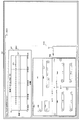
- FIG. 2 is a diagram illustrating an example of a screen displayed on the display in the sensor information processing system according to the first embodiment of the present invention.
- FIG. 3 is a diagram illustrating an example of a sensor display area included in a screen displayed on the display in the sensor information processing system according to the first embodiment of the present invention.
- FIG. 4 is a diagram showing an example of an initial display of the sensor display area included in the screen displayed on the display in the sensor information processing system according to the first embodiment of the present invention.
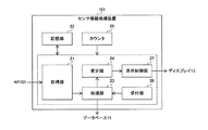
- FIG. 5 is a diagram showing a configuration of the sensor information processing apparatus in the sensor information processing system according to the first embodiment of the present invention.
- FIG. 1 is a diagram showing a configuration of a sensor information processing system according to a first embodiment of the present invention.
- FIG. 2 is a diagram illustrating an example of a screen displayed on the display in the sensor information processing system according to the first embodiment of
- FIG. 6 is a diagram for explaining the principle of estimating the relative position of the sensor with respect to the AP using the TOA in the sensor information processing system according to the first embodiment of the present invention.
- FIG. 7 is a diagram for explaining the principle of estimating the relative position of the sensor with respect to the AP using TDOA in the sensor information processing system according to the first embodiment of the present invention.
- FIG. 8 is a diagram for explaining the principle of estimating the relative position of the sensor with respect to the AP using the AOA in the sensor information processing system according to the first embodiment of the present invention.
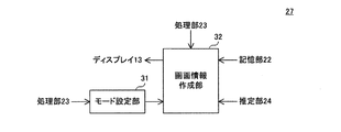
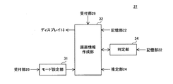
- FIG. 9 is a diagram showing the configuration of the display control unit in the sensor information processing apparatus according to the first embodiment of the present invention.
- FIG. 10 is a flowchart defining an operation procedure when the sensor information processing apparatus according to the first embodiment of the present invention performs estimation processing and performs control to display a sensor icon on the screen.
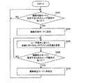
- FIG. 11 is a flowchart defining an operation procedure when the sensor information processing apparatus according to the first embodiment of the present invention switches its operation mode to change the position of the sensor icon on the screen.
- FIG. 12 is a diagram showing a configuration of a display control unit in the sensor information processing apparatus according to the second embodiment of the present invention.
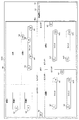
- FIG. 13 is a diagram illustrating an example of a sensor display area included in the screen displayed on the display in the sensor information processing system according to the second embodiment of the present invention.
- FIG. 14 is a flowchart defining an operation procedure when the sensor information processing apparatus according to the second embodiment of the present invention performs estimation processing and performs control to display a sensor icon on the screen.
- FIG. 15 is a diagram showing the configuration of the display control unit in the sensor information processing apparatus according to the third embodiment of the present invention.
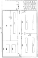
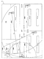
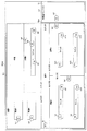
- FIG. 16 is a diagram illustrating an example of a sensor display area included in a screen to be displayed on a display created by the screen information creation unit in the sensor information processing system according to the third embodiment of the present invention.
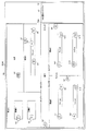
- FIG. 17 is a diagram illustrating an example of a sensor display area included in a screen displayed on the display in the sensor information processing system according to the third embodiment of the present invention.
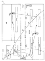
- FIG. 18 is a diagram illustrating an example of a sensor display area included in a screen displayed on the display in the sensor information processing system according to the third embodiment of the present invention.
- FIG. 19 is a diagram illustrating an example of a sensor display area included in a screen displayed on the display in the sensor information processing system according to the third embodiment of the present invention.
- FIG. 20 is a diagram illustrating an example of a sensor display area included in a screen displayed on the display in the sensor information processing system according to the third embodiment of the present invention.
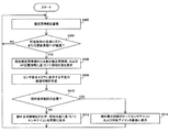
- FIG. 21 is a flowchart that defines an operation procedure when the sensor information processing apparatus according to the third embodiment of the present invention performs estimation processing and performs control to display sensor icons on the screen and exception display control.
- a sensor information processing apparatus obtains estimation information obtained from radio waves received from the sensor by the wireless communication apparatus from a wireless communication apparatus capable of performing wireless communication with the sensor.
- An acquisition unit to acquire, an estimation unit to estimate a relative position of the sensor with respect to the wireless communication device based on the estimation information acquired by the acquisition unit, and position information of the wireless communication device, and the estimation unit
- a display control unit that performs control to display an icon indicating the position of the sensor on the screen based on the relative position estimated by the above.
- the position where the icon should be displayed on the screen can be estimated more correctly by the configuration that estimates the relative position of the sensor using information obtained from the transmission radio wave of the sensor. Icons can be displayed automatically. Therefore, the icon indicating the sensor can be displayed at an appropriate position on the screen while reducing the burden on the user.
- the sensor information processing apparatus further includes a reception unit that receives a user operation, and the display control unit changes the position of the icon on the screen according to the operation received by the reception unit. To do.
- This configuration allows the icon to be moved to an appropriate position on the screen even when the accuracy of the relative position estimation result by the estimation unit is not sufficient.
- the estimation unit estimates the relative position when a predetermined condition is satisfied.
- the predetermined condition is that the user has instructed or the time specified by the user has come.
- the relative position can be estimated at the timing desired by the user.
- the estimation unit updates the relative position every time a predetermined time elapses.
- the latest sensor arrangement can be reflected on the screen.
- the predetermined condition is that the sensor has moved, or that the sensor to be displayed has been added or deleted.
- a physical change related to an actual sensor can be used as a trigger to automatically reflect the change on the display content of the screen.
- the display control unit can switch between an operation mode in which the position of the icon is changed according to the operation and an operation mode in which the position of the icon is not changed regardless of the operation.
- the display control unit further performs control to display information indicating the accuracy of the relative position on the screen.
- the user can easily recognize the degree of correctness of the relative position estimation result obtained by the sensor information processing apparatus.
- the sensor information processing apparatus further includes an accumulation unit that accumulates the estimation information acquired by the acquisition unit, and the estimation unit is configured so that the wireless communication device is in a predetermined time or a predetermined period.
- the estimation information obtained from the received radio wave is acquired from the storage unit, and the relative position is estimated based on the acquired estimation information and the position information.
- the relative position of the sensor can be estimated using information obtained from radio waves received from the sensor by the wireless communication apparatus at a time or period appropriate for use in estimation of the relative position.
- the display control unit sets the target icon that is the corresponding icon as the relative position. Exception display control is performed to display the sensor information on the screen in a position or manner different from the display based on the display.
- the display control unit further performs control to display a list of the sensors not displaying the icon on the screen, and the relative position is set to the non-placeable area as the exception display control. The included sensor is added to the list.
- the display control unit displays warning information on the screen as the exception display control.
- the user can more easily recognize from the warning information that there is an icon that is not displayed at an appropriate position on the screen.
- the display control unit displays the target icon on the screen in a different manner as the exception display control.
- the user can more easily recognize an icon that is not displayed at an appropriate position on the screen from the display mode of the icon.
- the display control unit arranges the target icon in an arrangementable area where the sensor can be arranged as the exception display control.
- an icon that is not displayed at an appropriate position on the screen can be automatically displayed at an appropriate position in the vicinity, for example.
- a sensor information processing method is a sensor information processing method in a sensor information processing device, wherein the wireless communication device is a wireless communication device capable of performing wireless communication with a sensor. Based on the obtained estimation information obtained from the radio wave received from the sensor, the obtained estimation information, and the position information of the wireless communication device, the relative position of the sensor to the wireless communication device is estimated. And a step of performing control to display an icon indicating the position of the sensor on the screen based on the estimated relative position.
- the position where the icon should be displayed on the screen can be estimated more correctly by the configuration that estimates the relative position of the sensor using information obtained from the transmission radio wave of the sensor. Icons can be displayed automatically. Therefore, the icon indicating the sensor can be displayed at an appropriate position on the screen while reducing the burden on the user.
- a sensor information processing program is a sensor information processing program used in a sensor information processing apparatus, from a wireless communication apparatus capable of performing wireless communication with a sensor to a computer, The wireless communication device acquires the estimation information obtained from the radio wave received from the sensor, and the sensor with respect to the wireless communication device based on the acquired estimation information and the position information of the wireless communication device.
- the position where the icon should be displayed on the screen can be estimated more correctly by the configuration that estimates the relative position of the sensor using information obtained from the transmission radio wave of the sensor. Icons can be displayed automatically. Therefore, the icon indicating the sensor can be displayed at an appropriate position on the screen while reducing the burden on the user.
- FIG. 1 is a diagram showing a configuration of a sensor information processing system according to a first embodiment of the present invention.
- a sensor information processing system 301 includes a display 13, a database 71, 14 sensors 121A to 121N, four access points (wireless communication devices) 151A to 151D, and a sensor information processing device. 101.
- each of the sensors 121A to 121N is also referred to as a sensor 121.
- Each of the access points 151A to 151D is also referred to as an access point 151.
- Access point 151 is also referred to as AP 151.
- FIG. 1 representatively shows 14 sensors 121, but a larger or smaller number of sensors 121 may be provided. Further, four APs 151 are representatively shown, but a larger or smaller number of APs 151 may be provided.
- the sensors 121A to 121N have S1 to S14 as their own IDs (hereinafter also referred to as sensor IDs), for example.
- the sensor 121 is arranged in a predetermined area, specifically, a monitoring target area such as a factory, a hospital, or a store.
- the monitoring target area is indoors, for example. Note that the monitoring target area may be outdoors.
- the sensor 121 measures illuminance, humidity, current, voltage, concentration, acceleration, gyroscope, pressure, and the like related to production equipment. For example, the sensor 121 creates sensor information including a measurement result and a sensor ID, and transmits a wireless signal including the created sensor information to the AP 151. More specifically, the sensor 121 broadcasts a sensor packet that stores sensor information, for example.
- APs 151A to 151D have AP1 to AP4 as their own IDs (hereinafter also referred to as APIDs), for example.
- APIDs their own IDs
- the APs 151A to 151D transmit the received sensor packet to the sensor information processing apparatus 101 via the LAN 10. Communication between the AP 151 and the sensor information processing apparatus 101 may be performed in a wired manner or wirelessly.
- the sensor information processing apparatus 101 when the sensor information processing apparatus 101 receives a sensor packet from the AP 151, the sensor information processing apparatus 101 acquires a measurement result and a sensor ID from the sensor information stored in the received sensor packet, and associates the acquired measurement result with the sensor ID in the database 71. To accumulate.
- the sensor information processing apparatus 101 can display the content of the received sensor information on the display 13, for example.
- FIG. 2 is a diagram illustrating an example of a screen displayed on the display in the sensor information processing system according to the first embodiment of the present invention.
- the browser Br1 is displayed on the screen.
- the browser Br1 includes, for example, an address display area ADA1, a graph display area GDA1, and a sensor display area SDA1.
- an address bar indicating a URL (Uniform Resource Locator) for displaying the graph Gr1, the map Map of the factory F1, and the unplaced sensor list Lt in the browser Br1 is displayed.
- FIG. 3 is a diagram showing an example of a sensor display area included in the screen displayed on the display in the sensor information processing system according to the first embodiment of the present invention.
- FIG. 3 shows an enlarged view of the sensor display area SDA1 shown in FIG.
- sensor display area SDA1 includes, for example, map area MA and list area LA.
- a map Map of the factory F1 which is the monitoring target area is displayed.
- a factory layout an icon indicating the sensor 121 (hereinafter also referred to as a sensor icon), and an icon indicating the AP 151 (hereinafter also referred to as an AP icon) are displayed in the map area MA.
- the outline of the rooms A to D, the outline of the hallway, the outline of the courtyard, the outline of the facilities A and B, and the outline of the lines A to E are displayed as the factory layout.
- sensor icons Is1 to Is14 are displayed as sensor icons.
- S1 to S14 which are sensor IDs of the corresponding sensors 121, are respectively attached to the sensor icons Is1 to Is14.
- AP icons Ia1 to Ia4 are displayed as AP icons.
- the AP icons are assigned AP1 to AP4, which are the APIDs of the corresponding APs 151, respectively.
- the sensor icon and the AP icon in the map area MA are positions corresponding to actual positions in the factory F1 of the corresponding sensors 121 and AP 151, for example (hereinafter also referred to as target display positions). Displayed).
- the sensor 121A having the ID of S1 is actually provided on the opposite side of the courtyard in the facility A of the factory F1.
- the sensor icon Is1 is displayed at a target display position on the opposite side of the outer shape of the courtyard in the outer shape of the facility A.
- the AP 151A having the ID of AP1 is actually provided on the opposite side of the room C or D in the hallway of the factory F1.
- the AP icon Ia1 is displayed at the target display position on the opposite side of the outline of the room C or the outline of the room D in the outline of the hallway.
- the sensor icons Is2 to Is14 are also displayed at the target display positions in the same manner as the sensor icon Is1. Further, the AP icons Ia2 to Ia4 are also displayed at the target display positions similarly to the AP icon Ia1.
- the map area MA has four entrances A to D between the rooms A to D and the hallway, one entrance E between the room B and the room D, and one entrance between the hallway and the outside. Each F is displayed.
- an unallocated sensor list Lt for accommodating sensor icons that are registered and not displayed in the map area MA is displayed.
- a graph Gr ⁇ b> 1 showing a time change of a measurement result by the sensor 121 is displayed in the graph display area GDA ⁇ b> 1.
- the horizontal axis is time
- the vertical axis is temperature.
- the graph Gr1 shows the time change of the temperature data DT1 measured by the sensor 121C having the sensor ID of S3, for example.
- the user recognizes that an abnormality has occurred in the measurement target line A of the sensor 121C. Then, for example, the user refers to the map area MA shown in FIG. 3 and confirms that the sensor 121C is located on the room A side of the line A in the room C, and moves to the actual position of the sensor 121C to detect an abnormality in the line A. To deal with.
- FIG. 4 is a diagram showing an example of an initial display of the sensor display area included in the screen displayed on the display in the sensor information processing system according to the first embodiment of the present invention.
- the display contents of the sensor display area SDA0 shown in FIG. 4 are the same as the display contents of the sensor display area SDA1 shown in FIG. 3 except for the contents described below.
- sensor icons Is1 to Is14 are displayed in list area LA as compared with sensor display area SDA1 shown in FIG.
- the user clicks and selects one of the sensor icons Is1 to Is14 displayed in the list area LA, drags the selected sensor icon to the corresponding target display position, and drops it at the target display position. Is possible.
- the user clicks and selects the sensor icon Is1 displayed in the list area LA, and selects the selected sensor icon Is1 in the outer shape of the courtyard in the outer shape of the equipment A that is the corresponding target display position. Drag to the opposite side and drop at the target display position.
- the user can display the sensor icon Is1 displayed in the list area LA in FIG. 4 at the target display position in the map area MA as shown in FIG.
- the senor 121 can receive a radio wave transmitted from a GPS (Global Positioning System) satellite, and calculate coordinates indicating a position where the sensor 121 is present based on the received radio wave.
- GPS Global Positioning System
- the sensor information processing system 301 solves such a problem by the following configuration and operation.
- FIG. 5 is a diagram showing a configuration of the sensor information processing apparatus in the sensor information processing system according to the first embodiment of the present invention.
- sensor information processing apparatus 101 includes acquisition unit 21, storage unit (storage unit) 22, processing unit 23, estimation unit 24, counter 25, reception unit 26, and display control unit. 27.
- the storage unit 22 holds, for example, factory layout information, AP position information, and sensor basic information. Moreover, the memory
- the counter 25 counts, for example, clock pulses generated by an oscillation circuit using a crystal resonator, and holds the counted value.
- the accepting unit 26 accepts a user operation, for example. More specifically, for example, the reception unit 26 receives an operation performed by the user on the screen of the display 13 and outputs operation information indicating the received content to the processing unit 23.
- the acquiring unit 21 acquires sensor information from the received sensor packet and outputs the acquired sensor information to the processing unit 23.
- the processing unit 23 when receiving the sensor information from the acquisition unit 21, the processing unit 23 acquires a measurement result and a sensor ID from the received sensor information, and stores the acquired measurement result in the database 71 in association with the sensor ID.
- the user first registers the factory layout in the monitoring target area and the AP 151 provided in the factory F1 in the sensor information processing apparatus 101.
- the user performs operations for inputting the external shapes of the rooms A to D, the external shape of the hallway, the external shape of the courtyard, the external shapes of the facilities A and B, and the external shapes of the lines A to E shown in FIG. To the reception unit 26.
- the user performs an operation for inputting the position of the AP 151 arranged in the factory F1 or the position and orientation of the AP 151 and the APID and type of the AP 151 on the reception unit 26.
- the accepting unit 26 creates, for example, operation information based on the user's operation, and outputs the created operation information to the processing unit 23.
- the processing unit 23 for example, based on the operation information received from the receiving unit 26, the outer shape of the rooms A to D, the outer shape of the hallway, the outer shape of the courtyard, the outer shapes of the facilities A and B, and the lines A to E shown in FIG.
- the factory layout information indicating the external shape of the factory is created, and the created factory layout information is stored in the storage unit 22.
- the processing unit 23 creates AP position information including the position of the AP 151 or the position and orientation and the APID of the AP 151, and the created AP position information
- the data is stored in the storage unit 22.
- the sensor 121 when the sensor 121 is turned on by the user, the sensor 121 starts transmitting sensor information including a measurement result and a sensor ID.
- the processing unit 23 monitors, for example, the sensor ID included in the sensor information received from the acquisition unit 21, and performs the detection process of the sensor 121 that is newly turned on based on the monitoring result. For example, when detecting the sensor 121 that is newly turned on, the processing unit 23 registers the detected sensor 121. Specifically, for example, the processing unit 23 creates sensor basic information indicating the sensor ID and the type based on the sensor information, and causes the storage unit 22 to hold the created sensor basic information.
- the sensor 121 when the sensor 121 is turned off by the user, the sensor 121 stops transmitting sensor information and transmits operation stop information including its own sensor ID. At this time, the sensor 121 transmits operation stop information using, for example, power stored in a capacitor or the like.
- the acquisition unit 21 when receiving the operation stop information from the sensor 121 via the AP 151, the acquisition unit 21 outputs the received operation stop information to the processing unit 23.
- the processing unit 23 acquires the sensor ID from the received operation stop information and deletes the sensor 121 indicated by the acquired sensor ID.
- the basic information is deleted from the storage unit 22.
- the processing unit 23 deletes the sensor 121 by performing the following processing.
- the processing unit 23 monitors the sensor ID included in the sensor information received from the acquisition unit 21, and performs detection processing of the sensor ID that has not been received from the acquisition unit 21 for a predetermined time or more based on the monitoring result. For example, when the processing unit 23 detects a sensor ID that has not been received from the acquisition unit 21 for a predetermined time or longer, the processing unit 23 deletes the sensor 121 indicated by the detected sensor ID. Specifically, the corresponding sensor basic information is stored from the storage unit 22. to erase.
- the registration and deletion of the sensor 121 with respect to the sensor information processing apparatus 101 are not limited to a configuration in which the sensor 121 is automatically performed according to the on / off state of the sensor 121, but may be a configuration performed by a user.
- the acquisition unit 21 acquires information for estimation obtained from radio waves received from the sensor 121 by the AP 151 from the AP 151 capable of performing wireless communication with the sensor 121.
- the acquisition unit 21 acquires the estimation information from the AP 151
- the acquisition unit 21 acquires a count value from the counter 25, and stores the acquired estimation information in the storage unit 22 together with the acquired count value (hereinafter also referred to as acquisition time). accumulate.
- the estimation unit 24 performs an estimation process for estimating the relative position of the sensor 121 with respect to the AP 151 based on the estimation information acquired by the acquisition unit 21 and the position information of the AP 151.
- the estimation unit 24 when the estimation unit 24 receives the estimation command from the processing unit 23 as the estimation process, the estimation unit 24 acquires the estimation information corresponding to the acquisition time corresponding to the content of the received estimation command and the AP position information from the storage unit 22. Based on the obtained estimation information and AP position information, the relative position of the sensor 121 with respect to the AP 151 is estimated.
- sensor information processing system 301 estimates the relative position of sensor 121 with respect to AP 151 using TOA (Time Of Arrival).
- TOA Time Of Arrival
- the sensor 121 and the AP 151 include the same counter as the counter 25, and these counters are synchronized.
- the senor 121 transmits a packet to three or more APs 151. At this time, the sensor 121 stores the transmission time information indicating the time based on its own counter and the time when the packet is transmitted, and its own sensor ID in the packet.
- the three or more APs 151 Upon receiving a packet from the sensor 121, the three or more APs 151 store reception time information indicating a time based on its own counter and the time when the packet is received, and its own APID in the packet, and sensor information Each is transmitted to the processing apparatus 101.
- the packet transmitted from the sensor 121 to the sensor information processing apparatus 101 via the AP 151 may be a sensor packet or a dedicated packet.
- FIG. 6 is a diagram for explaining the principle of estimating the relative position of the sensor with respect to the AP using the TOA in the sensor information processing system according to the first embodiment of the present invention.
- FIG. 6 shows a plan view of the actual factory F1.
- the sensor 121A transmits a packet to the APs 151A to 151D.
- the AP 151A to 151D transmits the received packet to the sensor information processing apparatus 101 via the LAN 10.
- transmission time information, sensor ID, reception time information, and APID included in the packet transmitted in this way are accumulated as estimation information together with the acquisition time.
- the estimation unit 24 when the estimation unit 24 receives an estimation command from the processing unit 23, the relative position of the sensor 121 with respect to the AP 151 based on the estimation information corresponding to the acquisition time corresponding to the content of the received estimation command and the AP position information. Is estimated.
- the estimation unit 24 requires, for example, the transmission of radio waves including a packet from the sensor 121A to the AP 151A based on estimation information, that is, transmission time information, sensor ID, reception time information, and APID. Calculate time. For example, the estimating unit 24 calculates the distance Daa between the sensor 121A and the AP 151A by dividing the calculated required time by the speed of light.
- the estimation unit 24 calculates the distances Dab to Dad between the sensor 121A and the APs 151B to 151D based on the estimation information, for example.
- the estimator 24 uses, for example, the calculated distances Dab to Dad and the positions of APs 151A to 151D indicated by the AP position information to form four circles centered on the positions of APs 151A to 151D and having radii Dab to Dad. An intersection Pa1 of four circles each having a radius is calculated.
- the estimation unit 24 estimates, for example, the relative position of the intersection Pa1 with respect to the positions of the APs 151A to 151D as the relative position of the sensor 121A with respect to the APs 151A to 151D. For example, the estimation unit 24 creates relative position information including the estimated relative position and the sensor ID of the sensor 121 ⁇ / b> A, and outputs the created relative position information to the display control unit 27.
- the estimation unit 24 can estimate the relative position of the sensor 121 with respect to the AP 151 in two dimensions based on estimation information from at least three APs 151, that is, with respect to the AP 151 when the factory F1 is viewed in plan.
- the relative position of the sensor 121 can be estimated.
- the estimation unit 24 can estimate the relative position of the sensor 121 with respect to the AP 151 in a three-dimensional manner based on, for example, information for estimation from at least four APs 151.
- the estimation unit 24 estimates the relative positions of the sensors 121B to 121N with respect to the AP 151 in the same manner as the relative position of the sensor 121A with respect to the AP 151.
- Estimatment method 2 Referring to FIG. 1 again, for example, the sensor information processing system 301 estimates the relative position of the sensor 121 with respect to the AP 151 using TDOA (Time Difference Of Arrival).
- TDOA Time Difference Of Arrival
- each AP 151 includes a counter similar to the counter 25, and these counters are synchronized.
- the sensor 121 transmits a packet to two or more APs 151.
- the two or more APs 151 receive a packet from the sensor 121
- the two or more APs 151 store reception time information indicating the time based on the counter and the time when the packet is received and their own APID in the packet, and the sensor information processing apparatus 101 respectively.
- the packet transmitted from the sensor 121 to the sensor information processing apparatus 101 via the AP 151 may be a sensor packet or a dedicated packet.
- FIG. 7 is a diagram for explaining the principle of estimating the relative position of the sensor with respect to the AP using TDOA in the sensor information processing system according to the first embodiment of the present invention. 7 is the same as FIG.
- the sensor 121A transmits a packet to the APs 151A to 151C.
- each of the APs 151A to 151C when receiving a packet from the sensor 121A, transmits the received packet to the sensor information processing apparatus 101 via the LAN 10.
- reception time information and APID included in the packet transmitted in this manner are accumulated as estimation information together with an acquisition time.
- the estimation unit 24 when the estimation unit 24 receives an estimation command from the processing unit 23, the relative position of the sensor 121 with respect to the AP 151 based on the estimation information corresponding to the acquisition time corresponding to the content of the received estimation command and the AP position information. Is estimated.
- the estimation unit 24 calculates the difference between the times at which the APs 151A and 151B received the radio waves transmitted from the sensor 121A based on the estimation information, that is, the reception time information and the APID.
- the distance difference Ds is calculated by dividing the difference by the speed of light.
- the estimation unit 24 calculates, for example, a hyperbola HPs that is a point Ps that is a distance Das away from the AP 151A and a locus of the point Ps that is a distance Dbs away from the AP 151B.
- the magnitude of the difference between the distance Das and the distance Dbs is the distance difference Ds.
- the hyperbola HPs passes through the sensor 121A.
- the estimation unit 24 calculates, for example, the difference between the times at which the APs 151B and 151C received the radio wave transmitted from the sensor 121A based on the reception time information and APID included in the estimation information, and The distance difference Dt is calculated by dividing the difference by the speed of light.
- the estimation unit 24 calculates, for example, a hyperbola HPt that is a locus of a point Pt that is a distance Dbt from the AP 151B and that is a distance Dct from the AP 151C.
- the magnitude of the difference between the distance Dbt and the distance Dct is the distance difference Dt.
- the hyperbola HPt passes through the sensor 121A.
- the estimation unit 24 calculates, for example, the difference between the times at which the APs 151C and 151A received the radio wave transmitted from the sensor 121A based on the reception time information and APID included in the estimation information, and The distance difference Du is calculated by dividing the difference by the speed of light.
- the estimation unit 24 calculates, for example, a hyperbola HPu that is a point Pu that is a distance Dcu away from the AP 151C and a point Pu that is away from the AP 151A by a distance Dau.
- the magnitude of the difference between the distance Dcu and the distance Dau is the distance difference Du.
- the hyperbola HPu passes through the sensor 121A.
- the estimation unit 24 calculates, for example, the intersection Pa2 of the calculated hyperbola HPs, HPt, HPu, and estimates the relative position of the intersection Pa2 with respect to the positions of the APs 151A to 151C as the relative position of the sensor 121A with respect to the APs 151A to 151C.
- the estimation unit 24 creates relative position information including the estimated relative position and the sensor ID of the sensor 121 ⁇ / b> A, and outputs the created relative position information to the display control unit 27.
- the estimation unit 24 can estimate the relative position of the sensor 121 with respect to the AP 151 in two dimensions based on, for example, information for estimation from at least two APs 151.
- the estimation unit 24 can estimate the relative position of the sensor 121 with respect to the AP 151 in a three-dimensional manner based on, for example, information for estimation from at least three APs 151.
- the estimation unit 24 estimates the relative positions of the sensors 121B to 121N with respect to the AP 151 in the same manner as the relative position of the sensor 121A with respect to the AP 151.
- Estimatiation method 3 Referring to FIG. 1 again, for example, in sensor information processing system 301, the relative position of sensor 121 with respect to AP 151 is estimated using AOA (Angle Of Arrival).
- AOA Angle Of Arrival
- each AP 151 can measure the arrival direction of radio waves from the sensor 121.
- the sensor 121 transmits radio waves to two or more APs 151.
- the two or more APs 151 receive a radio wave from the sensor 121
- the two or more APs 151 measure an arrival angle that is an angle with respect to the direction of the received radio wave, and receive the measurement result and the arrival angle information indicating the own APID. To each.
- FIG. 8 is a diagram for explaining the principle of estimating the relative position of the sensor with respect to the AP using the AOA in the sensor information processing system according to the first embodiment of the present invention.
- the view of FIG. 8 is the same as that of FIG.
- the sensor 121A transmits radio waves to the APs 151A and 151B.
- the AP 151A measures an arrival angle ⁇ a that is an angle of the received radio wave with respect to its own direction Na, and sends the measurement result and arrival angle information indicating its own APID to the sensor information processing apparatus 101. Send.
- the AP 151B when the AP 151B receives a radio wave from the sensor 121A, the AP 151B measures an arrival angle ⁇ b that is an angle of the received radio wave with respect to its own direction Nb, and sends the measurement result and arrival angle information indicating its own APID to the sensor information processing apparatus 101. Send.
- the arrival angle information transmitted in this way is stored as estimation information together with the acquisition time.
- the estimation unit 24 when the estimation unit 24 receives an estimation command from the processing unit 23, the relative position of the sensor 121 with respect to the AP 151 based on the estimation information corresponding to the acquisition time corresponding to the content of the received estimation command and the AP position information. Is estimated.
- the estimation unit 24 acquires a line segment Laa starting from the position of the AP 151A and extending in the direction of the arrival angle ⁇ a with respect to the direction Na of the AP 151A.
- the estimation unit 24 acquires a line segment Lba starting from the position of the AP 151B and extending in the direction of the arrival angle ⁇ b with respect to the direction Nb of the AP 151B.
- the estimation unit 24 calculates, for example, the intersection Pa3 of the line segments Laa and Lba. For example, the estimating unit 24 estimates the relative position of the intersection Pa3 with respect to the positions of the APs 151A and 151B as the relative position of the sensor 121A with respect to the APs 151A and 151B. For example, the estimation unit 24 creates relative position information including the estimated relative position and the sensor ID of the sensor 121 ⁇ / b> A, and outputs the created relative position information to the display control unit 27.
- the estimation unit 24 determines the relative position of the sensor 121 with respect to the AP 151 in two dimensions based on the estimation information from at least two APs 151. It can be estimated.
- the estimation unit 24 can estimate the relative position of the sensor 121 with respect to the AP 151 in three dimensions based on, for example, information for estimation from at least two APs 151. is there.
- the estimation unit 24 estimates the relative positions of the sensors 121B to 121N with respect to the AP 151 in the same manner as the relative position of the sensor 121A with respect to the AP 151.
- Estimatiation method 4 In the sensor information processing system 301, for example, the relative position of the sensor 121 with respect to the AP 151 is estimated using RSSI (Received Signal Strength Indication) indicating reception intensity.
- RSSI Receiveived Signal Strength Indication
- the sensor 121 transmits a packet to three or more APs 151.
- the three or more APs 151 measure the RSSI at the time of receiving the packet, and transmit the RSSI information indicating the measurement result and its own APID to the sensor information processing apparatus 101.
- sensor 121A transmits a packet to APs 151A to 151D.
- each of APs 151A to 151D measures RSSI at the time of packet reception, and transmits a packet storing RSSI information indicating the measurement result and its own APID to sensor information processing apparatus 101 via LAN 10.
- the packet transmitted from the sensor 121A to the sensor information processing apparatus 101 via the APs 151A to 151D may be a sensor packet or a dedicated packet.
- the RSSI information included in the packet transmitted in this way is accumulated as the estimation information together with the acquisition time.
- the estimation unit 24 when the estimation unit 24 receives an estimation command from the processing unit 23, the relative position of the sensor 121 with respect to the AP 151 based on the estimation information corresponding to the acquisition time corresponding to the content of the received estimation command and the AP position information. Is estimated.
- the estimation unit 24 recognizes the transmission power of the sensors 121A to 121N, for example. For example, the estimation unit 24 calculates the distance Daa between the sensor 121A and the AP 151A based on the transmission power of the sensor 121A and the estimation information.
- the estimation unit 24 calculates the distances Dab to Dad between the sensor 121A and the APs 151B to 151D based on, for example, the transmission power of the sensor 121A and the estimation information.
- the estimation unit 24 calculates the intersection Pa1 from the distances Dab to Dad and the AP position information, for example, in the same manner as the above-described estimation method 1. For example, the estimating unit 24 estimates the relative position of the intersection Pa1 with respect to the positions of the APs 151A to 151D as the relative position of the sensor 121A with respect to the APs 151A to 151D. For example, the estimation unit 24 creates relative position information including the estimated relative position and the sensor ID of the sensor 121 ⁇ / b> A, and outputs the created relative position information to the display control unit 27.
- the estimation unit 24 estimates the relative positions of the sensors 121B to 121N with respect to the AP 151 in the same manner as the relative position of the sensor 121A with respect to the AP 151.
- estimation unit 24 may estimate the relative position of the sensor 121 with respect to the AP 151 by combining some or all of the estimation methods 1 to 4, for example.
- the accepting unit 26 creates, for example, operation information based on the user's operation, and outputs the created operation information to the processing unit 23.
- the processing unit 23 outputs, to the display control unit 27, an initial display creation command for displaying the browser Br1 including the initial display of the sensor display area on the display 13 based on the operation information received from the reception unit 26, for example.
- FIG. 9 is a diagram showing a configuration of a display control unit in the sensor information processing apparatus according to the first embodiment of the present invention.
- the display control unit 27 includes a mode setting unit 31 and a screen information creation unit 32.
- the screen information creation unit 32 in the display control unit 27 performs the following processing based on the received initial display creation command.
- the screen information creation unit 32 acquires, for example, factory layout information, AP position information, and sensor basic information from the storage unit 22, and based on the acquired factory layout information, AP position information, and sensor basic information in FIG. Screen information for displaying the browser Br1 including the sensor display area SDA0 shown in FIG. 4 instead of the sensor display area SDA1 is created. Then, the screen information creation unit 32 performs control to display the created screen information on the display 13, for example.
- Estimatimation trigger (User specified or directed) For example, the estimation unit 24 estimates the relative position when the predetermined condition EC is satisfied.
- the predetermined condition EC is, for example, an instruction from the user or a time specified by the user.
- the user when the user newly arranges the sensors 121A to 121N in the factory F1 and displays the browser Br1 including the sensor display area SDA0 shown in FIG. 4, the user immediately estimates the position of the sensor 121.
- an operation for immediately starting the estimation of the position of the sensor 121 is performed on the reception unit 26.
- the accepting unit 26 creates, for example, operation information based on the user's operation, and outputs the created operation information to the processing unit 23.
- the processing unit 23 performs estimation processing based on estimation information acquired at the latest acquisition time (hereinafter also referred to as latest estimation information) based on operation information received from the reception unit 26.
- the estimation command is output to the estimation unit 24.
- the user estimates the position of the sensor 121 at the designated time.
- An operation for starting is performed on the reception unit 26.
- the accepting unit 26 creates, for example, operation information based on the user's operation, and outputs the created operation information to the processing unit 23.
- the processing unit 23 monitors the count value in the counter 25 based on the operation information received from the receiving unit 26, and performs the following processing at the timing when the monitored count value indicates the time designated by the user.
- the processing unit 23 outputs, for example, an estimation command for performing an estimation process based on the latest estimation information to the estimation unit 24.
- the estimation unit 24 determines that the predetermined condition EC is satisfied, and performs estimation processing according to the received estimation command.
- the predetermined condition EC is, for example, that the sensor 121 has moved, or that the sensor 121 to be displayed has been added or deleted.
- the sensor 121 shown in FIG. 1 has a function of measuring acceleration and measures its own acceleration.
- the sensor 121 includes its own acceleration measurement result in the sensor information and transmits it to the sensor information processing apparatus 101 via the AP 151.
- the processing unit 23 monitors the measurement result.
- the processing unit 23 determines that the sensor 121 has moved, and estimates an estimation command for performing an estimation process based on the latest estimation information. To the unit 24.
- the configuration is not limited to the above, and the sensor 121 may be configured to determine whether the acceleration measurement result of the sensor 121 is equal to or greater than a predetermined threshold value.
- the sensor 121 transmits the determination result to the sensor information processing apparatus 101.
- the processing unit 23 outputs an estimation command to the estimation unit 24 when the determination result received via the acquisition unit 21 indicates that the measurement result of acceleration in the sensor 121 is equal to or greater than a predetermined threshold value.
- the processing unit 23 when the sensor 121 is registered or when the sensor 121 is deleted, the processing unit 23 outputs an estimation command for performing an estimation process based on the latest estimation information to the estimation unit 24. To do.
- the processing unit 23 registers or deletes the sensor 121, the sensor 121 to be displayed is added or deleted, so that the predetermined condition EC is satisfied.
- the estimation unit 24 determines that the predetermined condition EC is satisfied, and performs estimation processing according to the received estimation command.
- the estimation unit 24 updates the relative position every time a predetermined time elapses.
- the position of the sensor 121 is estimated at a predetermined update period T1. An operation is performed on the reception unit 26.
- the accepting unit 26 creates, for example, operation information based on the user's operation, and outputs the created operation information to the processing unit 23.
- the processing unit 23 monitors the count value in the counter 25 based on the operation information received from the reception unit 26, and when the monitored count value indicates the start timing of the predetermined update cycle T1, the latest estimation information An estimation command for performing an estimation process based on the above is output to the estimation unit 24.
- the estimation unit 24 when the estimation unit 24 receives an estimation command from the processing unit 23, the estimation unit 24 performs an estimation process according to the received estimation command.
- the estimation unit 24 acquires estimation information obtained from the radio waves received by the AP 151 at a predetermined time or period from the storage unit 22 and estimates the relative position based on the acquired estimation information and the position information of the AP 151. To do.
- the estimating unit 24 for example, instead of the latest estimation information, estimation information obtained from the radio wave received by the AP 151 at a time or period specified by the user (hereinafter also referred to as designated estimation information). .) Is acquired from the storage unit 22, and the relative position is estimated based on the acquired designation estimation information and the position information of the AP 151.
- the radio wave transmission environment is stabilized, so that the estimation accuracy of the relative position by the estimation unit 24 may be improved.
- the user receives an operation for starting estimation of the position of the sensor 121 based on the information for estimation estimation corresponding to a predetermined acquisition time or the information for estimation estimation corresponding to the acquisition time included in a predetermined period. 26.
- the timing at which the user operates the reception unit 26 may be any timing.
- the estimation unit 24 determines that the predetermined condition EC that is instructed by the user is satisfied.
- the accepting unit 26 creates, for example, operation information based on the user's operation, and outputs the created operation information to the processing unit 23.
- the processing unit 23 outputs, to the estimation unit 24, an estimation command for performing an estimation process based on the designated estimation information based on the operation information received from the reception unit 26, for example.
- the estimation unit 24 when the estimation unit 24 receives an estimation command from the processing unit 23, the estimation unit 24 acquires specified estimation information from the storage unit 22 in accordance with the received estimation command, and performs an estimation process based on the acquired specified estimation information.
- the display control unit 27 performs control to display an icon indicating the position of the sensor 121 on the screen based on the relative position estimated by the estimation unit 24 as in the above examples.
- the display control unit 27 can switch between an operation mode in which the position of the icon is changed according to a user operation and an operation mode in which the icon position is not changed regardless of the user operation.
- the mode setting unit 31 in the display control unit 27 changes, for example, the operation mode of its own sensor information processing apparatus 101 to an edit inhibition mode that is an operation mode in which the position of the icon is not changed regardless of the user's operation. It is set by default.
- the display control unit 27 when the display control unit 27 receives the relative position information from the estimation unit 24 in the edit prohibit mode, the display control unit 27 sets the position in the sensor display area based on the relative position included in the received relative position information. Control is performed to automatically display a sensor icon corresponding to the sensor ID included in the relative position information.
- screen information creation unit 32 in the display control unit 27 performs control to display screen information for displaying the browser Br1 including the sensor display area SDA0 shown in FIG.
- screen information for displaying the browser Br1 including the sensor display area SDA1 shown in FIG. 3 is created.
- the screen information creation unit 32 performs control to display the created screen information on the display 13, for example.
- a user operation to change the display position of the sensor icon is not accepted, and the display position is fixed.
- the user performs an operation on the reception unit 26 for setting the operation mode of the sensor information processing apparatus 101 to an editable mode, which is an operation mode for changing the position of the sensor icon according to its own operation.
- the accepting unit 26 creates, for example, operation information based on the user's operation, and outputs the created operation information to the processing unit 23.
- the processing unit 23 outputs a mode change command for changing the operation mode of its own sensor information processing apparatus 101 to the editable mode to the mode setting unit 31 based on the operation information received from the receiving unit 26, for example.
- the mode setting unit 31 sets the operation mode of its own sensor information processing apparatus 101 to the editable mode according to the mode change command received from the processing unit 23, for example.
- the display control unit 27 changes the position of the icon on the screen according to the operation received by the receiving unit 26, for example.
- the user performs an operation on the reception unit 26 for moving the position of the sensor icon in the sensor display area.
- the accepting unit 26 creates, for example, operation information based on the user's operation, and outputs the created operation information to the processing unit 23.
- the processing unit 23 outputs, for example, a movement command for moving the position of the sensor icon in the sensor display area according to the user's operation to the screen information creation unit 32 based on the operation information received from the reception unit 26.
- the screen information creation unit 32 creates screen information in which the position of the sensor icon in the sensor display area is changed in accordance with, for example, a movement command received from the processing unit 23. Then, the screen information creation unit 32 performs control to display the created screen information on the display 13, for example.
- the user performs an operation for setting the edit prohibit mode on the reception unit 26.
- the operation mode of the sensor information processing apparatus 101 is changed to the edit prohibition mode, for example, a user who is not an administrator arbitrarily changes the position of the sensor icon in the sensor display area, or the user is unconscious. It is possible to prevent the position of the sensor icon in the sensor display area from being changed.
- the sensor information processing apparatus 101 includes a computer, and an arithmetic processing unit such as a CPU in the computer reads and executes a program including a part or all of each step of the following flowchart from a memory (not shown).
- the program of this apparatus can be installed from the outside.
- the program of this device is distributed in a state stored in a recording medium.
- FIG. 10 is a flowchart defining an operation procedure when the sensor information processing apparatus according to the first embodiment of the present invention performs estimation processing and performs control to display a sensor icon on the screen.
- sensor information processing apparatus 101 acquires information for estimation from AP 151 until predetermined condition EC is satisfied or update cycle T1 has elapsed (NO in step S104).
- the estimation information is accumulated in the storage unit 22 (step S102).
- step S104 when the predetermined condition EC is satisfied or the update cycle T1 has elapsed (YES in step S104), the sensor information processing apparatus 101 is based on the latest estimation information or the specified estimation information and the AP position information. An estimation process for estimating the relative position of the sensor 121 with respect to the AP 151 is performed (step S106).
- the sensor information processing apparatus 101 performs control to display a sensor icon on the screen of the display 13 based on the estimated relative position (step S108).
- the sensor information processing apparatus 101 acquires the estimation information from the AP 151 until the predetermined condition EC is satisfied or the update cycle T1 elapses (NO in step S104), and the acquired estimation information is stored in the storage unit. 22 (step S102).
- FIG. 11 is a flowchart defining an operation procedure when the sensor information processing apparatus according to the first embodiment of the present invention switches its operation mode to change the position of the sensor icon on the screen.
- the sensor information processing apparatus 101 is set to the edit prohibit mode by default.
- the sensor information processing apparatus 101 does not accept the user's operation for changing the icon position until the user's operation for setting the editable mode occurs (NO in step S202), and the operation occurs. Then (YES in step S202), its own operation mode is set to the editable mode (step S204).
- the sensor information processing apparatus 101 changes the position of the sensor icon on the screen of the display 13 in accordance with the user operation until an operation by the user for resetting to the edit prohibition mode occurs (NO in step S208). (Step S206).
- step S208 when an operation by the user for resetting to the edit prohibition mode occurs (YES in step S208), the sensor information processing apparatus 101 resets its own operation mode to the edit prohibition mode (step S210).
- the sensor information processing apparatus 101 does not accept an operation by the user for changing the position of the icon until an operation by the user for resetting to the editable mode occurs (NO in step S202).
- the arrangement of sensors in the predetermined area may be displayed on the screen.
- a plurality of icons respectively indicating a plurality of sensors are displayed at corresponding positions on the screen.
- the acquisition unit 21 receives radio waves received from the sensor 121 by the AP 151 from the AP 151 that can perform wireless communication with the sensor 121. Get estimation information obtained from.
- the estimation unit 24 estimates the relative position of the sensor 121 with respect to the AP 151 based on the estimation information acquired by the acquisition unit 21 and the AP position information.
- the display control unit 27 performs control to display an icon indicating the position of the sensor 121 on the screen based on the relative position estimated by the estimation unit 24.
- the configuration in which the relative position of the sensor 121 is estimated using the information obtained from the transmission radio wave of the sensor 121 can more accurately estimate the position where the icon should be displayed on the screen.
- An icon can be automatically displayed at the position. Therefore, the icon indicating the sensor can be displayed at an appropriate position on the screen while reducing the burden on the user.
- the reception unit 26 receives a user operation. Then, the display control unit 27 changes the position of the icon on the screen according to the operation received by the receiving unit 26.
- the icon can be moved to an appropriate position on the screen even when the accuracy of the estimation result of the relative position by the estimation unit 24 is not sufficient.
- the estimation unit 24 estimates the relative position when the predetermined condition EC is satisfied.
- the predetermined condition EC is that the user has instructed or the time specified by the user.
- the relative position can be estimated at the timing desired by the user.
- the estimation unit 24 updates the relative position every predetermined time, specifically, every time the update cycle T1 elapses.
- the relative position is automatically updated at each update cycle T1
- the latest arrangement of the sensor 121 can be reflected on the screen.
- the predetermined condition EC is that the sensor 121 has moved, or that the sensor 121 to be displayed has been added or deleted. is there.
- a physical change related to the actual sensor 121 can be used as a trigger to automatically reflect the change in the display content of the screen.
- the display control unit 27 is independent of the editable mode, which is an operation mode for changing the position of the icon according to the user's operation, and the user's operation. It is possible to switch to an edit prohibit mode, which is an operation mode in which the icon position is not changed.
- an editable mode that allows the position of the icon on the screen to be changed and an edit prohibition mode that avoids making an unintended change to the icon on the screen are switched depending on the situation. be able to.
- the storage unit 22 stores the estimation information acquired by the acquisition unit 21.
- the estimation unit 24 acquires estimation information obtained from the radio waves received by the AP 151 at a predetermined time or a predetermined period from the storage unit 22, and estimates the relative position based on the acquired estimation information and AP position information.
- the relative position of the sensor 121 can be estimated using information obtained from radio waves received from the sensor 121 by the AP 151 at a time or period appropriate for use in estimation of the relative position.
- the present embodiment relates to a sensor information processing apparatus that displays the likelihood of a relative position estimation result as compared to the sensor information processing apparatus according to the first embodiment.
- the contents other than those described below are the same as those of the sensor information processing apparatus according to the first embodiment.
- FIG. 12 is a diagram showing a configuration of a display control unit in the sensor information processing apparatus according to the second embodiment of the present invention.
- the display control unit 27 further includes an accuracy calculation unit 33 as compared with the display control unit according to the first embodiment of the present invention.
- the display control unit 27 performs control to display information indicating the accuracy of the relative position on the screen, for example.
- the estimation unit 24 performs the following processing when, for example, four circles centered on the positions of the APs 151A to 151D do not intersect at one point.
- the estimation unit 24 calculates a plurality of intersections between the circles in the vicinity of one point where the four circles centering on the positions of the APs 151A to 151D should intersect, and calculates a polygon having the calculated intersections as vertices. .
- the estimation unit 24 calculates, for example, the calculated area of the polygon as the degree of dispersion of the relative position, and estimates the position of the center of gravity of the polygon as the relative position of the sensor 121A with respect to the AP 151A to 151D.
- estimation unit 24 may perform the following processing when, for example, four circles centered on the positions of the APs 151A to 151D do not intersect at one point.
- the estimation unit 24 draws outer peripheral lines along the circumferences of four circles centered on the positions of the APs 151A to 151D, and starts a process of gradually increasing the width of each outer peripheral line. For example, when the estimation unit 24 obtains a minute area where all the drawn outer peripheral lines overlap, the estimation unit 24 ends the above processing.
- the estimation unit 24 calculates, for example, the width of the outer peripheral line when the above process is completed as the degree of relative position dispersion. In addition, the estimation unit 24 estimates, for example, the position of a minute area where all drawn outer peripheral lines overlap as the relative position of the sensor 121A with respect to the APs 151A to 151D.
- the estimation unit 24 calculates spherical shells along the surfaces of four spheres centered on the positions of the APs 151A to 151D. The process of gradually increasing the thickness of is started. For example, when the estimation unit 24 obtains a minute space in which all the calculated spherical shells overlap, the estimation unit 24 ends the above processing.
- the estimation unit 24 calculates, for example, the thickness when the above process is completed as the degree of relative position dispersion. In addition, the estimation unit 24 estimates, for example, the position of the minute space where all the calculated spherical shells overlap as the three-dimensional relative position of the sensor 121A with respect to the APs 151A to 151D.
- the estimation unit 24 creates, for example, dispersion information indicating the calculated degree of dispersion of the relative position and relative position information including the estimated relative position and the sensor ID of the sensor 121A, and displays the created dispersion information and relative position information. Output to the control unit 27.
- the estimation unit 24 can similarly calculate the degree of dispersion of the relative position and estimate the relative position. It is.
- the estimation unit 24 estimates the relative position using the above-described estimation method No. 3, when the three or more APs 151 are used, similarly, the calculation of the degree of dispersion of the relative position, and the relative position Can be estimated.
- the accuracy calculation unit 33 in the display control unit 27 receives the dispersion information and the relative position information from the estimation unit 24, the accuracy calculation unit 33 calculates the accuracy of the relative position based on the received dispersion information and the relative position information. To do.
- the accuracy of the relative position has an inversely proportional relationship with the degree of dispersion of the relative position, for example.
- the accuracy calculation unit 33 acquires the temporal variation of the relative position indicated by the relative position information for each sensor 121 based on the relative position information received at different times, and acquires the time of the acquired relative position.
- the degree of dispersion of the relative position is calculated for each sensor 121 based on the fluctuation.
- the accuracy calculation unit 33 summarizes the degree of dispersion of the relative position calculated by the estimation unit 24 for each sensor 121 based on the dispersion information, for example.
- the accuracy calculation unit 33 creates rank information indicating the rank of the degree of dispersion for each sensor 121, for example, and outputs the created rank information to the screen information creation unit 32.
- FIG. 13 is a diagram illustrating an example of a sensor display area included in a screen displayed on the display in the sensor information processing system according to the second embodiment of the present invention.
- the display contents of the sensor display area SDA2 shown in FIG. 13 are the same as the display contents of the sensor display area SDA1 shown in FIG. 3 except for the contents described below.
- sensor display area SDA2 corresponds to sensor icons Is1 to Is14 in addition to sensor IDs S1 to S14 corresponding to sensor 121 as compared to sensor display area SDA1 shown in FIG. Ranks A to D indicating the accuracy of the relative positions of the sensors 121 are attached.
- the sensor icon Is3, Is4, Is11, Is12, Is13 corresponding to the sensor 121 having the sensor ID of S3, S4, S11, S12, S13 has a rank A indicating the accuracy of the relative position of the corresponding sensor 121. It is attached. For example, the relative position accuracy deteriorates in the order of ranks A, B, C, and D.
- the rank B of the sensor icon Is5, Is6, Is14 corresponding to the sensor 121 having the sensor ID of S5, S6, S14 is given the accuracy of the relative position of the corresponding sensor 121.
- sensor ranks Is8 and Is10 corresponding to the sensor 121 having the sensor IDs S8 and S10 are assigned a rank C indicating the accuracy of the relative position of the corresponding sensor 121.
- the sensor icon Is1, Is2, Is3, Is9 corresponding to the sensor 121 having the sensor IDs S1, S2, S7, and S9 is given a rank D indicating the accuracy of the relative position of the corresponding sensor 121. .
- the screen information creation unit 32 is, for example, the browser Br1 shown in FIG. 2 based on the factory layout information acquired from the storage unit 22, the AP position information and the sensor basic information, and the rank information received from the accuracy calculation unit 33. Screen information for displaying the browser Br1 including the sensor display area SDA2 shown in FIG. 13 instead of the display area SDA1 is created. Then, the screen information creation unit 32 performs control to display the created screen information on the display 13, for example.
- the display control unit 27 is not limited to the configuration in which the accuracy of the relative position is expressed in alphabets, but is configured to express the accuracy in the relative position by a number, the color and size of the sensor icon, and the number of symbols such as stars. Also good.
- FIG. 14 is a flowchart defining an operation procedure when the sensor information processing apparatus according to the second embodiment of the present invention performs estimation processing and performs control to display a sensor icon on the screen.
- steps S302 to S306 are the same as the operations in steps S102 to S106 shown in FIG.
- the sensor information processing apparatus 101 calculates the accuracy of the relative position based on the estimated relative position (step S308).
- the sensor information processing apparatus 101 performs control to display a sensor icon with a rank on the screen of the display 13 based on the estimated relative position and the accuracy of the calculated relative position (step S310).
- the sensor information processing apparatus 101 acquires the estimation information from the AP 151 until the predetermined condition EC is satisfied or the update cycle T1 has elapsed (NO in step S304), and the acquired estimation information is stored in the storage unit. 22 (step S302).
- the display control unit 27 performs control to display information indicating the accuracy of the relative position on the screen.
- the user can easily recognize the degree of correctness of the relative position estimation result by the sensor information processing apparatus 101.
- the present embodiment relates to a sensor information processing apparatus that performs exception display control as compared with the sensor information processing apparatus according to the first embodiment.
- the contents other than those described below are the same as those of the sensor information processing apparatus according to the first embodiment.
- FIG. 15 is a diagram showing a configuration of a display control unit in the sensor information processing apparatus according to the third embodiment of the present invention.
- the display control unit 27 further includes a determination unit 34 compared to the display control unit according to the first embodiment of the present invention.
- the display control unit 27 displays a target icon that is a corresponding icon based on the relative position. Exception display control for displaying information of the sensor 121 on the screen at different positions or modes is performed.
- the display control unit 27 performs control to display a list of sensors 121 whose icons are not displayed in the map area MA, specifically, an unplaced sensor list Lt. For example, as an exception display control, the display control unit 27 adds the sensor 121 whose relative position is included in the non-placeable area to the unplaced sensor list Lt.
- the non-placeable area is an area where the sensor 121 is not likely to be placed.
- the storage unit 22 holds, for example, placement possibility information indicating whether or not there is a possibility of placing the sensor 121 for each outer shape indicated by the factory layout information.
- the arrangement possibility information is input by the user via the reception unit 26, for example.
- the storage unit 22 arranges sensor icons for the outer shapes of the rooms A to D, the outer shape of the hallway, the outer shapes of the facilities A and B, and the outer shapes of the lines A to E indicated by the factory layout information. And the placement possibility information indicating that there is no possibility of placing the sensor icon with respect to the outline of the courtyard.
- the non-placeable area is not limited to an area where the sensor 121 is not likely to be placed, but the sensor 121 may be physically placed such as an area where the placement of the sensor 121 is prohibited or a pillar. An impossible area may be used.
- FIG. 16 is a diagram illustrating an example of a sensor display area included in a screen to be displayed on a display created by the screen information creation unit in the sensor information processing system according to the third embodiment of the present invention.
- FIG. 17 is a diagram showing an example of a sensor display area included in the screen displayed on the display in the sensor information processing system according to the third embodiment of the present invention.
- the display contents of the sensor display areas SDA3 and SDA4 shown in FIGS. 16 and 17 are the same as the display contents of the sensor display area SDA1 shown in FIG. 3 except for the contents described below.
- the determination unit 34 determines that the relative position estimated by the estimation unit 24 based on the factory layout information, AP position information, sensor basic information, and arrangement possibility information is the sensor 121. It is determined whether it is included in the non-placeable area that cannot be placed.
- the screen information creation unit 32 displays, for example, in the sensor display area SDA3 shown in FIG. 16 based on the factory layout information, the AP position information, the sensor basic information, and the relative position estimated by the estimation unit 24.
- the screen information ISDA3 scheduled to be generated is generated, and the generated screen information ISDA3 is output to the determination unit 34.
- the sensor display area SDA3 is a part of a screen scheduled to be displayed on a display, for example.
- the determination unit 34 receives the screen information ISDA3 from the screen information creation unit 32, based on the received screen information ISDA3 and the arrangement possibility information, the sensor icon Is3 has no possibility of arranging the sensor icon. Recognize that it is included in the outline.
- the determination unit 34 is a courtyard where the relative position of the sensor 121C having the sensor ID of S3 estimated by the estimation unit 24 is an area where the sensor 121 is not likely to be arranged. Recognize that it is included.
- the determination unit 34 adds a list for performing an exception display control for displaying the sensor icon Is3 included in the outer shape of the courtyard where there is no possibility of arranging the sensor icon, that is, the target icon Is3 in the unplaced sensor list Lt.
- the command is output to the screen information creation unit 32.
- the screen information creation unit 32 when receiving the list addition command from the determination unit 34, the screen information creation unit 32 rewrites the screen information ISDA3 in accordance with the received list addition command, and the target icon Is3 is displayed in the list area LA as shown in FIG. Screen information ISDA4 is created.
- the screen information creation unit 32 is not limited to the configuration for creating the screen information ISDA4 in which the target icon Is3 is displayed in the list area LA, and the screen in which the ID corresponding to the target icon Is3 is displayed in the list area LA. Information may be created.
- the screen information creating unit 32 creates screen information for displaying the browser Br1 including the sensor display area SDA4 shown in FIG. 17 using the created screen information ISDA4, and displays the created screen information on the display 13. Control.
- FIG. 18 is a diagram illustrating an example of a sensor display area included in a screen displayed on the display in the sensor information processing system according to the third embodiment of the present invention.
- the display control unit 27 displays warning information on the screen as exception display control.
- the determination unit 34 for example, based on the screen information ISDA3 scheduled to be displayed in the sensor display area SDA3 shown in FIG. 16, the sensor icon Is3 has an outer shape of the courtyard where there is no possibility of arranging the sensor icon. Recognize that it is included.
- the determination unit 34 outputs, for example, a warning information display command for notifying the user that the target icon Is3 is arranged in an area where there is no possibility of arranging the corresponding sensor 121 to the screen information creation unit 32. To do.
- the screen information creation unit 32 when receiving the warning information display command from the determination unit 34, the screen information creation unit 32 rewrites the screen information ISDA3 according to the received warning information display command, and the balloon WI including the warning information as shown in FIG.
- the screen information creation unit 32 may create screen information ISDA5 in which a balloon including warning information is displayed overlapping the display content of the sensor display area SDA4 shown in FIG.
- the screen information creating unit 32 creates screen information for displaying the browser Br1 including the sensor display area SDA5 shown in FIG. 18 using the created screen information ISDA5, and displays the created screen information on the display 13. Control.
- FIG. 19 is a diagram illustrating an example of a sensor display area included in a screen displayed on the display in the sensor information processing system according to the third embodiment of the present invention.
- the display control unit 27 displays the target icon on the screen in a different manner as exception display control.
- the determination unit 34 for example, based on the screen information ISDA3 scheduled to be displayed in the sensor display area SDA3 shown in FIG. 16, the sensor icon Is3 has an outer shape of the courtyard where there is no possibility of arranging the sensor icon. Recognize that it is included.
- the determination unit 34 outputs, to the screen information creation unit 32, an icon display change command for hatching the target icon Is3 and displaying it on the screen, for example.
- the screen information creating unit 32 when receiving the icon display change command from the determination unit 34, the screen information creating unit 32 rewrites the screen information ISDA3 in accordance with the received icon display change command, and as shown in FIG.
- the screen information ISDA6 that has been hatched is created.
- the screen information creation unit 32 is not limited to the configuration for creating the screen information ISDA6 in which the target icon is hatched, but is configured to create the screen information ISDA6 in which the color, size, shape, and the like of the target icon are changed. Also good.
- the screen information creating unit 32 creates screen information for displaying the browser Br1 including the sensor display area SDA6 shown in FIG. 19 using the created screen information ISDA6, and displays the created screen information on the display 13. Control.
- FIG. 20 is a diagram illustrating an example of a sensor display area included in a screen displayed on the display in the sensor information processing system according to the third embodiment of the present invention.
- the display control unit 27 arranges the target icon in an arrangementable area where the sensor 121 can be arranged as exception display control.
- the determination unit 34 for example, based on the screen information ISDA3 scheduled to be displayed in the sensor display area SDA3 shown in FIG. 16, the sensor icon Is3 has an outer shape of the courtyard where there is no possibility of arranging the sensor icon. Recognize that it is included.
- the determination unit 34 outputs, for example, an icon movement command for moving the target icon Is3 to the placeable area to the screen information creation unit 32.
- the screen information creation unit 32 when receiving an icon movement command from the determination unit 34, the screen information creation unit 32 rewrites the screen information ISDA3 according to the received icon movement command and performs the following processing.
- the screen information creation unit 32 for example, as shown in FIG. 20, the target icon Is3 is a room C that is the nearest placeable area compared to the target icon Is3 displayed in the sensor display area SDA3 shown in FIG.
- the screen information ISDA7 that has been moved to the inside of the external shape is created.
- the screen information creation unit 32 creates screen information for displaying the browser Br1 including the sensor display area SDA7 shown in FIG. 20 using the created screen information ISDA7, and displays the created screen information on the display 13. Control.
- FIG. 21 is a flowchart that defines an operation procedure when the sensor information processing apparatus according to the third embodiment of the present invention performs estimation processing and performs control to display sensor icons on the screen and exception display control.
- steps S402 to S406 is the same as the operation of steps S102 to S106 shown in FIG.
- the sensor information processing apparatus 101 creates screen information to be displayed in the sensor display area based on the factory layout information, the AP position information, the sensor basic information, and the estimated relative position (step S408).
- the sensor information processing apparatus 101 determines that the exception display control is not necessary based on the created screen information and arrangement possibility information (NO in step S410)
- the sensor information processing apparatus 101 performs the estimated relative without performing the exception display control. Based on the position, control is performed to display the sensor icon on the screen of the display 13 (step S412).
- the sensor information processing apparatus 101 determines that exception display control is necessary (YES in step S410)
- the sensor information processing apparatus 101 performs control to display the sensor icon on the screen of the display 13 based on the estimated relative position, and also performs an exception. Display control is performed (step S414).
- the sensor information processing apparatus 101 performs screen display that does not perform exception display control (step S412) or performs exception display control (step S414), and then the predetermined condition EC is satisfied or updated. Until the period T1 elapses (NO in step S404), the estimation information is acquired from the AP 151, and the acquired estimation information is accumulated in the storage unit 22 (step S402).
- the display control unit 27 includes the relative position estimated by the estimation unit 24 in the non-placeable area where the sensor 121 cannot be placed. In this case, exception display control for displaying the information of the sensor 121 on the screen in a position or manner different from the case where the target icon that is the corresponding icon is displayed based on the relative position is performed.
- the display control unit 27 performs control to display an unplaced sensor list Lt, which is a list of sensors 121 that do not display icons, on the screen.
- Lt an unplaced sensor list
- the sensor 121 whose relative position is included in the non-placeable area is added to the unplaced sensor list Lt.
- the user can more easily recognize an icon that is not displayed at an appropriate position on the screen by referring to the unplaced sensor list Lt.
- the display control unit 27 displays a balloon WI including warning information on the screen as exception display control.
- the user can more easily recognize from the balloon WI including warning information that there is an icon that is not displayed at an appropriate position on the screen.
- the display control unit 27 displays the target icon on the screen in a different manner as exception display control.
- the user can more easily recognize an icon that is not displayed at an appropriate position on the screen from the display mode of the icon.
- the display control unit 27 arranges the target icon in the arrangementable area where the sensor 121 can be arranged as exception display control.
- an icon that is not displayed at an appropriate position on the screen can be automatically displayed at an appropriate position in the vicinity, for example.
- An acquisition unit that acquires information for estimation obtained from radio waves received from the sensor by the wireless communication device from a wireless communication device capable of performing wireless communication with the sensor;
- An estimation unit that estimates a relative position of the sensor with respect to the wireless communication device, based on the estimation information acquired by the acquisition unit and position information of the wireless communication device;
- a display control unit that performs control to display an icon indicating the position of the sensor on a screen based on the relative position estimated by the estimation unit;
- the sensor transmits a wireless signal to a plurality of the wireless communication devices,
- the estimation information includes the time at which the sensor transmits the wireless signal, the time at which the plurality of wireless communication devices each receive the wireless signal, and the time at which the plurality of wireless communication devices each receive the wireless signal.
- a sensor information processing apparatus including at least one of an arrival angle of the wireless signal in the plurality of wireless communication apparatuses and a reception intensity of the wireless signal in the plurality of wireless communication apparatuses.
Landscapes
- Engineering & Computer Science (AREA)
- Computer Networks & Wireless Communication (AREA)
- Signal Processing (AREA)
- Mobile Radio Communication Systems (AREA)
- User Interface Of Digital Computer (AREA)
Abstract
所定エリアにおけるセンサを示すアイコンを画面に表示する構成において、ユーザの負担を低減しながら当該アイコンを画面における適切な位置に表示することが可能なセンサ情報処理装置、センサ情報処理方法およびセンサ情報処理プログラムを提供する。センサ情報処理装置は、センサと無線通信を行うことが可能な無線通信装置から、前記無線通信装置が前記センサから受信した電波から得た推定用情報を取得する取得部と、前記取得部によって取得された前記推定用情報、および前記無線通信装置の位置情報に基づいて、前記無線通信装置に対する前記センサの相対位置を推定する推定部と、前記推定部によって推定された前記相対位置に基づいて、前記センサの位置を示すアイコンを画面に表示する制御を行う表示制御部とを備える。
Description
本発明は、センサ情報処理装置、センサ情報処理方法およびセンサ情報処理プログラムに関し、特に、アイコンの表示を行うセンサ情報処理装置、センサ情報処理方法およびセンサ情報処理プログラムに関する。
所定エリアの状態をモニタするための技術が各種開発されている。たとえば、特開2006-208000号公報(特許文献1)には、以下のような技術が開示されている。すなわち、空気流分配装置は、データセンタ内で使用する空気流分配装置であって、前記データセンタ内の少なくとも1つのサーバにおける複数のファンに結合されている少なくとも1つの空気流センサと、前記少なくとも1つの空気流センサに結合されるとともに、前記複数のファンについて空気流を監視するとともに、検知された空気流に応じて前記データセンタ内での冷却を制御するように構成されるコントローラとを備えることを特徴とする。
所定エリアの状態をモニタするために、所定エリアにおけるセンサの配置を画面に表示する場合がある。このような場合、たとえば、複数のセンサをそれぞれ示す複数のアイコンが、画面における対応の位置において表示される。
たとえば、ユーザが、当該複数のアイコンを画面における対応の位置に表示させるための操作を手動で行う場合、ユーザの作業時間が増大してしまう。
この発明は、上述の課題を解決するためになされたもので、その目的は、センサを示すアイコンを、ユーザの負担を低減しながら画面における適切な位置に表示することが可能なセンサ情報処理装置、センサ情報処理方法およびセンサ情報処理プログラムを提供することである。
(1)上記課題を解決するために、この発明のある局面に係わるセンサ情報処理装置は、センサと無線通信を行うことが可能な無線通信装置から、上記無線通信装置が上記センサから受信した電波から得た推定用情報を取得する取得部と、上記取得部によって取得された上記推定用情報、および上記無線通信装置の位置情報に基づいて、上記無線通信装置に対する上記センサの相対位置を推定する推定部と、上記推定部によって推定された上記相対位置に基づいて、上記センサの位置を示すアイコンを画面に表示する制御を行う表示制御部とを備える。
(15)上記課題を解決するために、この発明のある局面に係わるセンサ情報処理方法は、センサ情報処理装置におけるセンサ情報処理方法であって、センサと無線通信を行うことが可能な無線通信装置から、上記無線通信装置が上記センサから受信した電波から得た推定用情報を取得するステップと、取得した上記推定用情報、および上記無線通信装置の位置情報に基づいて、上記無線通信装置に対する上記センサの相対位置を推定するステップと、推定した上記相対位置に基づいて、上記センサの位置を示すアイコンを画面に表示する制御を行うステップとを含む。
(16)上記課題を解決するために、この発明のある局面に係わるセンサ情報処理プログラムは、センサ情報処理装置において用いられるセンサ情報処理プログラムであって、コンピュータに、センサと無線通信を行うことが可能な無線通信装置から、上記無線通信装置が上記センサから受信した電波から得た推定用情報を取得するステップと、取得した上記推定用情報、および上記無線通信装置の位置情報に基づいて、上記無線通信装置に対する上記センサの相対位置を推定するステップと、推定した上記相対位置に基づいて、上記センサの位置を示すアイコンを画面に表示する制御を行うステップとを実行させるためのプログラムである。
本発明は、このような特徴的な処理部を備えるセンサ情報処理装置として実現できるだけでなく、センサ情報処理装置の一部または全部を実現する半導体集積回路として実現したり、センサ情報処理装置を備えるセンサ情報処理システムとして実現したりすることができる。
本発明によれば、センサを示すアイコンを、ユーザの負担を低減しながら画面における適切な位置に表示することができる。
最初に、本発明の実施の形態の内容を列記して説明する。
(1)本発明の実施の形態に係るセンサ情報処理装置は、センサと無線通信を行うことが可能な無線通信装置から、上記無線通信装置が上記センサから受信した電波から得た推定用情報を取得する取得部と、上記取得部によって取得された上記推定用情報、および上記無線通信装置の位置情報に基づいて、上記無線通信装置に対する上記センサの相対位置を推定する推定部と、上記推定部によって推定された上記相対位置に基づいて、上記センサの位置を示すアイコンを画面に表示する制御を行う表示制御部とを備える。
このように、センサの送信電波から得た情報を用いて当該センサの相対位置を推定する構成により、画面においてアイコンを表示すべき位置をより正しく推定することができるので、画面における適切な位置にアイコンを自動で表示させることができる。したがって、センサを示すアイコンを、ユーザの負担を低減しながら画面における適切な位置に表示することができる。
(2)好ましくは、上記センサ情報処理装置は、さらに、ユーザの操作を受け付ける受付部を備え、上記表示制御部は、上記受付部によって受け付けられた上記操作に従って上記画面における上記アイコンの位置を変更する。
このような構成により、推定部による相対位置の推定結果の精度が十分でない場合においても、画面における適切な位置にアイコンを移動させることができる。
(3)好ましくは、上記推定部は、所定条件を満たす場合に上記相対位置の推定を行う。
このような構成により、相対位置の推定を行うべき適切な条件が満たされた場合に相対位置の推定を行うことができる。
(4)より好ましくは、上記所定条件は、ユーザから指示されたこと、またはユーザから指定された時刻になったことである。
このような構成により、ユーザの所望のタイミングにおいて相対位置の推定を行うことができる。
(5)より好ましくは、上記推定部は、所定時間が経過するごとに上記相対位置を更新する。
このように、所定時間ごとに相対位置を自動で更新する構成により、たとえば、センサの配置が頻繁に変更されるシステムにおいても、センサの最新の配置を画面に反映させることができる。
(6)より好ましくは、上記所定条件は、上記センサが移動したこと、または表示対象とすべき上記センサが追加されたこともしくは削除されたことである。
このような構成により、実際のセンサに関する物理的な変化をトリガとして、画面の表示内容に当該変化を自動で反映させることができる。
(7)より好ましくは、上記表示制御部は、上記操作に従って上記アイコンの位置を変更する動作モードと、上記操作に関わらず上記アイコンの位置を変更しない動作モードとを切り替え可能である。
このような構成により、状況に応じて、画面におけるアイコンの位置の変更を可能にするモードと、画面におけるアイコンに対して意図しない変更を与えてしまうことを回避するモードとを切り替えることができる。
(8)好ましくは、上記表示制御部は、さらに、上記相対位置の確度を示す情報を上記画面に表示する制御を行う。
このような構成により、ユーザは、センサ情報処理装置による相対位置の推定結果の正しさの度合いを容易に認識することができる。
(9)好ましくは、上記センサ情報処理装置は、さらに、上記取得部によって取得された上記推定用情報を蓄積する蓄積部を備え、上記推定部は、所定時刻または所定期間において上記無線通信装置が受信した上記電波、から得た上記推定用情報を上記蓄積部から取得し、取得した上記推定用情報および上記位置情報に基づいて上記相対位置を推定する。
このような構成により、相対位置の推定に用いるのに適切な時刻または期間において無線通信装置がセンサから受信した電波、から得た情報を用いて当該センサの相対位置を推定することができる。
(10)好ましくは、上記表示制御部は、上記推定部によって推定された上記相対位置が、上記センサを配置できない配置不可エリアに含まれる場合、対応の上記アイコンである対象アイコンを上記相対位置に基づいて表示する場合とは異なる位置または態様で上記センサの情報を画面に表示する例外表示制御を行う。
このような構成により、ユーザは、画面における適切な位置に表示されていないアイコンを容易に認識することができる。
(11)より好ましくは、上記表示制御部は、さらに、上記アイコンを表示していない上記センサのリストを画面に表示する制御を行い、上記例外表示制御として、上記相対位置が上記配置不可エリアに含まれる上記センサを上記リストに追加する。
このような構成により、ユーザは、上記リストを参照することにより、画面における適切な位置に表示されていないアイコンをより容易に認識することができる。
(12)より好ましくは、上記表示制御部は、上記例外表示制御として、警告情報を画面に表示する。
このような構成により、ユーザは、画面における適切な位置に表示されていないアイコンが存在することを警告情報からより容易に認識することができる。
(13)より好ましくは、上記表示制御部は、上記例外表示制御として、上記対象アイコンを異なる態様で上記画面に表示する。
このような構成により、ユーザは、画面における適切な位置に表示されていないアイコンを、当該アイコンの表示態様からより容易に認識することができる。
(14)より好ましくは、上記表示制御部は、上記例外表示制御として、上記対象アイコンを、上記センサを配置できる配置可能エリアに配置する。
このような構成により、画面における適切な位置に表示されていないアイコンを、たとえば近傍の適切な位置に自動で表示することができる。
(15)本発明の実施の形態に係るセンサ情報処理方法は、センサ情報処理装置におけるセンサ情報処理方法であって、センサと無線通信を行うことが可能な無線通信装置から、上記無線通信装置が上記センサから受信した電波から得た推定用情報を取得するステップと、取得した上記推定用情報、および上記無線通信装置の位置情報に基づいて、上記無線通信装置に対する上記センサの相対位置を推定するステップと、推定した上記相対位置に基づいて、上記センサの位置を示すアイコンを画面に表示する制御を行うステップとを含む。
このように、センサの送信電波から得た情報を用いて当該センサの相対位置を推定する構成により、画面においてアイコンを表示すべき位置をより正しく推定することができるので、画面における適切な位置にアイコンを自動で表示させることができる。したがって、センサを示すアイコンを、ユーザの負担を低減しながら画面における適切な位置に表示することができる。
(16)本発明の実施の形態に係るセンサ情報処理プログラムは、センサ情報処理装置において用いられるセンサ情報処理プログラムであって、コンピュータに、センサと無線通信を行うことが可能な無線通信装置から、上記無線通信装置が上記センサから受信した電波から得た推定用情報を取得するステップと、取得した上記推定用情報、および上記無線通信装置の位置情報に基づいて、上記無線通信装置に対する上記センサの相対位置を推定するステップと、推定した上記相対位置に基づいて、上記センサの位置を示すアイコンを画面に表示する制御を行うステップとを実行させるためのプログラムである。
このように、センサの送信電波から得た情報を用いて当該センサの相対位置を推定する構成により、画面においてアイコンを表示すべき位置をより正しく推定することができるので、画面における適切な位置にアイコンを自動で表示させることができる。したがって、センサを示すアイコンを、ユーザの負担を低減しながら画面における適切な位置に表示することができる。
以下、本発明の実施の形態について図面を用いて説明する。なお、図中同一または相当部分には同一符号を付してその説明は繰り返さない。また、以下に記載する実施形態の少なくとも一部を任意に組み合わせてもよい。
<第1の実施の形態>
[構成および基本動作]
図1は、本発明の第1の実施の形態に係るセンサ情報処理システムの構成を示す図である。
[構成および基本動作]
図1は、本発明の第1の実施の形態に係るセンサ情報処理システムの構成を示す図である。
図1を参照して、センサ情報処理システム301は、ディスプレイ13と、データベース71と、14個のセンサ121A~121Nと、4個のアクセスポイント(無線通信装置)151A~151Dと、センサ情報処理装置101とを備える。
以下、センサ121A~121Nの各々を、センサ121とも称する。アクセスポイント151A~151Dの各々を、アクセスポイント151とも称する。アクセスポイント151を、AP151とも称する。
図1では、14個のセンサ121を代表的に示しているが、さらに多数または少数のセンサ121が設けられてもよい。また、4個のAP151を代表的に示しているが、さらに多数または少数のAP151が設けられてもよい。
センサ121A~121Nは、たとえば自己のID(以下、センサIDとも称する。)としてS1~S14をそれぞれ有する。センサ121は、たとえば、所定エリア、具体的には工場、病院または店舗等の監視対象エリアに配置される。監視対象エリアは、たとえば屋内である。なお、監視対象エリアは屋外であってもよい。
たとえば、監視対象エリアが工場F1である場合、センサ121は、生産設備に関する照度、湿度、電流、電圧、濃度、加速度、ジャイロおよび圧力等を計測する。センサ121は、たとえば、計測結果およびセンサIDを含むセンサ情報を作成し、作成したセンサ情報を含む無線信号をAP151へ送信する。より詳細には、センサ121は、たとえば、センサ情報を格納したセンサパケットをブロードキャストする。
AP151A~151Dは、たとえば自己のID(以下、APIDとも称する。)としてAP1~AP4をそれぞれ有する。AP151A~151Dは、たとえば、センサ121からセンサパケットを受信すると、受信したセンサパケットをLAN10経由でセンサ情報処理装置101へ送信する。AP151およびセンサ情報処理装置101間の通信は、有線で行われてもよいし、無線で行われてもよい。
センサ情報処理装置101は、たとえば、AP151からセンサパケットを受信すると、受信したセンサパケットに格納されたセンサ情報から計測結果およびセンサIDを取得し、取得した計測結果をセンサIDに対応付けてデータベース71に蓄積する。
また、センサ情報処理装置101は、たとえば、受信したセンサ情報の内容をディスプレイ13に表示可能である。
[背景]
図2は、本発明の第1の実施の形態に係るセンサ情報処理システムにおいて、ディスプレイに表示された画面の一例を示す図である。
図2は、本発明の第1の実施の形態に係るセンサ情報処理システムにおいて、ディスプレイに表示された画面の一例を示す図である。
図2を参照して、画面には、たとえばブラウザBr1が表示されている。ブラウザBr1は、たとえば、アドレス表示エリアADA1と、グラフ表示エリアGDA1と、センサ表示エリアSDA1とを含む。
アドレス表示エリアADA1には、たとえばグラフGr1、工場F1の地図Mapおよび未配置センサリストLtをブラウザBr1において表示するためのURL(Uniform Resource Locator)を示すアドレスバーが表示されている。
図3は、本発明の第1の実施の形態に係るセンサ情報処理システムにおいて、ディスプレイに表示された画面に含まれるセンサ表示エリアの一例を示す図である。図3には、図2に示すセンサ表示エリアSDA1の拡大図が示されている。
図2および図3を参照して、センサ表示エリアSDA1は、たとえば、地図エリアMAと、リストエリアLAとを含む。
地図エリアMAには、たとえば監視対象エリアである工場F1の地図Mapが表示されている。具体的には、地図エリアMAには、たとえば、工場レイアウト、センサ121を示すアイコン(以下、センサアイコンとも称する。)およびAP151を示すアイコン(以下、APアイコンとも称する。)が表示されている。
より詳細には、地図エリアMAには、工場レイアウトとして、部屋A~Dの外形、廊下の外形、中庭の外形、設備A,Bの外形、およびラインA~Eの外形が表示されている。
また、地図エリアMAには、センサアイコンとして、センサアイコンIs1~Is14が表示されている。センサアイコンIs1~Is14には、対応のセンサ121のセンサIDであるS1~S14がそれぞれ付されている。
また、地図エリアMAには、APアイコンとして、APアイコンIa1~Ia4が表示されている。APアイコンには、対応のAP151のAPIDであるAP1~AP4がそれぞれ付されている。
図2および図3では、地図エリアMAにおけるセンサアイコンおよびAPアイコンは、それぞれ、たとえば対応のセンサ121およびAP151の工場F1における実際の位置に対応する、地図エリアMAにおける位置(以下、目標表示位置とも称する。)に表示されている。
具体的には、たとえば、S1のIDを有するセンサ121Aは、工場F1の設備Aにおける中庭の反対側に実際に設けられている。地図エリアMAでは、センサアイコンIs1は、設備Aの外形における中庭の外形の反対側である目標表示位置に表示されている。
また、たとえば、AP1のIDを有するAP151Aは、工場F1の廊下における部屋CまたはDの反対側に実際に設けられている。地図エリアMAでは、APアイコンIa1は、廊下の外形における部屋Cの外形または部屋Dの外形の反対側である目標表示位置に表示されている。
図2および図3では、センサアイコンIs2~Is14も、センサアイコンIs1と同様に目標表示位置に表示されている。また、APアイコンIa2~Ia4も、APアイコンIa1と同様に目標表示位置に表示されている。
また、地図エリアMAには、部屋A~Dと廊下との間の4つの出入口A~D、部屋Bと部屋Dとの間の1つの出入口E、および廊下と外部との間の1つの出入口Fがそれぞれ表示されている。
リストエリアLAには、たとえば、登録されているセンサアイコンであって地図エリアMAにおいて表示されていないセンサアイコンを収容するための未配置センサリストLtが表示されている。
図2および図3では、たとえば、登録されているセンサアイコンはすべて地図エリアMAに表示されているので、未配置センサリストLtには、センサアイコンが収容されていない。
再び図2を参照して、グラフ表示エリアGDA1には、たとえばセンサ121による計測結果の時間変化を示すグラフGr1が表示されている。たとえば、グラフGr1において、横軸は時間であり、縦軸は温度である。
より詳細には、グラフGr1は、たとえば、S3のセンサIDを有するセンサ121Cにより計測された温度データDT1の時間変化を示している。
なお、グラフGr1として、センサ121C以外のセンサ121により計測されたデータの時間変化を表示することも可能である。
たとえば、ユーザは、温度データDT1の示す値がしきい値Tht1より低くなる場合、センサ121Cの計測対象のラインAに異常が発生したと認識する。そして、ユーザは、たとえば、図3に示す地図エリアMAを参照し、センサ121Cが部屋CにおけるラインAの部屋A側に位置すると確認し、実際のセンサ121Cの位置へ移動してラインAの異常に対処する。
このように、画面において、グラフGr1とともに工場レイアウトにおけるセンサ121の位置を示す地図Mapを表示するGUI(Graphical User Interface)を用いる構成により、ユーザは、工場F1における異常の発生場所を直観的に理解することができる。
[課題]
図4は、本発明の第1の実施の形態に係るセンサ情報処理システムにおいて、ディスプレイに表示された画面に含まれるセンサ表示エリアの初期表示の一例を示す図である。図4に示すセンサ表示エリアSDA0の表示内容は、以下に説明する内容以外は、図3に示すセンサ表示エリアSDA1の表示内容と同様である。
図4は、本発明の第1の実施の形態に係るセンサ情報処理システムにおいて、ディスプレイに表示された画面に含まれるセンサ表示エリアの初期表示の一例を示す図である。図4に示すセンサ表示エリアSDA0の表示内容は、以下に説明する内容以外は、図3に示すセンサ表示エリアSDA1の表示内容と同様である。
図4を参照して、センサ表示エリアSDA0では、図3に示すセンサ表示エリアSDA1と比較して、センサアイコンIs1~Is14がリストエリアLAに表示されている。
たとえば、ユーザは、リストエリアLAに表示されているセンサアイコンIs1~Is14のうちの1つをクリックして選択し、選択したセンサアイコンを対応の目標表示位置までドラッグして当該目標表示位置においてドロップすることが可能である。
具体的には、ユーザは、たとえば、リストエリアLAに表示されているセンサアイコンIs1をクリックして選択し、選択したセンサアイコンIs1を対応の目標表示位置である設備Aの外形における中庭の外形の反対側までドラッグし、当該目標表示位置においてドロップする。
このような操作を行うことにより、ユーザは、たとえば、図4におけるリストエリアLAに表示されているセンサアイコンIs1を、図3に示すようにマップエリアMAにおける目標表示位置で表示させることができる。
しかしながら、リストエリアLAに表示されている複数のセンサアイコンの各々に対して上記のような手動操作を施して、当該複数のセンサアイコンを対応の目標表示位置に表示させると、ユーザの作業時間が増大してしまう。
また、たとえば、センサ121は、GPS(Global Positioning System)衛星から送信される電波を受信し、受信した電波に基づいて、自己が存在する位置を示す座標を算出することが可能である。
このようにして算出した座標を用いてセンサ121に対応するセンサアイコンを目標表示位置に表示させる方法が考えられる。
しかしながら、GPS衛星からの電波を受信できない地下または屋内等にセンサ121が設けられている場合、上記方法を用いてセンサアイコンを目標表示位置に表示させることは困難である。
そこで、本発明の第1の実施の形態に係るセンサ情報処理システム301では、以下のような構成および動作により、このような課題を解決する。
[構成および基本動作]
図5は、本発明の第1の実施の形態に係るセンサ情報処理システムにおけるセンサ情報処理装置の構成を示す図である。
図5は、本発明の第1の実施の形態に係るセンサ情報処理システムにおけるセンサ情報処理装置の構成を示す図である。
図5を参照して、センサ情報処理装置101は、取得部21と、記憶部(蓄積部)22と、処理部23と、推定部24と、カウンタ25と、受付部26と、表示制御部27とを備える。
記憶部22は、たとえば、工場レイアウト情報、AP位置情報およびセンサ基本情報を保持する。また、記憶部22は、たとえば、取得部21によって取得された推定用情報を蓄積する。工場レイアウト情報、AP位置情報、センサ基本情報および推定用情報の詳細については後述する。
カウンタ25は、たとえば、水晶振動子を用いた発振回路等により生成されるクロックパルスをカウントし、カウントした値を保持する。
受付部26は、たとえば、ユーザの操作を受け付ける。より詳細には、受付部26は、たとえば、ユーザがディスプレイ13の画面に対して行った操作を受け付け、受け付けた内容を示す操作情報を処理部23へ出力する。
取得部21は、たとえば、AP151からセンサパケットを受信すると、受信したセンサパケットからセンサ情報を取得し、取得したセンサ情報を処理部23へ出力する。
処理部23は、たとえば、取得部21からセンサ情報を受けると、受けたセンサ情報から計測結果およびセンサIDを取得し、取得した計測結果をセンサIDに対応付けてデータベース71に蓄積する。
[センサ情報処理装置の初期設定]
以下、センサ情報処理装置101の初期設定の一例について説明する。
以下、センサ情報処理装置101の初期設定の一例について説明する。
(ユーザによる登録)
たとえば、ユーザは、まず、監視対象エリアにおける工場レイアウト、および工場F1に設けられているAP151をセンサ情報処理装置101に登録する。
たとえば、ユーザは、まず、監視対象エリアにおける工場レイアウト、および工場F1に設けられているAP151をセンサ情報処理装置101に登録する。
具体的には、たとえば、ユーザは、図4に示す、部屋A~Dの外形、廊下の外形、中庭の外形、設備A,Bの外形、およびラインA~Eの外形を入力するための操作を受付部26に対して行う。
また、ユーザは、たとえば、工場F1に配置したAP151の位置、またはAP151の位置および向きと、当該AP151のAPIDおよび種類等とを入力するための操作を受付部26に対して行う。
受付部26は、たとえば、ユーザの操作に基づく操作情報を作成し、作成した操作情報を処理部23へ出力する。
処理部23は、たとえば、受付部26から受ける操作情報に基づいて、図4に示す、部屋A~Dの外形、廊下の外形、中庭の外形、設備A,Bの外形、およびラインA~Eの外形を示す工場レイアウト情報を作成し、作成した工場レイアウト情報を記憶部22に保持させる。
また、処理部23は、たとえば、受付部26から受ける操作情報に基づいて、AP151の位置、または位置および向きと、当該AP151のAPIDとを含むAP位置情報を作成し、作成したAP位置情報を記憶部22に保持させる。
[センサ121の登録および抹消] たとえば、センサ121のセンサ情報処理装置101への登録および抹消は、それぞれ当該センサ121のオンおよびオフに応じて自動的に行われる。
より詳細には、たとえば、センサ121は、ユーザによりオンされると、計測結果およびセンサIDを含むセンサ情報の送信を開始する。
処理部23は、たとえば、取得部21から受けるセンサ情報に含まれるセンサIDを監視し、監視結果に基づいて、新たにオンされたセンサ121の検出処理を行う。たとえば、処理部23は、新たにオンされたセンサ121を検出すると、検出したセンサ121を登録する。具体的には、処理部23は、たとえば、センサ情報に基づいて、当該センサIDおよび種類等を示すセンサ基本情報を作成し、作成したセンサ基本情報を記憶部22に保持させる。
たとえば、センサ121は、ユーザによりオフされると、センサ情報の送信を停止し、自己のセンサIDを含む動作停止情報を送信する。この際、センサ121は、たとえばコンデンサ等に蓄えた電力を用いて動作停止情報を送信する。
取得部21は、たとえば、AP151経由でセンサ121から動作停止情報を受信すると、受信した動作停止情報を処理部23へ出力する。
処理部23は、たとえば、取得部21から動作停止情報を受けると、受けた動作停止情報からセンサIDを取得し、取得したセンサIDの示すセンサ121を抹消する、具体的には、対応のセンサ基本情報を記憶部22から消去する。
また、処理部23は、たとえば、センサ121が動作停止情報の送信を行わない場合、以下の処理を行ってセンサ121を抹消する。
すなわち、処理部23は、たとえば、取得部21から受けるセンサ情報に含まれるセンサIDを監視し、監視結果に基づいて、取得部21から所定時間以上受けていないセンサIDの検出処理を行う。たとえば、処理部23は、取得部21から所定時間以上受けていないセンサIDを検出すると、検出したセンサIDの示すセンサ121を抹消する、具体的には、対応のセンサ基本情報を記憶部22から消去する。
なお、センサ121のセンサ情報処理装置101への登録および抹消は、それぞれ当該センサ121のオンおよびオフに応じて自動的に行われる構成に限らず、ユーザによって行われる構成であってもよい。
[推定処理]
取得部21は、センサ121と無線通信を行うことが可能なAP151から、当該AP151がセンサ121から受信した電波から得た推定用情報を取得する。
取得部21は、センサ121と無線通信を行うことが可能なAP151から、当該AP151がセンサ121から受信した電波から得た推定用情報を取得する。
たとえば、取得部21は、AP151から推定用情報を取得すると、カウンタ25からカウント値を取得し、取得したカウント値(以下、取得時刻とも称する。)とともに、取得した推定用情報を記憶部22に蓄積する。
推定部24は、取得部21によって取得された推定用情報、およびAP151の位置情報に基づいて、AP151に対するセンサ121の相対位置を推定する推定処理を行う。
たとえば、推定部24は、推定処理として、処理部23から推定命令を受けると、受けた推定命令の内容に応じた取得時刻に対応する推定用情報、およびAP位置情報を記憶部22から取得し、取得した推定用情報およびAP位置情報に基づいて、AP151に対するセンサ121の相対位置を推定する。
(推定方法その1)
再び図1を参照して、たとえば、センサ情報処理システム301では、TOA(Time Of Arrival)を用いてAP151に対するセンサ121の相対位置を推定する。
再び図1を参照して、たとえば、センサ情報処理システム301では、TOA(Time Of Arrival)を用いてAP151に対するセンサ121の相対位置を推定する。
TOAを用いるセンサ情報処理システム301では、たとえば、センサ121およびAP151は、カウンタ25と同様のカウンタを備えており、これらのカウンタは同期されている。
たとえば、センサ121は、3つ以上のAP151へパケットを送信する。この際、センサ121は、自己のカウンタに基づく時刻であってパケットを送信した時刻を示す送信時刻情報と自己のセンサIDとを当該パケットに格納する。
当該3つ以上のAP151は、センサ121からパケットを受信すると、自己のカウンタに基づく時刻であって当該パケットを受信した時刻を示す受信時刻情報と自己のAPIDとを当該パケットに格納し、センサ情報処理装置101へそれぞれ送信する。
ここで、センサ121からAP151経由でセンサ情報処理装置101へ送信される上記パケットは、センサパケットでもよいし、専用のパケットでもよい。
図6は、本発明の第1の実施の形態に係るセンサ情報処理システムにおいてTOAを用いてAPに対するセンサの相対位置を推定する原理を説明するための図である。図6には、実際の工場F1の平面図が示されている。
図6に示すセンサ情報処理システム301では、たとえば、センサ121Aは、AP151A~151Dへパケットを送信する。たとえば、AP151A~151Dの各々は、センサ121Aからパケットを受信すると、受信したパケットをLAN10経由でセンサ情報処理装置101へ送信する。
センサ情報処理装置101における記憶部22には、このようにして送信されたパケットに含まれる送信時刻情報、センサID、受信時刻情報およびAPIDが推定用情報として取得時刻とともに蓄積されている。
推定部24は、たとえば、処理部23から推定命令を受けると、受けた推定命令の内容に応じた取得時刻に対応する推定用情報、およびAP位置情報に基づいて、AP151に対するセンサ121の相対位置を推定する。
より詳細には、推定部24は、たとえば、推定用情報すなわち送信時刻情報、センサID、受信時刻情報およびAPIDに基づいて、パケットを含む電波がセンサ121AからAP151Aへ伝送されるのに要した所要時間を算出する。推定部24は、たとえば、算出した所要時間を光速で除することにより、センサ121AとAP151Aとの距離Daaを算出する。
同様に、推定部24は、たとえば、推定用情報に基づいて、センサ121AとAP151B~151Dとの距離Dab~Dadをそれぞれ算出する。
推定部24は、たとえば、算出した距離Dab~Dad、およびAP位置情報の示すAP151A~151Dの各位置を用いて、AP151A~151Dの位置を中心とする4つの円であって半径Dab~Dadの半径をそれぞれ有する4つの円の交点Pa1を算出する。
推定部24は、たとえば、AP151A~151Dの各位置に対する交点Pa1の相対位置を、AP151A~151Dに対するセンサ121Aの相対位置として推定する。推定部24は、たとえば、推定した相対位置およびセンサ121AのセンサIDを含む相対位置情報を作成し、作成した相対位置情報を表示制御部27へ出力する。
ここで、推定部24は、たとえば、少なくとも3つのAP151からの推定用情報に基づいて、AP151に対するセンサ121の相対位置を2次元で推定可能である、すなわち工場F1を平面視した場合におけるAP151に対するセンサ121の相対位置を推定可能である。
また、推定部24は、たとえば、少なくとも4つのAP151からの推定用情報に基づいて、AP151に対するセンサ121の相対位置を3次元で推定可能である。
推定部24は、AP151に対するセンサ121B~121Nの相対位置についても、AP151に対するセンサ121Aの相対位置と同様にそれぞれ推定する。
(推定方法その2)
再び図1を参照して、たとえば、センサ情報処理システム301では、TDOA(Time Difference Of Arrival)を用いてAP151に対するセンサ121の相対位置を推定する。
再び図1を参照して、たとえば、センサ情報処理システム301では、TDOA(Time Difference Of Arrival)を用いてAP151に対するセンサ121の相対位置を推定する。
TDOAを用いるセンサ情報処理システム301では、たとえば、各AP151は、カウンタ25と同様のカウンタを備えており、これらのカウンタは同期されている。
たとえば、センサ121は、2つ以上のAP151へパケットを送信する。当該2つ以上のAP151は、センサ121からパケットを受信すると、カウンタに基づく時刻であって当該パケットを受信した時刻を示す受信時刻情報と自己のAPIDとを当該パケットに格納し、センサ情報処理装置101へそれぞれ送信する。
ここで、センサ121からAP151経由でセンサ情報処理装置101へ送信される上記パケットは、センサパケットでもよいし、専用のパケットでもよい。
図7は、本発明の第1の実施の形態に係るセンサ情報処理システムにおいてTDOAを用いてAPに対するセンサの相対位置を推定する原理を説明するための図である。図7の見方は図6と同様である。
図7に示すセンサ情報処理システム301では、たとえば、センサ121Aは、AP151A~151Cへパケットを送信する。たとえば、AP151A~151Cの各々は、センサ121Aからパケットを受信すると、受信したパケットをLAN10経由でセンサ情報処理装置101へ送信する。
センサ情報処理装置101における記憶部22には、このようにして送信されたパケットに含まれる受信時刻情報およびAPIDが推定用情報として取得時刻とともに蓄積されている。
推定部24は、たとえば、処理部23から推定命令を受けると、受けた推定命令の内容に応じた取得時刻に対応する推定用情報、およびAP位置情報に基づいて、AP151に対するセンサ121の相対位置を推定する。
より詳細には、推定部24は、たとえば、推定用情報すなわち受信時刻情報およびAPIDに基づいて、AP151A,151Bがセンサ121Aから送信された電波を受信した時刻の差を算出し、算出した時刻の差を光速で除することにより距離差Dsを算出する。
推定部24は、たとえば、AP151Aから距離Das離れた点PsであってAP151Bから距離Dbs離れた点Psの軌跡である双曲線HPsを算出する。ここで、距離Dasと距離Dbsとの差の大きさは距離差Dsである。たとえば、双曲線HPsはセンサ121Aを通る。
同様に、推定部24は、たとえば、推定用情報に含まれる受信時刻情報およびAPIDに基づいて、AP151B,151Cがセンサ121Aから送信された電波を受信した時刻の差を算出し、算出した時刻の差を光速で除することにより距離差Dtを算出する。
推定部24は、たとえば、AP151Bから距離Dbt離れた点PtであってAP151Cから距離Dct離れた点Ptの軌跡である双曲線HPtを算出する。ここで、距離Dbtと距離Dctとの差の大きさは距離差Dtである。たとえば、双曲線HPtはセンサ121Aを通る。
同様に、推定部24は、たとえば、推定用情報に含まれる受信時刻情報およびAPIDに基づいて、AP151C,151Aがセンサ121Aから送信された電波を受信した時刻の差を算出し、算出した時刻の差を光速で除することにより距離差Duを算出する。
推定部24は、たとえば、AP151Cから距離Dcu離れた点PuであってAP151Aから距離Dau離れた点Puの軌跡である双曲線HPuを算出する。ここで、距離Dcuと距離Dauとの差の大きさは距離差Duである。たとえば、双曲線HPuはセンサ121Aを通る。
推定部24は、たとえば、算出した双曲線HPs,HPt,HPuの交点Pa2を算出し、AP151A~151Cの各位置に対する交点Pa2の相対位置を、AP151A~151Cに対するセンサ121Aの相対位置として推定する。推定部24は、たとえば、推定した相対位置およびセンサ121AのセンサIDを含む相対位置情報を作成し、作成した相対位置情報を表示制御部27へ出力する。
なお、推定部24は、たとえば、少なくとも2つのAP151からの推定用情報に基づいて、AP151に対するセンサ121の相対位置を2次元で推定可能である。
また、推定部24は、たとえば、少なくとも3つのAP151からの推定用情報に基づいて、AP151に対するセンサ121の相対位置を3次元で推定可能である。
推定部24は、AP151に対するセンサ121B~121Nの相対位置についても、AP151に対するセンサ121Aの相対位置と同様にそれぞれ推定する。
(推定方法その3)
再び図1を参照して、たとえば、センサ情報処理システム301では、AOA(Angle Of Arrival)を用いてAP151に対するセンサ121の相対位置を推定する。
再び図1を参照して、たとえば、センサ情報処理システム301では、AOA(Angle Of Arrival)を用いてAP151に対するセンサ121の相対位置を推定する。
AOAを用いるセンサ情報処理システム301では、たとえば、各AP151は、センサ121からの電波の到来方向を計測可能である。
たとえば、センサ121は、2つ以上のAP151へ電波を送信する。当該2つ以上のAP151は、センサ121から電波を受信すると、受信した電波の自己の向きに対する角度である到来角を計測し、計測結果および自己のAPIDを示す到来角情報をセンサ情報処理装置101へそれぞれ送信する。
図8は、本発明の第1の実施の形態に係るセンサ情報処理システムにおいてAOAを用いてAPに対するセンサの相対位置を推定する原理を説明するための図である。図8の見方は図6と同様である。
図8に示すセンサ情報処理システム301では、たとえば、センサ121Aは、AP151A、151Bへ電波を送信する。たとえば、AP151Aは、センサ121Aから電波を受信すると、受信した電波の自己の向きNaに対する角度である到来角θaを計測し、計測結果および自己のAPIDを示す到来角情報をセンサ情報処理装置101へ送信する。
AP151Bは、たとえば、センサ121Aから電波を受信すると、受信した電波の自己の向きNbに対する角度である到来角θbを計測し、計測結果および自己のAPIDを示す到来角情報をセンサ情報処理装置101へ送信する。
センサ情報処理装置101における記憶部22には、このようにして送信された到来角情報が推定用情報として取得時刻とともに蓄積されている。
推定部24は、たとえば、処理部23から推定命令を受けると、受けた推定命令の内容に応じた取得時刻に対応する推定用情報、およびAP位置情報に基づいて、AP151に対するセンサ121の相対位置を推定する。
より詳細には、推定部24は、たとえば、推定用情報およびAP位置情報に基づいて、AP151Aの位置を起点とし、かつAP151Aの向きNaに対する到来角θaの方向への線分Laaを取得する。また、推定部24は、たとえば、推定用情報およびAP位置情報に基づいて、AP151Bの位置を起点とし、かつAP151Bの向きNbに対する到来角θbの方向への線分Lbaを取得する。
推定部24は、たとえば、線分Laa,Lbaの交点Pa3を算出する。推定部24は、たとえば、AP151A,151Bの各位置に対する交点Pa3の相対位置を、AP151A,151Bに対するセンサ121Aの相対位置として推定する。推定部24は、たとえば、推定した相対位置およびセンサ121AのセンサIDを含む相対位置情報を作成し、作成した相対位置情報を表示制御部27へ出力する。
なお、たとえば、AP151が工場F1を平面視した場合における到来角を計測する場合、推定部24は、少なくとも2つのAP151からの推定用情報に基づいて、AP151に対するセンサ121の相対位置を2次元で推定可能である。
また、たとえば、AP151が3次元における到来角を計測する場合、推定部24は、たとえば、少なくとも2つのAP151からの推定用情報に基づいて、AP151に対するセンサ121の相対位置を3次元で推定可能である。
推定部24は、AP151に対するセンサ121B~121Nの相対位置についても、AP151に対するセンサ121Aの相対位置と同様にそれぞれ推定する。
(推定方法その4)
センサ情報処理システム301では、たとえば、受信強度を示すRSSI(Received Signal Strength Indication)を用いてAP151に対するセンサ121の相対位置を推定する。
センサ情報処理システム301では、たとえば、受信強度を示すRSSI(Received Signal Strength Indication)を用いてAP151に対するセンサ121の相対位置を推定する。
たとえば、センサ121は、3つ以上のAP151へパケットを送信する。当該3つ以上のAP151は、センサ121からパケットを受信すると、パケットの受信時におけるRSSIを計測し、計測結果および自己のAPIDを示すRSSI情報をセンサ情報処理装置101へそれぞれ送信する。
再び図6を参照して、たとえば、センサ121Aは、AP151A~151Dへパケットを送信する。たとえば、AP151A~151Dの各々は、パケットの受信時におけるRSSIを計測し、計測結果および自己のAPIDを示すRSSI情報を格納したパケットをLAN10経由でセンサ情報処理装置101へそれぞれ送信する。
ここで、センサ121AからAP151A~151D経由でセンサ情報処理装置101へ送信される上記パケットは、センサパケットでもよいし、専用のパケットでもよい。
センサ情報処理装置101における記憶部22には、このようにして送信されたパケットに含まれるRSSI情報が推定用情報として取得時刻とともに蓄積されている。
推定部24は、たとえば、処理部23から推定命令を受けると、受けた推定命令の内容に応じた取得時刻に対応する推定用情報、およびAP位置情報に基づいて、AP151に対するセンサ121の相対位置を推定する。
より詳細には、推定部24は、たとえば、センサ121A~121Nの送信電力を認識している。推定部24は、たとえば、センサ121Aの送信電力および推定用情報に基づいてセンサ121AとAP151Aとの距離Daaを算出する。
同様に、推定部24は、たとえば、センサ121Aの送信電力および推定用情報に基づいてセンサ121AとAP151B~151Dとの距離Dab~Dadをそれぞれ算出する。
推定部24は、たとえば、上述の推定方法その1と同様に、距離Dab~DadおよびAP位置情報から交点Pa1を算出する。推定部24は、たとえば、AP151A~151Dの各位置に対する交点Pa1の相対位置を、AP151A~151Dに対するセンサ121Aの相対位置として推定する。推定部24は、たとえば、推定した相対位置およびセンサ121AのセンサIDを含む相対位置情報を作成し、作成した相対位置情報を表示制御部27へ出力する。
推定部24は、AP151に対するセンサ121B~121Nの相対位置についても、AP151に対するセンサ121Aの相対位置と同様にそれぞれ推定する。
なお、推定部24は、たとえば、推定方法その1~その4の一部または全部を組み合わせてAP151に対するセンサ121の相対位置を推定してもよい。
[センサ表示エリアの初期表示]
再び図5を参照して、たとえば、ユーザは、センサ表示エリアの初期表示を含むブラウザBr1をディスプレイ13に表示させるための操作を受付部26に対して行う。
再び図5を参照して、たとえば、ユーザは、センサ表示エリアの初期表示を含むブラウザBr1をディスプレイ13に表示させるための操作を受付部26に対して行う。
受付部26は、たとえば、ユーザの操作に基づく操作情報を作成し、作成した操作情報を処理部23へ出力する。
処理部23は、たとえば、受付部26から受ける操作情報に基づいて、センサ表示エリアの初期表示を含むブラウザBr1をディスプレイ13に表示するための初期表示作成命令を表示制御部27へ出力する。
図9は、本発明の第1の実施の形態に係るセンサ情報処理装置における表示制御部の構成を示す図である。
図9を参照して、表示制御部27は、モード設定部31と、画面情報作成部32とを含む。
表示制御部27における画面情報作成部32は、たとえば、処理部23から初期表示作成命令を受けると、受けた初期表示作成命令に基づいて、以下の処理を行う。
すなわち、画面情報作成部32は、たとえば、記憶部22から工場レイアウト情報、AP位置情報およびセンサ基本情報を取得し、取得した工場レイアウト情報、AP位置情報およびセンサ基本情報に基づいて、図2に示すブラウザBr1であってセンサ表示エリアSDA1の代わりに図4に示すセンサ表示エリアSDA0を含むブラウザBr1を表示するための画面情報を作成する。そして、画面情報作成部32は、たとえば、作成した画面情報をディスプレイ13に表示する制御を行う。
[推定処理のトリガ]
(ユーザによる指定または指示)
推定部24は、たとえば、所定条件ECを満たす場合に相対位置の推定を行う。所定条件ECは、たとえば、ユーザから指示されたこと、またはユーザから指定された時刻になったことである。
(ユーザによる指定または指示)
推定部24は、たとえば、所定条件ECを満たす場合に相対位置の推定を行う。所定条件ECは、たとえば、ユーザから指示されたこと、またはユーザから指定された時刻になったことである。
より詳細には、たとえば、ユーザは、工場F1においてセンサ121A~121Nを新たに配置し、図4に示すセンサ表示エリアSDA0を含むブラウザBr1を表示させた場合等においてセンサ121の位置の推定をすぐに行いたい場合、センサ121の位置の推定をすぐに開始させるための操作を受付部26に対して行う。
受付部26は、たとえば、ユーザの操作に基づく操作情報を作成し、作成した操作情報を処理部23へ出力する。
処理部23は、たとえば、受付部26から受ける操作情報に基づいて、最新の取得時刻に取得された推定用情報(以下、最新推定用情報とも称する。)に基づいて推定処理を行わせるための推定命令を推定部24へ出力する。
また、たとえば、ユーザは、工場F1におけるセンサ121の配置を変更する予定がある場合等において、指定する時刻においてセンサ121の位置の推定を行いたい場合、指定する時刻においてセンサ121の位置の推定を開始させるための操作を受付部26に対して行う。
受付部26は、たとえば、ユーザの操作に基づく操作情報を作成し、作成した操作情報を処理部23へ出力する。
処理部23は、たとえば、受付部26から受ける操作情報に基づいて、カウンタ25におけるカウント値を監視し、監視しているカウント値がユーザの指定する時刻を示すタイミングにおいて、以下の処理を行う。
すなわち、処理部23は、たとえば、最新推定用情報に基づいて推定処理を行わせるための推定命令を推定部24へ出力する。
推定部24は、たとえば、処理部23から推定命令を受けると、所定条件ECが満たされたと判断し、受けた推定命令に従って推定処理を行う。
(センサ121の移動、追加または削除)
所定条件ECは、たとえば、センサ121が移動したこと、または表示対象とすべきセンサ121が追加されたこともしくは削除されたことである。
所定条件ECは、たとえば、センサ121が移動したこと、または表示対象とすべきセンサ121が追加されたこともしくは削除されたことである。
より詳細には、たとえば、図1に示すセンサ121は、加速度を計測する機能を有し、自己の加速度を測定する。たとえば、センサ121は、自己の加速度の計測結果をセンサ情報に含めてAP151経由でセンサ情報処理装置101へ送信する。
処理部23は、たとえば、取得部21によって受信されたセンサ情報にセンサ121における加速度の計測結果が含まれる場合、当該計測結果を監視する。
処理部23は、たとえば、監視する計測結果が所定のしきい値以上となる場合、当該センサ121が移動したと判断し、最新推定用情報に基づいて推定処理を行わせるための推定命令を推定部24へ出力する。
なお、上記のような構成に限らず、センサ121において、当該センサ121の加速度の計測結果が所定のしきい値以上となるか否かを判断する構成であってもよい。たとえば、センサ121は、判断結果をセンサ情報処理装置101へ送信する。処理部23は、取得部21経由で受信する判断結果が、当該センサ121における加速度の計測結果が所定のしきい値以上となる旨を示す場合、推定命令を推定部24へ出力する。
また、処理部23は、たとえば、センサ121の登録を行った場合、またはセンサ121の抹消を行った場合、最新推定用情報に基づいて推定処理を行わせるための推定命令を推定部24へ出力する。ここで、処理部23によってセンサ121の登録または抹消が行われると、表示対象とすべきセンサ121が追加されるか、または削除されるので、所定条件ECが満たされる。
推定部24は、たとえば、処理部23から推定命令を受けると、所定条件ECが満たされたと判断し、受けた推定命令に従って推定処理を行う。
(更新周期T1)
推定部24は、たとえば、所定時間が経過するごとに相対位置を更新する。
推定部24は、たとえば、所定時間が経過するごとに相対位置を更新する。
より詳細には、たとえば、ユーザは、センサ121の配置を頻繁に変更する場合等においてセンサ121の位置の推定を周期的に行いたい場合、センサ121の位置の推定を所定の更新周期T1で行わせるための操作を受付部26に対して行う。
受付部26は、たとえば、ユーザの操作に基づく操作情報を作成し、作成した操作情報を処理部23へ出力する。
処理部23は、たとえば、受付部26から受ける操作情報に基づいて、カウンタ25におけるカウント値を監視し、監視しているカウント値が所定の更新周期T1の開始タイミングを示す場合、最新推定用情報に基づいて推定処理を行わせるための推定命令を推定部24へ出力する。
推定部24は、たとえば、処理部23から推定命令を受けると、受けた推定命令に従って推定処理を行う。
(時刻または期間を指定)
推定部24は、たとえば、所定時刻または所定期間においてAP151が受信した電波、から得た推定用情報を記憶部22から取得し、取得した推定用情報およびAP151の位置情報に基づいて相対位置を推定する。
推定部24は、たとえば、所定時刻または所定期間においてAP151が受信した電波、から得た推定用情報を記憶部22から取得し、取得した推定用情報およびAP151の位置情報に基づいて相対位置を推定する。
具体的には、推定部24は、たとえば、最新推定用情報の代わりに、ユーザにより指定された時刻または期間においてAP151が受信した電波、から得た推定用情報(以下、指定推定用情報とも称する。)を記憶部22から取得し、取得した指定推定用情報およびAP151の位置情報に基づいて相対位置を推定する。
たとえば、工場F1における人および物の動きがない深夜の時間帯では、電波の伝送環境が安定するので、推定部24による相対位置の推定精度が向上する場合がある。
たとえば、ユーザは、所定の取得時刻に対応する指定推定用情報、または所定期間に含まれる取得時刻に対応する指定推定用情報に基づいてセンサ121の位置の推定を開始させるための操作を受付部26に対して行う。ここで、ユーザが受付部26に対して操作を行うタイミングは任意のタイミングでよい。この操作により、推定部24は、ユーザから指示されたという所定条件ECが満たされたと判断する。
受付部26は、たとえば、ユーザの操作に基づく操作情報を作成し、作成した操作情報を処理部23へ出力する。
処理部23は、たとえば、受付部26から受ける操作情報に基づいて、指定推定用情報に基づいて推定処理を行わせるための推定命令を推定部24へ出力する。
推定部24は、たとえば、処理部23から推定命令を受けると、受けた推定命令に従って、指定推定用情報を記憶部22から取得し、取得した指定推定用情報に基づいて推定処理を行う。
表示制御部27は、上記各例のように推定部24によって推定された相対位置に基づいて、センサ121の位置を示すアイコンを画面に表示する制御を行う。
[自動配置処理]
表示制御部27は、たとえば、ユーザの操作に従ってアイコンの位置を変更する動作モードと、ユーザの操作に関わらずアイコンの位置を変更しない動作モードとを切り替え可能である。
表示制御部27は、たとえば、ユーザの操作に従ってアイコンの位置を変更する動作モードと、ユーザの操作に関わらずアイコンの位置を変更しない動作モードとを切り替え可能である。
具体的には、表示制御部27におけるモード設定部31は、たとえば、自己のセンサ情報処理装置101の動作モードを、ユーザの操作に関わらずアイコンの位置を変更しない動作モードである編集禁止モードにデフォルトで設定している。
たとえば、表示制御部27は、編集禁止モードに設定されている場合において、推定部24から相対位置情報を受けると、受けた相対位置情報に含まれる相対位置に基づくセンサ表示エリアにおける位置に、当該相対位置情報に含まれるセンサIDに対応するセンサアイコンを自動で表示する制御を行う。
たとえば、表示制御部27における画面情報作成部32は、図4に示すセンサ表示エリアSDA0を含むブラウザBr1を表示するための画面情報をディスプレイ13に表示する制御を行っている場合において、推定部24から相対位置情報を受けると、図3に示すセンサ表示エリアSDA1を含むブラウザBr1を表示するための画面情報を作成する。
そして、画面情報作成部32は、たとえば、作成した画面情報をディスプレイ13に表示する制御を行う。ここで、ディスプレイ13の画面では、センサアイコンの表示位置を変更するようなユーザの操作は受け付けされず、当該表示位置が固定されている。
[アイコンの移動]
たとえば、センサ表示エリアに自動で表示されたセンサアイコンの位置が実際の位置に対して微妙にずれている場合等において、ユーザがセンサアイコンの位置を移動させたいとき、ユーザは、以下の処理を行う。
たとえば、センサ表示エリアに自動で表示されたセンサアイコンの位置が実際の位置に対して微妙にずれている場合等において、ユーザがセンサアイコンの位置を移動させたいとき、ユーザは、以下の処理を行う。
すなわち、ユーザは、センサ情報処理装置101の動作モードを、自己の操作に従ってセンサアイコンの位置を変更する動作モードである編集可能モードに設定するための操作を受付部26に対して行う。
受付部26は、たとえば、ユーザの操作に基づく操作情報を作成し、作成した操作情報を処理部23へ出力する。
処理部23は、たとえば、受付部26から受ける操作情報に基づいて、自己のセンサ情報処理装置101の動作モードを編集可能モードへ変更する旨のモード変更命令をモード設定部31へ出力する。
モード設定部31は、たとえば、処理部23から受けるモード変更命令に従って、自己のセンサ情報処理装置101の動作モードを編集可能モードに設定する。
表示制御部27は、たとえば、受付部26によって受け付けられた操作に従って画面におけるアイコンの位置を変更する。
より詳細には、たとえば、ユーザは、センサ表示エリアにおけるセンサアイコンの位置を移動させるための操作を受付部26に対して行う。
受付部26は、たとえば、ユーザの操作に基づく操作情報を作成し、作成した操作情報を処理部23へ出力する。
処理部23は、たとえば、受付部26から受ける操作情報に基づいて、センサ表示エリアにおけるセンサアイコンの位置をユーザの操作に従って移動させる移動命令を画面情報作成部32へ出力する。
画面情報作成部32は、たとえば、処理部23から受ける移動命令に従ってセンサ表示エリアにおけるセンサアイコンの位置を変更した画面情報を作成する。そして、画面情報作成部32は、たとえば、作成した画面情報をディスプレイ13に表示する制御を行う。
たとえば、ユーザは、センサ表示エリアにおけるセンサアイコンの位置の修正が終了した場合、編集禁止モードに設定するための操作を受付部26に対して行う。
これにより、センサ情報処理装置101の動作モードが編集禁止モードへ変更されるので、たとえば、管理者でないユーザがセンサ表示エリアにおけるセンサアイコンの位置を勝手に変更したり、また、ユーザが無意識のうちにセンサ表示エリアにおけるセンサアイコンの位置を変更したりすることを防止することができる。
[動作]
センサ情報処理装置101は、コンピュータを備え、当該コンピュータにおけるCPU等の演算処理部は、以下のフローチャートの各ステップの一部または全部を含むプログラムを図示しないメモリから読み出して実行する。この装置のプログラムは、外部からインストールすることができる。この装置のプログラムは、記録媒体に格納された状態で流通する。
センサ情報処理装置101は、コンピュータを備え、当該コンピュータにおけるCPU等の演算処理部は、以下のフローチャートの各ステップの一部または全部を含むプログラムを図示しないメモリから読み出して実行する。この装置のプログラムは、外部からインストールすることができる。この装置のプログラムは、記録媒体に格納された状態で流通する。
図10は、本発明の第1の実施の形態に係るセンサ情報処理装置が推定処理を行ってセンサアイコンを画面に表示する制御を行う際の動作手順を定めたフローチャートである。
図10を参照して、まず、センサ情報処理装置101は、所定条件ECが満たされるか、または更新周期T1が経過するまで(ステップS104でNO)、AP151から推定用情報を取得し、取得した推定用情報を記憶部22に蓄積する(ステップS102)。
次に、センサ情報処理装置101は、所定条件ECが満たされるか、または更新周期T1が経過する場合(ステップS104でYES)、最新推定用情報または指定推定用情報、およびAP位置情報に基づいてAP151に対するセンサ121の相対位置を推定する推定処理を行う(ステップS106)。
次に、センサ情報処理装置101は、推定した相対位置に基づいてセンサアイコンをディスプレイ13における画面に表示する制御を行う(ステップS108)。
次に、センサ情報処理装置101は、所定条件ECが満たされるか、または更新周期T1が経過するまで(ステップS104でNO)、AP151から推定用情報を取得し、取得した推定用情報を記憶部22に蓄積する(ステップS102)。
図11は、本発明の第1の実施の形態に係るセンサ情報処理装置が自己の動作モードを切り替えて、画面におけるセンサアイコンの位置の変更を行う際の動作手順を定めたフローチャートである。
図11を参照して、センサ情報処理装置101において、デフォルトで編集禁止モードが設定されている状況を想定する。
まず、センサ情報処理装置101は、編集可能モードに設定するためのユーザによる操作が発生するまで、アイコンの位置を変更するためのユーザによる操作を受け付けず(ステップS202でNO)、当該操作が発生すると(ステップS202でYES)、自己の動作モードを編集可能モードに設定する(ステップS204)。
次に、センサ情報処理装置101は、編集禁止モードに再設定するためのユーザによる操作が発生するまで(ステップS208でNO)、ユーザの操作に従って、ディスプレイ13の画面におけるセンサアイコンの位置を変更する(ステップS206)。
一方、センサ情報処理装置101は、編集禁止モードに再設定するためのユーザによる操作が発生すると(ステップS208でYES)、自己の動作モードを編集禁止モードに再設定する(ステップS210)。
次に、センサ情報処理装置101は、編集可能モードに再設定するためのユーザによる操作が発生するまで、アイコンの位置を変更するためのユーザによる操作を受け付けない(ステップS202でNO)。
ところで、所定エリアの状態をモニタするために、所定エリアにおけるセンサの配置を画面に表示する場合がある。このような場合、たとえば、複数のセンサをそれぞれ示す複数のアイコンが、画面における対応の位置において表示される。
たとえば、ユーザが、当該複数のアイコンを画面における対応の位置に表示させるための操作を手動で行う場合、ユーザの作業時間が増大してしまう。
これに対して、本発明の第1の実施の形態に係るセンサ情報処理装置では、取得部21は、センサ121と無線通信を行うことが可能なAP151から、当該AP151がセンサ121から受信した電波から得た推定用情報を取得する。推定部24は、取得部21によって取得された推定用情報、およびAP位置情報に基づいて、AP151に対するセンサ121の相対位置を推定する。そして、表示制御部27は、推定部24によって推定された相対位置に基づいて、センサ121の位置を示すアイコンを画面に表示する制御を行う。
このように、センサ121の送信電波から得た情報を用いて当該センサ121の相対位置を推定する構成により、画面においてアイコンを表示すべき位置をより正しく推定することができるので、画面における適切な位置にアイコンを自動で表示させることができる。したがって、センサを示すアイコンを、ユーザの負担を低減しながら画面における適切な位置に表示することができる。
また、本発明の第1の実施の形態に係るセンサ情報処理装置では、受付部26は、ユーザの操作を受け付ける。そして、表示制御部27は、受付部26によって受け付けられた操作に従って画面におけるアイコンの位置を変更する。
このような構成により、推定部24による相対位置の推定結果の精度が十分でない場合においても、画面における適切な位置にアイコンを移動させることができる。
また、本発明の第1の実施の形態に係るセンサ情報処理装置では、推定部24は、所定条件ECを満たす場合に相対位置の推定を行う。
このような構成により、相対位置の推定を行うべき適切な条件が満たされた場合に相対位置の推定を行うことができる。
また、本発明の第1の実施の形態に係るセンサ情報処理装置では、所定条件ECは、ユーザから指示されたこと、またはユーザから指定された時刻になったことである。
このような構成により、ユーザの所望のタイミングにおいて相対位置の推定を行うことができる。
また、本発明の第1の実施の形態に係るセンサ情報処理装置では、推定部24は、所定時間、具体的には更新周期T1が経過するごとに相対位置を更新する。
このように、更新周期T1ごとに相対位置を自動で更新する構成により、たとえば、センサ121の配置が頻繁に変更されるシステムにおいても、センサ121の最新の配置を画面に反映させることができる。
また、本発明の第1の実施の形態に係るセンサ情報処理装置では、所定条件ECは、センサ121が移動したこと、または表示対象とすべきセンサ121が追加されたこともしくは削除されたことである。
このような構成により、実際のセンサ121に関する物理的な変化をトリガとして、画面の表示内容に当該変化を自動で反映させることができる。
また、本発明の第1の実施の形態に係るセンサ情報処理装置では、表示制御部27は、ユーザの操作に従ってアイコンの位置を変更する動作モードである編集可能モードと、ユーザの操作に関わらずアイコンの位置を変更しない動作モードである編集禁止モードとを切り替え可能である。
このような構成により、状況に応じて、画面におけるアイコンの位置の変更を可能にする編集可能モードと、画面におけるアイコンに対して意図しない変更を与えてしまうことを回避する編集禁止モードとを切り替えることができる。
また、本発明の第1の実施の形態に係るセンサ情報処理装置では、記憶部22は、取得部21によって取得された推定用情報を蓄積する。推定部24は、所定時刻または所定期間においてAP151が受信した電波、から得た推定用情報を記憶部22から取得し、取得した推定用情報およびAP位置情報に基づいて相対位置を推定する。
このような構成により、相対位置の推定に用いるのに適切な時刻または期間においてAP151がセンサ121から受信した電波、から得た情報を用いて当該センサ121の相対位置を推定することができる。
次に、本発明の他の実施の形態について図面を用いて説明する。なお、図中同一または相当部分には同一符号を付してその説明は繰り返さない。
<第2の実施の形態>
本実施の形態は、第1の実施の形態に係るセンサ情報処理装置と比べて相対位置の推定結果の確からしさを表示するセンサ情報処理装置に関する。以下で説明する内容以外は第1の実施の形態に係るセンサ情報処理装置と同様である。
本実施の形態は、第1の実施の形態に係るセンサ情報処理装置と比べて相対位置の推定結果の確からしさを表示するセンサ情報処理装置に関する。以下で説明する内容以外は第1の実施の形態に係るセンサ情報処理装置と同様である。
図12は、本発明の第2の実施の形態に係るセンサ情報処理装置における表示制御部の構成を示す図である。
図12を参照して、表示制御部27は、本発明の第1の実施の形態に係る表示制御部と比べて、さらに、確度算出部33を含む。
表示制御部27は、たとえば、相対位置の確度を示す情報を画面に表示する制御を行う。
再び図6を参照して、上述の推定方法その1を用いて相対位置の推定を行う場合において、たとえば、センサ121AとAP151A~151Dとの各距離の測定精度が十分でない等の理由により、AP151A~151Dの位置を中心とする4つの円が、交点Pa1のような一点で交わらないことがある。
推定部24は、たとえば、AP151A~151Dの位置を中心とする4つの円が一点で交わらない場合、以下の処理を行う。
すなわち、推定部24は、たとえば、AP151A~151Dの位置を中心とする4つの円が交わるべき一点の近傍における、円同士の交点を複数算出し、算出した交点を頂点とする多角形を算出する。
推定部24は、たとえば、算出した多角形の面積を相対位置の分散度合いとして算出するとともに、当該多角形の重心の位置を、AP151A~151Dに対するセンサ121Aの相対位置として推定する。
なお、推定部24は、たとえば、AP151A~151Dの位置を中心とする4つの円が一点で交わらない場合、以下の処理を行ってもよい。
すなわち、推定部24は、たとえば、AP151A~151Dの位置を中心とする4つの円の円周にそれぞれ沿う外周線を描画し、各外周線の幅を徐々に太くする処理を開始する。推定部24は、たとえば、描画したすべての外周線が重なる微小エリアが得られると、上記処理を終了する。
推定部24は、たとえば、上記処理を終了したときの外周線の幅を相対位置の分散度合いとして算出する。また、推定部24は、たとえば、描画したすべての外周線が重なる微小エリアの位置を、AP151A~151Dに対するセンサ121Aの相対位置として推定する。
また、推定部24は、たとえば、AP151に対するセンサ121の相対位置を3次元で推定する場合、AP151A~151Dの位置を中心とする4つの球の表面にそれぞれ沿う球殻を算出し、各球殻の厚みを徐々に厚くする処理を開始する。推定部24は、たとえば、算出したすべての球殻が重複する微小空間が得られると、上記処理を終了する。
推定部24は、たとえば、上記処理を終了したときの厚みを相対位置の分散度合いとして算出する。また、推定部24は、たとえば、算出したすべての球殻が重複する微小空間の位置を、AP151A~151Dに対するセンサ121Aの3次元の相対位置として推定する。
推定部24は、たとえば、算出した相対位置の分散度合いを示す分散情報と、推定した相対位置およびセンサ121AのセンサIDを含む相対位置情報とを作成し、作成した分散情報および相対位置情報を表示制御部27へ出力する。
たとえば、推定部24は、上述の推定方法その2またはその4を用いて相対位置の推定を行う場合においても、同様に、相対位置の分散度合いの算出、および相対位置の推定を行うことが可能である。
また、たとえば、推定部24は、上述の推定方法その3を用いて相対位置の推定を行う場合において、3つ以上のAP151を用いるとき、同様に、相対位置の分散度合いの算出、および相対位置の推定を行うことが可能である。
再び図12を参照して、表示制御部27における確度算出部33は、推定部24から分散情報および相対位置情報を受けると、受けた分散情報および相対位置情報に基づいて相対位置の確度を算出する。相対位置の確度は、たとえば相対位置の分散度合いと逆比例の関係を有する。
より詳細には、確度算出部33は、たとえば、異なる時間に受ける相対位置情報に基づいて、センサ121ごとの相対位置情報の示す相対位置の時間的な変動を取得し、取得した相対位置の時間的な変動から相対位置の分散度合いをセンサ121ごとに算出する。
また、確度算出部33は、たとえば、分散情報に基づいて、推定部24により算出された相対位置の分散度合いをセンサ121ごとにまとめる。
確度算出部33は、たとえば、センサ121ごとの分散度合いのランクを示すランク情報を作成し、作成したランク情報を画面情報作成部32へ出力する。
図13は、本発明の第2の実施の形態に係るセンサ情報処理システムにおいて、ディスプレイに表示された画面に含まれるセンサ表示エリアの一例を示す図である。図13に示すセンサ表示エリアSDA2の表示内容は、以下に説明する内容以外は、図3に示すセンサ表示エリアSDA1の表示内容と同様である。
図13を参照して、センサ表示エリアSDA2では、図3に示すセンサ表示エリアSDA1と比較して、センサアイコンIs1~Is14に、対応のセンサ121のセンサIDであるS1~S14に加えて、対応のセンサ121の相対位置の確度を示すA~Dのランクが付されている。
たとえば、S3,S4,S11,S12,S13のセンサIDを有するセンサ121に対応するセンサアイコンIs3,Is4,Is11,Is12,Is13には、対応のセンサ121の相対位置の確度を示すAのランクが付されている。たとえば、ランクA,B,C,Dの順に相対位置の確度が劣化する。
たとえば、S5,S6,S14のセンサIDを有するセンサ121に対応するセンサアイコンIs5,Is6,Is14には、対応のセンサ121の相対位置の確度を示すBのランクが付されている。
たとえば、S8,S10のセンサIDを有するセンサ121に対応するセンサアイコンIs8,Is10には、対応のセンサ121の相対位置の確度を示すCのランクが付されている。
たとえば、S1,S2,S7,S9のセンサIDを有するセンサ121に対応するセンサアイコンIs1,Is2,Is3,Is9には、対応のセンサ121の相対位置の確度を示すDのランクが付されている。
画面情報作成部32は、たとえば、記憶部22から取得した工場レイアウト情報、AP位置情報およびセンサ基本情報、ならびに確度算出部33から受けるランク情報に基づいて、図2に示すブラウザBr1であってセンサ表示エリアSDA1の代わりに図13に示すセンサ表示エリアSDA2を含むブラウザBr1を表示するための画面情報を作成する。そして、画面情報作成部32は、たとえば、作成した画面情報をディスプレイ13に表示する制御を行う。
なお、表示制御部27は、相対位置の確度をアルファベットで表す構成に限らず、数字、センサアイコンの色および大きさ、ならびに星印等のシンボルの数で相対位置の確度を表す構成であってもよい。
[動作]
図14は、本発明の第2の実施の形態に係るセンサ情報処理装置が推定処理を行ってセンサアイコンを画面に表示する制御を行う際の動作手順を定めたフローチャートである。
図14は、本発明の第2の実施の形態に係るセンサ情報処理装置が推定処理を行ってセンサアイコンを画面に表示する制御を行う際の動作手順を定めたフローチャートである。
ステップS302~S306の動作は、図10に示すステップS102~S106の動作と同様である。
次に、センサ情報処理装置101は、推定した相対位置に基づいて相対位置の確度を算出する(ステップS308)。
次に、センサ情報処理装置101は、推定した相対位置、および算出した相対位置の確度に基づいて、ランクを付したセンサアイコンをディスプレイ13における画面に表示する制御を行う(ステップS310)。
次に、センサ情報処理装置101は、所定条件ECが満たされるか、または更新周期T1が経過するまで(ステップS304でNO)、AP151から推定用情報を取得し、取得した推定用情報を記憶部22に蓄積する(ステップS302)。
以上のように、本発明の第2の実施の形態に係るセンサ情報処理装置では、表示制御部27は、相対位置の確度を示す情報を画面に表示する制御を行う。
このような構成により、ユーザは、センサ情報処理装置101による相対位置の推定結果の正しさの度合いを容易に認識することができる。
その他の構成および動作は第1の実施の形態に係るセンサ情報処理装置と同様であるため、ここでは詳細な説明を繰り返さない。
次に、本発明の他の実施の形態について図面を用いて説明する。なお、図中同一または相当部分には同一符号を付してその説明は繰り返さない。
<第3の実施の形態>
本実施の形態は、第1の実施の形態に係るセンサ情報処理装置と比べて例外表示制御を行うセンサ情報処理装置に関する。以下で説明する内容以外は第1の実施の形態に係るセンサ情報処理装置と同様である。
本実施の形態は、第1の実施の形態に係るセンサ情報処理装置と比べて例外表示制御を行うセンサ情報処理装置に関する。以下で説明する内容以外は第1の実施の形態に係るセンサ情報処理装置と同様である。
図15は、本発明の第3の実施の形態に係るセンサ情報処理装置における表示制御部の構成を示す図である。
図15を参照して、表示制御部27は、本発明の第1の実施の形態に係る表示制御部と比べて、さらに、判定部34を備える。
表示制御部27は、たとえば、推定部24によって推定された相対位置が、センサ121を配置できない配置不可エリアに含まれる場合、対応のアイコンである対象アイコンを相対位置に基づいて表示する場合とは異なる位置または態様でセンサ121の情報を画面に表示する例外表示制御を行う。
(センサをリストに表示)
たとえば、表示制御部27は、アイコンをマップエリアMAに表示していないセンサ121のリスト、具体的には未配置センサリストLtを画面に表示する制御を行う。表示制御部27は、たとえば、例外表示制御として、相対位置が配置不可エリアに含まれるセンサ121を未配置センサリストLtに追加する。
たとえば、表示制御部27は、アイコンをマップエリアMAに表示していないセンサ121のリスト、具体的には未配置センサリストLtを画面に表示する制御を行う。表示制御部27は、たとえば、例外表示制御として、相対位置が配置不可エリアに含まれるセンサ121を未配置センサリストLtに追加する。
より詳細には、たとえば、配置不可エリアは、センサ121が配置される可能性がないエリアである。記憶部22は、たとえば、工場レイアウト情報の示す各外形に対して、センサ121を配置する可能性があるエリアか否かを示す配置可能性情報を保持する。配置可能性情報は、たとえば受付部26を介してユーザにより入力される。
具体的には、記憶部22は、たとえば、工場レイアウト情報の示す部屋A~Dの外形、廊下の外形、設備A,Bの外形およびラインA~Eの外形のそれぞれに対してセンサアイコンを配置する可能性があることを示し、かつ中庭の外形に対してセンサアイコンを配置する可能性がないことを示す配置可能性情報を保持する。
なお、配置不可エリアは、センサ121が配置される可能性がないエリアに限らず、センサ121の配置が禁止されているエリア、または柱の中のようにセンサ121を物理的に配置することが不可能なエリア等であってもよい。
図16は、本発明の第3の実施の形態に係るセンサ情報処理システムにおいて、画面情報作成部が作成する、ディスプレイに表示する予定の画面に含まれるセンサ表示エリアの一例を示す図である。
図17は、本発明の第3の実施の形態に係るセンサ情報処理システムにおいて、ディスプレイに表示された画面に含まれるセンサ表示エリアの一例を示す図である。
図16および図17にそれぞれ示すセンサ表示エリアSDA3およびSDA4の表示内容は、以下に説明する内容以外は、図3に示すセンサ表示エリアSDA1の表示内容と同様である。
図16および図17を参照して、判定部34は、たとえば、工場レイアウト情報、AP位置情報、センサ基本情報および配置可能性情報に基づいて、推定部24によって推定された相対位置が、センサ121を配置できない配置不可エリアに含まれるか否かを判定する。
具体的には、画面情報作成部32は、たとえば、工場レイアウト情報、AP位置情報およびセンサ基本情報と推定部24によって推定された相対位置とに基づいて、図16に示すセンサ表示エリアSDA3に表示する予定の画面情報ISDA3を作成し、作成した画面情報ISDA3を判定部34へ出力する。センサ表示エリアSDA3は、たとえばディスプレイに表示する予定の画面の一部である。
判定部34は、たとえば、画面情報作成部32から画面情報ISDA3を受けると、受けた画面情報ISDA3および配置可能性情報に基づいて、センサアイコンIs3が、センサアイコンを配置する可能性がない中庭の外形に含まれていることを認識する。
言い換えると、判定部34は、たとえば、実際の工場F1において、推定部24によって推定された、S3のセンサIDを有するセンサ121Cの相対位置が、センサ121を配置する可能性がないエリアである中庭に含まれていることを認識する。
判定部34は、たとえば、センサアイコンを配置する可能性がない中庭の外形に含まれているセンサアイコンIs3すなわち対象アイコンIs3を未配置センサリストLtに表示する例外表示制御を行わせるためのリスト追加命令を画面情報作成部32へ出力する。
画面情報作成部32は、たとえば、判定部34からリスト追加命令を受けると、受けたリスト追加命令に従って、画面情報ISDA3を書き換え、図17に示すように対象アイコンIs3がリストエリアLAに表示されている画面情報ISDA4を作成する。なお、画面情報作成部32は、対象アイコンIs3がリストエリアLAに表示されている画面情報ISDA4を作成する構成に限らず、対象アイコンIs3に対応するID等がリストエリアLAに表示されている画面情報を作成してもよい。
画面情報作成部32は、たとえば、作成した画面情報ISDA4を用いて、図17に示すセンサ表示エリアSDA4を含むブラウザBr1を表示するための画面情報を作成し、作成した画面情報をディスプレイ13に表示する制御を行う。
(警報情報の表示)
図18は、本発明の第3の実施の形態に係るセンサ情報処理システムにおいて、ディスプレイに表示された画面に含まれるセンサ表示エリアの一例を示す図である。
図18は、本発明の第3の実施の形態に係るセンサ情報処理システムにおいて、ディスプレイに表示された画面に含まれるセンサ表示エリアの一例を示す図である。
たとえば、表示制御部27は、例外表示制御として、警告情報を画面に表示する。
具体的には、判定部34は、たとえば、図16に示すセンサ表示エリアSDA3に表示する予定の画面情報ISDA3に基づいて、センサアイコンIs3が、センサアイコンを配置する可能性がない中庭の外形に含まれていることを認識する。
そして、判定部34は、たとえば、対象アイコンIs3が対応のセンサ121を配置する可能性がないエリアに配置されていることをユーザに通知させるための警告情報表示命令を画面情報作成部32へ出力する。
画面情報作成部32は、たとえば、判定部34から警告情報表示命令を受けると、受けた警告情報表示命令に従って、画面情報ISDA3を書き換え、図18に示すように警告情報を含む吹き出しWIが、図16に示すセンサ表示エリアSDA3の表示内容に重ねて表示されている画面情報ISDA5を作成する。
なお、画面情報作成部32は、警告情報を含む吹き出しが、図17に示すセンサ表示エリアSDA4の表示内容に重ねて表示されている画面情報ISDA5を作成してもよい。
画面情報作成部32は、たとえば、作成した画面情報ISDA5を用いて、図18に示すセンサ表示エリアSDA5を含むブラウザBr1を表示するための画面情報を作成し、作成した画面情報をディスプレイ13に表示する制御を行う。
(対象アイコンを異なる態様で表示)
図19は、本発明の第3の実施の形態に係るセンサ情報処理システムにおいて、ディスプレイに表示された画面に含まれるセンサ表示エリアの一例を示す図である。
図19は、本発明の第3の実施の形態に係るセンサ情報処理システムにおいて、ディスプレイに表示された画面に含まれるセンサ表示エリアの一例を示す図である。
たとえば、表示制御部27は、例外表示制御として、対象アイコンを異なる態様で画面に表示する。
具体的には、判定部34は、たとえば、図16に示すセンサ表示エリアSDA3に表示する予定の画面情報ISDA3に基づいて、センサアイコンIs3が、センサアイコンを配置する可能性がない中庭の外形に含まれていることを認識する。
そして、判定部34は、たとえば、対象アイコンIs3にハッチングを施して画面に表示させるためのアイコン表示変更命令を画面情報作成部32へ出力する。
画面情報作成部32は、たとえば、判定部34からアイコン表示変更命令を受けると、受けたアイコン表示変更命令に従って、画面情報ISDA3を書き換え、図19に示すように対象アイコンIs3に対して左下がり斜線のハッチングを施した画面情報ISDA6を作成する。
なお、画面情報作成部32は、対象アイコンにハッチングを施した画面情報ISDA6を作成する構成に限らず、対象アイコンの色、大きさおよび形状等を変更した画面情報ISDA6を作成する構成であってもよい。
画面情報作成部32は、たとえば、作成した画面情報ISDA6を用いて、図19に示すセンサ表示エリアSDA6を含むブラウザBr1を表示するための画面情報を作成し、作成した画面情報をディスプレイ13に表示する制御を行う。
(対象アイコンを配置可能エリアに配置して表示)
図20は、本発明の第3の実施の形態に係るセンサ情報処理システムにおいて、ディスプレイに表示された画面に含まれるセンサ表示エリアの一例を示す図である。
図20は、本発明の第3の実施の形態に係るセンサ情報処理システムにおいて、ディスプレイに表示された画面に含まれるセンサ表示エリアの一例を示す図である。
たとえば、表示制御部27は、例外表示制御として、対象アイコンを、センサ121を配置できる配置可能エリアに配置する。
具体的には、判定部34は、たとえば、図16に示すセンサ表示エリアSDA3に表示する予定の画面情報ISDA3に基づいて、センサアイコンIs3が、センサアイコンを配置する可能性がない中庭の外形に含まれていることを認識する。
そして、判定部34は、たとえば、対象アイコンIs3を配置可能エリアに移動させるアイコン移動命令を画面情報作成部32へ出力する。
画面情報作成部32は、たとえば、判定部34からアイコン移動命令を受けると、受けたアイコン移動命令に従って、画面情報ISDA3を書き換え、以下の処理を行う。
すなわち、画面情報作成部32は、たとえば、図20に示すように対象アイコンIs3が、図16に示すセンサ表示エリアSDA3に表示された対象アイコンIs3と比べて、直近の配置可能エリアである部屋Cの外形の内側に移動されている画面情報ISDA7を作成する。
画面情報作成部32は、たとえば、作成した画面情報ISDA7を用いて、図20に示すセンサ表示エリアSDA7を含むブラウザBr1を表示するための画面情報を作成し、作成した画面情報をディスプレイ13に表示する制御を行う。
[動作]
図21は、本発明の第3の実施の形態に係るセンサ情報処理装置が推定処理を行ってセンサアイコンを画面に表示する制御および例外表示制御を行う際の動作手順を定めたフローチャートである。
図21は、本発明の第3の実施の形態に係るセンサ情報処理装置が推定処理を行ってセンサアイコンを画面に表示する制御および例外表示制御を行う際の動作手順を定めたフローチャートである。
ステップS402~S406の動作は、図10に示すステップS102~S106の動作と同様である。
次に、センサ情報処理装置101は、工場レイアウト情報、AP位置情報およびセンサ基本情報と推定した相対位置とに基づいて、センサ表示エリアに表示する予定の画面情報を作成する(ステップS408)。
次に、センサ情報処理装置101は、作成した画面情報および配置可能性情報に基づいて、例外表示制御が必要でないと判断する場合(ステップS410でNO)、例外表示制御を行わず、推定した相対位置に基づいてセンサアイコンをディスプレイ13における画面に表示する制御を行う(ステップS412)。
一方、センサ情報処理装置101は、例外表示制御が必要であると判断する場合(ステップS410でYES)、推定した相対位置に基づいてセンサアイコンをディスプレイ13における画面に表示する制御を行うとともに、例外表示制御を行う(ステップS414)。
次に、センサ情報処理装置101は、例外表示制御を行わない画面表示を行った後(ステップS412)、または例外表示制御を行った後(ステップS414)、所定条件ECが満たされるか、または更新周期T1が経過するまで(ステップS404でNO)、AP151から推定用情報を取得し、取得した推定用情報を記憶部22に蓄積する(ステップS402)。
以上のように、本発明の第3の実施の形態に係るセンサ情報処理装置では、表示制御部27は、推定部24によって推定された相対位置が、センサ121を配置できない配置不可エリアに含まれる場合、対応のアイコンである対象アイコンを相対位置に基づいて表示する場合とは異なる位置または態様でセンサ121の情報を画面に表示する例外表示制御を行う。
このような構成により、ユーザは、画面における適切な位置に表示されていないアイコンを容易に認識することができる。
また、本発明の第3の実施の形態に係るセンサ情報処理装置では、表示制御部27は、アイコンを表示していないセンサ121のリストである未配置センサリストLtを画面に表示する制御を行い、例外表示制御として、相対位置が配置不可エリアに含まれるセンサ121を未配置センサリストLtに追加する。
このような構成により、ユーザは、未配置センサリストLtを参照することにより、画面における適切な位置に表示されていないアイコンをより容易に認識することができる。
また、本発明の第3の実施の形態に係るセンサ情報処理装置では、表示制御部27は、例外表示制御として、警告情報を含む吹き出しWIを画面に表示する。
このような構成により、ユーザは、画面における適切な位置に表示されていないアイコンが存在することを、警告情報を含む吹き出しWIからより容易に認識することができる。
また、本発明の第3の実施の形態に係るセンサ情報処理装置では、表示制御部27は、例外表示制御として、対象アイコンを異なる態様で画面に表示する。
このような構成により、ユーザは、画面における適切な位置に表示されていないアイコンを、当該アイコンの表示態様からより容易に認識することができる。
また、本発明の第3の実施の形態に係るセンサ情報処理装置では、表示制御部27は、例外表示制御として、対象アイコンを、センサ121を配置できる配置可能エリアに配置する。
このような構成により、画面における適切な位置に表示されていないアイコンを、たとえば近傍の適切な位置に自動で表示することができる。
その他の構成および動作は第1の実施の形態に係るセンサ情報処理装置と同様であるため、ここでは詳細な説明を繰り返さない。
なお、本発明の第1の実施の形態~第3の実施の形態に係る各装置の構成要素および動作のうち、一部または全部を適宜組み合わせることも可能である。
上記実施の形態は、すべての点で例示であって制限的なものではないと考えられるべきである。本発明の範囲は、上記説明ではなく請求の範囲によって示され、請求の範囲と均等の意味および範囲内でのすべての変更が含まれることが意図される。
以上の説明は、以下に付記する特徴を含む。
[付記]
センサと無線通信を行うことが可能な無線通信装置から、前記無線通信装置が前記センサから受信した電波から得た推定用情報を取得する取得部と、
前記取得部によって取得された前記推定用情報、および前記無線通信装置の位置情報に基づいて、前記無線通信装置に対する前記センサの相対位置を推定する推定部と、
前記推定部によって推定された前記相対位置に基づいて、前記センサの位置を示すアイコンを画面に表示する制御を行う表示制御部とを備え、
前記センサは、複数の前記無線通信装置へ無線信号を送信し、
前記推定用情報は、前記センサが前記無線信号を送信した時刻、および前記複数の無線通信装置が前記無線信号をそれぞれ受信した時刻と、前記複数の無線通信装置が前記無線信号をそれぞれ受信した時刻と、前記複数の無線通信装置における前記無線信号の到来角と、前記複数の無線通信装置における前記無線信号の受信強度との少なくともいずれか1つを含む、センサ情報処理装置。
センサと無線通信を行うことが可能な無線通信装置から、前記無線通信装置が前記センサから受信した電波から得た推定用情報を取得する取得部と、
前記取得部によって取得された前記推定用情報、および前記無線通信装置の位置情報に基づいて、前記無線通信装置に対する前記センサの相対位置を推定する推定部と、
前記推定部によって推定された前記相対位置に基づいて、前記センサの位置を示すアイコンを画面に表示する制御を行う表示制御部とを備え、
前記センサは、複数の前記無線通信装置へ無線信号を送信し、
前記推定用情報は、前記センサが前記無線信号を送信した時刻、および前記複数の無線通信装置が前記無線信号をそれぞれ受信した時刻と、前記複数の無線通信装置が前記無線信号をそれぞれ受信した時刻と、前記複数の無線通信装置における前記無線信号の到来角と、前記複数の無線通信装置における前記無線信号の受信強度との少なくともいずれか1つを含む、センサ情報処理装置。
13 ディスプレイ
21 取得部
22 記憶部(蓄積部)
23 処理部
24 推定部
25 カウンタ
26 受付部
27 表示制御部
31 モード設定部
32 画面情報作成部
33 確度算出部
34 判定部
71 データベース
101 センサ情報処理装置
121,121A~121N センサ
151,151A~151D アクセスポイント(無線通信装置)
301 センサ情報処理システム
21 取得部
22 記憶部(蓄積部)
23 処理部
24 推定部
25 カウンタ
26 受付部
27 表示制御部
31 モード設定部
32 画面情報作成部
33 確度算出部
34 判定部
71 データベース
101 センサ情報処理装置
121,121A~121N センサ
151,151A~151D アクセスポイント(無線通信装置)
301 センサ情報処理システム
Claims (16)
- センサと無線通信を行うことが可能な無線通信装置から、前記無線通信装置が前記センサから受信した電波から得た推定用情報を取得する取得部と、
前記取得部によって取得された前記推定用情報、および前記無線通信装置の位置情報に基づいて、前記無線通信装置に対する前記センサの相対位置を推定する推定部と、
前記推定部によって推定された前記相対位置に基づいて、前記センサの位置を示すアイコンを画面に表示する制御を行う表示制御部とを備える、センサ情報処理装置。 - 前記センサ情報処理装置は、さらに、
ユーザの操作を受け付ける受付部を備え、
前記表示制御部は、前記受付部によって受け付けられた前記操作に従って前記画面における前記アイコンの位置を変更する、請求項1に記載のセンサ情報処理装置。 - 前記推定部は、所定条件を満たす場合に前記相対位置の推定を行う、請求項1または請求項2に記載のセンサ情報処理装置。
- 前記所定条件は、ユーザから指示されたこと、またはユーザから指定された時刻になったことである、請求項3に記載のセンサ情報処理装置。
- 前記推定部は、所定時間が経過するごとに前記相対位置を更新する、請求項3または請求項4に記載のセンサ情報処理装置。
- 前記所定条件は、前記センサが移動したこと、または表示対象とすべき前記センサが追加されたこともしくは削除されたことである、請求項3から請求項5のいずれか1項に記載のセンサ情報処理装置。
- 前記表示制御部は、前記操作に従って前記アイコンの位置を変更する動作モードと、前記操作に関わらず前記アイコンの位置を変更しない動作モードとを切り替え可能である、請求項2に記載のセンサ情報処理装置。
- 前記表示制御部は、さらに、前記相対位置の確度を示す情報を前記画面に表示する制御を行う、請求項1から請求項7のいずれか1項に記載のセンサ情報処理装置。
- 前記センサ情報処理装置は、さらに、
前記取得部によって取得された前記推定用情報を蓄積する蓄積部を備え、
前記推定部は、所定時刻または所定期間において前記無線通信装置が受信した前記電波、から得た前記推定用情報を前記蓄積部から取得し、取得した前記推定用情報および前記位置情報に基づいて前記相対位置を推定する、請求項1から請求項8のいずれか1項に記載のセンサ情報処理装置。 - 前記表示制御部は、前記推定部によって推定された前記相対位置が、前記センサを配置できない配置不可エリアに含まれる場合、対応の前記アイコンである対象アイコンを前記相対位置に基づいて表示する場合とは異なる位置または態様で前記センサの情報を画面に表示する例外表示制御を行う、請求項1から請求項9のいずれか1項に記載のセンサ情報処理装置。
- 前記表示制御部は、さらに、前記アイコンを表示していない前記センサのリストを画面に表示する制御を行い、前記例外表示制御として、前記相対位置が前記配置不可エリアに含まれる前記センサを前記リストに追加する、請求項10に記載のセンサ情報処理装置。
- 前記表示制御部は、前記例外表示制御として、警告情報を画面に表示する、請求項10または請求項11に記載のセンサ情報処理装置。
- 前記表示制御部は、前記例外表示制御として、前記対象アイコンを異なる態様で前記画面に表示する、請求項10から請求項12のいずれか1項に記載のセンサ情報処理装置。
- 前記表示制御部は、前記例外表示制御として、前記対象アイコンを、前記センサを配置できる配置可能エリアに配置する、請求項10から請求項13のいずれか1項に記載のセンサ情報処理装置。
- センサ情報処理装置におけるセンサ情報処理方法であって、
センサと無線通信を行うことが可能な無線通信装置から、前記無線通信装置が前記センサから受信した電波から得た推定用情報を取得するステップと、
取得した前記推定用情報、および前記無線通信装置の位置情報に基づいて、前記無線通信装置に対する前記センサの相対位置を推定するステップと、
推定した前記相対位置に基づいて、前記センサの位置を示すアイコンを画面に表示する制御を行うステップとを含む、センサ情報処理方法。 - センサ情報処理装置において用いられるセンサ情報処理プログラムであって、
コンピュータに、
センサと無線通信を行うことが可能な無線通信装置から、前記無線通信装置が前記センサから受信した電波から得た推定用情報を取得するステップと、
取得した前記推定用情報、および前記無線通信装置の位置情報に基づいて、前記無線通信装置に対する前記センサの相対位置を推定するステップと、
推定した前記相対位置に基づいて、前記センサの位置を示すアイコンを画面に表示する制御を行うステップとを実行させるための、センサ情報処理プログラム。
Applications Claiming Priority (2)
| Application Number | Priority Date | Filing Date | Title |
|---|---|---|---|
| JP2015071391A JP6443182B2 (ja) | 2015-03-31 | 2015-03-31 | センサ情報処理装置、センサ情報処理方法およびセンサ情報処理プログラム |
| JP2015-071391 | 2015-03-31 |
Publications (1)
| Publication Number | Publication Date |
|---|---|
| WO2016157557A1 true WO2016157557A1 (ja) | 2016-10-06 |
Family
ID=57006874
Family Applications (1)
| Application Number | Title | Priority Date | Filing Date |
|---|---|---|---|
| PCT/JP2015/071898 Ceased WO2016157557A1 (ja) | 2015-03-31 | 2015-08-03 | センサ情報処理装置、センサ情報処理方法およびセンサ情報処理プログラム |
Country Status (2)
| Country | Link |
|---|---|
| JP (1) | JP6443182B2 (ja) |
| WO (1) | WO2016157557A1 (ja) |
Cited By (1)
| Publication number | Priority date | Publication date | Assignee | Title |
|---|---|---|---|---|
| CN113544736A (zh) * | 2019-04-09 | 2021-10-22 | 松下知识产权经营株式会社 | 下肢肌肉力量估计系统、下肢肌肉力量估计方法及程序 |
Citations (5)
| Publication number | Priority date | Publication date | Assignee | Title |
|---|---|---|---|---|
| JP2002314477A (ja) * | 2001-04-11 | 2002-10-25 | Nec Corp | 情報提供システム、その方法及びそれに用いる利用者端末並びにそのプログラム |
| JP2007300572A (ja) * | 2006-05-08 | 2007-11-15 | Hitachi Ltd | センサネットシステム、センサネット位置特定方法 |
| JP2008275330A (ja) * | 2007-04-25 | 2008-11-13 | Mitsubishi Electric Corp | 測位情報処理装置 |
| JP2013206313A (ja) * | 2012-03-29 | 2013-10-07 | Toyota Motor Corp | 車両走行支援装置 |
| WO2014013578A1 (ja) * | 2012-07-18 | 2014-01-23 | 富士通株式会社 | 位置推定方法、システム、および位置推定装置 |
-
2015
- 2015-03-31 JP JP2015071391A patent/JP6443182B2/ja active Active
- 2015-08-03 WO PCT/JP2015/071898 patent/WO2016157557A1/ja not_active Ceased
Patent Citations (5)
| Publication number | Priority date | Publication date | Assignee | Title |
|---|---|---|---|---|
| JP2002314477A (ja) * | 2001-04-11 | 2002-10-25 | Nec Corp | 情報提供システム、その方法及びそれに用いる利用者端末並びにそのプログラム |
| JP2007300572A (ja) * | 2006-05-08 | 2007-11-15 | Hitachi Ltd | センサネットシステム、センサネット位置特定方法 |
| JP2008275330A (ja) * | 2007-04-25 | 2008-11-13 | Mitsubishi Electric Corp | 測位情報処理装置 |
| JP2013206313A (ja) * | 2012-03-29 | 2013-10-07 | Toyota Motor Corp | 車両走行支援装置 |
| WO2014013578A1 (ja) * | 2012-07-18 | 2014-01-23 | 富士通株式会社 | 位置推定方法、システム、および位置推定装置 |
Cited By (1)
| Publication number | Priority date | Publication date | Assignee | Title |
|---|---|---|---|---|
| CN113544736A (zh) * | 2019-04-09 | 2021-10-22 | 松下知识产权经营株式会社 | 下肢肌肉力量估计系统、下肢肌肉力量估计方法及程序 |
Also Published As
| Publication number | Publication date |
|---|---|
| JP6443182B2 (ja) | 2018-12-26 |
| JP2016192667A (ja) | 2016-11-10 |
Similar Documents
| Publication | Publication Date | Title |
|---|---|---|
| US9826356B2 (en) | Systems and methods for object tracking with wireless beacons | |
| TWI485365B (zh) | 用於估計一真實世界距離之方法及系統及電腦可讀媒體 | |
| US9443159B2 (en) | Target identification system target identification server and target identification terminal | |
| EP3174328B1 (en) | System and method for radio signal coverage mapping | |
| US9691251B2 (en) | Lost child search system, recording medium, and lost child search method | |
| CN106461786B (zh) | 室内全球定位系统 | |
| CN106461769B (zh) | 使用汇聚平台进行的定位 | |
| US10123194B2 (en) | Handling bluetooth low energy messages of radio tags for position determination | |
| JP6532016B2 (ja) | 混雑測定システムおよび混雑測定方法 | |
| US10830593B2 (en) | Cognitive fingerprinting for indoor location sensor networks | |
| KR101527211B1 (ko) | 자기장 맵을 구축하는 방법 및 시스템 | |
| JP2016212050A (ja) | 位置管理システム、位置管理装置、位置管理方法、及びプログラム | |
| JP5465209B2 (ja) | 通信端末、無線ネットワーク可視化システム、無線通信可視化方法およびプログラム | |
| KR20170083124A (ko) | 블루투스 저 에너지를 이용한 위치 계산 | |
| JP6617820B2 (ja) | センサ情報処理装置、センサ情報処理方法およびセンサ情報処理プログラム | |
| JP5159867B2 (ja) | 機器設置支援装置、機器設置支援方法、及び、プログラム | |
| JP6443182B2 (ja) | センサ情報処理装置、センサ情報処理方法およびセンサ情報処理プログラム | |
| JP6237687B2 (ja) | センサ情報処理装置、センサ情報処理方法およびセンサ情報処理プログラム | |
| JP5657160B2 (ja) | 居場所確認方法、居場所確認プログラム、及び居場所確認システム | |
| JP2020153786A (ja) | 位置特定装置、位置特定システム、位置特定方法、およびプログラム | |
| JP2016151493A (ja) | 位置推定システム | |
| JP7314769B2 (ja) | 情報処理装置及びコンピュータプログラム | |
| JP2018049643A (ja) | センサ情報処理装置、センサ情報処理方法およびセンサ情報処理プログラム | |
| JP6111752B2 (ja) | 情報処理装置、情報処理方法、情報処理装置用のプログラム、情報処理システム、および、端末装置 | |
| WO2020177538A1 (zh) | 一种定位方法、系统和装置 |
Legal Events
| Date | Code | Title | Description |
|---|---|---|---|
| 121 | Ep: the epo has been informed by wipo that ep was designated in this application |
Ref document number: 15887699 Country of ref document: EP Kind code of ref document: A1 |
|
| NENP | Non-entry into the national phase |
Ref country code: DE |
|
| 122 | Ep: pct application non-entry in european phase |
Ref document number: 15887699 Country of ref document: EP Kind code of ref document: A1 |