WO2016157403A1 - 荷電粒子線装置、荷電粒子線装置のアライメント方法、アライメントプログラム、及び記憶媒体 - Google Patents
荷電粒子線装置、荷電粒子線装置のアライメント方法、アライメントプログラム、及び記憶媒体 Download PDFInfo
- Publication number
- WO2016157403A1 WO2016157403A1 PCT/JP2015/060098 JP2015060098W WO2016157403A1 WO 2016157403 A1 WO2016157403 A1 WO 2016157403A1 JP 2015060098 W JP2015060098 W JP 2015060098W WO 2016157403 A1 WO2016157403 A1 WO 2016157403A1
- Authority
- WO
- WIPO (PCT)
- Prior art keywords
- sample
- image
- charged particle
- particle beam
- captured image
- Prior art date
- Legal status (The legal status is an assumption and is not a legal conclusion. Google has not performed a legal analysis and makes no representation as to the accuracy of the status listed.)
- Ceased
Links
Images







Classifications
-
- H—ELECTRICITY
- H01—ELECTRIC ELEMENTS
- H01J—ELECTRIC DISCHARGE TUBES OR DISCHARGE LAMPS
- H01J37/00—Discharge tubes with provision for introducing objects or material to be exposed to the discharge, e.g. for the purpose of examination or processing thereof
- H01J37/26—Electron or ion microscopes; Electron or ion diffraction tubes
- H01J37/28—Electron or ion microscopes; Electron or ion diffraction tubes with scanning beams
-
- H—ELECTRICITY
- H01—ELECTRIC ELEMENTS
- H01J—ELECTRIC DISCHARGE TUBES OR DISCHARGE LAMPS
- H01J37/00—Discharge tubes with provision for introducing objects or material to be exposed to the discharge, e.g. for the purpose of examination or processing thereof
- H01J37/02—Details
- H01J37/04—Arrangements of electrodes and associated parts for generating or controlling the discharge, e.g. electron-optical arrangement or ion-optical arrangement
- H01J37/147—Arrangements for directing or deflecting the discharge along a desired path
- H01J37/1471—Arrangements for directing or deflecting the discharge along a desired path for centering, aligning or positioning of ray or beam
-
- H—ELECTRICITY
- H01—ELECTRIC ELEMENTS
- H01J—ELECTRIC DISCHARGE TUBES OR DISCHARGE LAMPS
- H01J37/00—Discharge tubes with provision for introducing objects or material to be exposed to the discharge, e.g. for the purpose of examination or processing thereof
- H01J37/02—Details
- H01J37/20—Means for supporting or positioning the object or the material; Means for adjusting diaphragms or lenses associated with the support
-
- H—ELECTRICITY
- H01—ELECTRIC ELEMENTS
- H01J—ELECTRIC DISCHARGE TUBES OR DISCHARGE LAMPS
- H01J37/00—Discharge tubes with provision for introducing objects or material to be exposed to the discharge, e.g. for the purpose of examination or processing thereof
- H01J37/02—Details
- H01J37/22—Optical, image processing or photographic arrangements associated with the tube
-
- H—ELECTRICITY
- H01—ELECTRIC ELEMENTS
- H01J—ELECTRIC DISCHARGE TUBES OR DISCHARGE LAMPS
- H01J37/00—Discharge tubes with provision for introducing objects or material to be exposed to the discharge, e.g. for the purpose of examination or processing thereof
- H01J37/02—Details
- H01J37/24—Circuit arrangements not adapted to a particular application of the tube and not otherwise provided for
-
- H—ELECTRICITY
- H01—ELECTRIC ELEMENTS
- H01J—ELECTRIC DISCHARGE TUBES OR DISCHARGE LAMPS
- H01J2237/00—Discharge tubes exposing object to beam, e.g. for analysis treatment, etching, imaging
- H01J2237/15—Means for deflecting or directing discharge
- H01J2237/1501—Beam alignment means or procedures
-
- H—ELECTRICITY
- H01—ELECTRIC ELEMENTS
- H01J—ELECTRIC DISCHARGE TUBES OR DISCHARGE LAMPS
- H01J2237/00—Discharge tubes exposing object to beam, e.g. for analysis treatment, etching, imaging
- H01J2237/20—Positioning, supporting, modifying or maintaining the physical state of objects being observed or treated
- H01J2237/202—Movement
- H01J2237/20292—Means for position and/or orientation registration
-
- H—ELECTRICITY
- H01—ELECTRIC ELEMENTS
- H01J—ELECTRIC DISCHARGE TUBES OR DISCHARGE LAMPS
- H01J2237/00—Discharge tubes exposing object to beam, e.g. for analysis treatment, etching, imaging
- H01J2237/26—Electron or ion microscopes
- H01J2237/28—Scanning microscopes
- H01J2237/2813—Scanning microscopes characterised by the application
- H01J2237/2814—Measurement of surface topography
-
- H—ELECTRICITY
- H01—ELECTRIC ELEMENTS
- H01J—ELECTRIC DISCHARGE TUBES OR DISCHARGE LAMPS
- H01J2237/00—Discharge tubes exposing object to beam, e.g. for analysis treatment, etching, imaging
- H01J2237/26—Electron or ion microscopes
- H01J2237/28—Scanning microscopes
- H01J2237/2813—Scanning microscopes characterised by the application
- H01J2237/2814—Measurement of surface topography
- H01J2237/2816—Length
-
- H—ELECTRICITY
- H01—ELECTRIC ELEMENTS
- H01J—ELECTRIC DISCHARGE TUBES OR DISCHARGE LAMPS
- H01J2237/00—Discharge tubes exposing object to beam, e.g. for analysis treatment, etching, imaging
- H01J2237/26—Electron or ion microscopes
- H01J2237/282—Determination of microscope properties
- H01J2237/2826—Calibration
Definitions
- the present invention relates to a charged particle beam apparatus such as a scanning electron microscope, and particularly relates to a visual field search.
- the field of view search in the charged particle beam apparatus equipped with the imaging device is performed by acquiring an image of the sample placed on the sample stage with the imaging device, and within the acquired image of the sample stage and the sample.
- the range is performed by selecting a position or range on the sample to be observed by irradiating an electron beam with a charged particle beam apparatus.
- an observation range for irradiating the charged particle beam on the sample is set from the captured image data relating to the selected visual field range, and the charged particle beam is irradiated to the observation range to be in the visual field range of the sample. Such an observation image is obtained.
- the scanning electron microscope described in Patent Document 1 captures an image by the optical imaging apparatus, and displays the sample stage and the sample of the display apparatus.
- an adjustment guide for recognizing the sample stage that has the same shape as the sample stage in the optical image is displayed to identify the size of the sample stage in the optical image.
- the size and center position of the sample table on the optical image are recognized by enlarging / reducing / moving the adjustment guide to match the optical image of the sample table on the display screen.
- the magnification of the optical image acquired by the optical imaging device and the The center position of the sample stage on the optical image was calculated and used for alignment during observation with a charged particle beam apparatus.
- the adjustment guide for sample stage recognition is enlarged / reduced / moved on the display screen of the optical image in the display device.
- this adjustment guide coincides with the sample stage on the optical image, it is necessary to adjust two parameters, the diameter of the adjustment guide (the size of the adjustment guide) and the center position.
- the size and center position of the recognition guide are displayed on the display screen of the optical image in the display device.
- the adjustment of the two parameters one by one had to be repeated. For example, if you try to adjust the size of the sample stage, the center position will shift. Conversely, if you try to adjust the center position, the size of the sample stage will shift. It was also necessary to adjust and drive.
- An object of the present invention is to eliminate the repeated work when recognizing the size and center position of the sample stage, reduce the man-hours for user operation, and quickly specify the magnification ratio of the imaging apparatus and recognize the center position of the sample stage. And easily and more accurately.
- the present invention provides, for example, an image display unit that displays a captured image including a sample table image of a sample table acquired by an imaging device, and a contour image of the sample table image on the captured image displayed on the image display unit.
- a captured image including a sample table image of a sample table acquired by an imaging device, and a contour image of the sample table image on the captured image displayed on the image display unit.
- the present invention provides, for example, a sample stage image display step and a sample stage image display step for displaying a captured image including a sample stage image of a sample stage on which a sample is placed, acquired by an imaging apparatus on an image display unit.
- An operation setting step for setting and inputting a measurement reference point by designating points that are spaced apart from each other on the contour of the sample image on the captured image displayed on the image display unit based on the operation of the operation input unit
- a sample table image size calculation step for calculating the size of the sample image on the captured image based on the distance on the captured image between the plurality of measurement reference points set and input in the operation setting step, the sample table image
- An imaging magnification calculating step for calculating the imaging magnification of the captured image from the size of the sample table image calculated by the size calculating step and the actual size of the sample table Electrostatic regarding alignment method of the particle beam apparatus.
- a charged particle beam apparatus that sets an observation range on a sample using a captured image of the sample, it is possible to specify an enlargement magnification when the captured image of the sample is captured by the imaging device and to determine the center of the sample stage. Position recognition can be performed quickly and easily with higher accuracy, and the time spent searching for the user's visual field can be reduced.
- FIG. 1 It is a schematic block diagram of one Example of a scanning electron microscope as a charged particle beam apparatus which concerns on one embodiment of this invention.
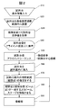
- 2 is a flowchart showing a flow from sample stage image alignment to sample observation by electron beam irradiation in the scanning electron microscope shown in FIG. 1. It is explanatory drawing of the sample base image alignment sequence which concerns on a 1st Example. It is explanatory drawing of the sample stand image alignment sequence which concerns on a 2nd Example. It is explanatory drawing of the sample stand image alignment sequence which concerns on a 3rd Example. It is explanatory drawing of the sample stand image alignment sequence which concerns on a 4th Example. It is explanatory drawing of the sample base image alignment sequence which concerns on a 5th Example.
- the charged particle beam apparatus will be described using a scanning electron microscope as an example.
- the charged particle beam apparatus of the present invention is not limited to the scanning electron microscope.
- the observation range on the sample from which the observation image is acquired by the charged particle beam device is set as the visual field range, while the charged particle beam
- the imaging magnification of the captured image used for setting the visual field range is charged.
- a scanning ion microscope for example, a scanning ion microscope, a scanning transmission electron microscope, a combined device of these and a sample processing device, or an analysis / inspection device applying these, etc. .
- FIG. 1 is a schematic configuration diagram of an example of a scanning electron microscope as a charged particle beam apparatus according to an embodiment of the present invention.
- the scanning electron microscope 1 shows a microscope apparatus body 2 in which a lens barrel 10 and a sample chamber housing 21 forming a sample chamber 20 are integrated, and exhausts the inside of the lens barrel 10 and the sample chamber 20. And a control device 30 for controlling each part of the microscope apparatus.
- the lens barrel 10 is provided with an electron gun 11 constituting a charged particle source that emits an electron beam 3 as a charged particle beam, and an electron optical system 12 as a charged particle optical system that controls irradiation of the electron beam 3. ing.
- an electron gun 11 constituting a charged particle source that emits an electron beam 3 as a charged particle beam
- an electron optical system 12 as a charged particle optical system that controls irradiation of the electron beam 3. ing.
- the inside of the lens barrel 10 is kept in a vacuum state by a vacuum evacuation means.
- the electron optical system 12 includes an anode 13 that accelerates the electron beam 3 emitted from the electron gun 11, a condenser lens 14 that focuses the electron beam 3, a deflector 15 that scans the electron beam 3, and an electron optical system 12. And an objective lens 16 for adjusting the focus of the electron beam 3 along the optical axis direction.
- a detector 17 that detects signal particles (for example, secondary electrons and reflected electrons) 4 generated from the sample 5 by irradiation of the electron beam 3 is also provided in the lens barrel 10. .
- the sample chamber 20 is configured to accommodate the sample stage 6 on which the sample 5 is placed through an open / close port (not shown) provided in the sample chamber casing 21 that can be opened and closed.
- the sample chamber 20 is provided with a stage 22 on which the sample stage 6 is held.
- the sample chamber 20 is kept in a vacuum state by evacuating the room atmosphere by vacuum evacuation means during sample observation.
- the stage 22 includes a mounted portion 23 to which the sample stage 6 is detachably attached, and the mounted portion 23 is moved, for example, in the horizontal plane and in the height direction, rotated, or tilted in the sample chamber 20.
- a moving mechanism 24 for displacing the position and orientation of the sample 5 in the sample chamber 20 together with the sample stage 6 is provided.
- the stage 22 holds the sample stage 6 in the sample chamber 20, displaces the sample 5 placed on the sample stage 6 together with the sample stage 6, and irradiates the sample 5 with the electron beam 3 from the electron optical system 12. And / or changing the irradiation direction.
- the sample table 6 is provided with a mounting surface 6A on which the sample 5 is mounted, and a mounting portion 6B for the mounted portions 23 and 44 respectively provided on the stage 22 and a mounting table 41 of the imaging device 40 described later. ing.
- the sample stage 6 views the placement surface 6A and / or the sample stage 6 itself along the axial direction of the sample stage 6 itself that is perpendicular to the placement surface 6A and passes through the center and / or the center of gravity of the placement surface 6A.
- the shape (hereinafter collectively referred to as the contour S of the sample stage 6) is configured in advance so as to have a predetermined shape.
- the sample stage 6 has a circular contour S.
- the outline S of the sample stage 6 is not limited to a circle. For example, by forming the outline S into a figure such as a rectangle, a parallelogram, and a regular polygon in addition to a circle, The center of gravity and the center of the contour S coincide with each other, and sample image alignment described later becomes easy.
- the electron beam 3 emitted from the electron gun 11 is controlled / accelerated by the anode 13, focused by the condenser lens 14 and the objective lens 16, and then the lens barrel 10.
- the electron beam 3 from the lens barrel 10 is deflected by the deflector 15, and the scanning range, scanning direction, and scanning speed of the electron beam 3 irradiated onto the sample 5 are adjusted.
- the signal particles 4 generated from the sample 5 by the irradiation of the electron beam 3 are detected by the detector 17.
- control device 30 includes a stage control unit 31, a signal processing unit 32, a device control unit 33, and a computer unit 34, and controls each unit of the device.
- the stage control unit 31 performs drive control of the moving mechanism 24 of the stage 22 in accordance with instructions relating to movement, rotation, and tilt of the mounted portion 23 to which the sample stage 6 is attached, which is supplied from the apparatus control unit 33.
- the signal processing unit 32 amplifies and A / D-converts the detection signal from the detector 17, stores it in the image memory in association with the irradiation position of the electron beam 3 controlled by the apparatus control unit 33, and irradiates the electron beam 3. Generate range image data.
- the apparatus control unit 33 controls the electron gun 11 and the electron optical system 12 according to the observation information of the sample 5 including alignment information by the sample table image alignment described later from the computer unit 34 and the visual field range, etc.
- the stage 22 on which the sample stage 6 on which the sample 5 is mounted is controlled via the stage control unit 31 to control the position and orientation of the sample 5 in the sample chamber 20. Take control. Further, the apparatus control unit 33 transfers the image data generated by the signal processing unit 32 to the computer unit 34 based on a transfer instruction from the computer unit 34.
- the computer unit 34 controls each part of the apparatus including the electron gun 11, the electron optical system 12, and the stage 22 via the apparatus control unit 33, and performs an alignment process including observation processing of the sample 5 and sample base image alignment described later. It controls the entire device.
- the computer unit 34 is for setting a computer main body 34A having a CPU, a memory, an interface and the like, an operation input device 34B such as a mouse, a keyboard, and an operation panel, and an observation condition and alignment of the sample 5 including a visual field range.
- a display device (display) 34C for displaying an observation image of the sample 5 created by the computer main body 34A based on the image data acquired from the device control unit 33. Yes.
- the computer unit 34 is also connected to the imaging device 40 for communication, so that an imaging image captured by the imaging device 40 can be directly acquired from the imaging device 40.
- the imaging device 40 is configured to be provided outside the sample chamber 20 of the scanning electron microscope 1 separately from the microscope apparatus body 2 of the scanning electron microscope 1.
- the imaging device 40 captures captured images of the sample stage 6 and the sample 5 that are used in the setting of the visual field range and alignment in the scanning electron microscope 1.
- the imaging device 40 is supported on a stand 42 erected from the mounting base 41 with the CCD camera 43 spaced apart from the mounting base 41 with the imaging direction directed toward the mounting base 41.
- the mounting table 41 is provided with a mounted portion 44 to which the mounting portion 6B of the sample table 6 is detachably mounted in a state where the mounting surface 6A of the sample table 6 is directed along the imaging direction.
- the mounting base 41 in the imaging device 40 is such that the mounted portion 44 matches the axial direction of the sample base 6 itself with the optical axis direction of the CCD camera 43 when the mounting portion 6B of the sample base 6 is installed. It is formed to be able to.
- the mounted portion 44 of the mounting base 41 has the same shape as the mounted portion 23 of the stage 22. Therefore, in the case of the illustrated imaging apparatus 40, the mounted portion 44 is replaceable with respect to the mounting base 41.
- the size and shape of the sample base 6 due to the difference in the model of the scanning electron microscope 1 or the like.
- the same imaging device 40 can be used for searching the field of view of another scanning electron microscope. Even if the mounted portion 44 of the mounting base 41 is dedicated to a predetermined scanning electron microscope 1 and the sample stage 6 that cannot be replaced, depending on the difference between the scanning electron microscope 1 and the sample stage 6. It may be provided with a mechanism capable of adjusting the mounting.
- the CCD camera 101 of the image pickup apparatus 40 picks up the image so that it can cope with the difference in the size of the sample 5 placed on the placement surface 6A of the sample stand 6 or the size of the sample stand 6 itself.
- the magnification can be adjusted arbitrarily. As a result, the user can appropriately magnify / reduce the optical image of the sample stage 6 on which the sample 5 is placed at an imaging magnification.
- the optical image of the sample stage 6 captured by the imaging apparatus 40 and the optical image of the sample stage 6 on which the sample 5 is placed are directly captured by the computer unit 34 of the scanning electron microscope 1 connected to the imaging apparatus 40 in communication. It can be acquired from the device 40.
- the computer unit 34 uses the GUI (Graphical) on the OSD screen for the acquired optical image of the sample stage 6 and the sample 5 when setting the sample stage image alignment and field range described later in searching the field of view of the scanning electron microscope 1.
- User Interface is displayed on the display device 34C.
- the CCD camera 43 is used as the imaging device of the imaging device 40.
- the imaging device may be a CMOS image sensor or an imaging device other than these optical imaging devices.
- the computer unit 34 of the scanning electron microscope 1 and the imaging device 40 are configured to be connected for communication, but the two are not connected.
- the user can connect the imaging device 40 via a storage medium. The captured image may be read and stored in the computer unit 34.
- the computer unit 34 of the scanning electron microscope 1 displays an optical image.
- the flow from sample table image alignment for recognizing the size and center position of the sample table to sample observation by irradiation of the electron beam 3 onto the sample 5 will be described with reference to FIG.
- FIG. 2 is a flowchart showing a flow from sample image alignment to sample observation by electron beam irradiation in a scanning electron microscope.
- Step S10 When observing the sample 5 with the scanning electron microscope 1, the user inputs information such as the actual sample stage size and shape of the sample stage 6 used for observing the sample 5 as basic information. The input is performed by the computer unit 34 of the scanning electron microscope 1 based on a predetermined operation of the operation input device 34B.
- Step S20 The user installs the sample table 6 used for observing the sample 5 on the mounting table 41 of the imaging device 40.
- the acquisition of the optical image of the sample table 6 used in the sample table image alignment and the acquisition of the optical image of the sample 5 used for setting the visual field range during the sample observation are performed once for the mounting table 41.
- a sample stage 6 on which a sample 5 to be observed with a scanning electron microscope is placed is also used for obtaining an optical image of the sample stage 6 used in the sample stage image alignment so that the stage 6 can be attached. Will be described.
- the installation is performed by attaching the attachment portion 6B of the sample stage 6 to the attachment portion 44 of the attachment base 41 provided in the imaging device 40.
- a mounting portion 44 having the same shape as the mounting portion 23 of the stage 22 is prepared in advance on the mounting base 41 of the imaging device 40.
- the sample table 6 has the mounting surface 6A of the sample table 6 installed on the mounting table 41 and the sample 5 opposed to the CCD camera 43, and the axial direction of the sample table 6 itself is the optical axis of the CCD camera 43. It is held at a predetermined imaging position of the imaging device 40 that matches the direction.
- the sample stage 6 can be automatically attached using, for example, a material handling device.
- Step S30 The user takes an optical image including the sample stage image of the entire sample stage 6 by the imaging device 40.
- the user When setting the observation range on the sample on which the observation image is acquired by the charged particle beam device as the visual field range on the optical image of the sample 5 acquired by the imaging device 40, the user usually uses the setting of the visual field range.
- the sample stage 6 is appropriately enlarged / reduced at an imaging magnification according to the size of the sample 5 placed on the sample stage 6 and imaged.
- step S30 since the size and center position of the sample 5 on the optical image used for setting the visual field range are unknown at that time, the user can see the entire sample stage 6 in the optical image captured by the imaging device 40.
- the sample 5 is imaged at an appropriate imaging magnification so as to fit.
- optical image in which the entire sample stage 6 is captured and the optical image of the sample 5 for setting the visual field range may be the same or different.
- optical image in which the entire sample stage 6 is accommodated is referred to as an optical image 61 including the sample stage image
- sample stage image 62 for convenience (see FIG. 3).
- Step S40 In the computer unit 34 of the scanning electron microscope 1, the computer main body 34A acquires the optical image 61 including the sample base image 62 from the imaging device 40.
- the computer main body 34A displays a sample table image alignment screen, which is an OSD screen of sample table image alignment, on the display device 34C, and the sample acquired from the imaging device 40 as a GUI (Graphical User Interface) on the alignment screen.
- An optical image 62 including a trapezoid image 62 is displayed.
- Step S50 In the computer unit 34 of the scanning electron microscope 1, the computer main body 34A performs a sample table image alignment sequence described later, and the sample table in the optical image 61 including the sample table image 62 obtained from the imaging device 40. Recognizing the size (size) and center coordinates of the image 62 and collating with the known basic information of the sample stage 6 given in step S10, the optical image 61 including the acquired sample stage image 62 is captured. Calculate the magnification.
- each origin coordinate (for example, each visual field center position) of the scanning electron microscope 1 and the imaging device 40 is arranged on an arbitrary stage coordinate related to the movement of the mounted portion 23 of the stage 22 and the like. If the center of the optical image 61 picked up by the device 40 is displayed so as to be the center of the display device 34C on which the observation image acquired by the scanning electron microscope 1 is displayed, it is possible to align the center coordinates of each other. .
- the stage 22 normally moves the sample 5 together with the sample stage 6 with reference to the center of the attached part 23, that is, the sample stage 6 attached to the attached part 23 in the sample chamber 20.
- the center of the sample base 6 attached to the attachment portion 44 of the attachment base 41 aligned with the optical axis of the CCD camera 43 in the imaging device 40 and the same attached to the attachment portion 23 in the scanning electron microscope 1.
- the alignment of the scanning electron microscope 1 becomes easy.
- the center of each of the observation image and the optical image is slightly between the scanning electron microscope 1 that obtains the observation image of the sample 5 and the imaging device 40 that obtains the optical image of the sample 5 for setting the visual field range. It may shift. Therefore, the visual field range is set by recognizing the size and center coordinates of the sample image 62 in the optical image 61 including the sample image 62 and calculating the imaging magnification of the optical image 61 including the sample image 62. Therefore, alignment between the optical image 61 acquired from the imaging device 40 and the scanning electron microscope 1 that acquires the observed image can be performed.
- Step S60 The user attaches the mounting portion 6B of the sample stage 6 to the mounted portion 23 of the stage 22 and introduces the sample stage 6 to the electron microscope observation position in the sample chamber 20.
- the introduction of the sample stage 6 to the electron microscope observation position in the sample chamber 20 can also be automatically performed.
- Step S70 The user sets an optical image 61 of the sample 5 by the imaging device 40 in order to set an arbitrary observation point or observation range on the sample 5 where the observation image is acquired by irradiating the electron beam 3 as the visual field range.
- An OSD screen for sample observation included as a GUI is displayed on the display device 34 ⁇ / b> C of the computer unit 34.
- the user designates an observation point or an observation image for obtaining an observation image by irradiating the electron beam 3 on the optical image 61 of the sample 5 included as a GUI on the sample observation screen, and scans the electron.
- the visual field range by the microscope 1 is set.
- the designation and setting are performed by the computer main body 34A of the computer unit 34 based on the operation input from the operation input device 34B.
- Step S80 In the computer unit 34 of the scanning electron microscope 1, the sample on the optical image of the sample 5 included as the GUI in the sample observation screen recognized by the computer main body 34A in the sample base image alignment in Step S50 Based on the size and center coordinates of the trapezoid 62 and the imaging magnification of the sample trapezoid 62, control information for each part of the apparatus instructed to the apparatus controller 33 is generated to acquire an observation image in the visual field range set in step S70. .
- the device control unit 33 controls the movement of the mounted portion 23 of the stage 17 by the moving mechanism 24 based on the control information of each part of the device, or controls the optical axis of the electron beam 3 in step S70.
- the field-of-view range on the sample 5 set and input in step S1 is made to coincide with the observation range on the sample 5 to which the electron beam 3 is actually irradiated, and the field-of-view range on the sample 5 is irradiated with the electron beam 3.
- Step S90 In the computer unit 34 of the scanning electron microscope 1, the computer main body 34A is set and inputted in step S70 based on the image data generated by the signal processing unit 32 transferred via the device control unit 33. Then, an observation image of the sample 5 whose observation range is the viewing field range on the sample 5 is created and displayed on the observation screen of the display device 34C.
- the sample image described in step S50 using the optical image 61 including the sample image 62 displayed on the sample image alignment screen in step S40 and the optical image 61 including the sample image 62 is used.
- An alignment sequence will be described based on an embodiment.
- the sample stage image alignment it is necessary to match the center of the sample stage 6 when accommodated in the sample chamber 20 with the center of the sample stage 6 on the optical image of the sample 5 for setting the visual field range.
- the size and center coordinates of the sample image 62 on the optical image 61 are recognized from the optical image 61 including the sample image 62 captured by the image capturing apparatus 40 at an appropriate imaging magnification, and the size is appropriately determined.
- the imaging magnification of is calculated.
- FIG. 3 is an explanatory diagram of the sample base image alignment sequence according to the first embodiment.
- the size and center coordinates of the sample table image 62 are recognized on the optical image including the sample table image 62 of the sample table 6 having the circular contour S, and the imaging magnification of the optical image 61 is calculated.
- the alignment sequence to perform is shown typically.
- an optical image 61 including a sample table image 62 acquired from the imaging device 40 as a GUI is displayed on a predetermined screen portion on the sample table image alignment screen displayed on the display device 34C. Is displayed in such a manner that the portion of the sample image 62 appears.
- the display of the sample image 62 is a sample image 62 in the optical image 61 when the optical image 61 including the sample image 62 acquired from the imaging device 40 is enlarged / reduced at a known display magnification.
- the display of the part containing a part may be sufficient.
- the display magnification is the same magnification, and on the GUI screen 60 formed of the predetermined screen portion, the entire optical image 61 including the sample base image 62 is displayed, and the GUI screen 60 is displayed as the optical image.
- the entire number 61 corresponds.
- the GUI screen 60 includes three known linear guide lines 65 (with different inclinations viewed on the coordinates of the optical image 61, that is, on the pixel coordinates of the CCD camera 43 of the imaging device 40. 65-1, 65-2, 65-3) are superimposed and displayed as shown in FIG. Therefore, if these three straight guide lines 65-1, 65-2, 65-3 are appropriately translated on the GUI screen 60, the intersection 67 (67- A plurality of similar triangles 68 having vertices at 1,67-2, 67-3) can be formed on the GUI screen 60, that is, on the optical image 61.
- Each of the three straight guide lines 65-1, 65-2, 65-3 on the GUI screen 60 selects a desired straight guide line 65 by a predetermined operation of the operation input device 34B of the computer unit 34 by the user.
- the GUI screen 60 that is, on the optical image 61, it can be translated from the current position by a desired amount.
- the user operates the operation input device 34B on the GUI screen 60 in the sample table alignment screen, and first, three straight guide lines 65-1, 65-2, 65-. 3 is selected and translated on the GUI screen 60, that is, on the optical image 61, as shown in FIG. 3B.
- the straight guide line 65-1 is moved and adjusted on the GUI screen 60, that is, on the optical image 61 so as to come into contact with the sample table image 62.
- the user selects each of the remaining two straight guide lines 65-2 and 65-3 one by one in the same manner, and translates them on the GUI screen 60, that is, on the optical image 61.
- the linear guide lines 65-2 and 65-3 are moved and adjusted on the GUI screen 60, that is, on the optical image 61 so as to be in contact with the sample base image 62.
- each straight guide line 65 (65-1, 65-2, 65-3) On the GUI screen 60 and the optical image 61, on each straight guide line 65 (65-1, 65-2, 65-3), a contact 66 (66-1, 66-2, 66-) with the contour S is provided. 3) is provided.
- Each straight guide line 65 (65-1, 65-2, 65-3) is connected to the circular contour S of the sample image 62 at a contact 66 (66-1, 66-2, 66-3).
- Each side of the circumscribed triangle 68 is formed.
- the user displays the triangle 68 circumscribing the circular contour S of the sample image 62 using the linear guide lines 65 (65-1, 65-2, 65-3), the GUI screen 60 and the optical system.
- the operation input device 34B is operated to recognize the size and center position of the sample image 62 on the optical image 61 of the sample image 62 having the circular outline S, and the optical image.
- the calculation of the imaging magnification of 61 is instructed to the computer main body 34A of the computer unit 34.
- the computer main body 34A Upon receipt of this instruction, the computer main body 34A is the initial state of each of the three known linear guide lines 65 (65-1, 65-2, 65-3) having different inclinations as viewed on the coordinates of the optical image 61. Based on the function expression, the three linear guide lines 65 (65-1, 65-2, 65-3) by the user based on the parallel movement results on the coordinates of the optical image 61, the three after the movement adjustment. A functional expression of the straight guide line 65 (65-1, 65-2, 65-3) is calculated. Thereafter, the computer main body 34A displays the optical image 61 of the two linear guide lines having different combinations among the three linear guide lines 65 (65-1, 65-2, 65-3) after the movement adjustment.
- the computer main body 34A recognizes the size and the center position of the sample image 62 on the optical image 61 based on the coordinates of each vertex as the measurement reference points.
- the center position of the sample base image 62 on the optical image 61 is a triangle without being directly recognized by the complicated and troublesome automatic image analysis about the contour S of the sample base image 62 on the optical image 61.
- the size of the sample image 62 on the optical image 61 can be easily and uniquely obtained if the center position of the sample image 62 is defined, so that the diameter of the circular contour S can be easily and uniquely obtained. Can be calculated.
- the computer main body 34A is obtained from the imaging device 40 from the size of the sample table 62 on the optical image 61 and basic information such as the actual sample table size and shape input in advance in step S10 of FIG.
- the imaging magnification of the optical image 61 including the sample base image 62 is calculated.
- the three linear guide lines 65 (65-1, 65-2, 65-3) are moved and adjusted, and the sample table is thus adjusted.
- the coordinates of each vertex of the triangle 68 circumscribing the image 62 are converted into two linear guides of different combinations in the three linear guide lines 65 (65-1, 65-2, 65-3) after movement adjustment.
- Intersection 67 (67-1, 67-2, 67-3) that can be determined at the intersection 67 (67-1, 67-2, 67-3) of the lines and becomes each vertex of the triangle 68 as a measurement reference point From the respective coordinates, the size and center position of the sample table image 62 on the optical image 61 and the imaging magnification of the optical image 61 including the sample table image 62 are automatically acquired with high accuracy and with a simple calculation. be able to.
- the vertex (intersection point) 67 (67-1, 67-2, 67-3) of the triangle 68 is a measurement reference point, the user can determine the exact position of the straight line 65 (65-1, 65-2, 65-3)
- the generation of the contact 66 (66-1, 66-2, 66-3) with respect to the contour S of the sample image 62 is confirmed by the contact display as shown in FIG. it can.
- the three straight guide lines 65 are points that substantially divide the circular outline S of the sample image 62 as shown in FIG.
- the outer contact 66 (66-1, 66-2, 66-3) that substantially divides the circular contour S along the length thereof is a reference for acquiring the measurement reference point. Therefore, it is possible to obtain a higher accuracy imaging magnification.
- the three straight guide lines 65 are individually contacted with the sample image 62 on the GUI screen 60, that is, on the optical image 61.
- the configuration is such that the movement is adjusted, the two straight guide lines 65 (65-1, 65-2) among the three straight guide lines 65 (65-1, 65-2, 65-3) are previously set in the GUI. It is displayed on the screen 60 so as to be able to translate in an integrated manner, and a guide line pair consisting of these two straight guide lines 65 (65-1, 65-2) and the remaining one straight guide line 65. (65-3) may be individually adjusted so as to be in contact with the sample base image 62 on the GUI screen 60, that is, on the optical image 61.
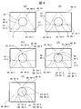
- FIG. 4 is an explanatory diagram of a sample base image alignment sequence according to the second embodiment.
- the three linear guide lines 65 (65-1, 65-2, 65-3) are moved and adjusted to circumscribe the sample base image 62 serving as a measurement reference point.
- the coordinates of the vertices of the triangle 68 to be moved are the intersections of two linear guide lines of different combinations in the three linear guide lines 65 (65-1, 65-2, 65-3) after movement adjustment. It was set as the structure decided by.
- the coordinates of the vertices of the triangle 68 inscribed in the sample image 62 are adjusted by moving and adjusting the three straight guide lines 65 (65-1, 65-2, 65-3). Is determined at the intersection of two linear guide lines of different combinations in the three linear guide lines 65 (65-1, 65-2, 65-3) after movement adjustment. It was.
- the first GUI screen 60 shown in FIG. 4A before the movement adjustment of the three straight guide lines 65 (65-1, 65-2, 65-3) is the first This is the same as the initial GUI screen 60 shown in FIG.
- the user operates the operation input device 34B on the GUI screen 60 in the sample table alignment screen, selects, for example, the straight guide line 65-1, and displays the GUI screen 60. That is, the linear guide line 65-is translated on the optical image 61 and intersects the contour S of the sample table image 62 at two intersections 66-1 and 66-3 as shown in FIG. 1 is moved and adjusted on the GUI screen 60, that is, on the optical image 61.
- the user selects each of the remaining two straight guide lines 65-2 and 65-3 one by one in the same manner, and translates them on the GUI screen 60, that is, on the optical image 61.
- the straight guide lines 65-2 and 65-3 are respectively located on the two intersections 66-1 and 66-3 defined by the straight guide line 65-1. The movement is adjusted so as to cross each of the straight guide lines 65-1.
- intersections 67 (67-1, 66-2, 67-3) of the three straight guide lines 65 (65-1, 65-2, 65-3) are similarly defined.
- FIG. 4D when the intersection point 66-2 of the remaining two straight guide lines 65-2 and 65-3 is not located on the contour S of the sample image 62 ( In other words, apart from the intersection point 67-2, there are intersection points 66-2 and 66-2 with the contour S of the sample image 62 of the remaining two straight guide lines 65-2 and 65-3. 3), the three intersections 67 (67-1, 67-2, 67-3) are not treated as measurement reference points. In such a case, as shown in FIG.
- the coordinates of the vertices of the triangle 68 inscribed in the sample image 62 are set to the three straight guide lines 65 (65-1, 65-2, 65 after the final movement adjustment). -3) can be determined at the intersection 67 (67-1, 67-2, 67-3) of two linear guide lines of different combinations. Then, the center position of the sample image 62 on the optical image 61 is determined based on the measurement reference without directly recognizing the complicated and troublesome automatic image analysis of the contour S of the sample image 62 on the optical image 61.
- the optical image 61 is automatically calculated by simple calculation.
- the size and center position of the sample stage image 62 and the imaging magnification of the optical image 61 including the sample stage image 62 can be acquired with high accuracy and speed.
- intersection point 67 (67-1, 67-2, 67-3) of the triangle 68 is a measurement reference point
- the user can determine the exact position of the straight line 65 (65-1, 65-2, 65-3)
- the coincidence of the respective intersection points 66 (66-1, 66-2, 66-3) with the contour S of the sample image 62 is represented by the intersection point 66 as shown in FIG. It can be confirmed by disappearance.
- the three straight guide lines 65 are points that substantially divide the circular outline S of the sample image 62 as shown in FIG.
- the outer contact 66 (66-1, 66-2, 66-3) that substantially divides the circular contour S along the length thereof is a reference for acquiring the measurement reference point. Therefore, it is possible to obtain a higher accuracy imaging magnification.
- FIG. 5 is an explanatory diagram of a sample base image alignment sequence according to the third embodiment.
- the contact point or intersection point 66 is designated by three straight guide lines 65 (65-1, 65-2, 65-3). Obviously, it can be specified.
- straight guide lines 65 (65-1, 65-2, 65-3, 65-4) parallel to the respective sides of the regular polygon 69 having four or more sides are displayed on the GUI screen 60. Then, each linear guide line 65 is moved and adjusted, and each vertex 67 of the regular polygon 69 circumscribing the sample image 62 is set as a measurement reference point.
- straight guide lines 65 (65-1, 65-2, 65-3, 65-4) parallel to the respective sides of a square (regular polygon) 69 are displayed on the GUI screen 60.
- each vertex 67 of the square 69 circumscribing the sample image 62 is used as a measurement reference point.
- An example of setting is shown.
- the coordinates of each vertex of a regular polygon (square in the case of FIG. 5) 69 circumscribing the sample image 62 are converted into a plurality of linear guide lines 65 (in the case of FIG. 5) after the movement adjustment. Then, it is determined at the intersection 67 (four in the case of FIG. 5, 67-1 to 67-4) of two linear guide lines of different combinations among the four of 65-1 to 65-4). can do. Then, the center position of the sample image 62 on the optical image 61 is a regular number without direct recognition by the complicated and troublesome automatic image analysis about the contour S of the sample image 62 on the optical image 61.
- the coordinates of the intersections 67 (four in the case of FIG.
- 67-1 to 67-4) that are the vertices of the square (in the case of FIG. 5) 69 are set as the measurement reference points, and the center ( In the case of FIG. 5, the size and center position of the sample image 62 on the optical image 61 and the image of the optical image 61 including the sample image 62 are automatically obtained by calculating the inner center).
- the magnification can be acquired with high accuracy and speed.
- it can respond also to sample stands, such as an ellipse.
- FIG. 6 is an explanatory diagram of a sample base image alignment sequence according to the fourth embodiment.
- the contour S of the sample base image 62 on the optical image 61 is rectangular.
- the coordinates of the vertices of the rectangle 69 matching the sample table 62 are used as measurement reference points, and a plurality of linear guide lines 65 after movement adjustment are performed. It can be determined at the intersection 67 (67-1 to 67-4) of two linear guide lines of different combinations in (65-1 to 65-4). Then, the center position of the sample table 62 on the optical image 61 is not directly recognized by the complicated and troublesome automatic image analysis on the contour S of the sample table 62 on the optical image 61. By calculating the center (the center of gravity in the case of FIG. 6) of the intersections 67 (four in the case of FIG. 6) of the intersections 67 (four in the case of FIG. ).
- the size and center position of the sample base image 62 on the optical image 61 and the imaging magnification of the optical image 61 including the sample base image 62 can be acquired with high accuracy and speed automatically by simple calculation.
- the present embodiment can be obtained with high accuracy and speed especially for a rectangular sample stage.
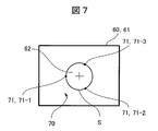
- FIG. 7 is an explanatory diagram of a sample base image alignment sequence according to the fifth embodiment.
- the straight guide lines 65 used in these embodiments are not used, and instead of the straight guide lines 65 on the initial GUI screen 60, A pointer 70 that can be moved on the GUI screen 60 by operating the operation input device 34B is displayed.
- an optical image 61 including a sample base image having a contour S such as a circle, rectangle, parallelogram, or regular polygon.
- the pointer 70 is moved point by point on the GUI screen 60.
- the pointer 70 is moved point by point on the GUI screen 60.
- at least three points 71 (71-1, 71-2, 71-3) on the contour are set as measurement reference points as shown in FIG.
- a triangle inscribed in the sample table image 62 having the circular outline S can be defined on the GUI screen 60.
- the sample stand image 62 as a measurement reference point is not directly recognized by the complicated and troublesome automatic image analysis about the contour S of the sample stand image 62 on the optical image 61.
- the optical image 61 is automatically calculated by simple calculation. The size and center position of the sample table image 62 and the imaging magnification of the optical image 61 including the sample table image 62 can be quickly acquired with a small number of man-hours.
- FIG. 8 is an explanatory diagram of a sample base image alignment sequence according to the sixth embodiment.
- the diameter and the diagonal line are first designated as a start point 71 by the pointer 70 at an arbitrary point on the contour of the optical image 61 including the sample image 62, and the start point.
- the end point 72 of the line segment 73 extending from 71 is dragged and dropped from the start point 71 to another arbitrary point on the contour of the sample stage image 62, and the end point 72 of the line segment 73 is then moved to the sample stage. It is set on the optical image 61 including the image.
- the line segment 73 is dragged on the optical image 61 and displayed on the optical image 61 including the sample table image. Accordingly, by dragging and dropping the line segment 73 while confirming the straight guide line 65, the diameter and the diagonal line related to the contour S of the sample image 62 are displayed on the optical image 61 as shown in FIG.
- the imaging magnification can be quickly increased with less man-hours. You can get it.
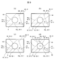
- FIG. 9 is an explanatory diagram of a sample base image alignment sequence according to the seventh embodiment.
- the coordinates of the vertices of the triangle 68 circumscribing or inscribed in the sample image 62, which serve as measurement reference points, are converted into three linear guide lines 65 after movement adjustment.
- three linear guide lines 65 (65-1, 65-2) are determined.
- 65-3) In the present embodiment, each of the three straight guide lines 65 (65-1, 65-2, 65-3) is moved in parallel.
- Two types of linear guide lines composed of parallel movement linear guide lines 65p (65-1, 65-3) for movement adjustment and tilt displacement linear guide lines 65r (65-2) for movement adjustment by tilting (rotating) displacement. It was composed of 65p and 65r.
- the initial GUI screen 60 shown in FIG. 9A before the movement adjustment of the three straight guide lines 65-1, 65-2, 65-3 is the same as that of the first embodiment. This is the same as the initial GUI screen 60 shown in FIG.
- the user operates the operation input device 34B on the GUI screen 60 in the sample image alignment screen, and selects, for example, the parallel movement straight guide line 65-1 (65p). Then, the image is translated on the GUI screen 60, that is, on the optical image 61, and is brought into contact with the contour S of the sample image 62 at the contact 66-1, as shown in FIG. 9B. 61 adjust the movement.
- the user selects the remaining one translational straight guide line 65-3 (65p) in the same manner, translates it on the GUI screen 60, that is, on the optical image 61, and FIG. As shown in (), the movement is adjusted on the GUI screen 60, that is, on the optical image 61 so as to contact the contour S of the sample image 62 at the contact 66-3.
- the user selects the remaining one tilt displacement linear guide line 65-2 (65r) and tilts (rotates) it on the GUI screen 60, that is, on the optical image 61, so that FIG. As shown in d), the movement is adjusted on the GUI screen 60, that is, on the optical image 61 so as to be in contact with the contour S of the sample image 62 at the contact 66-2.
- the tilt (rotation) displacement of the tilt displacement linear guide line 65-2 (65r) is brought into contact with the tilt displacement linear guide line 65-2 (65r) and the contour S of the sample image 62 with the contact 66-1 or 66-. 3 at the intersection 67-1 or 67-3 (not shown in FIG. 9C) with the translational linear guide line 65-1 (65p) or 65-1 (65p) adjusted to be in contact with 3
- One of the above is performed as a central point.
- the configuration is performed with the intersection point 67-1 as the center point, but the configuration may be performed with the intersection point 67-3 as the center point.
- the user may select either the selected intersection point 67-1 or 67-3 and set it as the center point.
- the tilt displacement linear guide line 65-2 (65r) can be tilted (rotated) by directly tilting (rotating) the tilt displacement linear guide line 65-2 or defining the center point. This is done by setting and inputting the value of the intersection angle ⁇ between the tilt displacement linear guide line 65-2 (65r) and the translational linear guide line 65-1 (65p) or 65-1 (65p).
- the coordinates of the vertices of the triangle 68 circumscribing the sample image 62 are set as the measurement reference points of the three straight guide lines 65 (65-1, 65-2, 65-3) after the final movement adjustment. It can be determined at an intersection 67 (67-1, 67-2, 67-3) between two linear guide lines of different combinations. Then, the center position of the sample image 62 on the optical image 61 is determined based on the measurement reference without directly recognizing the complicated and troublesome automatic image analysis of the contour S of the sample image 62 on the optical image 61.
- the optical image 61 is automatically calculated by simple calculation.
- the size and center position of the sample table image 62 and the imaging magnification of the optical image 61 including the sample table image 62 can be acquired with high accuracy and speed.
- the vertex (intersection point) 67 (67-1, 67-2, 67-3) of the triangle 68 is a measurement reference point, the user can determine the exact position of the straight line 65 (65-1, 65-2, 65-3)
- the generation of the contact 66 (66-1, 66-2, 66-3) with respect to the contour S of the sample image 62 is confirmed by the contact display as shown in FIG. it can.
- the translational straight guide lines 65-1 (65p) and 65-3 (65p) are moved and adjusted so as to be in contact with the contour S of the sample image 62 at the contacts 66-1 and 66-3, respectively.
- the procedure for moving and adjusting the tilt displacement linear guide line 65-2 (65r) has been described.
- the parallel movement linear guide line 65-1 (65p) is converted into the sample image 62.
- the tilt displacement linear guide line 65-2 (65r) is then moved and adjusted, and then the parallel moving linear guide line 65-3 (65p) is moved. Even if the adjustment is made, it is possible to obtain a state in which the straight guide lines 65-1 to 65-3 are in contact with the contour S of the sample image 62 at the contacts 66-1 to 66-3, respectively, as shown in FIG. it can.
- FIG. 10 and 11 are explanatory diagrams of modified examples of the sample base image alignment sequence according to the seventh embodiment shown in FIG.
- the parallel linear guide lines 65p (65-1, 65-3) that move and adjust the three linear guide lines 65 (65-1, 65-2, 65-3) are translated.
- 65-3) and two types of linear guide lines 65p and 65r composed of a tilt displacement linear guide line 65r (65-2) that moves and adjusts by tilt (rotation) displacement are shown in FIG.
- three linear guide lines 65 (65-1, 65-2, 65-3) are constituted by two types of linear guide lines 65p, 65r.
- 9 is the same as the seventh embodiment shown in FIG. 9 except that a translational linear guide line 65p (65-1) that translates and adjusts movement and a tilt displacement linear guideline that adjusts movement by tilting (rotating) displacement.
- 65r (65-2, 65-3) differs in the number of components of each of the two types of linear guide lines 65p, 65r.
- the tilt (rotation) displacement of the tilt displacement linear guide line 65r is automatically set with the intersection point with the predetermined parallel movement linear guide line 65p as the center point at the time of tilt (rotation) displacement.
- the center point can be moved to a desired point on a predetermined parallel movement straight guide line 65p by a predetermined operation by the user.
- the triangle 68 defined by each of the linear guide lines 65-1 to 65-3 adjusted for movement is inscribed in the contour S of the sample image 62. Even if it is a sample stand image alignment sequence, it is applicable, and the inscribed triangle is inferior to the case where the three linear guide lines 65 (65-1, 65-2, 65-3) are constituted by parallel translation linear guide lines 65p. 68 vertices (intersection points) 67 (67-1, 67-2, 67-3) can be obtained by an easy operation.
- the scanning electron microscope 1 according to the present embodiment is configured, but the charged particle beam apparatus according to the embodiment of the present invention is not limited to this, and includes modifications of various embodiments. It is.
- FIG. 12 is a schematic configuration diagram of another example of a scanning electron microscope as a charged particle beam apparatus according to another embodiment of the present invention.
- the imaging device 40 is configured to be provided outside the sample chamber 20 of the scanning electron microscope 1 separately from the microscope apparatus body 2.
- the imaging device 40 faces the imaging surface side of the CCD camera 43 into the sample chamber 20 and faces the microscope device body 2.
- the configuration is provided integrally. Accordingly, in the scanning electron microscope 1 ′, in the sample chamber 20, for example, the observation position where the electron beam 3 from the lens barrel 10 is irradiated and the imaging device 40 by the CCD camera 43 of the imaging device 40 are arranged on the sample stage.
- the optical axis direction of the electron optical system 12 and the imaging direction of the CCD camera 43 are set so that the moving position in the horizontal plane of the mounted portion 23 of the stage 22 to which the stage 6 is detachably attached is the same.
- the imaging device 40 is provided in the sample chamber housing 21 or the stage 22 is irradiated with the electron beam 3 so as to be able to cross on the mounting surface 6A of the sample stage 6 attached to the attached portion 23.
- the attachment portion 23 can be moved and displaced between the observation position and the image pickup position by the CCD camera 43.
- the openable / closable inlet / outlet of the sample 5 provided in the sample chamber casing 21 is provided between the acquisition of the captured image and the acquisition of the observation image.
- the observation image relating to the set visual field range can be continuously acquired in the sample chamber 21 as it is.
- the GUI screen 60 does not initially display the linear guide lines 65, but instead displays the sample
- a plurality of different straight guide line 65 icons are displayed in a selectable manner on the image alignment screen, and each time the user selects a desired straight guide line 65 icon, it corresponds to the icon selected on the GUI screen 60. It is also possible to adopt a configuration in which the straight line guide 65 is displayed.
- the icon corresponding to each of the two is provided, and the icon of the desired type of straight guide line 65-x used by the user is selected in accordance with the contour S of the sample image 62 in the optical image 61. It is also possible to adopt a configuration to do so.
- the number of icons, that is, the types of the straight guide lines 65 is not limited to the straight guide lines 65 shown in the first to fourth embodiments. You may make it provide.
- the linear guide 65 itself may be a polygonal line shape formed by integrating a plurality of linear guide lines 65 described in the third embodiment with reference to FIG. It is not limited to.
- the configuration of the charged particle beam apparatus according to the present invention is not limited to the above-described embodiments, and includes various modifications.
- the specific configurations in the above-described embodiments are for understanding the present invention, and are not necessarily limited to those provided with all the specific configurations described.
- a part of a specific configuration of one embodiment can be replaced with a specific configuration of another embodiment, and a specific configuration of one embodiment can be replaced with a specific configuration of another embodiment.
- each of the above-described configurations, functions, processing units, processing means, and the like may be realized by hardware by designing a part or all of them with, for example, an integrated circuit.
- each of the above-described configurations, functions, and the like may be realized by software obtained by the computer interpreting and executing a program that realizes each function.
- Information such as programs, tables, and files for realizing each function can be stored in a memory, a hard disk, an SSD (Solid State Drive), or a recording medium such as an IC card, an SD card, or a DVD.
Landscapes
- Chemical & Material Sciences (AREA)
- Analytical Chemistry (AREA)
- Analysing Materials By The Use Of Radiation (AREA)
Abstract
Description
図3は、第1の実施例に係る試料台像アライメントシーケンスの説明図である。
図4は、第2の実施例に係る試料台像アライメントシーケンスの説明図である。
図5は、第3の実施例に係る試料台像アライメントシーケンスの説明図である。
図6は、第4の実施例に係る試料台像アライメントシーケンスの説明図である。
図7は、第5の実施例に係る試料台像アライメントシーケンスの説明図である。
図8は、第6の実施例に係る試料台像アライメントシーケンスの説明図である。
図9は、第7の実施例に係る試料台像アライメントシーケンスの説明図である。
4 信号粒子、 5 試料、 6 試料台、 6A 載置面、
6B 取付部、 S 輪郭形状、 10 鏡筒、 11 電子銃、
12 電子光学系、 13 アノード、 14 コンデンサレンズ、
15 偏向器、 16 対物レンズ、 17 検出器、
20 試料室、 21 試料室筐体、 22 ステージ、
23 被取付部、 24 移動機構、 30 制御装置、
31 ステージ制御部、 32 信号処理部、 33 装置制御部、
34 コンピュータ部、 34A コンピュータ本体、
34B 操作入力機器、 34C 表示装置、 40 撮像装置、
41 取付台、 42 スタンド、 43 CCDカメラ、
44 被取付部、 60 GUI画面、 61 試料台像を含む光学像、
62 試料台像、 65 直線ガイド線、 66 接点、
67 交点、 68 三角形、 69 正方形(正多角形)、
70 ポインタ、 71 始点、 72 終点、
73 線分、
Claims (15)
- 荷電粒子線を放出する荷電粒子源と、
前記荷電粒子源からの荷電粒子線を試料に照射する荷電粒子光学系と、
試料が載置された試料台が収容される試料室と、
前記試料室内で前記試料台を保持するとともに、試料に対する前記荷電粒子光学系からの荷電粒子線の照射位置及び/又は照射方向を変化させるために、前記試料室内で試料を前記試料台ごと動かすステージと、
荷電粒子線の照射により前記試料台に載置された試料から発生する信号粒子を検出する検出器と、
前記検出器によって検出された信号粒子を基に、荷電粒子線が照射された試料上の観察範囲の観察像を生成する画像処理部と
を備えた荷電粒子線装置であって、
撮像装置によって取得された前記試料台の試料台像を含む撮像画像を表示する画像表示部と、
前記画像表示部に表示された撮像画像上において、試料台像の輪郭上の互いに離間して位置する点を指定することにより、測定基準ポイントを設定入力する操作入力部と、
前記操作入力部の操作で設定入力された複数の測定基準ポイント間の撮像画像上の距離に基づいて、当該撮像画像上における試料台像の大きさを演算する試料台像大きさ演算部と、
前記試料台像大きさ演算部によって算出された試料台像の大きさと、前記試料台の実際の大きさとから、当該撮像画像の撮像倍率を演算する撮像倍率演算部と
を備えることを特徴とする荷電粒子線装置。 - 請求項1に記載の荷電粒子線装置において、
試料が載置された前記試料台の、前記撮像倍率演算部で算出された撮像倍率と同倍率で取得された撮像画像上で、前記荷電粒子線を照射して観察像を取得する当該試料上の観察範囲を視野範囲として設定し、当該視野範囲に該当する試料上の観察範囲の観察像を取得する際、前記撮像倍率演算部で算出された撮像倍率を、荷電粒子線の照射位置に係る前記荷電粒子光学系及び/又は前記ステージのアライメントで使用する
ことを特徴とする荷電粒子線装置。 - 請求項1に記載の荷電粒子線装置において、
前記操作入力部の操作で設定入力される複数の測定基準ポイントは、前記画像表示部に表示された撮像画像中の試料台像の輪郭に外接若しくは内接する多角形の、それぞれ頂点になる
ことを特徴とする荷電粒子線装置。 - 請求項1に記載の荷電粒子線装置において、
測定基準ポイントは、前記画像表示部に撮像画像とともに表示され、互いの伸長方向が異なる複数の直線ガイド線を、前記操作入力部の操作に対応させて前記画像表示部の表示画面上でそれぞれ移動し、各直線ガイド線と撮像画像中の試料台像の輪郭との接点、又は互いの組み合わせが異なる2つの直線ガイド線と撮像画像中の試料台像の輪郭との交点を指定することによって設定入力される
ことを特徴とする荷電粒子線装置。 - 請求項4に記載の荷電粒子線装置において、
互いの伸長方向が異なる前記複数の直線ガイド線が、前記画像表示部の表示画面上で平行移動可能な複数の平行移動直線ガイド線である、又は、前記画像表示部の表示画面上で平行移動可能な少なくとも1つの平行移動直線ガイド線と前記画像表示部の表示画面上で傾倒変位可能な残りの傾倒変位直線ガイド線との組み合わせである
ことを特徴とする荷電粒子線装置。 - 請求項1に記載の荷電粒子線装置において、
測定基準ポイントは、試料台像を含む撮像画像が表示された前記画像表示部の表示画面上で、試料台像の輪郭上に前記操作入力部の操作により直接プロットすることによって設定入力される
ことを特徴とする荷電粒子線装置。 - 請求項6に記載の荷電粒子線装置において、
試料台像を含む撮像画像が表示された前記画像表示部の表示画面上には、既に設定入力された測定基準ポイントが表示され、一対の測定基準ポイントが設定されると、当該一対の測定基準ポイント間を結ぶ直線を斜辺又は対角線とする直角三角形又は長方形の残りの頂点がガイド表示される
ことを特徴とする荷電粒子線装置。 - 撮像装置によって取得された試料の撮像画像上で、荷電粒子線装置によって観察像を取得する当該試料上の観察範囲を視野範囲として設定する視野範囲設定ステップ、
前記荷電粒子線装置によって当該視野範囲に該当する試料上の観察範囲に荷電粒子線を照射して試料の観察像を取得する際、当該視野範囲の設定に用いられた撮像画像の前記撮像装置による撮像倍率を、荷電粒子線の照射位置のアライメントで使用するアライメントステップ
を含む荷電粒子線装置のアライメント方法であって、さらに、
前記撮像装置によって取得された、試料を載置する試料台の試料台像を含む撮像画像を、画像表示部に表示する試料台像表示ステップ、
前記試料台像表示ステップにより前記画像表示部に表示された撮像画像上において、試料台像の輪郭上の互いに離間して位置する点を操作入力部の操作に基づいて指定することにより、測定基準ポイントを設定入力する操作設定ステップ、
前記操作設定ステップにより設定入力された複数の測定基準ポイント間の撮像画像上の距離に基づいて、当該撮像画像上における試料台像の大きさを演算する試料台像大きさ演算ステップ、
前記試料台像大きさ演算ステップによって算出された試料台像の大きさと、前記試料台の実際の大きさとから、当該撮像画像の撮像倍率を演算する撮像倍率演算ステップ
を含むことを特徴とする荷電粒子線装置のアライメント方法。 - 請求項8に記載の荷電粒子線装置のアライメント方法において、
前記操作設定ステップでは、前記操作入力部の操作で設定入力される複数の測定基準ポイントは、前記画像表示部に表示された撮像画像中の試料台像の輪郭に外接若しくは内接する多角形の、それぞれ頂点になる
ことを特徴とする荷電粒子線装置のアライメント方法。 - 請求項8に記載の荷電粒子線装置のアライメント方法において、
前記操作設定ステップでは、前記画像表示部に撮像画像とともに表示され、互いの伸長方向が異なる複数の直線ガイド線を、前記操作入力部の操作に対応させて前記画像表示部の表示画面上でそれぞれ移動し、各直線ガイド線と撮像画像中の試料台像の輪郭との接点、又は互いの組み合わせが異なる2つの直線ガイド線と撮像画像中の試料台像の輪郭との交点を指定することによって、測定基準ポイントが設定入力される
ことを特徴とする荷電粒子線装置のアライメント方法。 - 請求項10に記載の荷電粒子線装置のアライメント方法において、
互いの伸長方向が異なる前記複数の直線ガイド線が、前記画像表示部の表示画面上で平行移動可能な複数の平行移動直線ガイド線である、又は、前記画像表示部の表示画面上で平行移動可能な少なくとも1つの平行移動直線ガイド線と前記画像表示部の表示画面上で傾倒変位可能な残りの傾倒変位直線ガイド線との組み合わせである
ことを特徴とする荷電粒子線装置。 - 請求項8に記載の荷電粒子線装置のアライメント方法において、
前記操作設定ステップでは、試料台像を含む撮像画像が表示された前記画像表示部の表示画面上で、試料台像の輪郭上に前記操作入力部の操作により直接プロットすることによって、測定基準ポイントが設定入力される
ことを特徴とする荷電粒子線装置のアライメント方法。 - 請求項12に記載の荷電粒子線装置のアライメント方法において、
試料台像を含む撮像画像が表示された前記画像表示部の表示画面上には、既に設定入力された測定基準ポイントが表示され、一対の測定基準ポイントが設定されると、当該一対の測定基準ポイント間を結ぶ直線を斜辺又は対角線とする直角三角形又は長方形の残りの頂点がガイド表示される
ことを特徴とする荷電粒子線装置のアライメント方法。 - コンピュータに、
撮像装置によって取得された、試料を載置する試料台の試料台像を含む撮像画像を、画像表示部に表示する試料台像表示ステップ、
前記試料台像表示ステップにより前記画像表示部に表示された撮像画像上において、試料台像の輪郭上の互いに離間して位置する点を操作入力部の操作に基づいて指定することにより、測定基準ポイントを設定入力する操作設定ステップ、
前記操作設定ステップにより設定入力された複数の測定基準ポイント間の撮像画像上の距離に基づいて、当該撮像画像上における試料台像の大きさを演算する試料台像大きさ演算ステップ、
前記試料台像大きさ演算ステップによって算出された試料台像の大きさと、前記試料台の実際の大きさとから、当該撮像画像の撮像倍率を演算する撮像倍率演算ステップ、
を実行させるための荷電粒子線装置のアライメントプログラム。 - 請求項14に記載のアライメントプログラムを記録したコンピュータ読み取り可能な記録媒体。
Priority Applications (4)
| Application Number | Priority Date | Filing Date | Title |
|---|---|---|---|
| US15/556,400 US10312053B2 (en) | 2015-03-31 | 2015-03-31 | Charged particle beam apparatus, alignment method of charged particle beam apparatus, alignment program, and storage medium |
| PCT/JP2015/060098 WO2016157403A1 (ja) | 2015-03-31 | 2015-03-31 | 荷電粒子線装置、荷電粒子線装置のアライメント方法、アライメントプログラム、及び記憶媒体 |
| JP2017508917A JP6360620B2 (ja) | 2015-03-31 | 2015-03-31 | 荷電粒子線装置、荷電粒子線装置のアライメント方法、アライメントプログラム、及び記憶媒体 |
| DE112015006181.9T DE112015006181B4 (de) | 2015-03-31 | 2015-03-31 | Ladungsträgerstrahlvorrichtung, Ausrichtungsverfahren für die Ladungsträgerstrahlvorrichtung, Ausrichtungsprogramm und Speichermedium |
Applications Claiming Priority (1)
| Application Number | Priority Date | Filing Date | Title |
|---|---|---|---|
| PCT/JP2015/060098 WO2016157403A1 (ja) | 2015-03-31 | 2015-03-31 | 荷電粒子線装置、荷電粒子線装置のアライメント方法、アライメントプログラム、及び記憶媒体 |
Publications (1)
| Publication Number | Publication Date |
|---|---|
| WO2016157403A1 true WO2016157403A1 (ja) | 2016-10-06 |
Family
ID=57004007
Family Applications (1)
| Application Number | Title | Priority Date | Filing Date |
|---|---|---|---|
| PCT/JP2015/060098 Ceased WO2016157403A1 (ja) | 2015-03-31 | 2015-03-31 | 荷電粒子線装置、荷電粒子線装置のアライメント方法、アライメントプログラム、及び記憶媒体 |
Country Status (4)
| Country | Link |
|---|---|
| US (1) | US10312053B2 (ja) |
| JP (1) | JP6360620B2 (ja) |
| DE (1) | DE112015006181B4 (ja) |
| WO (1) | WO2016157403A1 (ja) |
Families Citing this family (4)
| Publication number | Priority date | Publication date | Assignee | Title |
|---|---|---|---|---|
| DE112016003308B4 (de) | 2015-08-21 | 2022-09-29 | Hitachi High-Tech Corporation | Gerät mit einem Strahl geladener Partikel und Ausrichtungseinstellungsverfahren einer Probenplattform |
| CN110337707B (zh) * | 2017-02-13 | 2021-09-28 | 株式会社日立高新技术 | 带电粒子线装置 |
| WO2020012704A1 (ja) * | 2019-03-06 | 2020-01-16 | 株式会社日立ハイテクノロジーズ | プラズマ処理装置およびプラズマ処理方法、ecr高さモニタ |
| DE102023125746B3 (de) | 2023-09-22 | 2025-01-16 | Carl Zeiss Microscopy Gmbh | Kamerasystem und Verfahren zum Abbilden und Navigieren eines Objekts in einem Mikroskop-System |
Citations (2)
| Publication number | Priority date | Publication date | Assignee | Title |
|---|---|---|---|---|
| JPH11297794A (ja) * | 1998-04-09 | 1999-10-29 | Jeol Ltd | ウエハアライメント方法 |
| JP2010198998A (ja) * | 2009-02-27 | 2010-09-09 | Hitachi High-Technologies Corp | 走査型電子顕微鏡 |
Family Cites Families (5)
| Publication number | Priority date | Publication date | Assignee | Title |
|---|---|---|---|---|
| JP2006173038A (ja) | 2004-12-20 | 2006-06-29 | Hitachi High-Technologies Corp | 荷電粒子線装置、試料像表示方法及びイメージシフト感度計測方法 |
| JP4959381B2 (ja) | 2007-03-02 | 2012-06-20 | 株式会社日立ハイテクノロジーズ | パターン測定方法、及び電子顕微鏡 |
| JP5941704B2 (ja) | 2012-02-28 | 2016-06-29 | 株式会社日立ハイテクノロジーズ | パターン寸法測定装置、及びコンピュータプログラム |
| JP6226781B2 (ja) | 2013-03-27 | 2017-11-08 | 株式会社日立ハイテクサイエンス | 集束イオンビーム装置、それを用いた試料の加工方法、及び集束イオンビーム加工用コンピュータプログラム |
| JP5464535B1 (ja) * | 2013-07-23 | 2014-04-09 | 株式会社日立ハイテクノロジーズ | Ebsd検出器で所望箇所を容易に分析できる荷電粒子線装置およびその制御方法 |
-
2015
- 2015-03-31 JP JP2017508917A patent/JP6360620B2/ja active Active
- 2015-03-31 WO PCT/JP2015/060098 patent/WO2016157403A1/ja not_active Ceased
- 2015-03-31 US US15/556,400 patent/US10312053B2/en active Active
- 2015-03-31 DE DE112015006181.9T patent/DE112015006181B4/de active Active
Patent Citations (2)
| Publication number | Priority date | Publication date | Assignee | Title |
|---|---|---|---|---|
| JPH11297794A (ja) * | 1998-04-09 | 1999-10-29 | Jeol Ltd | ウエハアライメント方法 |
| JP2010198998A (ja) * | 2009-02-27 | 2010-09-09 | Hitachi High-Technologies Corp | 走査型電子顕微鏡 |
Also Published As
| Publication number | Publication date |
|---|---|
| DE112015006181T5 (de) | 2017-11-02 |
| US20180108512A1 (en) | 2018-04-19 |
| JPWO2016157403A1 (ja) | 2017-12-28 |
| DE112015006181B4 (de) | 2022-08-18 |
| US10312053B2 (en) | 2019-06-04 |
| JP6360620B2 (ja) | 2018-07-18 |
Similar Documents
| Publication | Publication Date | Title |
|---|---|---|
| CN105359249B (zh) | 能够用ebsd检测器容易地分析所期望位置的带电粒子线装置以及其控制方法 | |
| CN104364877B (zh) | 带电粒子束装置 | |
| JP6659290B2 (ja) | 試料位置合わせ方法および荷電粒子ビーム装置 | |
| JP5066056B2 (ja) | 試料観察方法、及び電子顕微鏡 | |
| JP6360620B2 (ja) | 荷電粒子線装置、荷電粒子線装置のアライメント方法、アライメントプログラム、及び記憶媒体 | |
| US12169182B2 (en) | Charged particle beam apparatus | |
| JPWO2016157403A6 (ja) | 荷電粒子線装置、荷電粒子線装置のアライメント方法、アライメントプログラム、及び記憶媒体 | |
| US20210296085A1 (en) | Charged Particle Beam Device | |
| JP2014163892A (ja) | レーザ計測システム | |
| CN108292578B (zh) | 带电粒子射线装置、使用带电粒子射线装置的观察方法及程序 | |
| KR20230015441A (ko) | 하전 입자선 장치 및 그것을 사용하는 시료 관찰 방법 | |
| JP6706956B2 (ja) | 分析装置 | |
| CN121359236A (zh) | 观察辅助装置 | |
| US11385193B2 (en) | Imaging device | |
| JP7059402B2 (ja) | 荷電粒子線装置及びその制御方法 | |
| JP6783071B2 (ja) | 荷電粒子線装置 |
Legal Events
| Date | Code | Title | Description |
|---|---|---|---|
| 121 | Ep: the epo has been informed by wipo that ep was designated in this application |
Ref document number: 15887556 Country of ref document: EP Kind code of ref document: A1 |
|
| WWE | Wipo information: entry into national phase |
Ref document number: 15556400 Country of ref document: US |
|
| ENP | Entry into the national phase |
Ref document number: 2017508917 Country of ref document: JP Kind code of ref document: A |
|
| WWE | Wipo information: entry into national phase |
Ref document number: 112015006181 Country of ref document: DE |
|
| 122 | Ep: pct application non-entry in european phase |
Ref document number: 15887556 Country of ref document: EP Kind code of ref document: A1 |