WO2016156235A1 - VERFAHREN ZUM TRENNEN VON GLAS MITTELS EINES LASERS, SOWIE VERFAHRENSGEMÄß HERGESTELLTES GLASERZEUGNIS - Google Patents
VERFAHREN ZUM TRENNEN VON GLAS MITTELS EINES LASERS, SOWIE VERFAHRENSGEMÄß HERGESTELLTES GLASERZEUGNIS Download PDFInfo
- Publication number
- WO2016156235A1 WO2016156235A1 PCT/EP2016/056613 EP2016056613W WO2016156235A1 WO 2016156235 A1 WO2016156235 A1 WO 2016156235A1 EP 2016056613 W EP2016056613 W EP 2016056613W WO 2016156235 A1 WO2016156235 A1 WO 2016156235A1
- Authority
- WO
- WIPO (PCT)
- Prior art keywords
- thin glass
- glass
- beam profile
- laser beam
- laser
- Prior art date
- Legal status (The legal status is an assumption and is not a legal conclusion. Google has not performed a legal analysis and makes no representation as to the accuracy of the status listed.)
- Ceased
Links
Classifications
-
- C—CHEMISTRY; METALLURGY
- C03—GLASS; MINERAL OR SLAG WOOL
- C03B—MANUFACTURE, SHAPING, OR SUPPLEMENTARY PROCESSES
- C03B33/00—Severing cooled glass
- C03B33/09—Severing cooled glass by thermal shock
- C03B33/091—Severing cooled glass by thermal shock using at least one focussed radiation beam, e.g. laser beam
-
- B—PERFORMING OPERATIONS; TRANSPORTING
- B65—CONVEYING; PACKING; STORING; HANDLING THIN OR FILAMENTARY MATERIAL
- B65G—TRANSPORT OR STORAGE DEVICES, e.g. CONVEYORS FOR LOADING OR TIPPING, SHOP CONVEYOR SYSTEMS OR PNEUMATIC TUBE CONVEYORS
- B65G49/00—Conveying systems characterised by their application for specified purposes not otherwise provided for
- B65G49/05—Conveying systems characterised by their application for specified purposes not otherwise provided for for fragile or damageable materials or articles
- B65G49/06—Conveying systems characterised by their application for specified purposes not otherwise provided for for fragile or damageable materials or articles for fragile sheets, e.g. glass
- B65G49/063—Transporting devices for sheet glass
- B65G49/064—Transporting devices for sheet glass in a horizontal position
- B65G49/065—Transporting devices for sheet glass in a horizontal position supported partially or completely on fluid cushions, e.g. a gas cushion
-
- C—CHEMISTRY; METALLURGY
- C03—GLASS; MINERAL OR SLAG WOOL
- C03B—MANUFACTURE, SHAPING, OR SUPPLEMENTARY PROCESSES
- C03B33/00—Severing cooled glass
- C03B33/02—Cutting or splitting sheet glass or ribbons; Apparatus or machines therefor
- C03B33/0222—Scoring using a focussed radiation beam, e.g. laser
-
- C—CHEMISTRY; METALLURGY
- C03—GLASS; MINERAL OR SLAG WOOL
- C03B—MANUFACTURE, SHAPING, OR SUPPLEMENTARY PROCESSES
- C03B33/00—Severing cooled glass
- C03B33/02—Cutting or splitting sheet glass or ribbons; Apparatus or machines therefor
- C03B33/023—Cutting or splitting sheet glass or ribbons; Apparatus or machines therefor the sheet or ribbon being in a horizontal position
- C03B33/0235—Ribbons
-
- C—CHEMISTRY; METALLURGY
- C03—GLASS; MINERAL OR SLAG WOOL
- C03B—MANUFACTURE, SHAPING, OR SUPPLEMENTARY PROCESSES
- C03B33/00—Severing cooled glass
- C03B33/02—Cutting or splitting sheet glass or ribbons; Apparatus or machines therefor
- C03B33/023—Cutting or splitting sheet glass or ribbons; Apparatus or machines therefor the sheet or ribbon being in a horizontal position
- C03B33/03—Glass cutting tables; Apparatus for transporting or handling sheet glass during the cutting or breaking operations
-
- C—CHEMISTRY; METALLURGY
- C03—GLASS; MINERAL OR SLAG WOOL
- C03C—CHEMICAL COMPOSITION OF GLASSES, GLAZES OR VITREOUS ENAMELS; SURFACE TREATMENT OF GLASS; SURFACE TREATMENT OF FIBRES OR FILAMENTS MADE FROM GLASS, MINERALS OR SLAGS; JOINING GLASS TO GLASS OR OTHER MATERIALS
- C03C3/00—Glass compositions
- C03C3/04—Glass compositions containing silica
- C03C3/062—Glass compositions containing silica with less than 40% silica by weight
- C03C3/064—Glass compositions containing silica with less than 40% silica by weight containing boron
-
- C—CHEMISTRY; METALLURGY
- C03—GLASS; MINERAL OR SLAG WOOL
- C03C—CHEMICAL COMPOSITION OF GLASSES, GLAZES OR VITREOUS ENAMELS; SURFACE TREATMENT OF GLASS; SURFACE TREATMENT OF FIBRES OR FILAMENTS MADE FROM GLASS, MINERALS OR SLAGS; JOINING GLASS TO GLASS OR OTHER MATERIALS
- C03C3/00—Glass compositions
- C03C3/04—Glass compositions containing silica
- C03C3/062—Glass compositions containing silica with less than 40% silica by weight
- C03C3/064—Glass compositions containing silica with less than 40% silica by weight containing boron
- C03C3/066—Glass compositions containing silica with less than 40% silica by weight containing boron containing zinc
-
- C—CHEMISTRY; METALLURGY
- C03—GLASS; MINERAL OR SLAG WOOL
- C03C—CHEMICAL COMPOSITION OF GLASSES, GLAZES OR VITREOUS ENAMELS; SURFACE TREATMENT OF GLASS; SURFACE TREATMENT OF FIBRES OR FILAMENTS MADE FROM GLASS, MINERALS OR SLAGS; JOINING GLASS TO GLASS OR OTHER MATERIALS
- C03C3/00—Glass compositions
- C03C3/04—Glass compositions containing silica
- C03C3/076—Glass compositions containing silica with 40% to 90% silica, by weight
- C03C3/089—Glass compositions containing silica with 40% to 90% silica, by weight containing boron
-
- C—CHEMISTRY; METALLURGY
- C03—GLASS; MINERAL OR SLAG WOOL
- C03C—CHEMICAL COMPOSITION OF GLASSES, GLAZES OR VITREOUS ENAMELS; SURFACE TREATMENT OF GLASS; SURFACE TREATMENT OF FIBRES OR FILAMENTS MADE FROM GLASS, MINERALS OR SLAGS; JOINING GLASS TO GLASS OR OTHER MATERIALS
- C03C3/00—Glass compositions
- C03C3/04—Glass compositions containing silica
- C03C3/076—Glass compositions containing silica with 40% to 90% silica, by weight
- C03C3/089—Glass compositions containing silica with 40% to 90% silica, by weight containing boron
- C03C3/091—Glass compositions containing silica with 40% to 90% silica, by weight containing boron containing aluminium
-
- C—CHEMISTRY; METALLURGY
- C03—GLASS; MINERAL OR SLAG WOOL
- C03C—CHEMICAL COMPOSITION OF GLASSES, GLAZES OR VITREOUS ENAMELS; SURFACE TREATMENT OF GLASS; SURFACE TREATMENT OF FIBRES OR FILAMENTS MADE FROM GLASS, MINERALS OR SLAGS; JOINING GLASS TO GLASS OR OTHER MATERIALS
- C03C3/00—Glass compositions
- C03C3/04—Glass compositions containing silica
- C03C3/076—Glass compositions containing silica with 40% to 90% silica, by weight
- C03C3/089—Glass compositions containing silica with 40% to 90% silica, by weight containing boron
- C03C3/091—Glass compositions containing silica with 40% to 90% silica, by weight containing boron containing aluminium
- C03C3/093—Glass compositions containing silica with 40% to 90% silica, by weight containing boron containing aluminium containing zinc or zirconium
Definitions
- the invention generally relates to the cutting of glass.
- the invention relates to the cutting of glass by laser-induced voltage tripping.
- One common method of breaking glass is scratching.
- a linear damage zone is introduced into the glass mechanically, typically with a scoring wheel.
- Production-related for example, during
- Retraction of a glass ribbon from a preform or drawing from a melt typically form edge regions thickened at the edge of the glass ribbon
- WO 2011/026074 A1 describes a method for inserting a slit into a glass substrate.
- a laser beam is directed to damage and moved across the glass surface.
- a jet of fluid is directed directly at the laser spot on the glass surface so that the glass is cooled even before the temperature generated by the laser beam is completely equilibrated by the thickness of the glass substrate.
- the thermal stress is limited to a part of the thickness of the
- US 6,327,875 Bl describes a method in which also the glass is not completely separated, wherein a scribe is inserted with a laser beam. The separation of the glass is then carried out by applying a bending moment. It is proposed to use a laser beam with an elongated elliptical beam profile and block at least one end of a portion of the beam.
- the invention provides a method for
- Laser beam is formed by means of a Strahlformumgsoptik so that its beam profile has an elongated shape, and wherein the laser beam is directed to the surface of the thin glass, that the longitudinal direction is in the feed direction, and wherein the elongated shape of the beam profile is asymmetrical, so that the
- extending edge are formed so that the intensity increases when sweeping the beam by leaps and bounds.
- the heating is subsequently the thin glass by means of a cooling jet
- the cooling jet can also be here
- a beam shaping optical system for shaping the beam profile of the laser beam that can be generated by the laser
- the beam shaping optics is adapted to shape the laser beam so that its beam profile has an elongated shape and to direct the laser beam onto the surface of the thin glass such that its
- elongated shape of the beam profile is asymmetrical, so that the intensity profile at the ends of the
- Beam profile is different, such that the increase in intensity at the front end first sweeping the thin glass is steeper than the decrease in the intensity of the opposite rear end.
- a cooling jet generator for generating a cooling jet which impinges on the thin glass offset along the dividing line to the laser beam, so that when moving a lying on the dividing line point of the thin glass first passes through the point of incidence of the laser beam and then the impingement of the cooling jet. It has turned out to be favorable to the flow of
- Cooling beam depending on the thickness of the glass to choose. In particular, it is favorable to choose the cooling jet flow higher with a thinner glass. So if the process changes from a thicker glass to a thinner glass, the cooling jet flow is increased, and vice versa.
- the flow can also be adjusted in proportion to the glass thickness.
- a flow which is about twice as high as the flux, which is particularly suitable for a glass of 100 ⁇ m proves to be favorable.
- very low flows are already sufficient, with the optimum cooling jet flux at a glass thickness of 100 pm being almost zero.
- the beam profile can be shaded at its front end by means of a suitable shading element in a simple manner. First of all, goes through such shadowing
- Another possibility is to generate the edge by beam shaping by means of a diffractive optical element. With a suitable diffractive optical element then the entire beam energy can be exploited. Another possibility is a development of the abovementioned shadowing, in which the shading is performed by means of a reflective optical element, the reflected partial beam being directed onto the thin glass 1 and the beam profile being formed from the reflected partial beam passing the reflected optical element. Finally, it is also possible to produce such an asymmetric beam profile by means of a cylindrical lens as part of the beam shaping device, which is tilted with respect to the beam direction. The optical axis of the cylindrical lens is then not parallel to
- edges produced in this way surprisingly also have a higher strength than edges which were produced with a normal beam profile which runs off at both ends. This shows an increased
- inventive method or apparatus according to the invention can be produced, provided, which has at least one cut by means of laser-Spannungsrisstumble edge, wherein the thin glass element for outgoing from the edge fractures under bending load a
- Thin glass element is generally also higher, as stated.
- the thin glass element has a Weibull distribution for fractures under bending load, in which the mean value of the bending stress at break of the sample is more than 200 MPa.
- This non-tempered glass element can now be used for a long time in a bent form
- Bending stress can be achieved in particular for glasses with thicknesses in the range of 30 pm to 150 pm.
- Thin glass element also depends on the feed rate. Here are fast feed rates cheaper for a high edge strength. However, the speed must still be sufficient to the glass
- the thin glass ribbon can thus after production and after separation of marginal borders with the inventive method to a role
- the thin glass band preferably has a length of at least 10 meters, particularly preferably at least 100 meters.
- FIG. 1 shows an apparatus for carrying out the method according to the invention.
- FIG. 2 shows an asymmetrical beam profile according to FIG.
- Fig. 3 shows a symmetrical comparison
- FIGS. 4 to 7 show embodiments for
- Figures 8 to 10 show plots of temperatures as a function of time at the top and bottom of glasses of different thickness when passing the glass over a laser beam with symmetrical elliptical beam profile.
- FIG. 11 shows a diagram of the local variation of the temperature difference along the dividing line with symmetrical beam profile
- Fig. 12 shows the local course along the dividing line with asymmetric beam profile.
- FIG. 13 shows the temperature profile of the symmetrical and FIG. 14 the temperature profile of the
- FIG. 15 shows a photomicrograph of a thin glass element produced by the method according to the invention by means of laser voltage tripping.
- Fig. 16 shows a microscopic comparison for comparison
- Figures 17 and 18 show Weibull plots for the crushing strength of thin glass samples.
- Fig. 19 shows a thin glass roll as
- Fig. 1 shows an example of an inventive
- Device 2 for the voltage tripping of thin glasses 1.
- the device 2 according to a preferred application of the invention for separating
- the inventive method for separating glass which can be carried out with the device 2, in particular here for cutting edges 110, 111 of a thin glass strip, is based on a thin glass strip 1 having a thickness of at most 250 ⁇ m along a feed direction 103 by means of a
- Transport device 20 is guided over a Levitationsunterlage 21, wherein laser 9 are provided, which in the region of the levitation substrate 21 laser beams 8 to the thin glass band, which the thin glass 1 locally
- a C02 ⁇ laser or a laser beam in a wavelength range which is also fully as in a C02 ⁇ Laser in a near-surface layer or at least almost completely
- the feed direction 103 is expedient in the longitudinal direction of the thin glass band.
- a cooling jet 5 is blown onto the heated track, so that the heated region is again cooled and a mechanical stress is generated, which leads to the propagation of the thin glass 1 in the longitudinal direction 103 along the heated track by cutting stress crack 7 and thus separates the braids 110, 111 along the intended dividing line 3.
- the thin glass 1 is thus heated along a path forming a parting line 3 along a feed direction 103 progressively with a laser beam 8 and subsequently cooled by a cooling jet 5, so that a mechanical stress is generated in the glass by the temperature difference thus produced and a crack 7 of the Following mechanical stress propagates along the dividing line 3 and the thin glass 1 is severed.
- a gas jet in particular an air jet can be used.
- air jet particularly preferred are aerosol jets or wet jets
- Cooling jets Due to the liquid phase of the aerosol, a higher cooling capacity is achieved and thus also the
- Liquid phase is present in the air, ie the air is not present as an aerosol at least before the gas outlet.
- a relative humidity of the gas used for the cooling jet preferably air as gas
- 70% to 100% preferably greater than 80%, particularly preferably greater than 90%. It may be achieved by adiabatic relaxation of the gas at the gas outlet cooling and condensation and thus formation of an aerosol.
- a droplet jet may also be used successively ejected droplets or a liquid jet can be used for cooling.
- Droplet stream can be generated according to a development in a simple manner by means of an inkjet printhead.
- a droplet jet and a liquid jet offer the advantage that a high cooling capacity can be achieved over a very limited area.
- a further development of the invention provides that a cooling jet is used, which is a humidified gas jet with a relative humidity of 70% to 100%, preferably greater than 80%, particularly preferably greater than 90%, or comprises a liquid phase, be it as Aerosol droplets, in the form of a jet of liquid or as a droplet jet with successively ejected droplets.
- the cooling jet generator 51 then comprises a device for producing a moistened gas jet with a relative humidity of 70% to 100% or a cooling jet with a liquid phase.
- a cooling jet having a flow of 0.05 liters per hour is used to separate a thin glass of 100 ⁇ m glass thickness. With a 50 pm thick glass, a cooling air flow of 0.4 liters per hour proves to be favorable.
- the cooling jet flow i. the cooling fluid volume flow can be in particular between 0.001 l / h (liters per hour) and 1.0 l / h.
- glass thicknesses between 75 pm and 400 pm, e.g. for one
- Glass thickness of 100 pm (in particular 100 pm plus / minus 10 pm), In general, a flow rate between 0.001 1 / h and 0.3 1 / h, preferably from 0.05 1 / h (especially plus / minus 0.01 1 / h) particularly favorable.
- a volume flow is between 0.06 l / h and 1.0 l / h, preferably 0.4 l / h (especially
- the embodiment with the separation of the thin glass 1 on a levitation pad 21 is of course not limited to the illustrated specific example.
- the thin glass 1 is mounted on a gas cushion generated with a Levitationsunterlage or guided over the gas cushion, the impact of laser beam 8 and cooling jet 5 in the gas cushion supported area of the thin glass 1 lie.
- a levitating storage is
- a damage, or an initial defect is introduced in a further development of the invention by means of a scoring device 89 at the beginning of the thin glass ribbon prior to the impact of the laser beams, which passes through the area heated by the laser beams 8 in order to initiate the stress crack.
- Scoring device removed from the surface of the thin glass ribbon 1 and thus ends the damage.
- the corresponding device 2 therefore preferably has a device for removing the scoring device from the surface of the thin glass band 1 after initiation of the stress crack during the crack propagation. Unlike provided in US 2013/0126576 AI, so preferably only scratched initially. It has been shown that crack propagation after initiation can also be effected solely on the basis of the temperature gradient which can be achieved by heating with the laser beam 7 and subsequent cooling with the cooling fluid.
- a scoring device 89 is preferably a scriber
- FIG. 1 shows the thin glass ribbon after inserting the initial damage in the form of a
- the levitation pad 21 is compressed by a pressure source, such as a pump 33.
- the compressed fluid preferably supplied air.
- Levitationsunterlage 21 forms, which carries the thin glass 1 and stores. Instead of a pump 33 is
- a reservoir with compressed fluid conceivable.
- a reservoir and / or a throttle of the pump 33 and the Levitationsunterlage 21st be intermediate to a uniform
- the thin glass 1 is thus transported floating in the vicinity of the cutting process by gas levitation, so that the ambient air acts as a thermal insulator.
- the transport device 20 comprises according to a
- Embodiment as also shown in Fig. 1, one or more conveyor belts 54, 55.
- two conveyor belts are provided, wherein the conveyor belt 54 in front in the transport direction and the conveyor belt 55 in
- Transport direction behind the levitation pad 21 are arranged. It is particularly favorable if a
- Transport belt which in the transport direction in front of the
- the thin glass 1 is quickly attached to the thin glass 1
- Laser beam 8 passes over the thin glass 1 at a speed of at least 3 meters per minute, preferably at a speed in a range of 3 to 20 meters per minute.
- a beam-shaping optical system 6 is provided for the respective laser beam 8, with which the
- Beam profile is now changed so that this has an elongated shape after beam shaping and the longitudinal direction is in the feed direction 103.
- the partial image Fig. 2 (a) shows such beam profiles 80 together with the feed direction 103 of the glass.
- the elongate shape of the beam profile is asymmetrical with the ends 82,
- the rear end 83 of the beam profile 80 has a steadily decreasing towards the end
- the beam profile thus also has a shape tapering towards the rear end 83.
- the beam profile 80 may be elliptical or tapered towards the end 83.
- Fig. 3 shows for comparison a symmetrical beam profile, as it is commonly used in the voltage tripping previously.
- the beam profile 80 of this example has an elliptical shape.
- Invention can from a
- the laser beam 8 passes over one
- Beam profile 80 of FIG. 2 now the thin glass 1, then results at the beginning of the heating phase caused by the edge of a sudden increase in the laser intensity and thus the Heating capacity.
- Particularly suitable for this purpose is a CO2 laser.
- Temperature difference between the irradiated side of the thin glass 1 and the opposite side can be made.
- the edge 84 is rectilinear. According to a development of
- this edge may also be concave, so that the two parts of the edge 84 extending from the parting line face each other.
- a beam profile is shown in FIG. 2 (b).
- the edge 84 here has two legs 841, 842, which are inclined to each other.
- the edge 84 is formed as a concave incision in the beam profile, or the front end 82 has a concave incision 85. This course of the edge 84,
- the beam-shaping optical system comprises a shading element 60, with which a part of the elongate beam profile 80 is shaded, so that an edge 84 is formed in the beam profile on the thin glass 1.
- an oblong beam profile of the laser beam 8 can be generated by means of a cylindrical lens 61.
- Fig. 5 shows a variant of the example shown in Fig. 4. This variant is based on that
- Shading element 60 is designed to be reflective.
- the shadowed partial beam can in this way
- Reflection are directed to the thin glass 1 so that it contributes to the intensity distribution of the beam profile 80 on the thin glass 1, or so that the
- Beam profile 80 on the thin glass 1 is composed of the unshaded part of the beam and the shadowed and reflected partial beam.
- a diffractive-optical element 62 is used to form the
- the diffractive optical element is a transmitting element
- the element can also be designed for beam shaping in reflection.
- Fig. 7 shows an embodiment in which the
- asymmetric beam profile 80 is generated by means of a cylindrical lens 61, whose optical axis 610 for
- Beam direction of the laser beam 8 is tilted.
- Asymmetry of the beam profile 80 results here by the Kaustik due to the inclination of the cylindrical lens 61st It can be seen that with the inventive asymmetrical design of the beam profile, a larger temperature difference can be produced compared to a symmetrical, for example elliptical
- FIGS. 8 to 10 show diagrams of the temperatures as a function of time at the top and bottom
- symmetrical, elliptical beam profile that is, for example, a beam profile according to FIG. 3.
- FIG. 8 shows the temperature profiles for a 1 mm thick glass.
- Temperature profile (i) is the profile on the irradiated side, temperature profile (ii) the profile in the middle of the glass and temperature profile (iii) the profile on the opposite side.
- FIG. 11 shows a diagram of the local course of the temperature difference along the dividing line with a symmetrical beam profile
- FIG. 12 shows the corresponding course in accordance with the invention
- Beam profile was assumed to be the same elliptical beam profile, which is also the basis of the course of FIG. 11, wherein the shading takes place from the center axis.
- the asymmetric beam profile thus only provides half of the total intensity of the symmetrical beam profile. Nevertheless, the maximum temperature difference between the irradiated and the opposite side of the
- Thin glass 1 are constructed, as well as the example of FIG. 12 shows. Now not only is the temperature difference itself larger, but also the gradient of the temperature difference.
- a maximum temperature difference between the irradiated side and the opposite side of the thin glass 1 is established within a travel distance of less than 5 millimeters. In the example shown, this distance is even smaller and is in the range of one millimeter.
- FIG. 15 shows a micrograph of a laser beam produced by the method according to the invention.
- Tension Trimming Race Cut Thin Glass Element 100 For comparison, Fig. 16 is a photomicrograph of a laser filament cut to size
- the thin glasses have a thickness of 50 ⁇ m in both cases.
- the photographs were taken in a plan view of the edge 101 produced by the respective separation method. With reference to a comparison of FIGS. 15 and 16, FIG.
- the edge 101 produced according to the invention is substantially smoother than an edge scored by laser filamentation. Even with a conventional scratching
- the edge is particularly important for the fracture stability, since fractures originating from the edge are far more likely to be fractures that occur in one
- Shape parameters of the fracture behavior descriptive Weibull distribution. If the shape parameter is small, then, with a certain remaining probability, also fractures can occur with only relatively small stresses
- Shape parameter is increased.
- the invention therefore provides a thin glass element 100 with a thickness of at most 250 ⁇ m, preferably with a thickness in the range of 30 ⁇ m to 150 ⁇ m, which can be produced by the method or the device according to the invention, which comprises at least one laser voltage riser
- FIG. 17 and FIG. 18 show two Weibull diagrams, ie double logarithmic diagrams of FIG.
- Fracture probability as a function of the bending stress of the thin glass samples. 17 is the Weibull diagram of the measured values on samples which have a symmetrical,
- Fig. 18 shows the measured values of thin glasses separated according to the invention. Also indicated are the scale parameters of the Weibull distribution, corresponding to the mean Breaking stress, as well as the shape parameter m. The shape parameter corresponds to the slope of the measured values in the Weibull diagram.
- the mean breaking stress is at the with
- the average breaking stress of 222 MPa for edges produced according to the invention by about 27%, ie significantly higher. Even clearer is the increase in the shape parameter. This increases from a value of 3.7 to a value of 6.95. This corresponds to an increase of almost 88%.
- the strength of the edge is also influenced by other parameters, such as the feed rate
- a Weibull distribution for fractures under bending load is generally achieved in which the average value of the bending stress at breakage of the sample, as in the example shown in Fig. 18, is more than 200 MPa.
- Thin glass element 100 long-term stable under higher mechanical stress to set than is possible with elements with glass edges produced in other ways. Due to the high edge strength, a long service life is achieved for such a thin glass element under bending stress.
- FIG. 19 An application example is shown in FIG. 19. Here is the
- Thin glass element 100 is a thin glass ribbon wound into a roll.
- the invention form
- the thin glass ribbon can then be stored to save space until further processing.
- the thin-glass band is intended for dimensions of at least 10 meters, preferably at least 100 meters.
- the bending stress exerted on the thin glass band is decisively determined by the inner diameter 13 of the roll. Due to the high edge stability, the thin glass ribbon can now be rolled up with a smaller inner diameter 13 and still be stably stored for a long time.
- CC denotes the thermal
- a suitable group of glasses for the invention are alkali-free borosilicate glasses.
- Glass compositions and glass properties is fully made the subject of the present application.
- One glass of this class is the AF32 glass already mentioned in the table.
- Borosilicate glasses with the following components in
- One glass of this class of glasses is the Schott glass D263 already mentioned in the table.
- the glasses with more precise compositions are also described in US 2013/207058 AI, the content of which is also fully made subject to the present application with respect to the compositions of the glasses and their properties.
- tailored thin glass elements 100 can be achieved, even if these under permanent
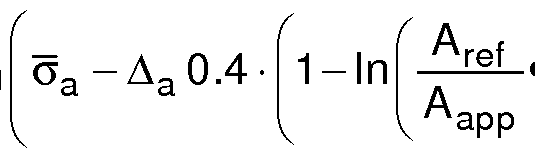
- Thin glass element 100 is provided, which is in development of the invention under tensile stress, in particular due to a bending load, wherein the tensile stress is smaller than the following term:
- ⁇ T a and ⁇ J e are mean values of the tensile stress at breakage of samples of the glass element under bending stress, where Lref is the edge length and A re f is the area of the samples, where G a is the mean value of the tensile stress at
- a apP is the area of the thin glass element and L apP is the added edge length of opposite edges of the glass element and ⁇ is a predetermined maximum break quota within a period of at least six months.
- the predetermined maximum fracture rate ⁇ is preferably 0, 1 or less (ie at most 10%), more preferably less than 0.05, (less than 5%).
- Thin glass member 100 is provided, which is set below a tensile stress G apP , which is smaller than the above-mentioned term (1).
- the tensile stress can be caused by, for example, rolling up or even mounting on a support under forced bending.
- the glass element be placed under a tensile stress ⁇ which is less than
- the minimum bending radius R with the tensile stress G apP has the following relationship:
- E denotes the Young's modulus
- t the thickness of the thin glass
- V the Poisson's number of the glass. Preferred glass thicknesses are at the top of the description
- End faces are, as already described with reference to FIG. 1, have been produced by separating borders 110, 111.
- the method with which the parameters of the above equations are determined is also described in detail in PCT / EP2014 / 070826, the content of which in this respect also fully relates to the subject matter of the present invention
- Breaking tension, or the corresponding bending radii are recorded at break and based on these data statistical parameters determined and based on these parameters, an area for a bending radius
- the invention now provides a thin glass element 100
- edges 101 for example in the form of a thin glass roll with a rolled thin glass 1 in the form of a thin glass ribbon with a length of preferably at least 10 meters, wherein the inner radius of the rolled thin glass or more generally the bending radius of the bent thin glass element in the range of
- Time-delayed fractures are caused in particular by stress corrosion cracking.
- Thin glass element 100 in the form of a roll 3 with a rolled up thin glass 1 with a length of preferably at least 10 meters is therefore based on
- Truss race is made and the thin glass ribbon is wound into a roll, wherein the inner radius of the roll, which is the radius of the innermost layer of the
- Thin glass ribbon is chosen to be in the range of Rmin according to equation (8) to R ma x according to equation (9), where t is a predetermined minimum duration in days which the thin glass roll should survive without breakage.
- t is a predetermined minimum duration in days which the thin glass roll should survive without breakage.
- equations (8) and (9) are adjusted so that the fractional quota within a given minimum duration is generally less than 0, 1, preferably less than 0, 05.
- edges 101 according to the invention and their improved strength influence the parameters s and ⁇ R>.
- the mean value ⁇ R> as compared with samples not in accordance with the invention is also overall
- the variance s may increase or also become smaller than samples produced according to the invention.
Landscapes
- Chemical & Material Sciences (AREA)
- Materials Engineering (AREA)
- Engineering & Computer Science (AREA)
- Organic Chemistry (AREA)
- Chemical Kinetics & Catalysis (AREA)
- Geochemistry & Mineralogy (AREA)
- General Chemical & Material Sciences (AREA)
- Life Sciences & Earth Sciences (AREA)
- Physics & Mathematics (AREA)
- Health & Medical Sciences (AREA)
- Optics & Photonics (AREA)
- Toxicology (AREA)
- Thermal Sciences (AREA)
- Re-Forming, After-Treatment, Cutting And Transporting Of Glass Products (AREA)
- Laser Beam Processing (AREA)
Abstract
Description





Claims



Priority Applications (4)
| Application Number | Priority Date | Filing Date | Title |
|---|---|---|---|
| CN201680019014.5A CN107428588B (zh) | 2015-03-27 | 2016-03-24 | 通过激光切割玻璃的方法以及根据所述方法生产的玻璃 |
| DE112016000195.9T DE112016000195A5 (de) | 2015-03-27 | 2016-03-24 | Verfahren zum Trennen von Glas mittels eines Lasers, sowie verfahrensgemäß hergestelltes Glaserzeugnis |
| JP2017550770A JP6726206B2 (ja) | 2015-03-27 | 2016-03-24 | レーザを用いてガラスを分断するための方法ならびに本発明により製造されたガラス製品 |
| US15/674,124 US10538453B2 (en) | 2015-03-27 | 2017-08-10 | Method for cutting glass using a laser, and glass produced according to the method |
Applications Claiming Priority (2)
| Application Number | Priority Date | Filing Date | Title |
|---|---|---|---|
| DE102015104802.7 | 2015-03-27 | ||
| DE102015104802.7A DE102015104802A1 (de) | 2015-03-27 | 2015-03-27 | Verfahren zum Trennen von Glas mittels eines Lasers, sowie verfahrensgemäß hergestelltes Glaserzeugnis |
Related Child Applications (1)
| Application Number | Title | Priority Date | Filing Date |
|---|---|---|---|
| US15/674,124 Continuation US10538453B2 (en) | 2015-03-27 | 2017-08-10 | Method for cutting glass using a laser, and glass produced according to the method |
Publications (1)
| Publication Number | Publication Date |
|---|---|
| WO2016156235A1 true WO2016156235A1 (de) | 2016-10-06 |
Family
ID=55589897
Family Applications (1)
| Application Number | Title | Priority Date | Filing Date |
|---|---|---|---|
| PCT/EP2016/056613 Ceased WO2016156235A1 (de) | 2015-03-27 | 2016-03-24 | VERFAHREN ZUM TRENNEN VON GLAS MITTELS EINES LASERS, SOWIE VERFAHRENSGEMÄß HERGESTELLTES GLASERZEUGNIS |
Country Status (5)
| Country | Link |
|---|---|
| US (1) | US10538453B2 (de) |
| JP (1) | JP6726206B2 (de) |
| CN (1) | CN107428588B (de) |
| DE (2) | DE102015104802A1 (de) |
| WO (1) | WO2016156235A1 (de) |
Cited By (1)
| Publication number | Priority date | Publication date | Assignee | Title |
|---|---|---|---|---|
| EP3967667A1 (de) | 2020-09-15 | 2022-03-16 | Schott Ag | Verfahren und vorrichtung zum zuschneiden von glasfolien |
Families Citing this family (9)
| Publication number | Priority date | Publication date | Assignee | Title |
|---|---|---|---|---|
| DE102018100443A1 (de) * | 2018-01-10 | 2019-07-11 | Schott Ag | Verfahren und Vorrichtung zur Herstellung von Glasvorprodukten und von Glasprodukten |
| DE102019113635A1 (de) * | 2019-05-22 | 2020-11-26 | Schott Ag | Verfahren und Vorrichtung zur Verarbeitung von Glaselementen |
| DE102019129036A1 (de) * | 2019-10-28 | 2021-04-29 | Schott Ag | Verfahren zur Herstellung von Glasscheiben und verfahrensgemäß hergestellte Glasscheibe sowie deren Verwendung |
| DE102020100051A1 (de) * | 2020-01-03 | 2021-07-08 | Schott Ag | Verfahren zur Bearbeitung sprödharter Materialien |
| CN110963691A (zh) * | 2020-01-17 | 2020-04-07 | 刘洋 | 一种长条形玻璃快速切割生产设备 |
| KR20210110510A (ko) | 2020-02-28 | 2021-09-08 | 쇼오트 아게 | 유리 부재의 분리 방법 및 유리 서브부재 |
| EP3875436B1 (de) * | 2020-03-06 | 2024-01-17 | Schott Ag | Verfahren zum vorbereiten und/oder durchführen des trennens eines substratelements und substratteilelement |
| CN113333966B (zh) * | 2021-05-13 | 2022-12-09 | 西安交通大学 | 一种基于飞秒激光光丝效应的薄石英玻璃切割方法 |
| CN117532279B (zh) * | 2024-01-08 | 2024-03-19 | 山西金鼎泰金属制品股份有限公司 | 一种用于高压管路的连接法兰加工方法 |
Citations (21)
| Publication number | Priority date | Publication date | Assignee | Title |
|---|---|---|---|---|
| DE19715537A1 (de) * | 1997-04-14 | 1997-10-09 | Schott Glaswerke | Verfahren und Vorrichtung zum Durchtrennen von flachen Werkstücken aus sprödem Material, insbesondere aus Glas |
| DE19856347A1 (de) * | 1998-12-07 | 2000-03-09 | Schott Spezialglas Gmbh | Verfahren und Vorrichtung zum Schneiden eines dünnen Werkstücks aus sprödbrüchigem Werkstoff |
| US6327875B1 (en) | 1999-03-09 | 2001-12-11 | Corning Incorporated | Control of median crack depth in laser scoring |
| US20020032117A1 (en) | 2000-01-12 | 2002-03-14 | Ulrich Peuchert | Alkali-free aluminoborosilicate glass, and uses thereof |
| WO2002048059A1 (de) * | 2000-12-15 | 2002-06-20 | Lzh Laserzentrum Hannover E.V. | Verfahren zum durchtrennen von bauteilen aus glas, keramik, glaskeramik oder dergleichen durch erzeugung eines thermischen spannungsrisses an dem bauteil entlang einer trennzone |
| US20030145624A1 (en) * | 2000-06-21 | 2003-08-07 | Thomas Luettgens | Method and device for manufacturing glass panes of any desired contour from sheet glass |
| CN1541155A (zh) * | 2001-08-10 | 2004-10-27 | 三星宝石工业株式会社 | 脆性材料基板的划线方法及划线装置 |
| WO2006002168A1 (en) * | 2004-06-21 | 2006-01-05 | Applied Photonics, Inc. | Device, system and method for cutting, cleaving or separating a substrate material |
| CA2602997A1 (en) * | 2006-09-20 | 2008-03-20 | Institut National D'optique | Laser-based ablation method and optical system |
| WO2011026074A1 (en) | 2009-08-31 | 2011-03-03 | Corning Incorporated | Methods for laser scribing and breaking thin glass |
| US20110084426A1 (en) * | 2009-10-13 | 2011-04-14 | Canon Kabushiki Kaisha | Method of notching brittle material, method of making member having notch, and method of making display device |
| US20120000894A1 (en) * | 2009-03-20 | 2012-01-05 | Carrier Corporation | Precision laser scoring |
| US20120135195A1 (en) * | 2010-11-30 | 2012-05-31 | Gregory Scott Glaesemann | Methods for separating glass articles from strengthened glass substrate sheets |
| US20130126576A1 (en) | 2011-11-18 | 2013-05-23 | Dale Charles Marshall | Apparatus and method characterizing glass sheets |
| US20130207058A1 (en) | 2011-08-12 | 2013-08-15 | Schott Ag | Arsenic and antimony free, titanium oxide containing borosilicate glass and methods for the production thereof |
| US20130224433A1 (en) * | 2012-02-29 | 2013-08-29 | Electro Scientific Industries, Inc. | Method and apparatus for machining strengthened glass and articles produced thereby |
| US20130323469A1 (en) * | 2012-06-05 | 2013-12-05 | Corning Incorporated | Methods of cutting glass using a laser |
| US20140113797A1 (en) * | 2011-06-28 | 2014-04-24 | Ihi Corporation | Device and method for cutting brittle member and cut-out brittle member |
| US20140199519A1 (en) * | 2013-01-15 | 2014-07-17 | Corning Laser Technologies GmbH | Method and device for the laser-based machining of sheet-like substrates |
| US20150059411A1 (en) * | 2013-08-29 | 2015-03-05 | Corning Incorporated | Method of separating a glass sheet from a carrier |
| DE102014113149A1 (de) | 2014-09-12 | 2016-03-17 | Schott Ag | Dünnglas-Rolle und Verfahren zu dessen Herstellung |
Family Cites Families (8)
| Publication number | Priority date | Publication date | Assignee | Title |
|---|---|---|---|---|
| MY120533A (en) * | 1997-04-14 | 2005-11-30 | Schott Ag | Method and apparatus for cutting through a flat workpiece made of brittle material, especially glass. |
| US6252197B1 (en) * | 1998-12-01 | 2001-06-26 | Accudyne Display And Semiconductor Systems, Inc. | Method and apparatus for separating non-metallic substrates utilizing a supplemental mechanical force applicator |
| AU2003220835A1 (en) * | 2002-03-12 | 2003-09-22 | Mitsuboshi Diamond Industrial Co., Ltd. | Method and system for machining fragile material |
| TWI577653B (zh) * | 2007-03-02 | 2017-04-11 | 日本電氣硝子股份有限公司 | 強化板玻璃及其製造方法 |
| JP5060880B2 (ja) * | 2007-09-11 | 2012-10-31 | 三星ダイヤモンド工業株式会社 | 脆性材料基板の分断装置および分断方法 |
| JP5345334B2 (ja) * | 2008-04-08 | 2013-11-20 | 株式会社レミ | 脆性材料の熱応力割断方法 |
| KR101041137B1 (ko) * | 2009-03-25 | 2011-06-13 | 삼성모바일디스플레이주식회사 | 기판 절단 장치 및 이를 이용한 기판 절단 방법 |
| DE102013110803A1 (de) | 2013-09-30 | 2015-04-02 | Schott Ag | Verfahren zur Weiterverarbeitung von Dünnglas und verfahrensgemäß hergestelltes Dünnglas |
-
2015
- 2015-03-27 DE DE102015104802.7A patent/DE102015104802A1/de not_active Withdrawn
-
2016
- 2016-03-24 DE DE112016000195.9T patent/DE112016000195A5/de not_active Withdrawn
- 2016-03-24 CN CN201680019014.5A patent/CN107428588B/zh active Active
- 2016-03-24 JP JP2017550770A patent/JP6726206B2/ja not_active Expired - Fee Related
- 2016-03-24 WO PCT/EP2016/056613 patent/WO2016156235A1/de not_active Ceased
-
2017
- 2017-08-10 US US15/674,124 patent/US10538453B2/en active Active
Patent Citations (21)
| Publication number | Priority date | Publication date | Assignee | Title |
|---|---|---|---|---|
| DE19715537A1 (de) * | 1997-04-14 | 1997-10-09 | Schott Glaswerke | Verfahren und Vorrichtung zum Durchtrennen von flachen Werkstücken aus sprödem Material, insbesondere aus Glas |
| DE19856347A1 (de) * | 1998-12-07 | 2000-03-09 | Schott Spezialglas Gmbh | Verfahren und Vorrichtung zum Schneiden eines dünnen Werkstücks aus sprödbrüchigem Werkstoff |
| US6327875B1 (en) | 1999-03-09 | 2001-12-11 | Corning Incorporated | Control of median crack depth in laser scoring |
| US20020032117A1 (en) | 2000-01-12 | 2002-03-14 | Ulrich Peuchert | Alkali-free aluminoborosilicate glass, and uses thereof |
| US20030145624A1 (en) * | 2000-06-21 | 2003-08-07 | Thomas Luettgens | Method and device for manufacturing glass panes of any desired contour from sheet glass |
| WO2002048059A1 (de) * | 2000-12-15 | 2002-06-20 | Lzh Laserzentrum Hannover E.V. | Verfahren zum durchtrennen von bauteilen aus glas, keramik, glaskeramik oder dergleichen durch erzeugung eines thermischen spannungsrisses an dem bauteil entlang einer trennzone |
| CN1541155A (zh) * | 2001-08-10 | 2004-10-27 | 三星宝石工业株式会社 | 脆性材料基板的划线方法及划线装置 |
| WO2006002168A1 (en) * | 2004-06-21 | 2006-01-05 | Applied Photonics, Inc. | Device, system and method for cutting, cleaving or separating a substrate material |
| CA2602997A1 (en) * | 2006-09-20 | 2008-03-20 | Institut National D'optique | Laser-based ablation method and optical system |
| US20120000894A1 (en) * | 2009-03-20 | 2012-01-05 | Carrier Corporation | Precision laser scoring |
| WO2011026074A1 (en) | 2009-08-31 | 2011-03-03 | Corning Incorporated | Methods for laser scribing and breaking thin glass |
| US20110084426A1 (en) * | 2009-10-13 | 2011-04-14 | Canon Kabushiki Kaisha | Method of notching brittle material, method of making member having notch, and method of making display device |
| US20120135195A1 (en) * | 2010-11-30 | 2012-05-31 | Gregory Scott Glaesemann | Methods for separating glass articles from strengthened glass substrate sheets |
| US20140113797A1 (en) * | 2011-06-28 | 2014-04-24 | Ihi Corporation | Device and method for cutting brittle member and cut-out brittle member |
| US20130207058A1 (en) | 2011-08-12 | 2013-08-15 | Schott Ag | Arsenic and antimony free, titanium oxide containing borosilicate glass and methods for the production thereof |
| US20130126576A1 (en) | 2011-11-18 | 2013-05-23 | Dale Charles Marshall | Apparatus and method characterizing glass sheets |
| US20130224433A1 (en) * | 2012-02-29 | 2013-08-29 | Electro Scientific Industries, Inc. | Method and apparatus for machining strengthened glass and articles produced thereby |
| US20130323469A1 (en) * | 2012-06-05 | 2013-12-05 | Corning Incorporated | Methods of cutting glass using a laser |
| US20140199519A1 (en) * | 2013-01-15 | 2014-07-17 | Corning Laser Technologies GmbH | Method and device for the laser-based machining of sheet-like substrates |
| US20150059411A1 (en) * | 2013-08-29 | 2015-03-05 | Corning Incorporated | Method of separating a glass sheet from a carrier |
| DE102014113149A1 (de) | 2014-09-12 | 2016-03-17 | Schott Ag | Dünnglas-Rolle und Verfahren zu dessen Herstellung |
Cited By (2)
| Publication number | Priority date | Publication date | Assignee | Title |
|---|---|---|---|---|
| EP3967667A1 (de) | 2020-09-15 | 2022-03-16 | Schott Ag | Verfahren und vorrichtung zum zuschneiden von glasfolien |
| DE102020123928A1 (de) | 2020-09-15 | 2022-03-17 | Schott Ag | Verfahren und Vorrichtung zum Zuschneiden von Glasfolien |
Also Published As
| Publication number | Publication date |
|---|---|
| JP2018512367A (ja) | 2018-05-17 |
| DE102015104802A1 (de) | 2016-09-29 |
| US20180022631A1 (en) | 2018-01-25 |
| JP6726206B2 (ja) | 2020-07-22 |
| CN107428588B (zh) | 2022-02-25 |
| US10538453B2 (en) | 2020-01-21 |
| CN107428588A (zh) | 2017-12-01 |
| DE112016000195A5 (de) | 2017-08-31 |
Similar Documents
| Publication | Publication Date | Title |
|---|---|---|
| DE102015104802A1 (de) | Verfahren zum Trennen von Glas mittels eines Lasers, sowie verfahrensgemäß hergestelltes Glaserzeugnis | |
| WO2016156234A1 (de) | Verfahren und vorrichtung zum kontinuierlichen trennen von glas | |
| WO2013050166A1 (de) | Verfahren zum schneiden eines dünnglases mit spezieller ausbildung der kante | |
| DE102016116258B4 (de) | Vorrichtung und Verfahren zur Belastungsprüfung von Scheiben eines sprödharten Materials | |
| WO2016156233A1 (de) | Verfahren und vorrichtung zum kontinuierlichen trennen von glas | |
| EP3334697A1 (de) | Verfahren zum schneiden einer dünnen glassschicht | |
| DE1916075A1 (de) | Verfahren und Vorrichtung zum Schneiden von Glas | |
| EP2945769B1 (de) | Verfahren und vorrichtung zum laserbasierten bearbeiten von flächigen substraten unter verwendung einer laserstrahlbrennlinie ; entsprechende glasgegenstände | |
| EP1860075A1 (de) | Verfahren und Vorrichtung zum Randbeschneiden eines Floatglasbandes | |
| DE2346991C2 (de) | Verfahren zum Abschneiden eines Randstreifens von Flachglas | |
| DE102019129036A1 (de) | Verfahren zur Herstellung von Glasscheiben und verfahrensgemäß hergestellte Glasscheibe sowie deren Verwendung | |
| DE2451004A1 (de) | Verfahren zum schneiden eines feuerbestaendigen materials | |
| DE102017101808A1 (de) | Verfahren zur Dickenkontrolle eines Substrates | |
| WO2005107998A1 (de) | Vorrichtung zum durchtrennenden bearbeiten von bauteilen aus sprödbrüchigem material mit spannungsfreier bauteillagerung | |
| DE102011084129A1 (de) | Glasfolie mit speziell ausgebildeter Kante | |
| DE102019113635A1 (de) | Verfahren und Vorrichtung zur Verarbeitung von Glaselementen | |
| DE4411037C2 (de) | Verfahren zum Schneiden von Hohlglas | |
| DE102019116560A1 (de) | Vorrichtung und Verfahren zum Trennen einer Verbundsicherheitsglastafel | |
| DE102014109792A1 (de) | Verfahren zum Erzeugen eines langzeitstabilen Anrisses auf der Oberfläche eines Elements aus sprödhartem Material | |
| DE102011006738B4 (de) | Verfahren zum vollständigen Vereinzeln von Hohlglas und Herstellungsverfahren für einen Glashohlkörper oder Behälterglas | |
| DE2813302C2 (de) | Verfahren und Vorrichtung zum geradlinigen Schneiden von Flachglas mit Hilfe von thermisch induzierten Spannungen | |
| EP3967667A1 (de) | Verfahren und vorrichtung zum zuschneiden von glasfolien | |
| DE102011084131A1 (de) | Glasfolie mit speziell ausgebildeter Kante | |
| DE112021000639T5 (de) | Verfahren zur herstellung eines glasfilms | |
| WO2026008462A1 (de) | Verfahren zur herstellung von ultradünnen elementen aus glasbasiertem material, ultradünnes element aus glasbasiertem material sowie dessen verwendung |
Legal Events
| Date | Code | Title | Description |
|---|---|---|---|
| 121 | Ep: the epo has been informed by wipo that ep was designated in this application |
Ref document number: 16711669 Country of ref document: EP Kind code of ref document: A1 |
|
| WWE | Wipo information: entry into national phase |
Ref document number: 112016000195 Country of ref document: DE |
|
| REG | Reference to national code |
Ref country code: DE Ref legal event code: R225 Ref document number: 112016000195 Country of ref document: DE |
|
| ENP | Entry into the national phase |
Ref document number: 2017550770 Country of ref document: JP Kind code of ref document: A |
|
| 122 | Ep: pct application non-entry in european phase |
Ref document number: 16711669 Country of ref document: EP Kind code of ref document: A1 |