WO2016152970A1 - バルブ制御装置及びバルブシステム - Google Patents
バルブ制御装置及びバルブシステム Download PDFInfo
- Publication number
- WO2016152970A1 WO2016152970A1 PCT/JP2016/059368 JP2016059368W WO2016152970A1 WO 2016152970 A1 WO2016152970 A1 WO 2016152970A1 JP 2016059368 W JP2016059368 W JP 2016059368W WO 2016152970 A1 WO2016152970 A1 WO 2016152970A1
- Authority
- WO
- WIPO (PCT)
- Prior art keywords
- valve
- signal
- lift amount
- drive signal
- drive
- Prior art date
- Legal status (The legal status is an assumption and is not a legal conclusion. Google has not performed a legal analysis and makes no representation as to the accuracy of the status listed.)
- Ceased
Links
Images


Classifications
-
- F—MECHANICAL ENGINEERING; LIGHTING; HEATING; WEAPONS; BLASTING
- F02—COMBUSTION ENGINES; HOT-GAS OR COMBUSTION-PRODUCT ENGINE PLANTS
- F02B—INTERNAL-COMBUSTION PISTON ENGINES; COMBUSTION ENGINES IN GENERAL
- F02B37/00—Engines characterised by provision of pumps driven at least for part of the time by exhaust
- F02B37/12—Control of the pumps
- F02B37/18—Control of the pumps by bypassing exhaust from the inlet to the outlet of turbine or to the atmosphere
- F02B37/183—Arrangements of bypass valves or actuators therefor
- F02B37/186—Arrangements of actuators or linkage for bypass valves
-
- F—MECHANICAL ENGINEERING; LIGHTING; HEATING; WEAPONS; BLASTING
- F02—COMBUSTION ENGINES; HOT-GAS OR COMBUSTION-PRODUCT ENGINE PLANTS
- F02B—INTERNAL-COMBUSTION PISTON ENGINES; COMBUSTION ENGINES IN GENERAL
- F02B39/00—Component parts, details, or accessories relating to, driven charging or scavenging pumps, not provided for in groups F02B33/00 - F02B37/00
- F02B39/16—Other safety measures for, or other control of, pumps
-
- F—MECHANICAL ENGINEERING; LIGHTING; HEATING; WEAPONS; BLASTING
- F02—COMBUSTION ENGINES; HOT-GAS OR COMBUSTION-PRODUCT ENGINE PLANTS
- F02D—CONTROLLING COMBUSTION ENGINES
- F02D41/00—Electrical control of supply of combustible mixture or its constituents
- F02D41/02—Circuit arrangements for generating control signals
- F02D41/04—Introducing corrections for particular operating conditions
- F02D41/06—Introducing corrections for particular operating conditions for engine starting or warming up
- F02D41/062—Introducing corrections for particular operating conditions for engine starting or warming up for starting
-
- F—MECHANICAL ENGINEERING; LIGHTING; HEATING; WEAPONS; BLASTING
- F02—COMBUSTION ENGINES; HOT-GAS OR COMBUSTION-PRODUCT ENGINE PLANTS
- F02D—CONTROLLING COMBUSTION ENGINES
- F02D41/00—Electrical control of supply of combustible mixture or its constituents
- F02D41/22—Safety or indicating devices for abnormal conditions
- F02D41/221—Safety or indicating devices for abnormal conditions relating to the failure of actuators or electrically driven elements
-
- F—MECHANICAL ENGINEERING; LIGHTING; HEATING; WEAPONS; BLASTING
- F02—COMBUSTION ENGINES; HOT-GAS OR COMBUSTION-PRODUCT ENGINE PLANTS
- F02D—CONTROLLING COMBUSTION ENGINES
- F02D41/00—Electrical control of supply of combustible mixture or its constituents
- F02D41/22—Safety or indicating devices for abnormal conditions
- F02D41/222—Safety or indicating devices for abnormal conditions relating to the failure of sensors or parameter detection devices
-
- F—MECHANICAL ENGINEERING; LIGHTING; HEATING; WEAPONS; BLASTING
- F02—COMBUSTION ENGINES; HOT-GAS OR COMBUSTION-PRODUCT ENGINE PLANTS
- F02D—CONTROLLING COMBUSTION ENGINES
- F02D2200/00—Input parameters for engine control
- F02D2200/02—Input parameters for engine control the parameters being related to the engine
- F02D2200/021—Engine temperature
-
- Y—GENERAL TAGGING OF NEW TECHNOLOGICAL DEVELOPMENTS; GENERAL TAGGING OF CROSS-SECTIONAL TECHNOLOGIES SPANNING OVER SEVERAL SECTIONS OF THE IPC; TECHNICAL SUBJECTS COVERED BY FORMER USPC CROSS-REFERENCE ART COLLECTIONS [XRACs] AND DIGESTS
- Y02—TECHNOLOGIES OR APPLICATIONS FOR MITIGATION OR ADAPTATION AGAINST CLIMATE CHANGE
- Y02T—CLIMATE CHANGE MITIGATION TECHNOLOGIES RELATED TO TRANSPORTATION
- Y02T10/00—Road transport of goods or passengers
- Y02T10/10—Internal combustion engine [ICE] based vehicles
- Y02T10/12—Improving ICE efficiencies
-
- Y—GENERAL TAGGING OF NEW TECHNOLOGICAL DEVELOPMENTS; GENERAL TAGGING OF CROSS-SECTIONAL TECHNOLOGIES SPANNING OVER SEVERAL SECTIONS OF THE IPC; TECHNICAL SUBJECTS COVERED BY FORMER USPC CROSS-REFERENCE ART COLLECTIONS [XRACs] AND DIGESTS
- Y02—TECHNOLOGIES OR APPLICATIONS FOR MITIGATION OR ADAPTATION AGAINST CLIMATE CHANGE
- Y02T—CLIMATE CHANGE MITIGATION TECHNOLOGIES RELATED TO TRANSPORTATION
- Y02T10/00—Road transport of goods or passengers
- Y02T10/10—Internal combustion engine [ICE] based vehicles
- Y02T10/40—Engine management systems
Definitions
- the present invention relates to a valve control device and a valve system.
- the wastegate valve is a type of control valve provided in the bypass path of the engine exhaust gas in the supercharger, and appropriately controls the supercharging pressure of the combustion air supplied to the engine.
- Patent Document 1 listed below discloses a wastegate valve control device for an internal combustion engine with a supercharger that copes with the abnormality by controlling an air bypass valve when an abnormality occurs in the drive mechanism of the wastegate valve. ing.
- Patent Document 1 can be applied to an engine in which an air bypass valve is provided in the exhaust system, and therefore cannot be applied to an engine that does not include an air bypass valve. Therefore, development of a technology capable of coping with an abnormality in the drive mechanism of the wastegate valve regardless of the presence or absence of the air bypass valve is eagerly desired.
- An aspect according to the present invention has been made in view of the above-described circumstances, and provides a valve control device and a valve system that can cope with an abnormality in a drive mechanism of a target valve without using another valve such as an air bypass valve.
- the purpose is to provide.
- a valve control device is a valve control device that controls a valve drive mechanism based on a valve opening signal and an engine start signal, and that starts the engine based on the start signal.
- the drive signal generation unit Prior to the generation of the normal drive signal related to the normal drive of the valve, the drive signal generation unit for generating the test drive signal for performing the test drive of the valve, and the abnormality of the drive mechanism based on the opening signal at the time of the test drive.
- the drive signal generation unit stops generating the test drive signal and the normal drive signal when the abnormality determination unit determines that the drive mechanism is abnormal.
- the abnormality determination unit determines whether the cooling water temperature is equal to or lower than the freezing temperature based on a temperature signal indicating the cooling water temperature of the engine, and the cooling water temperature is the freezing temperature. If the valve opening degree does not follow the control target value at the time of test drive for a predetermined period of time, the icing abnormality of the drive mechanism may be determined.
- the abnormality determination unit determines whether or not the temperature sensor is abnormal based on a sensor failure signal indicating an abnormality of the temperature sensor that detects the coolant temperature of the engine. If it is determined that the temperature sensor is abnormal, the drive signal generation unit may generate a drive signal at a level that can be continuously supplied to the drive mechanism.
- the drive signal generation unit determines stop of the engine based on the start signal, the drive signal generation unit generates a drive signal for fully closing the valve. May be.
- the drive signal generation unit stops generating the test drive signal and the normal drive signal, Thereafter, when it is determined that the cooling water temperature has become higher than the freezing temperature based on the temperature signal, the generation of the normal drive signal may be resumed.
- the valve may be a wastegate valve provided in an engine supercharger.
- a valve system includes the valve, the drive mechanism, and the valve control device according to any one of (1) to (6).
- the test drive signal for test driving the valve is generated, and the drive mechanism is based on the opening signal during the test drive using the test drive signal.
- the drive mechanism is abnormal, the generation of the test drive signal and the normal drive signal is stopped. Therefore, it is possible to provide a valve control device and a valve system that can cope with an abnormality in a drive mechanism of a target valve without using another valve such as an air bypass valve.
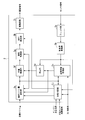
- the valve system and the valve control device include an EWG valve 1, an EWG motor 2, and an EWG control unit 3.
- EWG is an abbreviation for “Electric Waste Gate”.
- the EWG valve 1 is a wastegate valve provided in a bypass path of engine exhaust gas in the supercharger, and adjusts the supercharging pressure of the combustion air supplied to the engine. That is, when the opening degree of the EWG valve 1 is increased, the supercharging pressure is decreased. On the other hand, when the opening degree of the EWG valve 1 is decreased, the supercharging pressure is increased.
- Such an EWG valve 1 is mechanically connected to the EWG motor 2 via a predetermined coupling mechanism, and the opening degree is adjusted (operated) by the driving force of the EWG motor 2.
- the opening degree of the EWG valve 1 is a physical quantity defined by the position (lift amount) of the valve body with respect to the valve seat in the EWG valve 1. That is, when the lift amount increases, that is, when the distance of the valve body to the valve seat increases, the opening degree of the EWG valve 1 increases. On the other hand, when the lift amount decreases, that is, when the distance of the valve body to the valve seat decreases. The opening degree of the EWG valve 1 is lowered.
- the EWG motor 2 is an actuator that drives the EWG valve 1 and is, for example, a DC motor.
- the EWG motor 2 includes a lift sensor 2a that outputs a voltage indicating the lift amount of the EWG valve 1 as a sensor signal (voltage signal).
- Such an EWG motor 2 operates based on a drive signal input from the EWG control unit 3 to operate the opening degree of the EWG valve 1.
- the EWG motor 2 constitutes the drive mechanism in the present embodiment together with the above-described coupling mechanism.
- the sensor signal is an opening signal indicating the opening of the EWG valve 1 (waist gate valve).
- the EWG control unit 3 is a valve control device in the present embodiment, and controls the EWG motor 2 to operate the opening degree of the EWG valve 1.
- the EWG control unit 3 is one control function element in the engine ECU.
- the engine ECU 3 acquires various information (engine ECU information) from the upper control function elements constituting the upper control system in the engine ECU, and the sensor from the lift sensor 2a.
- the EWG motor 2 is controlled by acquiring a signal and generating a drive signal based on the engine ECU information and the sensor signal.
- the engine ECU information is an instruction signal of an engine ECU provided outside the EWG control unit 3 or a signal indicating an operating state of the engine, such as a target lift amount, an IG ON signal, an engine water temperature signal, a water temperature sensor failure signal, etc. It is.
- Such an EWG control unit 3 feedback-controls the EWG motor 2 based on the engine ECU information and the actual lift amount (actual lift amount) in the EWG valve 1.
- the target lift amount is a control target value indicating the opening degree target of the EWG valve 1.
- the IGON signal is a signal indicating the ON / OFF state of the ignition switch, that is, a start signal indicating the start state of the engine.
- the engine water temperature signal is a signal indicating the engine coolant temperature detected by a water temperature sensor (temperature sensor) provided in the engine. Further, the water temperature sensor failure is a signal indicating that the water temperature sensor has failed.
- the EWG control unit 3 includes a filter unit 3a, a control amount conversion unit 3b, a fully closed learning processing unit 3c, a correction unit 3d, a final lift amount setting unit 3e, and a position control unit.
- 3f, a speed control unit 3g, a DUTY setting unit 3h, a drive circuit 3i, and an icing determination unit 3j are provided as functional components.
- the filter unit 3a excluding the icing determination unit 3j, the control amount conversion unit 3b, the fully closed learning processing unit 3c, the correction unit 3d, the final lift amount setting unit 3e, the position control unit 3f, and the speed control unit 3g
- start signal the start signal
- DUTY setting unit 3h and the drive circuit 3i prior to generating a normal drive signal related to normal drive of the EWG valve 1 wipe gate valve
- a drive signal generation unit that generates a test drive signal for performing test drive of the EWG valve 1 is configured.
- the icing determination unit 3j corresponds to an abnormality determination unit that determines abnormality of the drive mechanism based on a sensor signal (opening signal) at the time of test driving of the EWG valve 1.
- the “DUTY” is a term indicating a duty ratio.
- the filter unit 3a converts a sensor signal input from the lift sensor 2a, that is, an analog voltage signal into a digital signal (detected voltage data), and performs median filter processing (digital signal processing) on the digital signal to control amount conversion unit Output to 3b.
- the median filter process is a filter process that removes noise by extracting a median value for each predetermined number of data from detection voltage data that is time-series data.
- the lift sensor 2a that outputs the sensor signal is likely to superimpose various noises because of the relationship provided in the EWG motor 2 attached to the engine. However, the filter unit 3a removes such noise and increases the lift amount (opening degree).
- the detection voltage data shown more accurately is output to the control amount converter 3b.
- moving average processing is generally used for digital signal processing for removing noise.
- the filter unit 3a employs median filter processing.
- a speed control unit 3g is provided in addition to the position control unit 3f, but the speed control unit 3g is superimposed on the actual lift amount in order to calculate the speed control amount using a differential value of the actual lift amount. Susceptible to noise.
- median filter processing is employed instead of moving average processing because of such a speed control unit 3g.
- the control amount conversion unit 3b converts the detected voltage data (voltage amount) into a lift amount (position).
- the control amount conversion unit 3b includes, for example, a conversion table that shows the relationship between the detected voltage data and the lift amount, extracts a lift amount corresponding to the detected voltage data based on the conversion table, and sends it to the fully closed learning processing unit 3c. Output.
- a conversion equation indicating the relationship between the detected voltage data and the lift amount may be stored in advance, and the lift amount corresponding to the detected voltage data may be extracted based on the conversion equation.
- the fully closed learning processing unit 3c is a functional component that learns the lift amount (seat position) when the valve body of the EWG valve 1 is seated on the valve seat as the fully closed lift amount.
- the fully closed lift amount varies according to the temperature of the EWG valve 1 and cannot be treated as a fixed value. Due to such circumstances, the fully-closed learning processing unit 3c is configured so that the valve body of the EWG valve 1 is controlled based on the IG ON signal and the actual lift amount (actual lift amount) input from the control amount conversion unit 3b.
- the lift amount (sitting position) when seated on the seat is learned as the fully closed lift amount.
- the fully closed lift amount has a long-term learning value and a short-term learning value.
- the long-term learning value is a learning value acquired every time the engine is started, while the short-term learning value is a learning value acquired every time the valve body is seated. That is, when the fully closed learning processing unit 3c determines that the engine is started based on the IG ON signal, the fully closed lift amount when the valve body of the EWG valve 1 is first seated after starting the engine is determined as a long-term learning value.
- the fully-closed learning processing unit 3c stores the fully-closed lift amount at that time as a short-term learned value every time the valve body of the EWG valve 1 is seated on the valve seat, regardless of the start of the engine.
- the fully closed learning processing unit 3c acquires a long-term learning value by using an IG ON signal indicating engine start-up in addition to the actual lift amount (actual lift amount) input from the control amount conversion unit 3b.
- the short-term learning value is acquired based only on the actual lift amount input from the control amount conversion unit 3b.
- the fully closed learning processing unit 3c outputs the long-term learning value and the short-term learning value to the final lift amount setting unit 3e, and outputs only the short-term learning value to the correction unit 3d.
- the correction unit 3d is a functional component that corrects the actual lift amount input from the control amount conversion unit 3b based on the short-term learning value input from the fully closed learning processing unit 3c. That is, the correction unit 3d calculates a lift amount (corrected lift amount) based on the short-term learned value by taking a difference between the actual lift amount and the short-term learned value, and uses the corrected lift amount as the position control unit 3f and Output to the speed controller 3g.
- the final lift amount setting unit 3e is a target lift amount input from the engine ECU as one of the engine ECU information, a long-term learning value and a short-term learning value input from the fully closed learning processing unit 3c, and a correction unit 3d.
- the final target lift amount (control target value) is set based on the corrected lift amount.
- the target lift amount is a signal that designates the lift amount (opening degree) of the EWG valve 1 as a square-wave voltage value.
- the final lift amount setting unit 3e applies a specific process to the target lift amount when the valve body of the EWG valve 1 is seated on the valve seat with respect to such a target lift amount. A final target lift amount that can be soft-landed is generated.
- the final lift amount setting unit 3e divides the period from the start of movement (lowering with respect to the valve seat) until the valve body is seated until the seat is seated into two periods, the previous period and the subsequent period.
- the final target lift amount (control target value) for soft landing on the valve seat is generated by moving the valve body relatively slowly in the subsequent period while lowering at the maximum speed in the previous period.
- the final lift amount setting unit 3e sets a switching point (soft landing start lift amount) between the previous period and the subsequent period and a final stop target lift amount of the valve body based on the long-term learning value and the short-term learning value. .
- the final target lift amount is a control target value (normal final target lift amount) for normally driving the EWG valve 1.
- the final lift amount setting unit 3e generates a final target lift amount (test final target lift amount) for performing the test drive of the EWG valve 1 separately from the normal drive of the EWG valve 1. That is, the final lift amount setting unit 3e generates a test final target lift amount when a test signal generation instruction is input from the icing determination unit 3j.
- the final target lift amount for the test is the one that maintains the test lift amount for a certain period of time after raising the lift amount to a predetermined test lift amount and then starts the soft landing. It is.
- the position control unit 3f generates a position operation amount and outputs it to the speed control unit 3g. That is, the position control unit 3f performs a known PID process on the difference between the final target lift amount (control target value) input from the final lift amount setting unit 3e and the corrected lift amount input from the correction unit 3d.
- the position operation amount is generated by The details of the PID processing, that is, the processing content, gain, and the like are appropriately set according to the performance (control performance) required in the control of the EWG valve 1.
- the speed control unit 3g generates a speed operation amount based on the position operation amount input from the position control unit 3f and the correction lift amount input from the correction unit 3d, and outputs the speed operation amount to the DUTY setting unit 3h. That is, the speed control unit 3g performs a limiter process on the position operation amount input from the position control unit 3f, and performs a differentiation process on the correction lift amount input from the correction unit 3d.
- the speed control unit 3g generates a speed operation amount by performing a known PID process on the difference between the position operation amount after the limiter process and the lift speed obtained by the differentiation process.
- the processing content, gain, and the like are appropriately set according to the performance (control performance) required in the control of the EWG valve 1.
- the drive circuit 3i is a pulse drive type motor drive circuit. That is, the drive circuit 3i converts DC power into PWM power based on a PWM (Pulse Width Modulation) signal input as a control signal from the DUTY setting unit 3h, and outputs the PWM power to the EWG motor 2 as a drive signal. To do.
- the drive signal generated by the drive circuit 3i based on the normal final target lift amount described above is a normal drive signal
- the drive signal generated by the drive circuit 3i based on the final test target lift amount is a test drive. Signal.
- the DUTY setting unit 3h is a PWM signal generator that generates the PWM signal based on the speed operation amount input from the speed control unit 3g. Further, the DUTY setting unit 3h has a function (DUTY limiter) for performing a limiter process on the speed operation amount. That is, the DUTY setting unit 3h generates a PWM signal that restricts the upper limit of the duty ratio of the PWM signal, that is, the maximum rotation speed of the EWG motor 2, by performing a limiter process on the speed operation amount. Further, when a DUTY restriction instruction is input from the icing determination unit 3j, the DUTY setting unit 3h limits the DUTY of the PWM signal to a predetermined value regardless of the speed operation amount input from the speed control unit 3g.
- DUTY limiter for performing a limiter process on the speed operation amount. That is, the DUTY setting unit 3h generates a PWM signal that restricts the upper limit of the duty ratio of the PWM signal, that is, the maximum rotation speed of
- the icing determination unit 3j includes an IG ON signal, an engine water temperature signal (temperature signal) and a water temperature sensor failure signal input from the engine ECU, an actual lift amount input from the control amount conversion unit, and a final lift amount setting unit 3e.
- the test signal generation instruction and the DUTY restriction instruction described above are generated based on the final target lift amount input from the above.
- the icing determination unit 3j is an abnormality determination unit in the present embodiment.
- the icing determination unit 3j determines that the engine is started based on the IG ON signal, the test signal generation that instructs to generate the test target lift amount prior to the final target lift amount related to the normal drive of the EWG valve 1 is generated.
- the instruction is output to the final lift amount setting unit 3e.
- the icing determination unit 3j determines whether or not the icing abnormality of the drive mechanism of the EWG valve 1 has occurred based on the actual lift amount at the time of the test driving of the EWG valve 1 based on the target lift amount for testing. When this occurs, a DUTY restriction instruction is output to the DUTY setting unit 3h.
- the above is the configuration of the valve system and the valve control device according to the present embodiment.
- the valve control device in the present embodiment is a control device that uses an EWG valve 1 (waist gate valve) provided as an accessory to the supercharger as a control target valve.
- EWG valve 1 wipe gate valve
- the basic operation (normal operation) of the EWG control unit 3 (valve control device) in the present embodiment is to generate a drive signal based on the target lift amount and the sensor signal based on the feedback control method. Then, by operating the EWG motor 2 based on this drive signal, the opening degree of the EWG valve 1 is adjusted along the target lift amount.
- the EWG control unit 3 performs a test operation prior to such a basic operation (normal operation) when the engine is started.
- a test operation it is determined whether or not icing abnormality has occurred in the drive mechanism of the EWG valve 1, that is, the EWG motor 2 and the coupling mechanism, and the operation of the EWG motor 2 is controlled based on the determination result.
- the basic operation normal operation
- the test operation will be described first, and then the test operation will be described.
- the final lift amount setting unit 3e has a target lift amount input from the engine ECU (upper control system), a long-term learning value and a short-term learning value input from the fully-closed learning processing unit 3c, and correction in normal driving of the EWG valve 1.
- a final target lift amount (control target value) for normal driving is set based on the corrected lift amount input from the unit 3d. That is, the final lift amount setting unit 3e uses the long-term learning value and the short-term learning value for the target lift amount, which is a square-wave voltage signal, so that the falling portion and the fully closed time when the EWG valve 1 is fully closed are used.
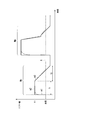
- the normal final target lift amount Ma as shown in FIG. 3 is generated by correcting the low level part that specifies the lift amount.
- a waveform A indicated by a one-dot chain line indicates a change in the actual lift amount with respect to the normal final target lift amount Ma.
- the final lift amount setting unit 3e sets the start lift amount (soft landing start lift amount Lk) and the target stop lift amount Lt when the valve body of the EWG valve 1 is soft landing with respect to the valve seat for a long period of time. Based on the learning value, the short-term learning value, and the specified value (constant), settings are made as follows.
- the final lift amount setting unit 3e monitors the correction lift amount sequentially input from the correction unit 3d, and When the corrected lift amount coincides with the soft landing start lift amount Lk, a control target value that reaches the stop target lift amount Lt with a constant inclination (speed) is output.
- the soft landing start lift amount Lk and the stop target lift amount Lt are defined by the long-term learning value, the short-term learning value, and the specified value (constant), but the corrected lift amount is the actual lift amount and the short-term learning as described above.
- the soft landing start lift amount Lk and the stop target lift amount Lt are substantially defined by only the long-term learning value and the specified value (constant).
- the filter unit 3a sequentially samples the sensor signal (analog signal) input from the lift sensor 2a and converts it into detection voltage data (digital signal), and performs median filtering on the detection voltage data. Since the noise component derived from the sensor signal superimposed on the detection voltage data is removed by the median filter processing, the detection voltage data becomes a signal indicating the lift amount more accurately.
- the detected voltage data (voltage amount) from which noise has been removed by the median filter processing is converted into a lift amount by the control amount conversion unit 3b and output to the fully closed learning processing unit 3c, the correction unit 3d, and the icing determination unit 3j. Is done.
- the fully closed learning processing unit 3c uses the IG ON signal input from the engine ECU as a trigger signal, and among the actual lift amounts sequentially input from the control amount conversion unit 3b every time the engine is started, the EWG valve 1
- the lift amount when the valve body is seated on the valve seat is learned as a long-term learning value. That is, the fully-closed learning processing unit 3c determines that the engine is started based on the IG ON signal, and the fully-closed learning processing unit 3c determines whether or not the valve body of the EWG valve 1 is seated on the valve seat.
- the amount of fully closed lift is acquired and updated as a short-term learning value.
- the fully closed learning processing unit 3c stores the long-term learning value in the nonvolatile memory when the engine is stopped, and outputs the stored long-term learning value as the initial value of the short-term learning value when the engine is next started. To do.
- the long-term learning value and the short-term learning value acquired by such learning processing are provided to the final lift amount setting unit 3e and used to generate the above-described final target lift amount, while the short-term learning value is supplied to the correction unit 3d. Supplied. Then, in the correction unit 3d, the corrected lift amount is generated by subtracting the short-term learning value from the actual lift amount.
- the position control unit 3f generates a position operation amount based on the difference between the final target lift amount and the corrected lift amount, and outputs the position operation amount to the speed control unit 3g.
- the speed control unit 3g corrects the position operation amount and the correction.
- a speed manipulated variable is generated based on the difference from the differential value of the lift amount.
- the DUTY setting unit 3h generates a PWM signal whose duty ratio is set according to the speed operation amount and outputs the PWM signal to the drive circuit 3i.
- the drive circuit 3i has a peak value drive signal according to the PWM signal.
- the EWG motor 2 is driven. Since a speed limiter is set in the speed control unit 3g and a DUTY limiter is set in the DUTY setting unit 3h, the maximum rotation speed of the EWG motor 2 is reliably limited within an allowable range.
- the test operation for the basic operation is as follows. That is, when the test signal generation instruction is input from the icing determination unit 3j, the final lift amount setting unit 3e generates a test target lift amount Mb as shown in FIG.
- the icing determination unit 3j determines that the engine is started based on the IG ON signal, it outputs a test signal generation instruction to the final lift amount setting unit 3e. Therefore, the target lift amount for testing Mb is a normal one as shown in FIG. It is generated prior to the final target lift amount Ma.
- Such a test target lift amount Mb is obtained by raising the EWG valve 1 from the lift amount at the time of starting the engine to a predetermined test lift amount L1, and then setting the test lift amount L1 for a predetermined period (determination period T1). It is made to be in a fully closed state after a soft landing period T2 that is maintained over a period of time and then descends at a constant speed. That is, the test target lift amount Mb is a rising portion m1 that rapidly increases from the initial startup value to the test lift amount L1, a flat portion m2 that maintains the test lift amount L1 over a certain period T1, and a soft landing. It consists of a soft landing part m3 that descends at a constant speed over a period T2.
- the icing determination unit 3j generates an EWG by generating a final target lift amount (stop target lift amount) similar to the test target lift amount Mb when the engine start / stop is determined based on the IG ON signal. Valve 1 is fully closed. Therefore, the lift amount (startup initial value) when the engine is started is a lift amount corresponding to the fully closed state of the EWG valve 1.
- the icing determination unit 3j determines whether or not an icing abnormality has occurred in the drive mechanism of the EWG valve 1 by evaluating the actual lift amount sequentially input from the control amount conversion unit 3b as follows. That is, as shown in the second waveform in FIG. 4, the icing determination unit 3j has a predetermined engine coolant temperature (cooling water temperature) based on an engine coolant temperature signal (temperature signal) input from the engine ECU. It is determined whether the temperature is higher than the threshold temperature (freezing temperature). When the cooling water temperature is equal to or lower than the freezing temperature, the elapse of the evaluation period Th (predetermined period) by the determination timer is started in synchronization with the ascending portion m1, as shown in the third waveform in FIG. The evaluation period Th is a period slightly shorter than the predetermined period T1 in the above-described test target lift amount Mb.
- the icing determination unit 3j determines whether or not the difference is within a predetermined evaluation threshold value R.
- the icing determination unit 3j determines the result of the icing determination at the timing when the evaluation period Th (predetermined period) by the determination timer is completed, as shown in the fourth waveform in FIG.
- the speed that the speed control unit 3g outputs to the DUTY setting unit 3h The operation amount is the maximum value.
- the DUTY setting unit 3h generates a PWM signal having a maximum duty ratio (100%) over the evaluation period Th and outputs it to the drive circuit 3i as shown in the waveform in the fifth stage of FIG. .
- the icing determination unit 3j When the evaluation period Th is completed and it is determined that the icing abnormality is found, the icing determination unit 3j outputs an instruction to stop the generation of the test target lift amount Mb to the final lift amount setting unit 3e. As a result, the final lift amount setting unit 3e stops generating the test target lift amount Mb as shown in the uppermost waveform in FIG. 4, and finally outputs the corrected lift amount input from the correction unit 3d at the time of the stop. Set the target lift amount.
- the icing determination unit 3j outputs a duty limit instruction to the DUTY setting unit 3h, thereby reducing the duty ratio of the PWM signal output to the drive circuit 3i as shown in the fifth waveform in FIG.
- the maximum duty ratio (100%) is changed to the minimum duty ratio (0%). That is, when the icing abnormality is determined, the icing determination unit 3j stops the generation of the test drive signal and the normal drive signal.
- the EWG motor 2 continuously operates with the drive signal having the maximum amplitude corresponding to the maximum duty ratio (100%). It is possible to avoid the risk of damage.
- the icing determination unit 3j does not perform the above-described tracking determination, and shows the waveform at the bottom in FIG. Furthermore, when the determination timer completes the elapse of the evaluation period Th, the maximum duty ratio (100%) is changed to a predetermined intermediate duty ratio (for example, 40%) instead of the minimum duty ratio (0%). This intermediate duty ratio corresponds to the level of the drive signal that can be continuously supplied to the EWG motor 2.
- the operation of the EWG motor 2 is not completely stopped, but an intermediate duty ratio (for example, 40%) that does not damage even if continuously supplied. Since the EWG motor 2 is actuated by the drive signal based on it, it is possible to avoid the possibility of damage to the EWG motor 2, and the EWG motor 1 is actuated to adjust the opening degree of the EWG valve 1 although the operating speed is reduced. Is possible.
- the EWG control unit 3 determines the icing abnormality of the drive mechanism of the EWG valve 1 and performs the control processing of the EWG motor 2 in the case of the icing abnormality. It can be solved by. Therefore, once the icing determination unit 3j determines that the cooling water temperature of the engine has become higher than the icing temperature based on the engine water temperature signal even if the icing abnormality is once determined, the icing determination unit 3j A generation start instruction for the final target lift amount Ma is output, and a DUTY restriction release instruction is output to the DUTY setting unit 3h. As a result, the normal final target lift amount Ma is generated as shown in FIG. 4, and the EWG control unit 3 shifts from the test operation to the basic operation (normal operation). Note that the target lift amount at the time of resuming the generation is a corrected lift amount set when the generation of the test target lift amount Mb is stopped.
- the duty ratio of the PWM signal is limited to a predetermined intermediate duty ratio, but when the EWG valve 1 changes from the icing state to the deicing state.
- the actual lift amount starts to approach the final target lift amount, and when the duty ratio of the PWM signal at this time is smaller than the above-mentioned limited intermediate duty ratio by an absolute value, the icing determination unit 3j releases the DUTY limit
- the instruction is output to the DUTY setting unit 3h to release the duty ratio restriction.
- the EWG valve 1 (waist gate valve) is the control target valve, but the present invention is not limited to this.
- the present invention can be applied to various valves other than the EWG valve 1 (waist gate valve) in the engine, that is, various flow control valves and on-off valves.
- the icing determination unit 3j determines icing abnormality, but the present invention is not limited to this.
- the final lift amount setting unit 3e may have the function of the icing determination unit 3j.
- the present invention is not limited to this.
- the position operation amount and the speed operation amount may be limited to a minimum value.
Landscapes
- Engineering & Computer Science (AREA)
- Chemical & Material Sciences (AREA)
- Combustion & Propulsion (AREA)
- Mechanical Engineering (AREA)
- General Engineering & Computer Science (AREA)
- Supercharger (AREA)
- Electrical Control Of Air Or Fuel Supplied To Internal-Combustion Engine (AREA)
- Indication Of The Valve Opening Or Closing Status (AREA)
- Electrically Driven Valve-Operating Means (AREA)
- Feedback Control In General (AREA)
- Output Control And Ontrol Of Special Type Engine (AREA)
Abstract
Description
本願は、2015年3月26日に、日本に出願された特願2015-064674号に基づき優先権を主張し、その内容をここに援用する。
(1)本発明に係る一態様のバルブ制御装置は、バルブの開度信号及びエンジンの起動信号に基づいてバルブの駆動機構を制御するバルブ制御装置であって、起動信号に基づいてエンジンの起動を判定すると、バルブの通常駆動に関する通常駆動信号の生成に先立って、バルブを試験駆動させる試験駆動信号を生成する駆動信号生成部と、試験駆動時における開度信号に基づいて駆動機構の異常を判定する異常判定部とを備え、駆動信号生成部は、異常判定部が駆動機構の異常を判定すると、試験駆動信号及び通常駆動信号の生成を中止する。
本実施形態に係るバルブシステム及びバルブ制御装置は、図1に示すように、EWGバルブ1、EWGモータ2及びEWG制御部3を備える。なお、本実施形態における上記「EWG」は「Electric Waste Gate」の略である。
この制御量変換部3bは、例えば検出電圧データとリフト量との関係を示す変換テーブルを備え、当該変換テーブルに基づいて検出電圧データに相当するリフト量を抽出して全閉学習処理部3cに出力する。なお、上記変換テーブルに代えて、検出電圧データとリフト量との関係を示す変換式を予め記憶し、当該変換式に基づいて検出電圧データに相当するリフト量を抽出してもよい。
すなわち、このDUTY設定部3hは、速度操作量にリミッタ処理を施すことにより、PWM信号のデューティ比の上限つまりEWGモータ2の最高回転速度を規制したPWM信号を生成する。また、このDUTY設定部3hは、氷結判定部3jからDUTY制限指示が入力されると、速度制御部3gから入力される速度操作量に関わりなく、PWM信号のDUTYを所定値に制限する。
なお、この図3において、一点鎖線で示す波形Aは、通常用最終目標リフト量Maに対する実リフト量の変化を示している。
Lk=長期学習値-短期学習値+規定値
Lt=長期学習値-短期学習値-規定値
そして、最終リフト量設定部3eは、補正部3dから順次入力される補正リフト量を監視し、当該補正リフト量が上記ソフトランディング開始リフト量Lkに一致すると、一定の傾斜(速度)で停止目標リフト量Ltに到達する制御目標値を出力する。
なお、全閉学習処理部3cは、エンジンの停止時に長期学習値を不揮発性メモリに保存し、次にエンジンが起動した際には、上記保存した長期学習値を短期学習値の初期値として出力する。
すなわち、氷結判定部3jは、図4の第2段目の波形に示すように、エンジンECUから入力されるエンジン水温信号(温度信号)に基づいてエンジンの冷却水の温度(冷却水温)が所定のしきい値温度(氷結温度)より高いか否かを判定する。冷却水温が氷結温度以下の場合には、図4の第3段目の波形に示すように上昇部m1に同期して判定タイマによる評価期間Th(所定期間)の経時を開始する。なお、この評価期間Thは、上述した試験用目標リフト量Mbにおける一定期間T1よりも若干短い期間である。
(1)上記実施形態では、EWGバルブ1(ウエストゲートバルブ)を制御対象バルブとしたが、本発明はこれに限定されない。本発明は、エンジンにおけるEWGバルブ1(ウエストゲートバルブ)以外の各種バルブ、つまり各種の流量調節弁や開閉弁に適用可能である。
(2)上記実施形態では、氷結判定部3jにおいて氷結異常を判定したが、本発明はこれに限定されない。例えば氷結判定部3jの機能を最終リフト量設定部3eに持たせてもよい。
2 EWGモータ(駆動機構)
2a リフトセンサ
3 EWG制御部
3a フィルタ部
3b 制御量変換部
3c 全閉学習処理部
3d 補正部
3e 最終リフト量設定部
3f 位置制御部
3g 速度制御部
3h DUTY設定部
3i 駆動回路
3j 氷結判定部(異常判定部)
Claims (7)
- バルブの開度信号及びエンジンの起動信号に基づいて前記バルブの駆動機構を制御するバルブ制御装置であって、
前記起動信号に基づいて前記エンジンの起動を判定すると、前記バルブの通常駆動に関する通常駆動信号の生成に先立って、前記バルブを試験駆動させる試験駆動信号を生成する駆動信号生成部と、
前記試験駆動時における前記開度信号に基づいて前記駆動機構の異常を判定する異常判定部とを備え、
前記駆動信号生成部は、前記異常判定部が前記駆動機構の異常を判定すると、前記試験駆動信号及び前記通常駆動信号の生成を中止する
ことを特徴とするバルブ制御装置。 - 前記異常判定部は、前記エンジンの冷却水温度を示す温度信号に基づいて前記冷却水温度が氷結温度以下か否かを判断し、前記冷却水温度が前記氷結温度以下であり、かつ、所定期間に亘って前記バルブの開度が前記試験駆動時における制御目標値に追従していない場合に、前記駆動機構の氷結異常を判定する
ことを特徴とする請求項1記載のバルブ制御装置。 - 前記異常判定部は、前記エンジンの冷却水温度を検出する温度センサの異常を示すセンサ故障信号に基づいて前記温度センサが異常か否かを判断し、前記温度センサが異常な場合には、前記駆動機構に連続供給可能なレベルの駆動信号を前記駆動信号生成部に生成させる
ことを特徴とする請求項1または2記載のバルブ制御装置。 - 前記駆動信号生成部は、前記起動信号に基づいて前記エンジンの停止を判定すると、
前記バルブを全閉状態とする駆動信号を生成する
ことを特徴とする請求項1~3のいずれか一項記載のバルブ制御装置。 - 前記駆動信号生成部は、前記異常判定部が氷結異常を判定すると、前記試験駆動信号及び前記通常駆動信号の生成を中止し、その後、前記温度信号に基づいて前記冷却水温度が氷結温度より高くなったと判断すると、前記通常駆動信号の生成を再開する
ことを特徴とする請求項2~4のいずれか一項記載のバルブ制御装置。 - 前記バルブは、前記エンジンの過給機に設けられたウエストゲートバルブである
ことを特徴とする請求項1~5のいずれか一項に記載のバルブ制御装置。 - 前記バルブと、
前記駆動機構と、
請求項1~6のいずれか一項記載のバルブ制御装置と
を備える
ことを特徴とするバルブシステム。
Priority Applications (4)
| Application Number | Priority Date | Filing Date | Title |
|---|---|---|---|
| JP2017508419A JP6414866B2 (ja) | 2015-03-26 | 2016-03-24 | バルブ制御装置及びバルブシステム |
| BR112017019504-6A BR112017019504B1 (pt) | 2015-03-26 | 2016-03-24 | Dispositivo de controle de válvula e sistema de válvula |
| CN201680016752.4A CN107407201B (zh) | 2015-03-26 | 2016-03-24 | 阀控制装置及阀系统 |
| US15/559,198 US10544729B2 (en) | 2015-03-26 | 2016-03-24 | Abnormality determining valve control device and system |
Applications Claiming Priority (2)
| Application Number | Priority Date | Filing Date | Title |
|---|---|---|---|
| JP2015064674 | 2015-03-26 | ||
| JP2015-064674 | 2015-03-26 |
Publications (1)
| Publication Number | Publication Date |
|---|---|
| WO2016152970A1 true WO2016152970A1 (ja) | 2016-09-29 |
Family
ID=56977421
Family Applications (1)
| Application Number | Title | Priority Date | Filing Date |
|---|---|---|---|
| PCT/JP2016/059368 Ceased WO2016152970A1 (ja) | 2015-03-26 | 2016-03-24 | バルブ制御装置及びバルブシステム |
Country Status (5)
| Country | Link |
|---|---|
| US (1) | US10544729B2 (ja) |
| JP (1) | JP6414866B2 (ja) |
| CN (1) | CN107407201B (ja) |
| BR (1) | BR112017019504B1 (ja) |
| WO (1) | WO2016152970A1 (ja) |
Cited By (2)
| Publication number | Priority date | Publication date | Assignee | Title |
|---|---|---|---|---|
| JP2017160802A (ja) * | 2016-03-07 | 2017-09-14 | 日立オートモティブシステムズ株式会社 | 内燃機関の制御装置及び制御方法 |
| CN111810305A (zh) * | 2019-04-10 | 2020-10-23 | 丰田自动车株式会社 | 车辆 |
Families Citing this family (5)
| Publication number | Priority date | Publication date | Assignee | Title |
|---|---|---|---|---|
| CN107429606B (zh) * | 2015-03-26 | 2019-09-06 | 株式会社京滨 | 阀控制装置及阀系统 |
| JP6518293B2 (ja) * | 2017-08-09 | 2019-05-22 | 株式会社Subaru | 冷却制御装置 |
| CN110658232A (zh) * | 2018-06-29 | 2020-01-07 | 北汽福田汽车股份有限公司 | 检测冷却液的方法、装置、液位传感器以及车辆 |
| CN110514354A (zh) * | 2019-09-25 | 2019-11-29 | 潍柴动力股份有限公司 | 一种压差传感器的故障检测方法及装置 |
| CN110848024B (zh) * | 2019-12-23 | 2021-01-19 | 潍柴动力股份有限公司 | 一种发动机增压系统故障监测方法及装置 |
Citations (5)
| Publication number | Priority date | Publication date | Assignee | Title |
|---|---|---|---|---|
| JPS626431U (ja) * | 1985-06-27 | 1987-01-16 | ||
| JP2001065374A (ja) * | 1999-08-25 | 2001-03-13 | Fuji Heavy Ind Ltd | エンジンのバルブタイミング制御装置 |
| JP2008095587A (ja) * | 2006-10-11 | 2008-04-24 | Toyota Motor Corp | 排気バイパス弁の故障検出装置 |
| JP2008106725A (ja) * | 2006-10-27 | 2008-05-08 | Toyota Motor Corp | 内燃機関の排気システム |
| JP2010151085A (ja) * | 2008-12-26 | 2010-07-08 | Toyota Motor Corp | 内燃機関の制御装置 |
Family Cites Families (12)
| Publication number | Priority date | Publication date | Assignee | Title |
|---|---|---|---|---|
| US6012289A (en) | 1997-11-19 | 2000-01-11 | Caterpillar Inc. | Apparatus and method for utilizing a learned wastegate control signal for controlling turbocharger operation |
| JP3856228B2 (ja) | 2003-05-07 | 2006-12-13 | 本田技研工業株式会社 | 過給機付き内燃機関のエアバイパスバルブ制御装置 |
| CA2546376C (en) * | 2003-11-17 | 2013-04-16 | Boston Scientific Limited | Systems and methods relating to associating a medical implant with a delivery device |
| US20100151085A1 (en) * | 2003-12-18 | 2010-06-17 | Gabriel Martinez Navarro | Egg-product preparation assembly |
| DE102005012942B4 (de) * | 2005-03-21 | 2018-12-13 | Robert Bosch Gmbh | Verfahren und Vorrichtung zum Betreiben einer Brennkraftmaschine |
| KR20090127661A (ko) | 2008-06-09 | 2009-12-14 | 현대자동차주식회사 | 엔진의 과급 제어용 에어 조절장치 및 방법 |
| WO2011033686A1 (ja) * | 2009-09-18 | 2011-03-24 | トヨタ自動車株式会社 | 内燃機関の制御弁異常判定装置 |
| JP5196036B2 (ja) * | 2009-12-22 | 2013-05-15 | トヨタ自動車株式会社 | 内燃機関の制御装置 |
| JP2013096372A (ja) * | 2011-11-04 | 2013-05-20 | Toyota Motor Corp | 過給機付き内燃機関の制御装置 |
| JP5931993B2 (ja) * | 2014-10-16 | 2016-06-08 | 三菱電機株式会社 | 内燃機関の制御装置 |
| US10465600B2 (en) * | 2015-06-02 | 2019-11-05 | Mitsubishi Electric Corporation | Control device for internal combustion engine |
| JP2017201145A (ja) * | 2016-05-02 | 2017-11-09 | トヨタ自動車株式会社 | 内燃機関 |
-
2016
- 2016-03-24 BR BR112017019504-6A patent/BR112017019504B1/pt active IP Right Grant
- 2016-03-24 WO PCT/JP2016/059368 patent/WO2016152970A1/ja not_active Ceased
- 2016-03-24 JP JP2017508419A patent/JP6414866B2/ja active Active
- 2016-03-24 CN CN201680016752.4A patent/CN107407201B/zh active Active
- 2016-03-24 US US15/559,198 patent/US10544729B2/en active Active
Patent Citations (5)
| Publication number | Priority date | Publication date | Assignee | Title |
|---|---|---|---|---|
| JPS626431U (ja) * | 1985-06-27 | 1987-01-16 | ||
| JP2001065374A (ja) * | 1999-08-25 | 2001-03-13 | Fuji Heavy Ind Ltd | エンジンのバルブタイミング制御装置 |
| JP2008095587A (ja) * | 2006-10-11 | 2008-04-24 | Toyota Motor Corp | 排気バイパス弁の故障検出装置 |
| JP2008106725A (ja) * | 2006-10-27 | 2008-05-08 | Toyota Motor Corp | 内燃機関の排気システム |
| JP2010151085A (ja) * | 2008-12-26 | 2010-07-08 | Toyota Motor Corp | 内燃機関の制御装置 |
Cited By (2)
| Publication number | Priority date | Publication date | Assignee | Title |
|---|---|---|---|---|
| JP2017160802A (ja) * | 2016-03-07 | 2017-09-14 | 日立オートモティブシステムズ株式会社 | 内燃機関の制御装置及び制御方法 |
| CN111810305A (zh) * | 2019-04-10 | 2020-10-23 | 丰田自动车株式会社 | 车辆 |
Also Published As
| Publication number | Publication date |
|---|---|
| US10544729B2 (en) | 2020-01-28 |
| BR112017019504B1 (pt) | 2023-01-24 |
| JPWO2016152970A1 (ja) | 2017-10-05 |
| CN107407201B (zh) | 2020-02-28 |
| BR112017019504A2 (ja) | 2018-05-15 |
| US20180112592A1 (en) | 2018-04-26 |
| JP6414866B2 (ja) | 2018-10-31 |
| CN107407201A (zh) | 2017-11-28 |
Similar Documents
| Publication | Publication Date | Title |
|---|---|---|
| JP6414866B2 (ja) | バルブ制御装置及びバルブシステム | |
| JP5575749B2 (ja) | アクチュエータの制御方法 | |
| US10006351B2 (en) | Control apparatus for internal combustion engine and control method for internal combustion engine | |
| JPWO2016152963A1 (ja) | バルブ制御装置及びバルブシステム | |
| US9528456B2 (en) | Fault detection and correction in valve assemblies | |
| JP2010138738A (ja) | 内燃機関の制御装置 | |
| JP6414867B2 (ja) | バルブ制御装置及びバルブシステム | |
| JP6482042B2 (ja) | バルブ制御装置 | |
| CN107939514B (zh) | 内燃机的控制装置及控制方法 | |
| JP2006132537A (ja) | 電気的に制御された操作要素のストッパの適応方法および装置 | |
| US20130018502A1 (en) | Method for controlling the movement of a component or machine element inhibited by friction | |
| KR101898216B1 (ko) | 포지션 센서 고장시 웨이스트 게이트 제어방법 | |
| CN105736187B (zh) | 运行机动车用的燃料箱设备的方法及相应的燃料箱设备 | |
| CN104890886B (zh) | 用于飞机中的活塞马达的紧急运行模式 | |
| JP2007002671A (ja) | 電磁弁の制御装置 | |
| JP2017020408A (ja) | 電子制御スロットル装置 | |
| JP2017198266A (ja) | 変速機制御装置 |
Legal Events
| Date | Code | Title | Description |
|---|---|---|---|
| 121 | Ep: the epo has been informed by wipo that ep was designated in this application |
Ref document number: 16768873 Country of ref document: EP Kind code of ref document: A1 |
|
| ENP | Entry into the national phase |
Ref document number: 2017508419 Country of ref document: JP Kind code of ref document: A |
|
| WWE | Wipo information: entry into national phase |
Ref document number: 15559198 Country of ref document: US |
|
| REG | Reference to national code |
Ref country code: BR Ref legal event code: B01A Ref document number: 112017019504 Country of ref document: BR |
|
| NENP | Non-entry into the national phase |
Ref country code: DE |
|
| 122 | Ep: pct application non-entry in european phase |
Ref document number: 16768873 Country of ref document: EP Kind code of ref document: A1 |
|
| ENP | Entry into the national phase |
Ref document number: 112017019504 Country of ref document: BR Kind code of ref document: A2 Effective date: 20170913 |