WO2016152867A1 - 圧力センサ - Google Patents
圧力センサ Download PDFInfo
- Publication number
- WO2016152867A1 WO2016152867A1 PCT/JP2016/059020 JP2016059020W WO2016152867A1 WO 2016152867 A1 WO2016152867 A1 WO 2016152867A1 JP 2016059020 W JP2016059020 W JP 2016059020W WO 2016152867 A1 WO2016152867 A1 WO 2016152867A1
- Authority
- WO
- WIPO (PCT)
- Prior art keywords
- cylindrical body
- pressure sensor
- cylinder
- magnetostrictive material
- pressure
- Prior art date
- Legal status (The legal status is an assumption and is not a legal conclusion. Google has not performed a legal analysis and makes no representation as to the accuracy of the status listed.)
- Ceased
Links
Images







Classifications
-
- G—PHYSICS
- G01—MEASURING; TESTING
- G01L—MEASURING FORCE, STRESS, TORQUE, WORK, MECHANICAL POWER, MECHANICAL EFFICIENCY, OR FLUID PRESSURE
- G01L7/00—Measuring the steady or quasi-steady pressure of a fluid or a fluent solid material by mechanical or fluid pressure-sensitive elements
-
- G—PHYSICS
- G01—MEASURING; TESTING
- G01L—MEASURING FORCE, STRESS, TORQUE, WORK, MECHANICAL POWER, MECHANICAL EFFICIENCY, OR FLUID PRESSURE
- G01L9/00—Measuring steady of quasi-steady pressure of fluid or fluent solid material by electric or magnetic pressure-sensitive elements; Transmitting or indicating the displacement of mechanical pressure-sensitive elements, used to measure the steady or quasi-steady pressure of a fluid or fluent solid material, by electric or magnetic means
- G01L9/16—Measuring steady of quasi-steady pressure of fluid or fluent solid material by electric or magnetic pressure-sensitive elements; Transmitting or indicating the displacement of mechanical pressure-sensitive elements, used to measure the steady or quasi-steady pressure of a fluid or fluent solid material, by electric or magnetic means by making use of variations in the magnetic properties of material resulting from the application of stress
Definitions
- the present invention relates to a magnetostrictive pressure sensor.
- a magnetostrictive pressure sensor is a sensor that uses an inverse magnetostrictive effect in which the direction of magnetization of a magnetostrictive material changes due to the strain of the magnetostrictive material.
- a magnetostrictive pressure sensor there is one in which an exciting coil and an output coil are wound orthogonally on a thin plate made of a ferromagnetic material such as permalloy (see, for example, Patent Document 1).
- a force acts on the thin plate due to a change in the pressure of the fluid, the magnetic flux distribution of the exciting coil changes and a voltage is induced in the output coil. This induced voltage is detected as a change in pressure.
- the above-mentioned sensor has a structure in which the entire thin plate is made of a magnetostrictive material, the amount of the magnetostrictive material used for manufacturing the pressure sensor inevitably increases. Therefore, there is still room for improvement from the viewpoint of reducing the amount of magnetostrictive material used.
- the present invention has been made in view of the above circumstances, and an object thereof is to provide a pressure sensor that can reduce the amount of magnetostrictive material used.
- the pressure sensor of one embodiment of the present invention that solves the above problems includes a cylindrical body that is deformed by the pressure of a fluid flowing inside, and a part of an elastic body that is in contact with the cylindrical body and is pressed as the cylindrical body is deformed, Or a magnetostrictive material provided on a part of the cylindrical body and distorted with the deformation of the cylindrical body.
- the magnetostrictive material is provided on a part of the cylindrical body or a part of the elastic body in contact with the cylindrical body, the use amount of the magnetostrictive material is reduced as compared with a sensor in which the elastic body is made of the magnetostrictive material. Can be achieved.
- an elastic body that is pressed along with the deformation of the cylindrical body is in contact with an outer peripheral surface of the cylindrical body at an inner peripheral surface of a hole formed in the elastic body, and the magnetostrictive material is It is preferable that the elastic body is provided on a part of the surface along the radial direction of the cylindrical body, that is, a part of the surface orthogonal to the axis of the cylindrical body.
- the elastic body when the outer diameter of the cylinder changes due to the pressure of the fluid flowing inside the cylinder, and the elastic body that contacts the cylinder is distorted, the elastic body extends along the radial direction of the cylinder.
- the magnetostrictive material provided on the surface receives tensile stress and stress in a direction parallel to the radial direction. For this reason, it is possible to detect a change in pressure based on a change in the magnetic field accompanying the stress of the magnetostrictive material.
- the magnetostrictive material is provided on a part of the surface of the elastic body along the radial direction of the cylindrical body, the use amount of the magnetostrictive material is reduced as compared with a sensor that forms the entire elastic body from the magnetostrictive material. Can do.
- a region of the elastic body where the magnetostrictive material is provided and a region excluding the region are partially separated by a slit provided in the elastic body.
- the region where the magnetostrictive material of the elastic body is provided and the region excluding that region, that is, the region of the elastic body where the magnetostrictive material is not provided are partly separated by the slit, It is possible to transmit the strain in the region provided with the magnetostrictive material to the magnetostrictive material while suppressing the direct influence of the stress from the region not provided on the region provided with the magnetostrictive material.
- the slit that partially separates the region where the magnetostrictive material is provided and the region excluding the region is preferably a long hole. According to the said structure, the process of the slit which partly isolates the area
- the magnetostrictive material is preferably a wire wound around a part of the outer peripheral surface of the cylindrical body in the axial direction of the cylindrical body. According to the above configuration, when the fluid pressure changes, the outer diameter of the cylinder changes, and the wire wound around the outer peripheral surface of the cylinder also distorts. For this reason, it becomes possible to detect the change of the pressure of the fluid based on the change of the magnetic field accompanying the distortion of the magnetostrictive material. In addition, since the wire made of a magnetostrictive material is wound in a partial range in the axial direction of the cylindrical body, the amount of use of the magnetostrictive material can be reduced.
- the magnetostrictive material is preferably a thin film formed on an outer peripheral surface of the cylindrical body. According to the above configuration, when the fluid pressure changes, the outer diameter of the cylindrical body changes, so that the thin-film magnetostrictive material provided on the outer peripheral surface of the cylindrical body is also distorted. For this reason, it becomes possible to detect the change of the pressure of the fluid based on the change of the magnetic field accompanying the distortion of the magnetostrictive material. Further, since the magnetostrictive material is a thin film formed on the outer peripheral surface and can be made thinner than when the magnetostrictive material is a metal plate or the like, the amount of magnetostrictive material used can be reduced.
- the magnetostrictive material is provided along a part of the outer peripheral surface in the circumferential direction while being curved along the outer peripheral surface of the cylindrical body. According to the above configuration, when the fluid pressure changes, the outer diameter of the cylindrical body changes, so that the magnetostrictive material provided in a curved state on the outer peripheral surface of the cylindrical body is distorted. For this reason, it becomes possible to detect a change in the pressure of the fluid based on a change in the magnetic field accompanying the distortion of the magnetostrictive material. In addition, since the magnetostrictive material is provided in a part of the cylindrical body in the circumferential direction, the amount of use of the magnetostrictive material can be reduced.
- the perspective view which shows a part of pressure sensor of the 1st Embodiment of this invention.
- Sectional drawing of the detection part provided in the pressure sensor of 1st Embodiment.
- the side view which shows a part of pressure sensor of the 2nd Embodiment of this invention. Sectional drawing which cut
- Sectional drawing which shows typically a part of plate and detection part of the pressure sensor of the modification of this invention. Sectional drawing which cut
- the pressure sensor of this embodiment is used as a sensor that detects the pressure in the exhaust passage of the engine.
- the pressure sensor is provided in the exhaust passage or in a flow path connected to the exhaust passage.
- the pressure sensor includes a cylindrical body 11.
- the cylindrical body 11 is provided with an inlet 12 into one end of which the exhaust gas in the exhaust passage is introduced.
- the exhaust gas introduced from the introduction port 12 flows inside the cylindrical body 11.
- the other end of the cylinder 11 is closed or connected to another pipe.
- the end of the pipe opposite to the end connected to the cylinder 11 is closed.
- the peripheral wall 13 of the cylindrical body 11 has a thickness smaller than the inner radius of the cylindrical body 11.
- the material which comprises the cylinder 11 should just be the material which has the heat resistance and corrosion resistance with respect to the fluid (here exhaust gas) to be measured while having elasticity.
- the cylinder 11 is deformed in a direction parallel to the radial direction R, that is, a direction orthogonal to the axis of the cylinder 11 in accordance with the pressure change in the exhaust passage. That is, when the pressure in the exhaust passage increases, the cylinder 11 expands in the radial direction R. When the pressure in the exhaust passage changes from rising to lowering, the expanded cylinder 11 contracts and returns to the standard state.
- the radial direction R of the cylindrical body 11 is a direction radially extending from the central axis of the cylindrical body 11 to the peripheral wall portion 13 and indicates one direction from the central axis to one point on the inner peripheral surface of the peripheral wall portion 13. is not.
- the cylindrical body 11 has an elliptical outer shape in cross section parallel to the radial direction R.
- the cylinder 11 is inserted through a plate 15 that is an elastic body.
- the plate 15 is an elastic body made of a material that has a disk shape and has heat resistance against heat derived from the exhaust gas transmitted from the cylinder 11, and is made of, for example, metal.
- a circular or elliptical through hole 16 is formed in the center of the plate 15. The width W from the outer edge of the plate 15 to the edge of the through hole 16 is larger than the thickness of the plate 15.
- the cylindrical body 11 is in contact with the inner peripheral surface of the through hole 16 of the plate 15 at two locations on the outer peripheral surface thereof.
- the contact portion 17 where the cylindrical body 11 comes into contact with the inner peripheral surface of the through hole 16 is on the major axis of the elliptical cross section of the cylindrical body 11, and each contact portion 17 is symmetric with respect to the central axis of the cylindrical body 11. is there.
- the outer diameter D1 between the contact portions 17 of the cylindrical body 11 is the same as or slightly larger than the inner diameter d1 of the through hole 16.
- a pair of laminated bodies 20 are provided on a first surface 18 of the plate 15 that is parallel to the radial direction R of the cylinder 11, that is, a plane orthogonal to the axis of the cylinder 11.
- the laminate 20 is formed by laminating a plurality of layers including a magnetostrictive layer.
- the stacked body 20 is provided on both sides of the first surface 18 with the through hole 16 therebetween and on a straight line L1 connecting the contact portions 17 of the cylindrical body 11.
- the stacked body 20 is formed in a circular shape or an elliptical shape as viewed from the first surface 18 side, but may be rectangular.
- a pair of long holes 19 are formed in the plate 15 so as to penetrate each stacked body 20.
- the pair of long holes 19 are provided on both sides of the straight line L1.
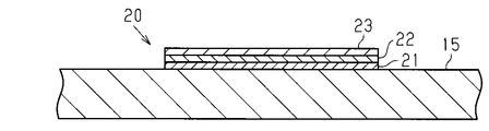
- the stacked body 20 includes a magnetostrictive layer 21, a detection layer 22, and a yoke layer 23, and these layers are sequentially stacked from the plate 15 side.
- the thickness ratio of the plate 15, the magnetostrictive layer 21, the detection layer 22, and the yoke layer 23 is simply illustrated, and the actual thickness ratio is not limited to this.
- the magnetostrictive layer 21 is made of a magnetostrictive material whose magnetization direction changes when stress is received.
- the magnetostrictive material include, for example, a rare earth-transition metal alloy containing a rare earth element and a transition metal element, a transition metal alloy containing a plurality of transition metal elements, and the composition of the magnetostrictive material is not particularly limited.
- the magnetostrictive layer 21 is formed on the first surface 18 of the plate 15 by various film forming processes. The film formation process may be determined according to the type of film formation source. For example, a vacuum deposition method, a sputtering method, an ion plating method, or the like can be used.
- the magnetostrictive layer 21 moves in the circumferential direction of the plate 15 along with the distortion of the plate 15. And a compressive stress along the radial direction of the plate 15. Since the long holes 19 are formed on both sides of each stacked body 20, the stress from the region excluding the small regions 25 is applied to the small regions 25 (see FIG. 2) sandwiched by the long holes 19 in the plate 15. Difficult to communicate. Therefore, the strain of the small region 25 sandwiched by the long holes 19 can be transmitted to the magnetostrictive layer 21 while eliminating the influence of stress from the region other than the small region 25 as much as possible.
- any slit having any shape can be used as long as it can transmit the strain of the small region 25 to the magnetostrictive layer 21 while eliminating the influence of the stress from the region other than the region 25 directly on the small region 25 as much as possible. I do not care.
- the detection layer 22 is a layer that detects a change in the direction of magnetization generated by the strain of the magnetostrictive layer 21 and includes, for example, a detection coil.
- the detection coil is, for example, a metal pattern formed on the surface of the substrate, or a metal pattern exposed on the surface of the substrate by etching or the like.
- the detection coil is connected to a detection circuit that inputs an electrical signal output from the detection coil.
- the detection circuit detects, for example, the magnitude of the induced voltage as the amount of change in pressure.
- the yoke layer 23 is for exciting the magnetic flux of the magnetostrictive layer 21.
- the direction of magnetization (magnetic flux) of the magnetostrictive layer 21 changes and a voltage is induced in the detection layer 22.
- the detection layer 22 outputs an electrical signal corresponding to the induced voltage to the detection circuit.
- the detection circuit calculates the pressure in the cylinder 11 based on the electrical signal input from the stacked body 20.
- the detection circuit calculates the pressure in the cylinder 11 based on the electrical signal input from the stacked body 20.
- the magnetostrictive layer 21 is provided on the surface of the plate 15 parallel to the radial direction R of the cylinder 11, that is, the plane orthogonal to the axis of the cylinder 11, magnetostriction is caused by expansion and contraction of the cylinder 11.
- the layer 21 is subjected to tensile stress along the circumferential direction ⁇ and compressive stress along the radial direction R.
- the stress in the direction parallel to the radial direction R that is, the direction orthogonal to the axis of the cylindrical body 11
- the change in the direction of magnetization is mainly compared to the case where only the tensile stress acts on the magnetostrictive layer 21.
- the magnetostrictive layer 21 is provided on a part of the plate 15 made of an elastic body, the magnetostrictive material can be made the minimum necessary amount required for detecting the pressure.
- the pressure sensor has a configuration in which the magnetostrictive layer 21 is formed on the first surface 18 which is a flat surface, the degree of freedom in the manufacturing process can be increased. Since the material of the plate 15 should just be a material which has an elasticity and heat resistance at least, the freedom degree of material can also be raised.
- the detection layer 22 is laminated between the magnetostrictive layer 21 and the yoke layer 23, for example, the detection layer 22 is easier to assemble than a configuration in which a detection coil is wound around a magnetostrictive material. As described above, according to the present embodiment, the following effects can be obtained.
- the magnetostrictive layer 21 made of a magnetostrictive material is provided on a part of the plate 15 that is an elastic body that is in contact with the cylindrical body 11, the use amount of the magnetostrictive material is reduced as compared with a sensor in which the plate 15 is made of a magnetostrictive material. Can be achieved.
- the magnetostrictive layer 21 is provided on a part of the first surface 18 along the radial direction of the cylindrical body 11 in the plate 15, the use of the magnetostrictive material is used as compared with the sensor that forms the entire plate 15 from the magnetostrictive material. The amount can be reduced.
- the cylinder 30 provided in the pressure sensor has the same configuration as that of the first embodiment, but the cylinder of the first embodiment is that the outer shape of the cross section is circular. Different from the body 11. Exhaust gas flowing in from the inlet 33 of the cylinder 30 flows inside the cylinder 30. A wire 31 made of a magnetostrictive material is wound around the cylindrical body 30. A region 32 of the cylindrical body 30 around which the wire 31 is wound is a part of the outer peripheral surface of the cylindrical body 30 in the axial direction Z, and the wire 31 is spirally wound with a gap.
- the wire 31 is wound in contact with the outer peripheral surface of the cylindrical body 30, and is deformed in the same direction as the cylindrical body 30 with the radial deformation (distortion) of the cylindrical body 30.
- the wire 31 receives a tensile stress at least in the circumferential direction ⁇ of the cylindrical body 30, and the magnetization direction of the linear material 31 changes.
- a detection unit 35 is provided outside the cylindrical body 30 and in the vicinity of the outer peripheral surface thereof.
- the detection unit 35 is, for example, a metal pattern formed on the surface of the substrate, or a metal pattern exposed on the surface of the substrate by etching or the like, and corresponds to the detection layer 22 of the first embodiment. .
- the detection unit 35 may use a Hall element, a Gauss meter using the Hall element, a pickup coil, or the like.
- the detection unit 35 is connected to a detection circuit that detects the magnitude of the output voltage from the detection unit 35 and the like.
- the operation of the pressure sensor will be described with reference to FIG.
- the inner peripheral surface of the cylinder 30 receives pressure in the direction indicated by the solid line arrow in FIG. Distorted.
- a change in the direction of magnetization (magnetic flux) occurs in the wire 31
- a voltage is induced in the detection unit 35, and an electrical signal corresponding to the induced voltage is output to the detection circuit.
- the detection circuit calculates the pressure in the cylinder 30 based on the electrical signal input from the detection unit 35.
- the detection circuit calculates the pressure in the cylinder 30 based on the electrical signal input from the detection unit 35.
- the magnetostriction can be adjusted by adjusting the number of turns and the interval of the wire 31.
- the amount of material used can be made the minimum necessary amount.
- the pressure of the cylindrical body 30 is higher than that of a pressure sensor having a configuration in which another member made of an elastic body is interposed between the cylindrical body 30 and the wire 31.
- the change can be directly transmitted to the wire 31.
- the pressure change of the cylindrical body 30 is indirectly transmitted to the magnetostrictive material, the pressure is measured in a state where the manufacturing error of each member is cumulatively added. By being transmitted directly to the wire 31, an increase in error can be suppressed.
- the magnetostrictive material is provided in a part of the cylindrical body 30, it is possible to reduce the amount of the magnetostrictive material used compared to a sensor in which the elastic body pressed by the deformation of the cylindrical body 30 is configured from the magnetostrictive material. it can.
- the cylinder 30 of the pressure sensor has the same configuration as that of the second embodiment.
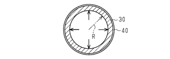
- a thin film 40 made of a magnetostrictive material is formed on the outer peripheral surface of the cylindrical body 30.
- a region 41 where the thin film 40 is formed in the cylindrical body 30 is a part of the outer peripheral surface of the cylindrical body 30 in the axial direction Z.
- the thin film 40 is provided on the entire circumference in the circumferential direction of the outer circumferential surface of the cylindrical body 30.
- the thin film 40 may be formed on the flat substrate before being formed into the cylindrical body 30 by various film forming processes, and various film forming processes are performed on the cylindrical body 30 that has been previously cylindrically formed. It may be formed by.
- a vacuum deposition method, a sputtering method, an ion plating method, or the like can be used as the film forming process.
- a detection unit 35 is provided outside the cylindrical body 30 and in the vicinity of the outer peripheral surface thereof.
- the detection unit 35 has the same configuration as the detection unit 35 of the second embodiment.
- the operation of the pressure sensor will be described with reference to FIG.
- the inner peripheral surface of the cylinder 30 receives pressure in the direction indicated by the solid line arrow in FIG. 10 as the pressure in the exhaust passage increases, the thin film 30 expands in a direction parallel to the radial direction R. 40 also expands and strains in the same direction, and a tensile stress is generated in the thin film 40 along the circumferential direction ⁇ (see FIG. 9) of the cylindrical body 30.
- the detection circuit calculates the pressure in the cylinder 30 based on the electrical signal input from the detection unit 35.
- the cylindrical body 30 contracts in the radial direction R. Thereby, since the tensile stress along the circumferential direction ⁇ received by the thin film 40 is reduced, the direction of magnetization (magnetic flux) of the magnetostrictive layer 21 of the magnetostrictive layer 21 is changed contrary to when the cylindrical body 30 is expanded.
- the detection circuit calculates the pressure in the cylinder 30 based on the electrical signal input from the detection unit 35.
- the thin film 40 is formed on the outer surface of the cylindrical body 30, it is easy to adjust the thickness of the magnetostrictive material to a suitable thickness. For this reason, it is possible to minimize the amount of the magnetostrictive material used rather than using a magnetostrictive material made of sheet metal, for example. Further, since the thin film 40 is formed on a part of the outer surface of the cylindrical body 30 in the axial direction Z, the amount used can be reduced as compared with the case where it is formed in the entire area in the axial direction Z.
- the pressure change of the cylindrical body 30 is reduced as compared with the configuration in which another member made of an elastic body is interposed between the cylindrical body 30 and the thin film 40. 40 can be communicated directly.
- the pressure change of the cylindrical body 30 is indirectly transmitted to the magnetostrictive material, the pressure is measured in a state where the manufacturing error of each member is cumulatively added. By being transmitted directly to the thin film 40, it is possible to suppress an increase in error.
- the effect (3) is obtained, and the following effects are further obtained.
- the thin film 40 provided on the outer peripheral surface of the cylindrical body 30 is also distorted by the change of the outer diameter of the cylindrical body 30 with the change of the pressure in the exhaust passage. For this reason, it is possible to detect a change in pressure based on a change in the direction of magnetization accompanying the distortion of the thin film 40.
- the thin film 40 can be easily adjusted to a suitable thickness for detecting pressure, the amount of magnetostrictive material used can be reduced by making it as thin as possible.
- each said embodiment can also be implemented with the following forms.
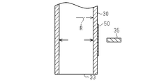
- the thin film 50 formed in a part of the circumferential direction of the cylinder 30.
- the thin film 50 is curved along the outer peripheral surface of the cylindrical body 30.
- the thin film 50 when the cylindrical body 30 expands, the thin film 50 also receives a tensile stress in the circumferential direction, so that the magnetization direction of the thin film 50 changes.
- the thin film 50 since the area where the thin film 50 is formed can be reduced in the axial direction and the circumferential direction of the cylindrical body 30, the amount of magnetostrictive material used can be reduced.
- the thin film 50 may be a sheet metal made of a magnetostrictive material instead of being formed by various film forming processes.
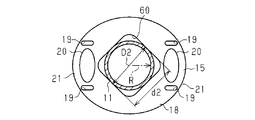
- a rectangular through hole 60 may be used instead of the through hole 16. Moreover, you may make it the cylinder 11 contact the internal peripheral surface of the through-hole 60 in the four places.
- the outer diameter D2 of the cylindrical body 11 is equal to the inner diameter d2 of the through hole 60 that is the length of one side of the square. Same or slightly larger.
- the magnetostrictive layer 21 is formed on the plate 15 by various film forming processes such as vacuum deposition and sputtering, but may be formed by other methods.
- the magnetostrictive layer 21 and the detection layer 22 of the laminate 20 may be formed on a caulking base 63.
- the pedestal 63 is provided with a protruding piece 64 protruding outward.
- the plate 15 is formed with a recess 61 that can accommodate the pedestal 63 including the projecting piece 64, and the recess 61 is provided with a claw portion 62 that prevents the pedestal 63 from falling off.
- the claw portion 62 When the laminated body 20 is fixed to the plate 15, the claw portion 62 is opened to the outside, the pedestal 63 is fitted into the concave portion 61 of the plate 15, and then the pedestal 63 is crimped by tilting the claw portion 62 inward.
- the laminate 20 may be crimped to the plate 15 by other methods.
- the pair of long holes 19 are formed on both sides of the stacked body 20, but it is only necessary to be easily subjected to stress in the small region 25 where the stacked body 20 is formed. There may be. Further, even if the plate 15 does not have the long hole 19, the long hole 19 may be omitted if the change in magnetization of the magnetostrictive layer 21 subjected to tensile stress can be detected.
- FIG. 14 shows an example in which the detection coil 65 is provided in the pressure sensor in which the thin film 40 is formed on the outer peripheral surface of the cylindrical body 30.
- the detection coil 65 is used, a change in magnetic permeability accompanying deformation of the thin film 40 (or wire 31) made of a magnetostrictive material can be detected as a change in inductance of the detection coil 65.
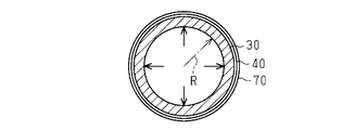
- the yoke layer 70 may be laminated on the thin film 40 in the pressure sensor of the third embodiment in which the thin film 40 is formed on the cylindrical body 30.
- the laminated body 20 of 1st Embodiment may be the structure which abbreviate
- the detection layer 22 may be omitted from the stacked body 20 by providing the detection unit 35 separately.
- an excitation yoke may be provided outside the wire 31.
- the pressure sensor is used as a sensor for detecting the pressure in the exhaust passage, but the application and measurement target of the pressure sensor are not particularly limited.
- the measurement target may be a fluid, and may be, for example, a liquid, a sol, or a solid melt.
- the pressure sensor may be provided in a moving body such as a vehicle or a ship, or may be provided in a device installed at a predetermined place, or may be portable.
Landscapes
- Physics & Mathematics (AREA)
- General Physics & Mathematics (AREA)
- Measuring Fluid Pressure (AREA)
Abstract
圧力センサは、内側を流れる流体の圧力で変形する筒体(11)と、筒体(11)と接触し筒体(11)の変形に伴い押圧されるプレート(15)の一部に設けられ、筒体(11)の変形に伴って歪む磁歪材(20)とを備える。
Description
本発明は、磁歪式の圧力センサに関する。
磁歪式の圧力センサは、磁歪材の歪みによって磁歪材の磁化の方向が変化する逆磁歪効果を利用するセンサである。磁歪式の圧力センサとしては、パーマロイなどの強磁性材からなる薄肉板に、励磁用コイルと、出力用コイルとを直交させて巻回したものがある(例えば、特許文献1参照)。流体の圧力変化によって薄肉板に力が作用すると、励磁コイルの磁束分布が変化して出力コイルに電圧が誘起される。そして、この誘起電圧が圧力の変化量として検出される。
しかし、上記センサは、薄肉板全体が磁歪材からなる構成であるため、圧力センサを製造するにあたり使用される磁歪材の量が必然的に多くなる。そのため、磁歪材の使用量を低減する観点からは、なお改善の余地を残すこととなっていた。
本発明は、上記実情を鑑みてなされたものであり、その目的は、磁歪材の使用量を低減することができる圧力センサを提供することにある。
以下、上記課題を解決するための手段及びその作用効果について記載する。
上記課題を解決する本発明の一態様の圧力センサは、内側を流れる流体の圧力で変形する筒体と、前記筒体と接触し前記筒体の変形に伴い押圧される弾性体の一部、又は前記筒体の一部に設けられ、前記筒体の変形に伴って歪む磁歪材と、を備えることを要旨とする。
上記課題を解決する本発明の一態様の圧力センサは、内側を流れる流体の圧力で変形する筒体と、前記筒体と接触し前記筒体の変形に伴い押圧される弾性体の一部、又は前記筒体の一部に設けられ、前記筒体の変形に伴って歪む磁歪材と、を備えることを要旨とする。
上記構成によれば、筒体の一部、又は筒体と接触する弾性体の一部に磁歪材が設けられるため、弾性体を磁歪材から構成するセンサに比べ、磁歪材の使用量の低減を図ることができる。
上記圧力センサについて、前記筒体の変形に伴い押圧される弾性体は、当該弾性体に形成された孔部の内周面において前記筒体の外周面と接触するとともに、前記磁歪材は、前記弾性体のうち、前記筒体の径方向に沿った面、すなわち筒体の軸線と直交する面の一部に設けられることが好ましい。
上記構成によれば、筒体の内側を流れる流体の圧力で筒体の外径が変化することによって、筒体と接触する弾性体が歪むと、弾性体のうち筒体の径方向に沿った面に設けられた磁歪材は、引っ張り応力と径方向に平行な方向の応力とを受ける。このため、磁歪材の応力に伴う磁界の変化に基づき圧力の変化を検出することが可能となる。また、弾性体のうち、筒体の径方向に沿った面の一部に磁歪材が設けられるため、弾性体全体を磁歪材から形成するセンサに比べ、磁歪材の使用量の低減を図ることができる。
上記圧力センサについて、前記弾性体のうち、前記磁歪材が設けられた領域と、当該領域を除く領域とは、前記弾性体に設けられたスリットによって一部分離されていることが好ましい。
上記構成によれば、弾性体の磁歪材が設けられた領域とその領域を除く領域、すなわち磁歪材が設けられていない弾性体の領域とは、スリットによって一部分離されているので、磁歪材が設けられていない領域からの応力が、磁歪材が設けられた領域に直接影響することを抑制しつつ、磁歪材が設けられた領域の歪みを磁歪材に伝えることができる。
上記圧力センサについて、前記磁歪材が設けられた領域と当該領域を除く領域とを一部分離する前記スリットは、長孔であることが好ましい。
上記構成によれば、磁歪材が設けられた領域と、当該領域とを除く領域とを一部分離するスリットの加工を容易に行うことができる。
上記構成によれば、磁歪材が設けられた領域と、当該領域とを除く領域とを一部分離するスリットの加工を容易に行うことができる。
上記圧力センサについて、前記磁歪材は、前記筒体の外周面のうち、前記筒体の軸方向における一部の範囲に巻かれる線材であることが好ましい。
上記構成によれば、流体の圧力が変化すると、筒体の外径が変化することによって、筒体の外周面に巻かれた線材も歪む。このため、磁歪材の歪みに伴う磁場の変化に基づき流体の圧力の変化を検出することが可能となる。また、筒体の軸方向における一部の範囲に磁歪材からなる線材が巻かれるため、磁歪材の使用量の低減を図ることができる。
上記構成によれば、流体の圧力が変化すると、筒体の外径が変化することによって、筒体の外周面に巻かれた線材も歪む。このため、磁歪材の歪みに伴う磁場の変化に基づき流体の圧力の変化を検出することが可能となる。また、筒体の軸方向における一部の範囲に磁歪材からなる線材が巻かれるため、磁歪材の使用量の低減を図ることができる。
上記圧力センサについて、前記磁歪材は、前記筒体の外周面に形成された薄膜であることが好ましい。
上記構成によれば、流体の圧力が変化すると、筒体の外径が変化することによって、筒体の外周面に設けられた薄膜状の磁歪材も歪む。このため、磁歪材の歪みに伴う磁場の変化に基づき流体の圧力の変化を検出することが可能となる。また、磁歪材は外周面に形成された薄膜であって、磁歪材が金属板などである場合に比べ薄膜化することが可能であるため、磁歪材の使用量の低減を図ることができる。
上記構成によれば、流体の圧力が変化すると、筒体の外径が変化することによって、筒体の外周面に設けられた薄膜状の磁歪材も歪む。このため、磁歪材の歪みに伴う磁場の変化に基づき流体の圧力の変化を検出することが可能となる。また、磁歪材は外周面に形成された薄膜であって、磁歪材が金属板などである場合に比べ薄膜化することが可能であるため、磁歪材の使用量の低減を図ることができる。
上記圧力センサについて、前記磁歪材は、前記筒体の外周面に沿って湾曲するとともに当該外周面の周方向における一部に設けられることが好ましい。
上記構成によれば、流体の圧力が変化すると、筒体の外径が変化することによって、筒体の外周面に湾曲した状態で設けられた磁歪材が歪む。このため、磁歪材の歪みに伴う磁場の変化などに基づき流体の圧力の変化を検出することが可能となる。また、筒体の周方向における一部に磁歪材が設けられるため、磁歪材の使用量の低減を図ることができる。
上記構成によれば、流体の圧力が変化すると、筒体の外径が変化することによって、筒体の外周面に湾曲した状態で設けられた磁歪材が歪む。このため、磁歪材の歪みに伴う磁場の変化などに基づき流体の圧力の変化を検出することが可能となる。また、筒体の周方向における一部に磁歪材が設けられるため、磁歪材の使用量の低減を図ることができる。
本発明によれば、磁歪材の使用量を低減することができる。
本発明の他の態様及び利点は、本発明の技術的思想の例を示す図面と共に以下の記載から明らかとなる。
本発明の他の態様及び利点は、本発明の技術的思想の例を示す図面と共に以下の記載から明らかとなる。
(第1の実施形態)
以下、図1~図4を参照して、本発明の第1の実施形態の圧力センサについて説明する。本実施形態の圧力センサは、エンジンの排気通路内の圧力を検出するセンサとして用いられる。圧力センサは、排気通路に設けられるか、又は排気通路に接続する流路に設けられる。
以下、図1~図4を参照して、本発明の第1の実施形態の圧力センサについて説明する。本実施形態の圧力センサは、エンジンの排気通路内の圧力を検出するセンサとして用いられる。圧力センサは、排気通路に設けられるか、又は排気通路に接続する流路に設けられる。
図1に示すように、圧力センサは、筒体11を備えている。筒体11は、その一方の端部に、排気通路内の排気ガスが導入される導入口12を備えている。導入口12から導入された排気ガスは、筒体11の内側を流れる。筒体11の他方の端部は、閉塞されているか、又は別の配管に接続されている。筒体11が別の配管に接続される場合は、当該配管のうち、筒体11と接続される端部とは反対側の端部が閉塞される。排気通路内の圧力が上昇した場合には、筒体11内の圧力も上昇し、排気通路内の圧力が低下した場合には、筒体11内の圧力も低下する。
筒体11の周壁部13は、筒体11の内側の半径よりも小さい厚さを有している。また、筒体11を構成する材料は、弾性を有するとともに、測定対象の流体(ここでは排気ガス)に対する耐熱性および耐食性を有する材料であればよい。筒体11は、排気通路内の圧力変化に伴い、その径方向Rと平行な方向、すなわち筒体11の軸線と直交する方向に変形する。すなわち、排気通路内の圧力が上昇すると、筒体11は径方向Rに膨張する。また、排気通路内の圧力が上昇から下降に転じると、膨張した筒体11は収縮して標準状態に戻る。なお、筒体11の径方向Rとは、筒体11の中心軸から周壁部13に放射状に向かう方向であり、中心軸から周壁部13の内周面の一点に向かう一つの方向を指すものではない。
図2に示すように、筒体11は、径方向Rと平行な断面の外形形状が楕円形である。筒体11は、弾性体であるプレート15に貫挿されている。プレート15は、円盤状に形成されるとともに、筒体11から伝わる排気ガス由来の熱に対する耐熱性を備える材料からなる弾性体であり、例えば金属から形成される。プレート15の中央部には、円形状又は楕円形状の貫通孔16が形成されている。プレート15の外側の縁から貫通孔16の縁までの幅Wは、プレート15の厚さよりも大きい。
筒体11は、その外周面の2箇所においてプレート15の貫通孔16の内周面と接触している。筒体11が貫通孔16の内周面と接触する接触部17は、筒体11の楕円状の断面の長軸上にあり、各接触部17は筒体11の中心軸に対して対称である。筒体11の接触部17の間の外径D1は、貫通孔16の内径d1と同じか、それよりもわずかに大きい。排気通路内の圧力の上昇に伴い筒体11が膨張するとき、筒体11は接触部17を介してプレート15を押圧する。
プレート15のうち、筒体11の径方向Rと平行な面、すなわち筒体11の軸線と直交する面である第1の面18には、1対の積層体20が設けられている。積層体20は、磁歪層を含む複数の層が積層されて形成されている。積層体20は、第1の面18のうち、貫通孔16を挟んだ両側であって、筒体11の接触部17を結んだ直線L1上に設けられている。積層体20は、第1の面18側からみて円形状又は楕円形状に形成されているが、矩形状であってもよい。また、プレート15には、各積層体20に対して1対の長孔19が貫通形成されている。1対の長孔19は、直線L1を挟んだ両側にそれぞれ設けられている。
次に、図3を参照して積層体20について説明する。積層体20は、磁歪層21、検出層22、およびヨーク層23を備え、これらの層はプレート15側から順に積層されている。なお、図3では、プレート15、磁歪層21、検出層22およびヨーク層23の厚さの比率を簡易的に図示しており、実際の厚さの比率はこれに限定されない。
磁歪層21は、応力を受けることによって磁化の方向が変化する磁歪材からなる。磁歪材の例としては、例えば、希土類元素と遷移金属元素とを含む希土類‐遷移金属系合金、複数の遷移金属元素を含む遷移金属系合金などが挙げられるが、磁歪材の組成は特に限定されない。また、磁歪層21は、プレート15の第1の面18に各種の成膜プロセスによって形成されている。成膜プロセスは、成膜源の種類に応じて決定すればよく、例えば、真空蒸着法、スパッタ法、イオンブレーティング法などを用いることができる。
排気通路内の圧力の上昇に伴い筒体11が膨張し、筒体11が接触部17を介してプレート15を押圧するとき、プレート15の歪みに伴い、磁歪層21は、プレート15の周方向に沿った引っ張り応力と、プレート15の径方向に沿った圧縮応力とを受ける。各積層体20の両側には長孔19が形成されているため、プレート15のうち長孔19によって挟まれた小領域25(図2参照)には、小領域25を除く領域からの応力が伝わりにくい。このため、小領域25を除く領域からの応力の影響を極力排除しつつ、長孔19によって挟まれた小領域25の歪みを磁歪層21に伝えることができる。尚、小領域25と小領域25を除く領域とが長孔19によって一部分離されている例を示したが、長孔19の代わりに矩形や楕円その他の形状のスリットであってもよく、小領域25を除く領域からの応力の影響が直接小領域25に影響するのを極力排除しつつ、小領域25の歪みを磁歪層21に伝えることができれば、どの様な形状のスリットであっても構わない。
検出層22は、磁歪層21の歪みにより発生する磁化の方向の変化を検出する層であって、例えば検出コイルを備える。検出コイルは、例えば、基板の表面に金属パターンを成膜したもの、又は、エッチングなどによって基板の表面に金属パターンを露出させたものである。また、検出コイルは、検出コイルから出力された電気信号を入力する検出回路に接続されている。磁歪層21が応力を受けて磁化(磁束)の方向が変化すると、検出コイルに電圧が誘起され、検出コイルから誘起電圧に応じた電気信号が検出回路に出力される。検出回路は、例えば誘起電圧の大きさを圧力の変化量として検出する。ヨーク層23は、磁歪層21の磁束を励磁するためのものである。
次に、図4を参照して、圧力センサの作用について説明する。排気通路内の圧力が上昇するに伴い筒体11内の圧力が上昇すると、筒体11の内周面に図4中の実線の矢印で示す方向に圧力が加わり、筒体11が径方向Rに等方的に膨張する。膨張した筒体11は、接触部17を介してプレート15を押圧する。筒体11によってプレート15が押圧されると、プレート15のうち、積層体20が設けられた小領域25は、周方向θ(図2参照)に沿った引っ張り応力を受けるとともに、径方向Rに沿った圧縮応力を受けるため、小領域25に設けられた磁歪層21も周方向θの引っ張り応力および径方向Rの圧縮応力を受ける。これにより、磁歪層21の磁化(磁束)の方向が変化して、検出層22に電圧が誘起される。検出層22は、誘起電圧に応じた電気信号を検出回路に出力する。検出回路は、積層体20から入力した電気信号に基づき、筒体11内の圧力を演算する。
筒体11を膨張させる程度に排気通路内の圧力が上昇した後に、排気通路内の圧力が低下すると、筒体11が収縮する。これにより、磁歪層21が受ける周方向θの引っ張り応力および径方向Rの圧縮応力が小さくなるため、筒体11が膨張したときとは逆に磁歪層21の磁化(磁束)の方向が変化する。検出回路は、積層体20から入力した電気信号に基づき、筒体11内の圧力を演算する。
このように、磁歪層21は、プレート15のうち筒体11の径方向Rと平行な面、すなわち筒体11の軸線と直交する面に設けられるため、筒体11の膨張および収縮によって、磁歪層21は周方向θに沿った引っ張り応力および径方向Rに沿った圧縮応力を受ける。このため、例えば径方向Rと平行な方向(すなわち筒体11の軸線に直交する方向)の応力が極めて小さく、主に磁歪層21に引っ張り応力のみが作用する場合に比べ、磁化の方向の変化を検出しやすくすることができる。また、弾性体からなるプレート15の一部に磁歪層21を設けたので、磁歪材を、圧力を検出するために要する必要最小限の量とすることができる。
さらに、圧力センサは、平面である第1の面18に磁歪層21が形成される構成であるため、製造プロセスの自由度も高めることができる。プレート15の材料は、少なくとも弾性および耐熱性を有する材料であればよいため、材料の自由度を高めることもできる。
さらに検出層22は、磁歪層21とヨーク層23との間に積層されるため、例えば磁歪材に検出用コイルを巻く構成に比べて、組み立てが容易である。
以上説明したように、本実施形態によれば、以下の効果が得られるようになる。
以上説明したように、本実施形態によれば、以下の効果が得られるようになる。
(1)筒体11と接触する弾性体であるプレート15の一部に磁歪材からなる磁歪層21が設けられるため、プレート15を磁歪材から構成するセンサに比べ、磁歪材の使用量の低減を図ることができる。
(2)排気通路内の圧力の変化に伴い筒体11の外径が変化することによって、筒体11と接触するプレート15が歪むと、プレート15のうち筒体11の径方向に沿った第1の面18に設けられた磁歪層21は、プレート15の周方向θに沿った引っ張り応力と径方向Rに沿った圧縮応力とを受ける。このため、磁歪層21の応力に伴う磁化の方向の変化に基づき排気通路内の圧力の変化を検出することが可能となる。また、プレート15のうち、筒体11の径方向に沿った第1の面18の一部に磁歪層21が設けられるため、プレート15全体を磁歪材から形成するセンサに比べ、磁歪材の使用量の低減を図ることができる。
(第2の実施形態)
次に、図5~図7を参照して、本発明の第2の実施形態の圧力センサを説明する。なお、本実施形態にかかる圧力センサも、その基本的な構成は第1の実施形態と同等であり、重複する説明は割愛する。
次に、図5~図7を参照して、本発明の第2の実施形態の圧力センサを説明する。なお、本実施形態にかかる圧力センサも、その基本的な構成は第1の実施形態と同等であり、重複する説明は割愛する。
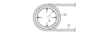
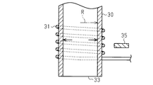
図5に示すように、圧力センサに設けられた筒体30は、第1の実施形態と同様の構成であるが、断面の外形の形状が円形状である点で第1の実施形態の筒体11と異なる。筒体30の導入口33から流入した排気ガスは、筒体30の内側を流れる。また、筒体30には、磁歪材からなる線材31が巻き付けられている。筒体30のうち線材31が巻き付けられた領域32は、筒体30の外周面の軸方向Zにおける一部であって、線材31は、間隔を設けて螺旋状に巻き付けられている。
図6に示すように、線材31は、筒体30の外周面に接触させて巻き付けられており、筒体30の径方向の変形(歪み)に伴い、筒体30と同じ方向に変形する。例えば、筒体30が径方向Rに膨張すると、線材31が少なくとも筒体30の周方向θに引っ張り応力を受けて、線材31の磁化の方向が変化する。
図7に示すように、筒体30の外側であって、その外周面の近傍には、検出部35が設けられている。検出部35は、例えば、基板の表面に金属パターンを成膜したもの、又は、エッチングなどによって基板の表面に金属パターンを露出させたものであり、第1の実施形態の検出層22に相当する。又は、検出部35は、ホール素子や、ホール素子を用いたガウスメータや、ピックアップコイル等を用いてもよい。検出部35は、検出部35からの出力電圧の大きさなどを検出する検出回路に接続されている。
次に、図7を参照して圧力センサの作用について説明する。排気通路内の圧力の上昇に伴い、筒体30の内周面が図7中の実線の矢印で示す方向の圧力を受けて、筒体30が径方向Rに膨張すると、線材31も同方向に歪む。線材31に磁化(磁束)の方向の変化が生じると、検出部35には電圧が誘起され、検出回路に誘起電圧に応じた電気信号が出力される。検出回路は、検出部35から入力した電気信号に基づき、筒体30内の圧力を演算する。
筒体30を膨張させる程度に排気通路内の圧力が上昇した後に、排気通路内の圧力が低下すると、筒体30が収縮する。これにより、線材31が受ける周方向θ(図6参照)の引っ張り応力が小さくなるため、筒体30が膨張したときとは逆に磁歪層21の磁歪層21の磁化(磁束)の方向が変化する。検出回路は、検出部35から入力した電気信号に基づき、筒体30内の圧力を演算する。
このように、筒体30の外表面のうち軸方向Zの一部に、間隔を設けて線材31を螺旋状に巻きつけたので、線材31の巻き数や間隔などを調整することで、磁歪材が使用される量を必要最小限の量とすることができる。
また、筒体30の径方向Rにおける変形により線材31が歪むため、筒体30と線材31との間に弾性体からなる別の部材を介在させる構成の圧力センサに比べ、筒体30の圧力変化を線材31に直接的に伝えることが可能となる。筒体30の圧力変化が間接的に磁歪材に伝えられると、各部材の製造上の誤差などが累積的に加味された状態で圧力が測定されることとなるが、筒体30の圧力が線材31に直接的に伝わることで、誤差が大きくなることを抑制することができる。
以上説明したように、本実施形態によれば、以下の効果が得られるようになる。
(3)筒体30の一部に磁歪材が設けられるため、筒体30の変形に伴い押圧される弾性体を磁歪材から構成するセンサに比べ、磁歪材の使用量の低減を図ることができる。
(3)筒体30の一部に磁歪材が設けられるため、筒体30の変形に伴い押圧される弾性体を磁歪材から構成するセンサに比べ、磁歪材の使用量の低減を図ることができる。
(4)排気通路内の圧力変化に伴い筒体30の外径が変化することによって、筒体30の外周面に巻かれた線材31も歪む。このため、線材31の歪みに伴う磁化の方向の変化に基づき圧力の変化を検出することが可能となる。また、筒体30の軸方向Zにおける一部の範囲に線材31が巻かれるため、磁歪材の使用量の低減を図ることができる。
(第3の実施形態)
次に、図8~図10を参照して、圧力センサの第3の実施形態を説明する。なお、本実施の形態にかかる圧力センサも、その基本的な構成は第1の実施形態および第2の実施形態と同等であり、重複する説明は割愛する。
次に、図8~図10を参照して、圧力センサの第3の実施形態を説明する。なお、本実施の形態にかかる圧力センサも、その基本的な構成は第1の実施形態および第2の実施形態と同等であり、重複する説明は割愛する。
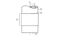
図8に示すように、圧力センサの筒体30は、第2の実施形態と同様の構成である。筒体30の外周面には、磁歪材からなる薄膜40が形成されている。筒体30のうち薄膜40が形成された領域41は、筒体30の外周面のうち軸方向Zにおける一部である。
図9に示すように、薄膜40は、筒体30の外周面の周方向における全周に設けられている。薄膜40は、筒体30に成形される前の平板状の基材に各種の成膜プロセスによって形成されるものであってもよく、予め筒状にされた筒体30に各種の成膜プロセスによって形成されるものであってもよい。成膜プロセスは、例えば、真空蒸着法、スパッタ法、イオンブレーティング法などを用いることができる。
図10に示すように、筒体30の外側であって、その外周面の近傍には、検出部35が設けられている。検出部35は、第2の実施形態の検出部35と同じ構成のものである。
次に、図10を参照して圧力センサの作用について説明する。排気通路内の圧力の上昇に伴い、筒体30の内周面が図10中の実線の矢印で示す方向の圧力を受けて、筒体30が径方向Rと平行な方向に膨張すると、薄膜40も同じ方向に膨張して歪み、薄膜40には筒体30の周方向θ(図9参照)に沿った引っ張り応力が発生する。薄膜40に磁化(磁束)の方向の変化が生じると、検出部35には電圧が誘起され、検出回路に誘起電圧に応じた電気信号が出力される。検出回路は、検出部35から入力した電気信号に基づき、筒体30内の圧力を演算する。
次に、図10を参照して圧力センサの作用について説明する。排気通路内の圧力の上昇に伴い、筒体30の内周面が図10中の実線の矢印で示す方向の圧力を受けて、筒体30が径方向Rと平行な方向に膨張すると、薄膜40も同じ方向に膨張して歪み、薄膜40には筒体30の周方向θ(図9参照)に沿った引っ張り応力が発生する。薄膜40に磁化(磁束)の方向の変化が生じると、検出部35には電圧が誘起され、検出回路に誘起電圧に応じた電気信号が出力される。検出回路は、検出部35から入力した電気信号に基づき、筒体30内の圧力を演算する。
筒体30を膨張させる程度に排気通路内の圧力が上昇した後に、排気通路内の圧力が低下すると、筒体30が径方向Rにおいて収縮する。これにより、薄膜40が受ける周方向θに沿った引っ張り応力が小さくなるため、筒体30が膨張したときとは逆に磁歪層21の磁歪層21の磁化(磁束)の方向が変化する。検出回路は、検出部35から入力した電気信号に基づき、筒体30内の圧力を演算する。
このように、筒体30の外表面に薄膜40を形成したので、磁歪材の厚さを好適な厚さに調整することが容易である。このため、例えば板金からなる磁歪材を使用するよりも磁歪材が使用される量を必要最小限とすることが可能となる。また、薄膜40は、筒体30の外表面のうち、軸方向Zの一部に形成したので、軸方向Zの全域に形成する場合に比べ、使用される量を少なくすることができる。
また、筒体30の径方向Rにおける変形により薄膜40が歪むため、筒体30と薄膜40との間に弾性体からなる別の部材を介在させる構成に比べ、筒体30の圧力変化を薄膜40に直接的に伝えることが可能となる。筒体30の圧力変化が間接的に磁歪材に伝えられると、各部材の製造上の誤差などが累積的に加味された状態で圧力が測定されることとなるが、筒体30の圧力が薄膜40に直接的に伝わることで、誤差が大きくなることを抑制することができる。
以上説明したように、本実施形態によれば、上記(3)の効果が得られるとともに、さらに以下の効果が得られるようになる。
(5)排気通路内の圧力の変化に伴い筒体30の外径が変化することによって、筒体30の外周面に設けられた薄膜40も歪む。このため、薄膜40の歪みに伴う磁化の方向の変化に基づき圧力の変化を検出することが可能となる。また、薄膜40は、圧力を検出するための好適な厚さに容易に調整することが可能であるため、極力薄くすることによって磁歪材の使用量の低減を図ることができる。
(5)排気通路内の圧力の変化に伴い筒体30の外径が変化することによって、筒体30の外周面に設けられた薄膜40も歪む。このため、薄膜40の歪みに伴う磁化の方向の変化に基づき圧力の変化を検出することが可能となる。また、薄膜40は、圧力を検出するための好適な厚さに容易に調整することが可能であるため、極力薄くすることによって磁歪材の使用量の低減を図ることができる。
(他の実施の形態)
なお、上記各実施の形態は、以下のような形態をもって実施することもできる。
・第3の実施形態における薄膜40に代えて、図11に示すように、筒体30の周方向の一部に形成された薄膜50としてもよい。薄膜50は、筒体30の外周面に沿って湾曲している。この態様においても、筒体30が膨張するとき、薄膜50も周方向の引っ張り応力を受けるため、薄膜50の磁化の方向が変化する。この態様によれば、薄膜50が形成される面積を筒体30の軸方向および周方向に小さくすることができるので、磁歪材の使用量の低減を図ることができる。なお、この態様において、薄膜50は、各種の成膜プロセスによって形成される代わりに、磁歪材からなる板金であってもよい。
なお、上記各実施の形態は、以下のような形態をもって実施することもできる。
・第3の実施形態における薄膜40に代えて、図11に示すように、筒体30の周方向の一部に形成された薄膜50としてもよい。薄膜50は、筒体30の外周面に沿って湾曲している。この態様においても、筒体30が膨張するとき、薄膜50も周方向の引っ張り応力を受けるため、薄膜50の磁化の方向が変化する。この態様によれば、薄膜50が形成される面積を筒体30の軸方向および周方向に小さくすることができるので、磁歪材の使用量の低減を図ることができる。なお、この態様において、薄膜50は、各種の成膜プロセスによって形成される代わりに、磁歪材からなる板金であってもよい。
・図12に示すように、筒体11をプレート15の貫通孔16に挿通する第1の実施形態の圧力センサにおいて、貫通孔16に代えて、矩形状の貫通孔60としてもよい。また、筒体11は、その4箇所において、貫通孔60の内周面と接触するようにしてもよい。例えば、筒体11の断面の外形形状が円形状であって貫通孔60が正方形状であるとき、筒体11の外径D2は、正方形の一辺の長さである貫通孔60の内径d2と同じか、それよりも僅かに大きい。
・第1の実施形態では、プレート15に磁歪層21を、真空蒸着法やスパッタ法などの各種の成膜プロセスにより形成したが、その他の方法により形成してもよい。例えば、図13に示すように、積層体20の磁歪層21および検出層22を加締め用の台座63に形成してもよい。台座63には、外側に突出した突片64が設けられている。プレート15には、突片64を含めた台座63を収容可能な凹部61が形成され、凹部61には、台座63の脱落を防止する爪部62が設けられている。積層体20をプレート15に固定する際には、爪部62を外側に開いてプレート15の凹部61に台座63を嵌合した上で、爪部62を内側に倒して台座63を加締める。なお、積層体20は、これ以外の方法によってプレート15に加締めるようにしてもよい。
・第1の実施形態では、積層体20の両側に1対の長孔19を形成したが、積層体20が形成された小領域25において応力を受けやすくなればよく、長孔以外のスリットであってもよい。また、長孔19がないプレート15であっても、引っ張り応力を受けた磁歪層21の磁化の変化を検出可能である場合には、長孔19を省略してもよい。
・図14に示すように、筒体30の外周面に線材31を巻き付けた圧力センサ、または筒体30の外周面に磁歪材からなる薄膜40が形成された圧力センサにおいて、検出部35の代わりに、筒体30を内側に挿通する検出コイル65を用いてもよい。なお、図14では、筒体30の外周面に薄膜40が形成された圧力センサに検出コイル65を設けた例を示している。検出コイル65を用いる場合、磁歪材からなる薄膜40(又は線材31)の変形に伴う透磁率の変化を、検出コイル65のインダクタンスの変化として検出することもできる。
・図15に示すように、筒体30に薄膜40を形成した第3の実施形態の圧力センサにおいて、薄膜40の上にヨーク層70を積層してもよい。
・第1の実施形態の積層体20は、ヨーク層23を省略した構成であってもよい。また、検出部35を別に設けることによって、積層体20から検出層22を省略してもよい。
・第1の実施形態の積層体20は、ヨーク層23を省略した構成であってもよい。また、検出部35を別に設けることによって、積層体20から検出層22を省略してもよい。
・筒体30に線材31を巻き付けた第2の実施形態の圧力センサにおいて、線材31の外側に励磁用のヨークを設けてもよい。
・上記実施形態では、圧力センサを排気通路内の圧力を検出するセンサとして用いたが、圧力センサの用途や測定対象は特に限定されない。例えば、測定対象は、流体であればよく、例えば、液体や、ゾル、固体の溶融体であってもよい。また、圧力センサは、車両や船舶などの移動体内に設けられてもよいし、所定の場所に設置された装置内に設けられてもよく、持ち運び可能なものであってもよい。
・上記実施形態では、圧力センサを排気通路内の圧力を検出するセンサとして用いたが、圧力センサの用途や測定対象は特に限定されない。例えば、測定対象は、流体であればよく、例えば、液体や、ゾル、固体の溶融体であってもよい。また、圧力センサは、車両や船舶などの移動体内に設けられてもよいし、所定の場所に設置された装置内に設けられてもよく、持ち運び可能なものであってもよい。
本発明は、例示したものに限定されるものではない。例えば、開示した特定の実施形態の全ての特徴が本発明にとって必須であると解釈されるべきでなく、本発明の主題は、開示した特定の実施形態のすべての特徴よりも少ない特徴に存在することがある。
11,30…筒体、12…導入口、13…周壁部、15…プレート、16,60…貫通孔、17…接触部、18…第1の面、19…長孔、20…積層体、21…磁歪層、22…検出層、23,70…ヨーク層、31…線材、35…検出部、40,50…薄膜。
Claims (7)
- 内側を流れる流体の圧力で変形する筒体と、
前記筒体と接触し前記筒体の変形に伴い押圧される弾性体の一部、又は前記筒体の一部に設けられ、前記筒体の変形に伴って歪む磁歪材と、を備える
圧力センサ。 - 前記弾性体は、当該弾性体に形成された孔部の内周面において前記筒体の外周面と接触するとともに、
前記磁歪材は、前記弾性体のうち、前記筒体の径方向に沿った面の一部に設けられる
請求項1に記載の圧力センサ。 - 前記弾性体のうち、前記磁歪材が設けられた領域と、当該領域を除く領域とは、前記弾性体に設けられたスリットによって一部分離されている
請求項2に記載の圧力センサ。 - 前記磁歪材が設けられた領域と当該領域を除く領域とを一部分離する前記スリットは、長孔である
請求項3に記載の圧力センサ。 - 前記磁歪材は、前記筒体の外周面のうち、前記筒体の軸方向における一部の範囲に巻かれる線材である
請求項1に記載の圧力センサ。 - 前記磁歪材は、前記筒体の外周面に形成された薄膜である
請求項1に記載の圧力センサ。 - 前記磁歪材は、前記筒体の外周面に沿って湾曲するとともに当該外周面の周方向における一部に設けられる
請求項1に記載の圧力センサ。
Priority Applications (1)
| Application Number | Priority Date | Filing Date | Title |
|---|---|---|---|
| JP2017508363A JP6286613B2 (ja) | 2015-03-23 | 2016-03-22 | 圧力センサ |
Applications Claiming Priority (2)
| Application Number | Priority Date | Filing Date | Title |
|---|---|---|---|
| JP2015-059881 | 2015-03-23 | ||
| JP2015059881 | 2015-03-23 |
Publications (1)
| Publication Number | Publication Date |
|---|---|
| WO2016152867A1 true WO2016152867A1 (ja) | 2016-09-29 |
Family
ID=56978525
Family Applications (1)
| Application Number | Title | Priority Date | Filing Date |
|---|---|---|---|
| PCT/JP2016/059020 Ceased WO2016152867A1 (ja) | 2015-03-23 | 2016-03-22 | 圧力センサ |
Country Status (2)
| Country | Link |
|---|---|
| JP (1) | JP6286613B2 (ja) |
| WO (1) | WO2016152867A1 (ja) |
Citations (2)
| Publication number | Priority date | Publication date | Assignee | Title |
|---|---|---|---|---|
| JPH0833333B2 (ja) * | 1988-02-04 | 1996-03-29 | 松下電器産業株式会社 | 圧力センサ |
| JP4301423B2 (ja) * | 1998-05-14 | 2009-07-22 | エービービー エービー | 燃焼エンジンのシリンダ内のガス圧力計測用の圧力センサ |
-
2016
- 2016-03-22 WO PCT/JP2016/059020 patent/WO2016152867A1/ja not_active Ceased
- 2016-03-22 JP JP2017508363A patent/JP6286613B2/ja active Active
Patent Citations (2)
| Publication number | Priority date | Publication date | Assignee | Title |
|---|---|---|---|---|
| JPH0833333B2 (ja) * | 1988-02-04 | 1996-03-29 | 松下電器産業株式会社 | 圧力センサ |
| JP4301423B2 (ja) * | 1998-05-14 | 2009-07-22 | エービービー エービー | 燃焼エンジンのシリンダ内のガス圧力計測用の圧力センサ |
Also Published As
| Publication number | Publication date |
|---|---|
| JP6286613B2 (ja) | 2018-02-28 |
| JPWO2016152867A1 (ja) | 2017-12-07 |
Similar Documents
| Publication | Publication Date | Title |
|---|---|---|
| JP5735882B2 (ja) | 磁気式荷重センサ | |
| JP5487402B2 (ja) | 磁気平衡式電流センサ | |
| US20180259411A1 (en) | Pressure sensor and pressure measuring method | |
| EP2741090B1 (en) | Electrical current transducer with wound magnetic core | |
| US7584672B2 (en) | Magnetostrictive torque sensor | |
| US20080168844A1 (en) | Magnetostrictive strain sensor (airgap control) | |
| EP2224461A1 (en) | Magnetic circuit with wound magnetic core | |
| JP2012145425A (ja) | 回転角度センサ | |
| JP6420943B2 (ja) | 変速機コンバーター駆動板のための磁気トルクセンサー | |
| JP6483778B1 (ja) | 磁歪式トルク検出センサ | |
| CN111213034B (zh) | 用于线性可变差动变压器(lvdt)探针的c形圆柱形芯 | |
| JP2012208112A (ja) | 位置センサ、磁石部材及び磁石部材の製造方法 | |
| US20200284672A1 (en) | Magnetostriction type torque detection sensor | |
| JP3494018B2 (ja) | 磁界検出センサ | |
| US20130320969A1 (en) | Magnetic field sensor | |
| JP2005037264A (ja) | 力検出センサ | |
| US20220018723A1 (en) | Torque detection sensor | |
| JP6286613B2 (ja) | 圧力センサ | |
| JP2009030800A (ja) | 電磁弁およびその製造方法 | |
| JP2005221418A (ja) | 圧力センサ | |
| JP2001083025A (ja) | トルク検出装置 | |
| JP6840208B2 (ja) | 磁歪式トルク検出センサ | |
| JP2006010669A (ja) | トルクセンサ装置 | |
| JP2018124291A (ja) | 圧力センサ | |
| WO2011158633A1 (ja) | 電流センサ、及び、電流センサアレイ |
Legal Events
| Date | Code | Title | Description |
|---|---|---|---|
| 121 | Ep: the epo has been informed by wipo that ep was designated in this application |
Ref document number: 16768770 Country of ref document: EP Kind code of ref document: A1 |
|
| ENP | Entry into the national phase |
Ref document number: 2017508363 Country of ref document: JP Kind code of ref document: A |
|
| NENP | Non-entry into the national phase |
Ref country code: DE |
|
| 122 | Ep: pct application non-entry in european phase |
Ref document number: 16768770 Country of ref document: EP Kind code of ref document: A1 |