WO2016152709A1 - セラミックハニカム構造体及びその製造方法 - Google Patents
セラミックハニカム構造体及びその製造方法 Download PDFInfo
- Publication number
- WO2016152709A1 WO2016152709A1 PCT/JP2016/058467 JP2016058467W WO2016152709A1 WO 2016152709 A1 WO2016152709 A1 WO 2016152709A1 JP 2016058467 W JP2016058467 W JP 2016058467W WO 2016152709 A1 WO2016152709 A1 WO 2016152709A1
- Authority
- WO
- WIPO (PCT)
- Prior art keywords
- pore
- less
- diameter
- volume
- mass
- Prior art date
- Legal status (The legal status is an assumption and is not a legal conclusion. Google has not performed a legal analysis and makes no representation as to the accuracy of the status listed.)
- Ceased
Links
Images
Classifications
-
- F—MECHANICAL ENGINEERING; LIGHTING; HEATING; WEAPONS; BLASTING
- F01—MACHINES OR ENGINES IN GENERAL; ENGINE PLANTS IN GENERAL; STEAM ENGINES
- F01N—GAS-FLOW SILENCERS OR EXHAUST APPARATUS FOR MACHINES OR ENGINES IN GENERAL; GAS-FLOW SILENCERS OR EXHAUST APPARATUS FOR INTERNAL-COMBUSTION ENGINES
- F01N3/00—Exhaust or silencing apparatus having means for purifying, rendering innocuous, or otherwise treating exhaust
- F01N3/02—Exhaust or silencing apparatus having means for purifying, rendering innocuous, or otherwise treating exhaust for cooling, or for removing solid constituents of, exhaust
- F01N3/021—Exhaust or silencing apparatus having means for purifying, rendering innocuous, or otherwise treating exhaust for cooling, or for removing solid constituents of, exhaust by means of filters
- F01N3/022—Exhaust or silencing apparatus having means for purifying, rendering innocuous, or otherwise treating exhaust for cooling, or for removing solid constituents of, exhaust by means of filters characterised by specially adapted filtering structure, e.g. honeycomb, mesh or fibrous
- F01N3/0222—Exhaust or silencing apparatus having means for purifying, rendering innocuous, or otherwise treating exhaust for cooling, or for removing solid constituents of, exhaust by means of filters characterised by specially adapted filtering structure, e.g. honeycomb, mesh or fibrous the structure being monolithic, e.g. honeycombs
-
- C—CHEMISTRY; METALLURGY
- C04—CEMENTS; CONCRETE; ARTIFICIAL STONE; CERAMICS; REFRACTORIES
- C04B—LIME, MAGNESIA; SLAG; CEMENTS; COMPOSITIONS THEREOF, e.g. MORTARS, CONCRETE OR LIKE BUILDING MATERIALS; ARTIFICIAL STONE; CERAMICS; REFRACTORIES; TREATMENT OF NATURAL STONE
- C04B38/00—Porous mortars, concrete, artificial stone or ceramic ware; Preparation thereof
- C04B38/0006—Honeycomb structures
-
- B—PERFORMING OPERATIONS; TRANSPORTING
- B01—PHYSICAL OR CHEMICAL PROCESSES OR APPARATUS IN GENERAL
- B01D—SEPARATION
- B01D39/00—Filtering material for liquid or gaseous fluids
- B01D39/14—Other self-supporting filtering material ; Other filtering material
- B01D39/20—Other self-supporting filtering material ; Other filtering material of inorganic material, e.g. asbestos paper, metallic filtering material of non-woven wires
-
- B—PERFORMING OPERATIONS; TRANSPORTING
- B01—PHYSICAL OR CHEMICAL PROCESSES OR APPARATUS IN GENERAL
- B01D—SEPARATION
- B01D46/00—Filters or filtering processes specially modified for separating dispersed particles from gases or vapours
- B01D46/24—Particle separators, e.g. dust precipitators, using rigid hollow filter bodies
- B01D46/2403—Particle separators, e.g. dust precipitators, using rigid hollow filter bodies characterised by the physical shape or structure of the filtering element
- B01D46/2418—Honeycomb filters
- B01D46/2425—Honeycomb filters characterized by parameters related to the physical properties of the honeycomb structure material
- B01D46/2429—Honeycomb filters characterized by parameters related to the physical properties of the honeycomb structure material of the honeycomb walls or cells
-
- B—PERFORMING OPERATIONS; TRANSPORTING
- B01—PHYSICAL OR CHEMICAL PROCESSES OR APPARATUS IN GENERAL
- B01D—SEPARATION
- B01D46/00—Filters or filtering processes specially modified for separating dispersed particles from gases or vapours
- B01D46/24—Particle separators, e.g. dust precipitators, using rigid hollow filter bodies
- B01D46/2403—Particle separators, e.g. dust precipitators, using rigid hollow filter bodies characterised by the physical shape or structure of the filtering element
- B01D46/2418—Honeycomb filters
- B01D46/2425—Honeycomb filters characterized by parameters related to the physical properties of the honeycomb structure material
- B01D46/24491—Porosity
-
- B—PERFORMING OPERATIONS; TRANSPORTING
- B01—PHYSICAL OR CHEMICAL PROCESSES OR APPARATUS IN GENERAL
- B01D—SEPARATION
- B01D46/00—Filters or filtering processes specially modified for separating dispersed particles from gases or vapours
- B01D46/24—Particle separators, e.g. dust precipitators, using rigid hollow filter bodies
- B01D46/2403—Particle separators, e.g. dust precipitators, using rigid hollow filter bodies characterised by the physical shape or structure of the filtering element
- B01D46/2418—Honeycomb filters
- B01D46/2425—Honeycomb filters characterized by parameters related to the physical properties of the honeycomb structure material
- B01D46/24492—Pore diameter
-
- B—PERFORMING OPERATIONS; TRANSPORTING
- B28—WORKING CEMENT, CLAY, OR STONE
- B28B—SHAPING CLAY OR OTHER CERAMIC COMPOSITIONS; SHAPING SLAG; SHAPING MIXTURES CONTAINING CEMENTITIOUS MATERIAL, e.g. PLASTER
- B28B3/00—Producing shaped articles from the material by using presses; Presses specially adapted therefor
- B28B3/20—Producing shaped articles from the material by using presses; Presses specially adapted therefor wherein the material is extruded
- B28B3/26—Extrusion dies
- B28B3/269—For multi-channeled structures, e.g. honeycomb structures
-
- C—CHEMISTRY; METALLURGY
- C04—CEMENTS; CONCRETE; ARTIFICIAL STONE; CERAMICS; REFRACTORIES
- C04B—LIME, MAGNESIA; SLAG; CEMENTS; COMPOSITIONS THEREOF, e.g. MORTARS, CONCRETE OR LIKE BUILDING MATERIALS; ARTIFICIAL STONE; CERAMICS; REFRACTORIES; TREATMENT OF NATURAL STONE
- C04B35/00—Shaped ceramic products characterised by their composition; Ceramics compositions; Processing powders of inorganic compounds preparatory to the manufacturing of ceramic products
- C04B35/01—Shaped ceramic products characterised by their composition; Ceramics compositions; Processing powders of inorganic compounds preparatory to the manufacturing of ceramic products based on oxide ceramics
- C04B35/16—Shaped ceramic products characterised by their composition; Ceramics compositions; Processing powders of inorganic compounds preparatory to the manufacturing of ceramic products based on oxide ceramics based on silicates other than clay
- C04B35/18—Shaped ceramic products characterised by their composition; Ceramics compositions; Processing powders of inorganic compounds preparatory to the manufacturing of ceramic products based on oxide ceramics based on silicates other than clay rich in aluminium oxide
- C04B35/195—Alkaline earth aluminosilicates, e.g. cordierite or anorthite
-
- C—CHEMISTRY; METALLURGY
- C04—CEMENTS; CONCRETE; ARTIFICIAL STONE; CERAMICS; REFRACTORIES
- C04B—LIME, MAGNESIA; SLAG; CEMENTS; COMPOSITIONS THEREOF, e.g. MORTARS, CONCRETE OR LIKE BUILDING MATERIALS; ARTIFICIAL STONE; CERAMICS; REFRACTORIES; TREATMENT OF NATURAL STONE
- C04B35/00—Shaped ceramic products characterised by their composition; Ceramics compositions; Processing powders of inorganic compounds preparatory to the manufacturing of ceramic products
- C04B35/01—Shaped ceramic products characterised by their composition; Ceramics compositions; Processing powders of inorganic compounds preparatory to the manufacturing of ceramic products based on oxide ceramics
- C04B35/16—Shaped ceramic products characterised by their composition; Ceramics compositions; Processing powders of inorganic compounds preparatory to the manufacturing of ceramic products based on oxide ceramics based on silicates other than clay
- C04B35/20—Shaped ceramic products characterised by their composition; Ceramics compositions; Processing powders of inorganic compounds preparatory to the manufacturing of ceramic products based on oxide ceramics based on silicates other than clay rich in magnesium oxide, e.g. forsterite
-
- C—CHEMISTRY; METALLURGY
- C04—CEMENTS; CONCRETE; ARTIFICIAL STONE; CERAMICS; REFRACTORIES
- C04B—LIME, MAGNESIA; SLAG; CEMENTS; COMPOSITIONS THEREOF, e.g. MORTARS, CONCRETE OR LIKE BUILDING MATERIALS; ARTIFICIAL STONE; CERAMICS; REFRACTORIES; TREATMENT OF NATURAL STONE
- C04B38/00—Porous mortars, concrete, artificial stone or ceramic ware; Preparation thereof
- C04B38/0051—Porous mortars, concrete, artificial stone or ceramic ware; Preparation thereof characterised by the pore size, pore shape or kind of porosity
-
- C—CHEMISTRY; METALLURGY
- C04—CEMENTS; CONCRETE; ARTIFICIAL STONE; CERAMICS; REFRACTORIES
- C04B—LIME, MAGNESIA; SLAG; CEMENTS; COMPOSITIONS THEREOF, e.g. MORTARS, CONCRETE OR LIKE BUILDING MATERIALS; ARTIFICIAL STONE; CERAMICS; REFRACTORIES; TREATMENT OF NATURAL STONE
- C04B38/00—Porous mortars, concrete, artificial stone or ceramic ware; Preparation thereof
- C04B38/06—Porous mortars, concrete, artificial stone or ceramic ware; Preparation thereof by burning-out added substances by burning natural expanding materials or by sublimating or melting out added substances
-
- F—MECHANICAL ENGINEERING; LIGHTING; HEATING; WEAPONS; BLASTING
- F01—MACHINES OR ENGINES IN GENERAL; ENGINE PLANTS IN GENERAL; STEAM ENGINES
- F01N—GAS-FLOW SILENCERS OR EXHAUST APPARATUS FOR MACHINES OR ENGINES IN GENERAL; GAS-FLOW SILENCERS OR EXHAUST APPARATUS FOR INTERNAL-COMBUSTION ENGINES
- F01N3/00—Exhaust or silencing apparatus having means for purifying, rendering innocuous, or otherwise treating exhaust
- F01N3/02—Exhaust or silencing apparatus having means for purifying, rendering innocuous, or otherwise treating exhaust for cooling, or for removing solid constituents of, exhaust
- F01N3/021—Exhaust or silencing apparatus having means for purifying, rendering innocuous, or otherwise treating exhaust for cooling, or for removing solid constituents of, exhaust by means of filters
- F01N3/022—Exhaust or silencing apparatus having means for purifying, rendering innocuous, or otherwise treating exhaust for cooling, or for removing solid constituents of, exhaust by means of filters characterised by specially adapted filtering structure, e.g. honeycomb, mesh or fibrous
-
- B—PERFORMING OPERATIONS; TRANSPORTING
- B01—PHYSICAL OR CHEMICAL PROCESSES OR APPARATUS IN GENERAL
- B01D—SEPARATION
- B01D2275/00—Filter media structures for filters specially adapted for separating dispersed particles from gases or vapours
- B01D2275/30—Porosity of filtering material
-
- B—PERFORMING OPERATIONS; TRANSPORTING
- B01—PHYSICAL OR CHEMICAL PROCESSES OR APPARATUS IN GENERAL
- B01D—SEPARATION
- B01D2279/00—Filters adapted for separating dispersed particles from gases or vapours specially modified for specific uses
- B01D2279/30—Filters adapted for separating dispersed particles from gases or vapours specially modified for specific uses for treatment of exhaust gases from IC Engines
-
- C—CHEMISTRY; METALLURGY
- C04—CEMENTS; CONCRETE; ARTIFICIAL STONE; CERAMICS; REFRACTORIES
- C04B—LIME, MAGNESIA; SLAG; CEMENTS; COMPOSITIONS THEREOF, e.g. MORTARS, CONCRETE OR LIKE BUILDING MATERIALS; ARTIFICIAL STONE; CERAMICS; REFRACTORIES; TREATMENT OF NATURAL STONE
- C04B2111/00—Mortars, concrete or artificial stone or mixtures to prepare them, characterised by specific function, property or use
- C04B2111/00474—Uses not provided for elsewhere in C04B2111/00
- C04B2111/00793—Uses not provided for elsewhere in C04B2111/00 as filters or diaphragms
-
- C—CHEMISTRY; METALLURGY
- C04—CEMENTS; CONCRETE; ARTIFICIAL STONE; CERAMICS; REFRACTORIES
- C04B—LIME, MAGNESIA; SLAG; CEMENTS; COMPOSITIONS THEREOF, e.g. MORTARS, CONCRETE OR LIKE BUILDING MATERIALS; ARTIFICIAL STONE; CERAMICS; REFRACTORIES; TREATMENT OF NATURAL STONE
- C04B2111/00—Mortars, concrete or artificial stone or mixtures to prepare them, characterised by specific function, property or use
- C04B2111/00474—Uses not provided for elsewhere in C04B2111/00
- C04B2111/0081—Uses not provided for elsewhere in C04B2111/00 as catalysts or catalyst carriers
-
- C—CHEMISTRY; METALLURGY
- C04—CEMENTS; CONCRETE; ARTIFICIAL STONE; CERAMICS; REFRACTORIES
- C04B—LIME, MAGNESIA; SLAG; CEMENTS; COMPOSITIONS THEREOF, e.g. MORTARS, CONCRETE OR LIKE BUILDING MATERIALS; ARTIFICIAL STONE; CERAMICS; REFRACTORIES; TREATMENT OF NATURAL STONE
- C04B2235/00—Aspects relating to ceramic starting mixtures or sintered ceramic products
- C04B2235/02—Composition of constituents of the starting material or of secondary phases of the final product
- C04B2235/30—Constituents and secondary phases not being of a fibrous nature
- C04B2235/32—Metal oxides, mixed metal oxides, or oxide-forming salts thereof, e.g. carbonates, nitrates, (oxy)hydroxides, chlorides
- C04B2235/3217—Aluminum oxide or oxide forming salts thereof, e.g. bauxite, alpha-alumina
-
- C—CHEMISTRY; METALLURGY
- C04—CEMENTS; CONCRETE; ARTIFICIAL STONE; CERAMICS; REFRACTORIES
- C04B—LIME, MAGNESIA; SLAG; CEMENTS; COMPOSITIONS THEREOF, e.g. MORTARS, CONCRETE OR LIKE BUILDING MATERIALS; ARTIFICIAL STONE; CERAMICS; REFRACTORIES; TREATMENT OF NATURAL STONE
- C04B2235/00—Aspects relating to ceramic starting mixtures or sintered ceramic products
- C04B2235/02—Composition of constituents of the starting material or of secondary phases of the final product
- C04B2235/30—Constituents and secondary phases not being of a fibrous nature
- C04B2235/32—Metal oxides, mixed metal oxides, or oxide-forming salts thereof, e.g. carbonates, nitrates, (oxy)hydroxides, chlorides
- C04B2235/3217—Aluminum oxide or oxide forming salts thereof, e.g. bauxite, alpha-alumina
- C04B2235/3218—Aluminium (oxy)hydroxides, e.g. boehmite, gibbsite, alumina sol
-
- C—CHEMISTRY; METALLURGY
- C04—CEMENTS; CONCRETE; ARTIFICIAL STONE; CERAMICS; REFRACTORIES
- C04B—LIME, MAGNESIA; SLAG; CEMENTS; COMPOSITIONS THEREOF, e.g. MORTARS, CONCRETE OR LIKE BUILDING MATERIALS; ARTIFICIAL STONE; CERAMICS; REFRACTORIES; TREATMENT OF NATURAL STONE
- C04B2235/00—Aspects relating to ceramic starting mixtures or sintered ceramic products
- C04B2235/02—Composition of constituents of the starting material or of secondary phases of the final product
- C04B2235/30—Constituents and secondary phases not being of a fibrous nature
- C04B2235/34—Non-metal oxides, non-metal mixed oxides, or salts thereof that form the non-metal oxides upon heating, e.g. carbonates, nitrates, (oxy)hydroxides, chlorides
- C04B2235/3418—Silicon oxide, silicic acids or oxide forming salts thereof, e.g. silica sol, fused silica, silica fume, cristobalite, quartz or flint
-
- C—CHEMISTRY; METALLURGY
- C04—CEMENTS; CONCRETE; ARTIFICIAL STONE; CERAMICS; REFRACTORIES
- C04B—LIME, MAGNESIA; SLAG; CEMENTS; COMPOSITIONS THEREOF, e.g. MORTARS, CONCRETE OR LIKE BUILDING MATERIALS; ARTIFICIAL STONE; CERAMICS; REFRACTORIES; TREATMENT OF NATURAL STONE
- C04B2235/00—Aspects relating to ceramic starting mixtures or sintered ceramic products
- C04B2235/02—Composition of constituents of the starting material or of secondary phases of the final product
- C04B2235/30—Constituents and secondary phases not being of a fibrous nature
- C04B2235/34—Non-metal oxides, non-metal mixed oxides, or salts thereof that form the non-metal oxides upon heating, e.g. carbonates, nitrates, (oxy)hydroxides, chlorides
- C04B2235/3427—Silicates other than clay, e.g. water glass
- C04B2235/3436—Alkaline earth metal silicates, e.g. barium silicate
- C04B2235/3445—Magnesium silicates, e.g. forsterite
-
- C—CHEMISTRY; METALLURGY
- C04—CEMENTS; CONCRETE; ARTIFICIAL STONE; CERAMICS; REFRACTORIES
- C04B—LIME, MAGNESIA; SLAG; CEMENTS; COMPOSITIONS THEREOF, e.g. MORTARS, CONCRETE OR LIKE BUILDING MATERIALS; ARTIFICIAL STONE; CERAMICS; REFRACTORIES; TREATMENT OF NATURAL STONE
- C04B2235/00—Aspects relating to ceramic starting mixtures or sintered ceramic products
- C04B2235/02—Composition of constituents of the starting material or of secondary phases of the final product
- C04B2235/30—Constituents and secondary phases not being of a fibrous nature
- C04B2235/34—Non-metal oxides, non-metal mixed oxides, or salts thereof that form the non-metal oxides upon heating, e.g. carbonates, nitrates, (oxy)hydroxides, chlorides
- C04B2235/349—Clays, e.g. bentonites, smectites such as montmorillonite, vermiculites or kaolines, e.g. illite, talc or sepiolite
-
- C—CHEMISTRY; METALLURGY
- C04—CEMENTS; CONCRETE; ARTIFICIAL STONE; CERAMICS; REFRACTORIES
- C04B—LIME, MAGNESIA; SLAG; CEMENTS; COMPOSITIONS THEREOF, e.g. MORTARS, CONCRETE OR LIKE BUILDING MATERIALS; ARTIFICIAL STONE; CERAMICS; REFRACTORIES; TREATMENT OF NATURAL STONE
- C04B2235/00—Aspects relating to ceramic starting mixtures or sintered ceramic products
- C04B2235/02—Composition of constituents of the starting material or of secondary phases of the final product
- C04B2235/50—Constituents or additives of the starting mixture chosen for their shape or used because of their shape or their physical appearance
- C04B2235/52—Constituents or additives characterised by their shapes
- C04B2235/5296—Constituents or additives characterised by their shapes with a defined aspect ratio, e.g. indicating sphericity
-
- C—CHEMISTRY; METALLURGY
- C04—CEMENTS; CONCRETE; ARTIFICIAL STONE; CERAMICS; REFRACTORIES
- C04B—LIME, MAGNESIA; SLAG; CEMENTS; COMPOSITIONS THEREOF, e.g. MORTARS, CONCRETE OR LIKE BUILDING MATERIALS; ARTIFICIAL STONE; CERAMICS; REFRACTORIES; TREATMENT OF NATURAL STONE
- C04B2235/00—Aspects relating to ceramic starting mixtures or sintered ceramic products
- C04B2235/02—Composition of constituents of the starting material or of secondary phases of the final product
- C04B2235/50—Constituents or additives of the starting mixture chosen for their shape or used because of their shape or their physical appearance
- C04B2235/54—Particle size related information
- C04B2235/5418—Particle size related information expressed by the size of the particles or aggregates thereof
- C04B2235/5436—Particle size related information expressed by the size of the particles or aggregates thereof micrometer sized, i.e. from 1 to 100 micron
-
- C—CHEMISTRY; METALLURGY
- C04—CEMENTS; CONCRETE; ARTIFICIAL STONE; CERAMICS; REFRACTORIES
- C04B—LIME, MAGNESIA; SLAG; CEMENTS; COMPOSITIONS THEREOF, e.g. MORTARS, CONCRETE OR LIKE BUILDING MATERIALS; ARTIFICIAL STONE; CERAMICS; REFRACTORIES; TREATMENT OF NATURAL STONE
- C04B2235/00—Aspects relating to ceramic starting mixtures or sintered ceramic products
- C04B2235/02—Composition of constituents of the starting material or of secondary phases of the final product
- C04B2235/50—Constituents or additives of the starting mixture chosen for their shape or used because of their shape or their physical appearance
- C04B2235/54—Particle size related information
- C04B2235/5463—Particle size distributions
-
- C—CHEMISTRY; METALLURGY
- C04—CEMENTS; CONCRETE; ARTIFICIAL STONE; CERAMICS; REFRACTORIES
- C04B—LIME, MAGNESIA; SLAG; CEMENTS; COMPOSITIONS THEREOF, e.g. MORTARS, CONCRETE OR LIKE BUILDING MATERIALS; ARTIFICIAL STONE; CERAMICS; REFRACTORIES; TREATMENT OF NATURAL STONE
- C04B2235/00—Aspects relating to ceramic starting mixtures or sintered ceramic products
- C04B2235/60—Aspects relating to the preparation, properties or mechanical treatment of green bodies or pre-forms
- C04B2235/602—Making the green bodies or pre-forms by moulding
- C04B2235/6021—Extrusion moulding
-
- C—CHEMISTRY; METALLURGY
- C04—CEMENTS; CONCRETE; ARTIFICIAL STONE; CERAMICS; REFRACTORIES
- C04B—LIME, MAGNESIA; SLAG; CEMENTS; COMPOSITIONS THEREOF, e.g. MORTARS, CONCRETE OR LIKE BUILDING MATERIALS; ARTIFICIAL STONE; CERAMICS; REFRACTORIES; TREATMENT OF NATURAL STONE
- C04B2235/00—Aspects relating to ceramic starting mixtures or sintered ceramic products
- C04B2235/65—Aspects relating to heat treatments of ceramic bodies such as green ceramics or pre-sintered ceramics, e.g. burning, sintering or melting processes
- C04B2235/656—Aspects relating to heat treatments of ceramic bodies such as green ceramics or pre-sintered ceramics, e.g. burning, sintering or melting processes characterised by specific heating conditions during heat treatment
- C04B2235/6562—Heating rate
-
- C—CHEMISTRY; METALLURGY
- C04—CEMENTS; CONCRETE; ARTIFICIAL STONE; CERAMICS; REFRACTORIES
- C04B—LIME, MAGNESIA; SLAG; CEMENTS; COMPOSITIONS THEREOF, e.g. MORTARS, CONCRETE OR LIKE BUILDING MATERIALS; ARTIFICIAL STONE; CERAMICS; REFRACTORIES; TREATMENT OF NATURAL STONE
- C04B2235/00—Aspects relating to ceramic starting mixtures or sintered ceramic products
- C04B2235/65—Aspects relating to heat treatments of ceramic bodies such as green ceramics or pre-sintered ceramics, e.g. burning, sintering or melting processes
- C04B2235/656—Aspects relating to heat treatments of ceramic bodies such as green ceramics or pre-sintered ceramics, e.g. burning, sintering or melting processes characterised by specific heating conditions during heat treatment
- C04B2235/6565—Cooling rate
-
- C—CHEMISTRY; METALLURGY
- C04—CEMENTS; CONCRETE; ARTIFICIAL STONE; CERAMICS; REFRACTORIES
- C04B—LIME, MAGNESIA; SLAG; CEMENTS; COMPOSITIONS THEREOF, e.g. MORTARS, CONCRETE OR LIKE BUILDING MATERIALS; ARTIFICIAL STONE; CERAMICS; REFRACTORIES; TREATMENT OF NATURAL STONE
- C04B2235/00—Aspects relating to ceramic starting mixtures or sintered ceramic products
- C04B2235/70—Aspects relating to sintered or melt-casted ceramic products
- C04B2235/96—Properties of ceramic products, e.g. mechanical properties such as strength, toughness, wear resistance
- C04B2235/9607—Thermal properties, e.g. thermal expansion coefficient
-
- C—CHEMISTRY; METALLURGY
- C04—CEMENTS; CONCRETE; ARTIFICIAL STONE; CERAMICS; REFRACTORIES
- C04B—LIME, MAGNESIA; SLAG; CEMENTS; COMPOSITIONS THEREOF, e.g. MORTARS, CONCRETE OR LIKE BUILDING MATERIALS; ARTIFICIAL STONE; CERAMICS; REFRACTORIES; TREATMENT OF NATURAL STONE
- C04B38/00—Porous mortars, concrete, artificial stone or ceramic ware; Preparation thereof
- C04B38/0051—Porous mortars, concrete, artificial stone or ceramic ware; Preparation thereof characterised by the pore size, pore shape or kind of porosity
- C04B38/0054—Porous mortars, concrete, artificial stone or ceramic ware; Preparation thereof characterised by the pore size, pore shape or kind of porosity the pores being microsized or nanosized
-
- F—MECHANICAL ENGINEERING; LIGHTING; HEATING; WEAPONS; BLASTING
- F01—MACHINES OR ENGINES IN GENERAL; ENGINE PLANTS IN GENERAL; STEAM ENGINES
- F01N—GAS-FLOW SILENCERS OR EXHAUST APPARATUS FOR MACHINES OR ENGINES IN GENERAL; GAS-FLOW SILENCERS OR EXHAUST APPARATUS FOR INTERNAL-COMBUSTION ENGINES
- F01N2330/00—Structure of catalyst support or particle filter
- F01N2330/06—Ceramic, e.g. monoliths
-
- Y—GENERAL TAGGING OF NEW TECHNOLOGICAL DEVELOPMENTS; GENERAL TAGGING OF CROSS-SECTIONAL TECHNOLOGIES SPANNING OVER SEVERAL SECTIONS OF THE IPC; TECHNICAL SUBJECTS COVERED BY FORMER USPC CROSS-REFERENCE ART COLLECTIONS [XRACs] AND DIGESTS
- Y02—TECHNOLOGIES OR APPLICATIONS FOR MITIGATION OR ADAPTATION AGAINST CLIMATE CHANGE
- Y02T—CLIMATE CHANGE MITIGATION TECHNOLOGIES RELATED TO TRANSPORTATION
- Y02T10/00—Road transport of goods or passengers
- Y02T10/10—Internal combustion engine [ICE] based vehicles
- Y02T10/12—Improving ICE efficiencies
Definitions
- the present invention relates to a ceramic honeycomb filter for removing fine particles contained in exhaust gas of a diesel engine, particularly a ceramic honeycomb structure used for a ceramic honeycomb filter for removing fine particles (so-called nanoparticles) having a particle diameter of 50 ⁇ m or less. About the body.
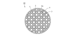
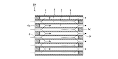
- Diesel engine exhaust gas contains PM (Particulate Matter: particulate matter) whose main component is soot made of carbon and SOF content (Soluble Organic Fraction) consisting of high-boiling hydrocarbon components. If released into the atmosphere, the human body and the environment may be adversely affected. For this reason, it has been conventionally performed to install a ceramic honeycomb filter for collecting PM in the exhaust pipe of a diesel engine. An example of a ceramic honeycomb filter for collecting PM in exhaust gas and purifying the exhaust gas is shown in FIGS.
- the ceramic honeycomb filter 10 includes a ceramic honeycomb structure including a porous partition wall 2 and an outer peripheral wall 1 forming a large number of outflow side sealing channels 3 and inflow side sealing channels 4, and an outflow side sealing channel 3
- the upstream side sealing portion 6a and the downstream side sealing portion 6c that alternately seal the exhaust gas inflow side end surface 8 and the exhaust gas outflow side end surface 9 of the inflow side sealing channel 4 in a checkered pattern.
- the outer peripheral wall 1 of the ceramic honeycomb filter is gripped so as not to move during use by a gripping member (not shown) formed of a metal mesh or ceramic mat or the like, and is placed in a metal storage container (not shown). Is arranged.
- the exhaust gas flows in from the outflow side sealing flow path 3 opened in the exhaust gas inflow side end face 8 and passes through the partition wall 2 as indicated by a dotted arrow in FIG.
- the exhaust gas passes through the partition wall 2 more specifically, when the exhaust gas passes through the communication hole formed by the pores communicating with each other on the surface and inside of the partition wall 2, PM in the exhaust gas is collected and the exhaust gas Purification is performed.
- the purified exhaust gas flows out from the inflow side sealing flow path 4 opened in the exhaust gas outflow side end face 9, and is released into the atmosphere.
- nanoparticles with a particle size of 50 mm or less in PM. These nanoparticles have a higher deposition rate on the respiratory system when inhaled into the body than when larger particles of the same mass are inhaled.
- the nanoparticle since the nanoparticle has a relatively large surface area per volume, when a toxic chemical substance is adsorbed on the particle surface, it may be a PM particle having a stronger toxicity. Since the amount of nanoparticles contained in PM is low in mass, the current PM mass standard regulation is insufficient, and as a future emission regulation, the emission of nanoparticles that greatly affects the number of emitted particles is suppressed. It is predicted that a standard (particle number standard) will be established. For this reason, in addition to excellent pressure loss characteristics, honeycomb filters are required to improve the collection rate based on the number of PM particles, especially the number of nanoparticles, rather than the collection rate based on the current PM mass.
- honeycomb filters are required to improve the collection rate based on the number of PM particles, especially the
- Special Table 2005-530616 consists of a cordierite honeycomb structure with the end closed, and the value d50 / (d50 + d90) obtained from the pore size distribution is less than 0.70, and the formula [d50 / (d50 + d90)] / [% porosity / 100] Soot adhesion factor Sf as defined by Sf is less than 1.55 and thermal expansion coefficient (25-800 ° C) is below 17 ⁇ 10 -7 / ° C Disclosed is a ceramic filter that captures and combusts exhaust particulates. By having such a pore structure (pore size distribution and pore connectivity), a low pressure is achieved even when PM is attached. It states that the loss can be maintained.
- Japanese Patent Laid-Open No. 2002-219319 is made of a material having cordierite having a controlled pore distribution as a main crystal phase, and the pore distribution is such that the pore volume having a pore diameter of less than 10 ⁇ m is 15% or less of the total pore volume.
- a porous honeycomb filter in which the pore volume with a pore diameter of 10 to 50 ⁇ m is 75% or more of the total pore volume, and the pore volume with a pore diameter of more than 50 ⁇ m is 10% or less of the total pore volume. Since this porous honeycomb filter has the pore distribution as described above, it is described that the collection efficiency of PM and the like is high, and that an increase in pressure loss due to pore clogging can be prevented. Yes. JP 2002-219319 describes that such pore distribution can be controlled by controlling the particle size of the silica component of the cordierite forming raw material and reducing the concentration of kaolin.
- Japanese Patent Laid-Open No. 2003-40687 is mainly composed of cordierite, has a porosity of 55 to 65%, an average pore diameter of 15 to 30 ⁇ m, and the total area of pores opened on the partition wall surface is 35% of the total area of the partition wall surface.
- the PM collection performance of the exhaust gas purification filters described in JP 2005-530616, JP 2002-219319 and JP 2003-40687 is enhanced by the accumulation of PM to some extent, but the use is started.
- the state before the initial PM is deposited (when the ceramic honeycomb filter is used from an unused state or when it is reused after being regenerated) is not necessarily sufficient.
- the collection efficiency of nano-sized PM which has come to be regarded as a problem with the tightening of exhaust gas regulations, is insufficient, and harmful nano-sized PM is discharged without being collected.
- JP-A-2004-360654 discloses that the porosity of the partition wall is 55 to 75%, the average pore diameter is 15 to 40 ⁇ m, the total area of the pores opened on the partition wall surface is 10 to 30% of the total area of the partition wall surface, and the partition wall surface Discloses a ceramic honeycomb filter having 300 or more pores / mm 2 having an equivalent circle diameter of 5 to 20 ⁇ m among the pores opened in the hole.
- the ceramic honeycomb filter described in Japanese Patent Application Laid-Open No. 2004-360654 has achieved some improvement in the collection rate on the basis of PM mass, it is effective to use nanoparticles in the state before PM is deposited at the beginning of use. It is difficult to collect. In other words, the collection efficiency on the basis of the number of PM particles is low, and it is unlikely that the regulation based on the number of particles will be cleared.
- JP-T-2011-516371 is a porous ceramic body made of a polycrystalline ceramic having an anisotropic microstructure, wherein the anisotropic microstructure is an oriented polycrystalline multiphase network (reticular). discloses a porous ceramic body having an anisotropy factor Af-pore-long of 1.2 ⁇ Af-pore-long ⁇ 5, and has a narrow pore size distribution and a porosity of more than 50%. And a ceramic article having any median pore size in the range of 12 to 25 ⁇ m.
- This ceramic article exhibits high strength, low coefficient of thermal expansion (CTE) and high porosity, such as automotive substrates, applications such as diesel or gasoline particulate filters, and catalytic filters incorporating the functionality of partial or complete NOx addition It describes that it can be used for functional filters.
- CTE coefficient of thermal expansion
- high porosity such as automotive substrates, applications such as diesel or gasoline particulate filters, and catalytic filters incorporating the functionality of partial or complete NOx addition It describes that it can be used for functional filters.
- the porosity of the partition wall is 40-60%
- the opening area ratio of the pores opened on the partition wall surface Is 15% or more
- the opening diameter of the pores opened on the surface of the partition wall is represented by an equivalent circle diameter (diameter of a circle having an area equivalent to the opening area of the pores).
- the median opening diameter on the basis of the area is 10 ⁇ m or more and less than 40 ⁇ m
- the circle equivalent diameter is 10 ⁇ m or more
- the pore density of less than 40 ⁇ m is 350 pores / mm 2 or more
- the circle equivalent diameter is 10 ⁇ m or more and 40 ⁇ m.
- a ceramic honeycomb structure is disclosed in which the average value of circularity of pores of less than 1 is 1 to 2.
- the ceramic honeycomb structure described in International Publication No. 2011/027837 maintains a low pressure loss and improves the PM collection rate at the beginning of collection after regeneration. It describes that nano-sized PM that has come to be seen can be efficiently collected.
- the distribution ratio (V all 90 / V all 10)) is 10 or less, and the particle size (V all 90) [ ⁇ m] at the 90 volume% and the particle size (V all 10) [ ⁇ m] at the 10 product% Of the honeycomb structure using the difference (volume particle size distribution width (V all 90-V all 10)) of 25 m or less, the obtained honeycomb structure has a high porosity, And because the pore size distribution is sharp, the collection filter for exhaust gas, especially particulate matter (particulate) in the exhaust gas of diesel engine It is described as being useful as a diesel particulate filter (DPF) for trapping.
- DPF diesel particulate filter
- the object of the present invention is to effectively collect nanoparticles that greatly affect the number of discharged particles even in the state before PM is deposited at the beginning of use, and the collection rate based on the number of PM particles It is another object of the present invention to provide a ceramic honeycomb structure and a method for manufacturing the same, in which pressure loss characteristics are hardly deteriorated even when PM is collected and accumulated.
- the ceramic honeycomb structure of the present invention has a large number of flow paths partitioned by porous partition walls,
- the partition is (a) 50-60% porosity, (b) In the pore distribution measured by the mercury intrusion method, (i) a pore diameter d5 at which the cumulative pore volume is 5% of the total pore volume is 22 ⁇ m or more and less than 55 ⁇ m, 10% pore diameter d10 is 15-35 ⁇ m, 50% pore diameter (median pore diameter) d50 of 10-20 ⁇ m, The pore diameter d85 that becomes 85% is 5-9 ⁇ m, 90% pore diameter d90 is 3-8 ⁇ m, 98% pore diameter d98 is 2.5 ⁇ m or less, (d10-d90) / d50 is 1.3-1.8, (d50-d90) / d50 is 0.45 to 0.75, and (d10-d50) / d50 is 0.75 to 1.1, (ii) The difference between the logarithm of the pore diameter
- the pore diameter d2 at which the cumulative pore volume is 2% of the total pore volume is preferably 75 to 250 ⁇ m, and the pore volume of 20 ⁇ m or more is preferably 0.12 cm 3 / g or less.
- the porosity is preferably 52 to 60%.
- the median pore diameter d50 is preferably 10 to 18 ⁇ m.
- the ⁇ is preferably 0.3 or less.
- the method of the present invention for producing the ceramic honeycomb structure is as follows. Extruding a clay containing a pore former made of ceramic raw material and hollow resin particles into a predetermined molded body, and drying and firing the molded body, The clay contains 3 to 9% by mass of the pore former with respect to 100% by mass of the ceramic raw material, The pore former has a median diameter D50 of 20 to 53 ⁇ m, a curve showing the relationship between the particle diameter and the cumulative volume, and a particle diameter D5 at a cumulative volume corresponding to 5% of the total volume is 12 to 27 ⁇ m.
- Particle diameter D10 at a cumulative volume equivalent to 10% is 15-30 ⁇ m
- particle diameter D90 at a cumulative volume equivalent to 90% of the total volume is 50-75 ⁇ m
- particles at a cumulative volume equivalent to 95% of the total volume The diameter D95 is 60 to 90 ⁇ m
- D50 / (D90-D10) is 0.85 to 1.30.
- the ceramic raw material contains 15 to 25% by mass of silica, 40 to 43% by mass of talc and 15 to 30% by mass of alumina with respect to 100% by mass of the ceramic raw material;
- the particle size in the corresponding cumulative volume, D20 ⁇ D80. ] Is 0.4 or less,
- the talc has a median diameter D50 of 5 to 15 ⁇ m, D10 of 10 ⁇ m or less, and D90 of 25 ⁇ m or more,
- the alumina is characterized in that the median diameter D50 is 3 to 6 ⁇ m, D90 is 20 ⁇ m or less, and the proportion of particles having a particle diameter of 25 ⁇ m or more is 0.4 mass% or less.
- the clay contains 3.5 to 8% by mass of the pore former with respect to 100% by mass of the ceramic raw material.
- the filter comprising the ceramic honeycomb structure of the present invention is in a state before PM is deposited at the beginning of use (when the ceramic honeycomb filter is used from an unused state or when it is used again after being regenerated).
- nano-sized PM that greatly affects the number of particles in the exhaust gas can be effectively collected. Therefore, the collection rate on the basis of the number of PM particles is improved, and the pressure loss characteristic when PM is collected and accumulated does not deteriorate, so it is possible to cope with further strengthening of exhaust gas regulations.
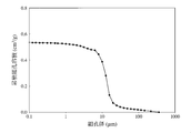
- 3 is a graph showing the relationship between the pore diameter of the partition walls and the cumulative pore volume of the ceramic honeycomb structure of Example 1 measured by a mercury intrusion method. It is a graph for demonstrating the method of calculating
- Ceramic honeycomb structure has a large number of flow paths partitioned by porous partition walls, and the partition walls include: (a) Porosity of 50-60%, (b) Pore distribution measured by mercury porosimetry, (i) Pore diameter d5 at which the cumulative pore volume is 5% of the total pore volume is 22 ⁇ m or more and less than 55 ⁇ m, 10% of the pore diameter d10 is 15 to 35 ⁇ m, 50% of the pore diameter (median pore diameter) d50 10 to 20 ⁇ m, 85% pore diameter d85 is 5 to 9 ⁇ m, 90% pore diameter d90 is 3 to 8 ⁇ m, 98% pore diameter d98 is 2.5 ⁇ m or less, and (d10-d90) / d50 is 1.3.
- Porosity of partition wall The porosity of the partition wall is 50 to 60%. When the porosity is less than 50%, it is difficult to maintain a low pressure loss when PM is collected and accumulated, while when the porosity exceeds 60%, the nano-sized PM collection rate decreases. .
- the porosity is preferably 52 to 60%, more preferably 54 to 59%.
- the porosity of the partition walls is measured by a mercury intrusion method described later.
- the pore diameter d2 at which the cumulative pore volume is 2% of the total pore volume is preferably 75 to 250 ⁇ m.
- the pore distribution curve of the partition walls measured by the mercury intrusion method is a curve (cumulative pore volume curve) in which the cumulative pore volume is plotted against the pore diameter, for example, as shown in FIG. The values are integrated from the larger pore diameter side toward the smaller side. Note that d2>d5>d10>d50>d85>d90> d98.
- the pore diameter d2 at which the cumulative pore volume is 2% of the total pore volume is preferably 75 to 250 ⁇ m.
- d2 is preferably 80 to 240 ⁇ m, more preferably 90 to 230 ⁇ m.
- the pore diameter d5 at which the cumulative pore volume is 5% of the total pore volume is 22 ⁇ m or more and less than 55 ⁇ m.
- d5 is preferably 28 to 54 ⁇ m, more preferably 33 to 53 ⁇ m.
- the pore diameter d10 at which the cumulative pore volume is 10% of the total pore volume is 15 to 35 ⁇ m.
- d10 is preferably 21 to 45 ⁇ m, more preferably 22 to 40 ⁇ m.
- the median pore diameter d50 is 10 to 20 ⁇ m. When the median pore diameter d50 is less than 10 ⁇ m, it is difficult to keep the initial pressure loss at the start of use low. On the other hand, when the median pore diameter d50 is more than 20 ⁇ m, the number of pores having a pore diameter of 10 to 20 ⁇ m effective for PM collection decreases, and the nano-size PM collection rate decreases.
- the median pore diameter d50 is preferably 12 to 18 ⁇ m, and more preferably 13 to 16 ⁇ m.
- the pore diameter d85 at which the cumulative pore volume is 85% of the total pore volume is 5 to 9 ⁇ m.
- d85 is preferably 5.5 ⁇ m or more, and more preferably 6 ⁇ m or more.
- d85 is preferably 8.5 ⁇ m or less.
- the pore diameter d90 at which the cumulative pore volume is 90% of the total pore volume is 3 to 8 ⁇ m.
- d90 is preferably 3.5 ⁇ m or more, more preferably 4.5 ⁇ m or more.
- d90 is preferably 7.5 ⁇ m or less, more preferably 7 ⁇ m or less.
- the pore diameter d98 at which the cumulative pore volume is 98% of the total pore volume is 2.5 ⁇ m or less.
- d98 is preferably 2 ⁇ m or less, more preferably 1.5 ⁇ m or less.
- (D10-d90) / d50 is 1.3-1.8.
- (d10-d90) / d50 is less than 1.3, it is difficult to maintain a low pressure loss when PM is collected and accumulated, and when it exceeds 2, it is difficult to maintain a low initial pressure loss at the start of use.
- (d10-d90) / d50 is preferably 1.35 to 1.7, more preferably 1.4 to 1.6.
- (D50-d90) / d50 is 0.45-0.75.
- (d50-d90) / d50 is less than 0.45, it is difficult to maintain a low pressure loss when PM is collected and accumulated, and when it is more than 0.75, the nano-sized PM collection rate decreases.
- (d50-d90) / d50 is preferably 0.5 to 0.7, more preferably 0.55 to 0.65, and even more preferably 0.55 to 0.60.
- (D10-d50) / d50 is between 0.75 and 1.1.
- (d10-d50) / d50 is less than 0.75, it is difficult to maintain a low pressure loss when PM is collected and accumulated, and when it exceeds 1.1, the nano-size PM collection rate is lowered.
- (d10-d50) / d50 is preferably 0.8 to 1.05, more preferably 0.85 to 1.0.
- the pore volume exceeding 100 ⁇ m is preferably 0.03 cm 3 / g or less.
- the pore volume of more than 100 ⁇ m is more than 0.03 cm 3 / g, the nano-sized PM trapping rate decreases.
- the pore volume of more than 100 ⁇ m is preferably 0.025 cm 3 / g or less, more preferably 0.02 cm 3 / g or less.
- the pore volume exceeding 100 ⁇ m is 0.03 cm 3 /
- the condition of g or less is inevitably satisfied.
- the pore volume of 20 ⁇ m or more is preferably 0.12 cm 3 / g or less.
- the pore volume of 20 ⁇ m or more is preferably 0.10 cm 3 / g or less, more preferably 0.08 cm 3 / g or less.
- the cumulative pore volume by the mercury intrusion method can be measured using an Autopore III 9410 manufactured by Micromeritics.
- a test piece (10 mm x 10 mm x 10 mm) cut out from the ceramic honeycomb structure was placed in the measurement cell, and after the pressure inside the cell was reduced, mercury was introduced and pressurized. This is done by determining the volume of mercury pushed into the pores present in the piece. At this time, the larger the applied pressure, the more the mercury penetrates into finer pores.Therefore, from the relationship between the applied pressure and the volume of mercury pushed into the pores, the pore diameter and the cumulative pore volume (maximum Of the pore volume from the pore diameter to a specific pore diameter).
- the total pore volume, porosity, pore diameter d2 ( ⁇ m) that the cumulative pore volume is 2% of the total pore volume, 5% pore diameter d5 ( ⁇ m) 10% pore diameter d10 ( ⁇ m), 20% pore diameter d20 ( ⁇ m), 50% pore diameter (median pore diameter) d50 ( ⁇ m), 80% pore diameter d80 ( ⁇ m), 85% pore diameter d85 ( ⁇ m), 90% pore diameter d90 ( ⁇ m), 98% pore diameter d98 ( ⁇ m), pore volume greater than 100 ⁇ m, (d10-d90) / d50, (d50 -d90) / d50 and (d10-d50) / d50, and the difference between the logarithm of the pore diameter d20 at which the cumulative pore volume is 20% of the total pore volume and the logarithm of the pore diameter d80 at 80% ⁇ log (d20)
- the porosity can be determined by calculation from the total pore volume and the true specific gravity of the partition wall material. For example, if the material of the partition walls of the ceramic honeycomb structure is cordierite, the true specific gravity of cordierite is 2.52 g / cm 3 and the total pore volume is V, [2.52V / (1+ 2.52V)] ⁇ 100 (%).
- the ceramic honeycomb structure preferably has a thermal expansion coefficient of 13 ⁇ 10 ⁇ 7 / ° C. or less in the flow channel direction (A axis) between 20 and 800 ° C. Since the ceramic honeycomb structure having such a thermal expansion coefficient has high thermal shock resistance, it can sufficiently be practically used as a ceramic honeycomb filter for removing fine particles contained in exhaust gas of a diesel engine. .
- the thermal expansion coefficient is preferably 3 ⁇ 10 ⁇ 7 to 11 ⁇ 10 ⁇ 7 .
- the ceramic honeycomb structure preferably has an average partition wall thickness of 9 to 15 mil (0.229 to 0.381 mm) and an average cell density of 150 to 300 cpsi (23.3 to 46.5 cells / cm 2 ).
- the pressure loss can be kept low at the start of use, the PM collection rate based on the number of particles can be improved, and the pressure loss characteristic when PM is collected and accumulated Is improved.
- the average partition wall thickness is less than 9 mil, the strength of the partition wall decreases, whereas when it exceeds 15 mil, it is difficult to maintain a low pressure loss.
- the cross-sectional shape of the cell in the flow channel direction may be any of a quadrilateral, a polygon such as a hexagon, a circle, an ellipse, or the like, or may be an asymmetric shape having different sizes between the inflow side end surface and the outflow side end surface.
- the ceramic honeycomb structure is a filter for purifying exhaust gas exhausted from a diesel engine, so heat-resistant ceramics, that is, alumina, mullite, cordier, etc. Ceramics mainly composed of erlite, silicon carbide, silicon nitride, zirconia, aluminum titanate, lithium aluminum silicate and the like are preferable. Of these, cordierite with excellent thermal shock resistance and cordierite or aluminum titanate as the main crystal are preferred.
- the main crystal phase is cordierite, it may contain other crystal phases such as spinel, mullite, sapphirine, and may further contain a glass component.
- the main crystal phase is aluminum titanate, elements such as Mg and Si may be dissolved in the aluminum titanate crystal phase, and other crystal phases such as mullite may be contained. A glass component may be contained as a boundary phase.
- Ceramic honeycomb filter The ceramic honeycomb filter is formed by alternately plugging the exhaust gas inflow side or the exhaust gas outflow side of the flow path of the ceramic honeycomb structure of the present invention.
- a low pressure loss can be maintained and the PM collection rate based on the number of particles can be improved, and PM is collected and accumulated.
- a ceramic honeycomb filter with improved pressure loss characteristics can be obtained.
- the plugging formed in the flow path does not necessarily have to be formed on the end surface portion on the exhaust gas inflow side or exhaust gas outflow side of the flow path, and enters the flow path from the inflow side end face or the outflow side end face. It may be formed at a different position.
- a method for manufacturing a ceramic honeycomb structure of the present invention includes extruding a clay containing a pore former made of a ceramic raw material and hollow resin particles into a predetermined molded body, A step of drying and firing the molded body,
- the clay contains 3 to 9% by mass of the pore former with respect to 100% by mass of the ceramic raw material
- the pore former has a median diameter D50 of 20 to 53 ⁇ m, a curve showing the relationship between the particle diameter and the cumulative volume, and a particle diameter D5 at a cumulative volume corresponding to 5% of the total volume is 12 to 27 ⁇ m.
- Particle diameter D10 at a cumulative volume equivalent to 10% is 15-30 ⁇ m
- particle diameter D90 at a cumulative volume equivalent to 90% of the total volume is 50-75 ⁇ m
- particles at a cumulative volume equivalent to 95% of the total volume The diameter D95 is 60 to 90 ⁇ m
- D50 / (D90-D10) is 0.85 to 1.30.
- the ceramic raw material contains 15 to 25% by mass of silica, 40 to 43% by mass of talc and 15 to 30% by mass of alumina with respect to 100% by mass of the ceramic raw material;
- the particle size in the corresponding cumulative volume, D20 ⁇ D80. ] Is 0.4 or less,
- the talc has a median diameter D50 of 5 to 15 ⁇ m, D10 of 10 ⁇ m or less, and D90 of 25 ⁇ m or more,
- the alumina has a median diameter D50 of 3 to 6 ⁇ m, D90 of 20 ⁇ m or less, and the proportion of particles having a particle diameter of 25 ⁇ m or more is 0.4 mass% or less.
- the porosity is 50-60%
- the pore distribution measured by the mercury intrusion method (i) the cumulative pore volume is 2% of the total pore volume.
- Pore diameter d2 is 75 to 250 ⁇ m
- 5% pore diameter d5 is 22 ⁇ m or more and less than 55 ⁇ m
- 10% pore diameter d10 is 15 to 35 ⁇ m
- 50% pore diameter (median pore diameter) d50 is 10 to 20 ⁇ m
- 85 % Pore diameter d85 is 5-9 ⁇ m
- 90% pore diameter d90 is 3-8 ⁇ m
- 98% pore diameter d98 is 2.5 ⁇ m or less
- (d10-d90) / d50 is 1.3-1.8
- (d50- d90) / d50 is 0.45 to 0.75
- (d10-d50) / d50 is 0.75 to 1.1
- the pores formed in the ceramic are composed of pores generated by melting the ceramic raw material in the firing process and pores generated by burning out the pore former. Therefore, the pores produced when the ceramic is fired can be controlled by setting the median diameter and particle size distribution of the ceramic raw material and the pore former to the ranges described above.
- the resin particles burn and become voids when the molded body containing the ceramic raw material and the pore former is fired.
- the raw material is fired to form pores.
- hollow resin particles that generate less heat by combustion than solid resin particles firing cracks in the process of firing the molded body are less likely to occur.
- the pore diameter of the partition walls can be in the above range.
- the nano-size PM trapping rate is improved by forming the pores formed by firing the ceramic raw material and the pores formed from the pore former in a predetermined pore diameter range with good communication.
- the ceramic honeycomb structure of the present invention having improved pressure loss characteristics when PM is collected and accumulated can be obtained.
- Pore-forming material used in the present invention comprises hollow resin particles, and the amount added is 3 to 9% by mass with respect to 100% by mass of the ceramic raw material.
- the added amount of the pore former is out of this range, it is difficult to obtain a partition having the pore structure.
- the added amount of the pore former is less than 3% by mass, it becomes difficult to obtain a partition wall with a porosity of 50% or more, and the pressure loss characteristic when PM is collected and accumulated is deteriorated.
- the added amount of the pore former exceeds 9% by mass, the porosity of the partition walls may exceed 60%, and the nano-size PM collection rate decreases.
- the added amount of the pore former is preferably 3.5 to 8% by mass, and more preferably 4 to 7% by mass.
- the median diameter D50 of the pore former particles is 20 to 53 ⁇ m. When the median diameter D50 is less than 20 ⁇ m, a low pressure loss when PM is collected and accumulated cannot be maintained. When the median diameter D50 exceeds 53 ⁇ m, the formed pores become coarse, so that the nano-size PM trapping rate decreases.
- the median diameter D50 of the pore former particles is preferably 25 to 50 ⁇ m, more preferably 30 to 50 ⁇ m.
- the pore former particles in a curve showing the relationship between the particle diameter and the cumulative volume (a value obtained by accumulating the particle volume below a specific particle diameter), the particle diameter D5 in the cumulative volume corresponding to 5% of the total volume Is 12-27 ⁇ m, particle size D10 in the cumulative volume equivalent to 10% of the total volume is 15-30 ⁇ m, particle size D90 in the cumulative volume equivalent to 90% of the total volume is 50-75 ⁇ m, 95% of the total volume
- the particle diameter D95 in the cumulative volume corresponding to is 60 to 90 ⁇ m, and D50 / (D90-D10) is 0.9 to 1.3.
- the pore former particles have such a particle size distribution, and by adjusting the particle size and particle size distribution of the ceramic raw material, which will be described later, the partition wall having the pore structure can be easily obtained.
- the particle diameter D5 in the cumulative volume corresponding to 5% of the total volume is preferably 14 to 25 ⁇ m, more preferably 16 to 23 ⁇ m.
- the particle diameter D10 in the cumulative volume corresponding to 10% of the total volume is preferably 17 to 28 ⁇ m, more preferably 19 to 26 ⁇ m.
- the particle diameter D90 in the cumulative volume corresponding to 90% of the total volume is preferably 55 to 72 ⁇ m, more preferably 56 to 70 ⁇ m, and most preferably 56 ⁇ m or more and less than 66 ⁇ m.
- the particle diameter D95 in the cumulative volume corresponding to 95% of the total volume is preferably 65 to 88 ⁇ m, more preferably 67 to 85 ⁇ m, and most preferably 67 to 80 ⁇ m.
- D50 / (D90-D10) is preferably 0.90 to 1.20, more preferably 1.0 to 1.15.
- the particle diameter of the pore former can be measured using a Microtrac particle size distribution measuring device (MT3000) manufactured by Nikkiso Co., Ltd.
- the sphericity of the pore former particles is preferably 0.5 or more. When the sphericity of the pore former particles is less than 0.5, it is not preferable because the number of pores having an acute angle portion that tends to be a starting point of destruction increases and the strength of the honeycomb structure may be lowered.
- the sphericity of the pore former particles is preferably 0.7 or more, and more preferably 0.8 or more. Note that the sphericity of the pore former particles was obtained by dividing the projected area of the pore former particles by the area of a circle whose diameter is the maximum value of a straight line passing through the center of gravity of the pore former particles and connecting two points on the outer periphery of the particle. Value, which can be obtained from an electron micrograph with an image analyzer.
- the hollow resin particles are preferably foamed resin particles.
- the resin used as the pore former particles (poly) methyl methacrylate, polybutyl methacrylate, polyacrylic ester, polystyrene, polyacrylic ester, polyethylene, polyethylene terephthalate, methyl methacrylate / acrylonitrile copolymer and the like are suitable.
- the hollow resin particles preferably have an outer shell thickness of 0.1 to 3 ⁇ m, and preferably contain a gas such as hydrocarbon, and the resin particles contain 70 to 95% moisture on the surface. Those are preferred.
- the true specific gravity is preferably 0.01 to 0.05.
- the ceramic raw material contains 15 to 25% by mass of silica, 40 to 43% by mass of talc and 15 to 30% by mass of alumina with respect to 100% by mass of the ceramic raw material.
- the ceramic raw material is preferably a cordierite forming raw material.
- the main crystal is cordierite (the main component has a chemical composition of 42 to 56% by mass of SiO 2 , 30 to 45% by mass of Al 2 O 3 and 12 to 16% by mass of MgO).
- each raw material powder which has a silica source component, an alumina source component, and a magnesia source component is mix
- the pores formed in the ceramic having cordierite as the main crystal are due to pores generated by firing the ceramic raw material silica and talc and pores generated by burning the pore former. Therefore, by adjusting the particle size and particle size distribution of the ceramic raw materials such as silica and talc together with the pore former described above, the pores generated when the cordierite ceramic is fired can be controlled. Among these, silica and pore former occupy most of the formed pores, and thus contribute greatly to the pore structure.
- Silica Silica is known to exist stably up to a higher temperature than other raw materials, and melt and diffuse at 1300 ° C. or higher to form pores. Therefore, when 15 to 25% by mass of silica is contained, a desired amount of pores can be obtained.
- silica is contained in an amount exceeding 25% by mass, kaolin and / or talc, which are other silica source components, must be reduced in order to maintain the main crystal as cordierite. The effect of lowering thermal expansion (effect obtained by orienting kaolin during extrusion molding) is reduced, and the thermal shock resistance is lowered.
- the amount is less than 15% by mass, the number of pores opened on the partition wall surface is reduced, so that a low pressure loss may not be obtained when PM is collected and accumulated.
- the content of silica is preferably 17 to 23% by mass.
- Silica has a median diameter D50 of 15-30 ⁇ m and a curve showing the relationship between particle diameter and cumulative volume.
- the particle diameter D10 at a cumulative volume corresponding to 10% of the total volume is 10-20 ⁇ m, and 90% of the total volume.
- the ratio of particles having a particle diameter D90 of 40-60 ⁇ m and a particle diameter of 5 ⁇ m or less in a cumulative volume corresponding to is 1 mass% or less, the ratio of particles having a particle diameter of 10 ⁇ m or less is 3 mass% or less, 100 ⁇ m or more
- the median diameter D50 of silica is preferably 17 to 28 ⁇ m, more preferably 19 to 26 ⁇ m.
- the D10 of silica is preferably 12 to 18 ⁇ m, more preferably 13 to 17 ⁇ m.
- the D90 of silica is preferably 45 to 55 ⁇ m, more preferably 47 to 53 ⁇ m.
- the ratio of silica particles having a particle diameter of 5 ⁇ m or less is preferably 0.7% by mass or less, more preferably 0.2% by mass or less, and the ratio of silica particles having a particle diameter of 10 ⁇ m or less is preferably 2% by mass or less.
- the ratio of silica particles having a particle diameter of 100 ⁇ m or more is preferably 2% by mass or less, and the ratio of silica particles having a particle diameter of 200 ⁇ m or more is preferably 0.7% by mass or less, more preferably 0.2% by mass or less.
- the particle size distribution deviation SD of silica is preferably 0.36 or less, more preferably 0.33 or less.
- the sphericity of the silica particles is preferably 0.5 or more. If the sphericity of the silica particles is less than 0.5, it is not preferable because the number of pores having sharp corners that tend to be the starting point of destruction increases and the strength of the honeycomb structure may be lowered.
- the sphericity of the silica particles is preferably 0.6 or more, and more preferably 0.7 or more.
- the sphericity of the silica particle is a value obtained by dividing the projected area of the silica particle by the area of a circle whose diameter is the maximum value of the straight line connecting the two points on the outer periphery of the particle through the center of gravity of the silica particle. It can be obtained by an image analysis apparatus.
- the silica particles may be crystalline or amorphous, but are preferably amorphous from the viewpoint of adjusting the particle size distribution.
- Amorphous silica can be obtained by crushing an ingot produced by melting high-purity natural silica at high temperature.
- Silica particles may contain Na 2 O, K 2 O, and CaO as impurities, but in order to prevent an increase in the thermal expansion coefficient, the content of the impurities is preferably 0.1% or less in total. .
- Silica particles with high sphericity can be obtained by pulverizing high-purity natural silica and spraying it in a high-temperature flame.
- the silica particles can be melted and spheroidized simultaneously by thermal spraying into a high-temperature flame to obtain amorphous silica having a high sphericity.
- Kaolin powder can be blended in addition to the silica powder.
- the kaolin powder is preferably contained in an amount of 1 to 15% by mass. If the kaolin powder exceeds 15% by mass, it may be difficult to adjust d98 to 5 ⁇ m or less in the pore distribution of the ceramic honeycomb structure, and if it is less than 1% by mass, the ceramic honeycomb structure The thermal expansion coefficient of increases.
- the kaolin powder content is more preferably 4 to 8% by mass.
- the orientation of kaolin particles is greatly influenced by their shape.
- the cleavage index of kaolin particles which is an index that quantitatively indicates the shape of kaolin particles, is preferably 0.80 or more, and more preferably 0.85 or more.
- the ceramic raw material contains 40 to 43% by mass of talc with respect to 100% by mass of the ceramic raw material.
- the talc is a cumulative volume corresponding to 10% of the total volume in a curve showing a relationship between a median diameter D50 of 5 to 15 ⁇ m, a particle diameter and an accumulated volume (a value obtained by accumulating a particle volume below a specific particle diameter).
- the particle diameter D10 is 10 ⁇ m or less, and similarly, the particle diameter D90 at a cumulative volume corresponding to 90% of the total volume is 25 ⁇ m or more.
- Talc is a compound mainly composed of MgO and SiO 2 , reacts with the Al 2 O 3 component present in the surroundings in the firing process, and melts to form pores.
- talc having a small particle size together with the Al 2 O 3 source material, a large number of small-diameter pores can be dispersed in the partition walls, and the connectivity of the pores in the partition walls can be improved.
- the median diameter D50 of talc is less than 5 ⁇ m, the pore connectivity is lowered, and the pressure loss characteristic when PM is collected and accumulated is lowered.
- the median diameter D50 of talc exceeds 15 ⁇ m, coarse pores increase and the nano-size PM trapping rate is lowered.
- the median diameter D50 of talc is preferably 6 to 14 ⁇ m, and more preferably 8 to 12 ⁇ m.
- D10 of talc is preferably 8 ⁇ m or less, more preferably 7 ⁇ m or less.
- the D90 of talc is preferably 25 to 45 ⁇ m, more preferably 25 to 40 ⁇ m or less.
- Talc is preferably plate-like particles from the viewpoint of reducing the thermal expansion coefficient of the ceramic honeycomb structure whose main component of the crystal phase is cordierite.
- the form factor indicating the tabularity of the talc particles is preferably 0.5 or more, more preferably 0.6 or more, and most preferably 0.7 or more.
- Talc may contain Fe 2 O 3 , CaO, Na 2 O, K 2 O and the like as impurities.
- the content of Fe 2 O 3 is preferably 0.5 to 2.5% by mass in the magnesia source material, and the content of Na 2 O, K 2 O and CaO is thermal expansion. From the viewpoint of reducing the coefficient, the total content is preferably 0.5% by mass or less.
- the ceramic raw material contains 15 to 30% by mass of alumina with respect to 100% by mass of the ceramic raw material.
- the alumina has a median diameter D50 of 3 to 6 ⁇ m, and in a curve showing the relationship between the particle diameter and the cumulative volume, the particle diameter D90 at a cumulative volume corresponding to 90% of the total volume is 20 ⁇ m or less, and 25 ⁇ m or more.
- the median diameter D50 of alumina is preferably 3.5 to 6 ⁇ m, more preferably 4 to 5.5 ⁇ m, D90 is preferably 1 to 20 ⁇ m, more preferably 5 to 20 ⁇ m, and a particle size of 25 ⁇ m or more.
- the ratio of the particles having is preferably 0.2% by mass or less.
- As the alumina raw material it is preferable to use aluminum hydroxide in addition to alumina.
- the total content of Na 2 O, K 2 O and CaO as impurities in alumina and aluminum hydroxide is preferably 0.5% by mass or less, more preferably 0.3% by mass or less, and most preferably 0.1% by mass or less. .
- the ceramic honeycomb structure is kneaded by adding water, adding a binder, and if necessary, additives such as a dispersant and a surfactant to the ceramic raw material and pore former, followed by dry mixing. Then, the obtained plastic clay is extruded from a known mold for forming a honeycomb structure by a known extrusion method, for example, an extrusion method such as a plunger type or a screw type, to form a honeycomb structure formed body. After forming and drying this molded body, it is manufactured by subjecting the end face and outer periphery to processing as necessary and firing.
- a known extrusion method for example, an extrusion method such as a plunger type or a screw type
- Calcination is performed using a continuous furnace or a batch furnace while adjusting the heating and cooling rates.
- the ceramic raw material is a cordierite forming raw material, it is kept at 1350-1450 ° C. for 1-50 hours, and after the cordierite main crystals are sufficiently formed, it is cooled to room temperature.
- the temperature increase rate is a temperature range in which the binder decomposes so that cracks do not occur in the formed body in the firing process, particularly when manufacturing a large ceramic honeycomb structure having an outer diameter of 150 mm or more and a total length of 150 mm or more (for example, The temperature is preferably 0.2 to 10 ° C./hr at 150 to 350 ° C.
- Cooling is preferably performed at a rate of 20 to 40 ° C./h, particularly in the range of 1400 to 1300 ° C.
- the obtained honeycomb structure can be made into a ceramic honeycomb filter by plugging the end of a desired flow path by a known method. Note that this plugged portion may be formed before firing.
- Examples 1 to 3 and Comparative Example 1 Silica powder, talc powder and alumina powder, aluminum hydroxide powder and kaolin powder having the particle shapes (particle size, particle size distribution, etc.) shown in Tables 1 to 5 are adjusted so that the total amount of ceramic raw materials is 100 parts by mass. The addition amount shown in Table 7 was added to obtain a cordierite-forming raw material powder having a chemical composition of cordierite after firing.
- the pore shape material with the particle shape and true specific gravity shown in Table 6 is added in the amount shown in Table 7, and after adding and mixing methylcellulose, kneading with water and plasticizing A ceramic clay was prepared.
- the sphericity of the pore-forming particles is a circle whose diameter is the maximum value of the straight line connecting the two points on the outer circumference of the projected area A1 and the center of gravity obtained from the image of the particle taken with an electron microscope. From the area A2, the value calculated by the formula: A1 / A2 was shown as an average value for 20 particles.
- the particle size and particle size distribution of silica powder, talc powder, alumina powder, aluminum hydroxide powder, kaolin powder, and pore former were measured using a Nikkiso Co., Ltd. Microtrac particle size distribution measuring device (MT3000).
- the median diameter D50, the ratio of particle diameter of 10 ⁇ m or less, the ratio of 25 ⁇ m or more, the ratio of 100 ⁇ m or more, D90, D80, D20, D10, etc. were determined, and the particle size distribution deviation SD was determined from D80 and D20.
- the resulting clay is extruded to produce a honeycomb-shaped formed body, and after drying, the peripheral portion is removed and processed in a firing furnace for 210 hours (room temperature to 150 ° C is 10 ° C / h, 150 to 350 ° C) Is 2 ° C / hr, 350-1150 ° C is 20 ° C / h and 1150-1410 ° C is averaged at 15 ° C / hr, the maximum temperature is 1410 ° C and held for 25 hr, and 1400-1300 ° C is 30 ° C / hr hr, and 1300 to 100 ° C. were cooled at an average rate of 80 ° C./hr).
- the outer periphery of the fired ceramic honeycomb body is coated with an outer shell material made of amorphous silica and colloidal silica and dried.
- the outer diameter is 266.7 mm, the total length is 304.8 mm, the partition wall thickness is 12 mil (0.30 mm), and the cell density is 260.
- Ceramic honeycomb structures of Examples 1 to 3 and Comparative Example 1 having cpsi (40.3 cells / cm 2 ) were obtained.
- the plugging material slurry made of the cordierite forming raw material is filled in the end portions of the flow paths of these ceramic honeycomb structures so as to be alternately plugged, the plugging material slurry is dried and fired.
- the cordierite ceramic honeycomb filters of Examples and Comparative Examples were manufactured. The length of the plugged material after firing was in the range of 7 to 10 mm. Each ceramic honeycomb filter was made of two identical ones.
- the pore distribution was measured by the mercury intrusion method and the thermal expansion coefficient was measured by the following method.
- the mercury intrusion method the test piece (10 mm x 10 mm x 10 mm) cut out from the ceramic honeycomb filter is placed in a Micromeritics Autopore III measurement cell, the inside of the cell is decompressed, and then mercury is introduced. And pressurizing and determining the relationship between the pressure at the time of pressurization and the volume of mercury pushed into the pores present in the test piece.
- the pressure is converted into pore diameter, and the cumulative pore volume (equivalent to the volume of mercury) integrated from the larger pore diameter side to the smaller side is plotted against the pore diameter, and as shown in FIG. A graph showing the relationship between the pore size and the cumulative pore volume was obtained.
- the cumulative pore volume at a mercury pressure of 1800 psi (1.26 kg / mm 2 , corresponding to a pore diameter of about 0.1 ⁇ m) was defined as the total pore volume.
- the total pore volume, porosity, cumulative pore volume is 2% of the total pore volume, the pore diameter d2 is 5%, and the pore diameter d5 is 10%.
- the difference ⁇ log (d20) ⁇ log (d80) between the logarithm of the pore diameter d20 that is 20% of the logarithm and the logarithm of the pore diameter d80 that is 80% was calculated.
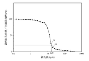
- the values of the pore diameters d2, d5, d10, d50, d85, d90 and d98 are interpolated from the measurement points obtained by the mercury intrusion method at the two nearest measurement points before and after each pore diameter. Asked. For example, in the case of d20, as shown in FIG. 4, of the measurement points obtained by the mercury intrusion method, two measurements before and after the closest to the value at which the cumulative pore volume is 20% of the total pore volume Points A and B were connected by a straight line, and the pore diameter at the point where the cumulative pore volume was 20% of the total pore volume on the straight line was defined as d20. The porosity was calculated from the measured value of the total pore volume by setting the true specific gravity of cordierite to 2.52 g / cm 3 . These results are shown in Table 8.
- the initial pressure loss is expressed by the pressure difference (pressure loss) between the inflow side and the outflow side when air is sent to the ceramic honeycomb filter fixed to the pressure loss test stand at a flow rate of 10 Nm 3 / min. .
- Pressure loss is When exceeding 1.0 kPa ( ⁇ ), (0.8) when 0.8 kPa and 1.0 kPa (0.6) when 0.6 kPa and 0.8 kPa When the pressure is 0.6 kPa or less ( ⁇ ) As an initial pressure loss was evaluated.
- Pressure loss is When exceeding 1.5 kPa ( ⁇ ), ( ⁇ ) when 1.3 kPa and 1.5 kPa or less ( ⁇ ) when 1.0 kPa and 1.3 kPa or less When the pressure is 1.0 kPa or less ( ⁇ ) The soot collection pressure loss was evaluated.
- (c) PM collection rate on the basis of the number of particles at the beginning of collection The PM collection rate on the basis of the number of particles at the beginning of collection is determined by applying an air flow rate of 10 Nm 3 to a ceramic honeycomb filter fixed to the pressure loss test stand.
- model 3936 was measured using the number of particles combustion soot flowing into the honeycomb filter 1 minute from the start of feeding 40 min after until after 41 minutes N in, and honeycomb From the number N out of the combustion soot particles flowing out from the filter, it was determined by the formula: (N in ⁇ N out ) / N in . PM collection rate 98% or more ( ⁇ ), ( ⁇ ) when 96% or more and less than 98% 95% or more and less than 96% ( ⁇ ), and Less than 95% ( ⁇ ) PM collection rate was evaluated.
- Table 9 shows that the ceramic honeycomb filters of Examples 1 to 3 of the present invention have an improved PM collection rate based on the number of particles at the beginning of collection while maintaining a low pressure loss.
- the ceramic honeycomb filter of Comparative Example 1 uses alumina with a large median diameter and a large proportion of the particle diameter of 25 ⁇ m or more, the pore diameter d5 at which the cumulative pore volume is 5% of the total pore volume is large, and PM trapping is performed. The rate was bad.
Landscapes
- Chemical & Material Sciences (AREA)
- Engineering & Computer Science (AREA)
- Ceramic Engineering (AREA)
- Chemical Kinetics & Catalysis (AREA)
- Materials Engineering (AREA)
- Structural Engineering (AREA)
- Organic Chemistry (AREA)
- Physics & Mathematics (AREA)
- Geometry (AREA)
- Manufacturing & Machinery (AREA)
- Mechanical Engineering (AREA)
- General Engineering & Computer Science (AREA)
- Combustion & Propulsion (AREA)
- Geology (AREA)
- Life Sciences & Earth Sciences (AREA)
- Filtering Materials (AREA)
- Nanotechnology (AREA)
- Processes For Solid Components From Exhaust (AREA)
- Filtering Of Dispersed Particles In Gases (AREA)
- Porous Artificial Stone Or Porous Ceramic Products (AREA)
- Catalysts (AREA)
Abstract
Description
前記隔壁は、
(a)気孔率が50~60%、
(b)水銀圧入法により測定された細孔分布において、
(i)累積細孔容積が全細孔容積の5%となる細孔径d5が22μm以上55μm未満、
10%となる細孔径d10が15~35μm、
50%となる細孔径(メジアン細孔径)d50が10~20μm、
85%となる細孔径d85が5~9μm、
90%となる細孔径d90が3~8μm、
98%となる細孔径d98が2.5μm以下、
(d10-d90)/d50が1.3~1.8、
(d50-d90)/d50が0.45~0.75、及び
(d10-d50)/d50が0.75~1.1であり、
(ii)累積細孔容積が全細孔容積の20%となる細孔径d20の対数と80%となる細孔径d80の対数との差σ=log(d20)-log(d80)が0.39以下であることを特徴とする。
セラミック原料及び中空の樹脂粒子からなる造孔材を含む坏土を所定の成形体に押出成形し、前記成形体を乾燥及び焼成する工程を有し、
前記坏土が、前記セラミック原料100質量%に対して3~9質量%の前記造孔材を含有し、
前記造孔材は、メジアン径D50が20~53μm、粒子径と累積体積との関係を示す曲線において、全体積の5%に相当する累積体積での粒子径D5が12~27μm、全体積の10%に相当する累積体積での粒子径D10が15~30μm、全体積の90%に相当する累積体積での粒子径D90が50~75μm、全体積の95%に相当する累積体積での粒子径D95が60~90μm、及びD50/(D90-D10)が0.85~1.30であり、
前記セラミック原料が、前記セラミック原料100質量%に対して15~25質量%のシリカ、40~43質量%のタルク及び15~30質量%のアルミナを含有し、
前記シリカは、メジアン径D50が15~30μm、D10が10~20μm、D90が40~60μm、5μm以下の粒子径を有する粒子の割合が1質量%以下、10μm以下の粒子径を有する粒子の割合が3質量%以下、100μm以上の粒子径を有する粒子の割合が3質量%以下、及び200μm以上の粒子径を有する粒子の割合が1質量%以下、粒度分布偏差SD[ただし、SD=log(D80)-log(D20)、D20は、粒子径と累積体積との関係を示す曲線において、全体積の20%に相当する累積体積での粒子径であり、D80は同じく全体積の80%に相当する累積体積での粒子径でありD20<D80である。]が0.4以下であり、
前記タルクは、メジアン径D50が5~15μm、D10が10μm以下、及びD90が25μm以上であり、
前記アルミナは、メジアン径D50が3~6μm、D90が20μm以下、及び25μm以上の粒子径を有する粒子の割合が0.4質量%以下であることを特徴とする。
本発明のセラミックハニカム構造体は、多孔質の隔壁で仕切られた多数の流路を有し、前記隔壁は、
(a)気孔率が50~60%、(b)水銀圧入法により測定された細孔分布において、
(i)累積細孔容積が全細孔容積の5%となる細孔径d5が22μm以上55μm未満、10%となる細孔径d10が15~35μm、50%となる細孔径(メジアン細孔径)d50が10~20μm、85%となる細孔径d85が5~9μm、90%となる細孔径d90が3~8μm、98%となる細孔径d98が2.5μm以下、(d10-d90)/d50が1.3~1.8、(d50-d90)/d50が0.45~0.75、及び(d10-d50)/d50が0.75~1.1であり、
(ii)累積細孔容積が全細孔容積の20%となる細孔径d20の対数と80%となる細孔径d80の対数との差σ=log(d20)-log(d80)が0.39以下である。
隔壁の気孔率は50~60%である。前記気孔率が50%未満の場合、PMが捕集され蓄積した際の低い圧力損失を維持し難くなり、一方、前記気孔率が60%を超えると、ナノサイズのPM捕集率が低下する。前記気孔率は、好ましくは52~60%、さらに好ましくは54~59%である。なお隔壁の気孔率は後述の水銀圧入法で測定する。
(i)d2、d5、d10、d50、d85、d90及びd98
水銀圧入法により測定された隔壁の細孔分布曲線において、累積細孔容積が全細孔容積の5%となる細孔径d5が22μm以上55μm未満、10%となる細孔径d10が15~35μm未満、50%となる細孔径(メジアン細孔径)d50が10~20μm、85%となる細孔径d85が5~9μm、90%となる細孔径d90が3~8μm、98%となる細孔径d98が2.5μm以下であり、(d10-d90)/d50は1.3~1.8、(d50-d90)/d50が0.45~0.75及び(d10-d50)/d50が0.75~1.1である。さらに累積細孔容積が全細孔容積の2%となる細孔径d2が75~250μmであるのが好ましい。ここで、水銀圧入法により測定された隔壁の細孔分布曲線とは、例えば図3に示すように、細孔径に対して累積細孔容積をプロットした曲線(累積細孔容積曲線)であり、細孔径の大きい側から小さい側に向かって積算して表したものである。なお、d2>d5>d10>d50>d85>d90>d98である。
水銀圧入法により測定された隔壁の細孔分布曲線において、累積細孔容積が全細孔容積の20%となる細孔径d20の対数と80%となる細孔径d80の対数との差σ=log(d20)-log(d80)は0.39以下である。σが0.39超の場合、使用開始時の初期圧力損失を低く維持することが難しくなる。σは好ましくは0.3以下であり、さらに好ましくは0.25以下である。
水銀圧入法により測定された隔壁の細孔分布曲線において、100μm超の細孔容積は0.03 cm3/g以下であるのが好ましい。100μm超の細孔容積が0.03 cm3/g超の場合、ナノサイズのPM捕集率が低下する。100μm超の細孔容積は好ましくは0.025 cm3/g以下、さらに好ましくは0.02 cm3/g以下である。なお前述した気孔率が50~60%及び累積細孔容積が全細孔容積の5%となる細孔径d5が22μm以上55μm未満という条件を満たす場合、100μm超の細孔容積が0.03 cm3/g以下という条件も必然的に満たされる。また20μm以上の細孔容積は0.12 cm3/g以下であるのが好ましい。20μm以上の細孔容積が0.12 cm3/g超の場合、ナノサイズのPMを有効に捕集することが難しくなる。20μm以上の細孔容積は好ましくは0.10 cm3/g以下、さらに好ましくは0.08 cm3/g以下である。
水銀圧入法による累積細孔容積の測定は、Micromeritics社製のオートポアIII 9410を使用して測定することができる。この測定は、セラミックハニカム構造体から切り出した試験片(10 mm×10 mm×10 mm)を測定セル内に収納し、セル内を減圧した後、水銀を導入して加圧したときに、試験片内に存在する細孔中に押し込まれた水銀の体積を求めることによって行う。この時加圧力が大きくなればなるほど、より微細な細孔にまで水銀が浸入するので、加圧力と細孔中に押し込まれた水銀の体積との関係から、細孔径と累積細孔容積(最大の細孔径から特定の細孔径までの細孔容積を累積した値)の関係を求めることができる。水銀の浸入は細孔径の大きいものから小さいものへと順次行われ、前記圧力を細孔径に換算し、細孔径の大きい側から小さい側に向かって積算した累積細孔容積(水銀の体積に相当)を細孔径に対してプロットし、例えば、図3に示すように、細孔径と累積細孔容積との関係を示すグラフを得る。本願において、水銀を導入する圧力は0.5 psi(0.35×10⁻³ kg/mm2)とし、水銀の加圧力が1800 psi(1.26 kg/mm2、細孔径約0.1μmに相当)での累積細孔容積を全細孔容積とする。
セラミックハニカム構造体は、20~800℃間の流路方向(A軸)での熱膨張係数が13×10-7/℃以下であるのが好ましい。このような熱膨張係数を有するセラミックハニカム構造体は、高い耐熱衝撃性を有するので、ディーゼル機関の排出ガス中に含まれる微粒子を除去するためのセラミックハニカムフィルタとして、十分に実用に耐えることができる。前記熱膨張係数は、好ましくは3×10-7~11×10-7である。
セラミックハニカム構造体は、平均隔壁厚さが9~15 mil(0.229~0.381 mm)、平均セル密度が150~300 cpsi(23.3~46.5セル/cm2)であるのが好ましい。このような隔壁構造を有することで、使用開始時において圧力損失を低く維持でき、粒子数基準でのPM捕集率を改善することができるとともに、PMが捕集され蓄積した際の圧力損失特性が改良される。平均隔壁厚さが9 mil未満の場合、隔壁の強度が低下し、一方15 milを超える場合、低い圧力損失を維持することが難しくなる。平均セル密度が150c psi未満の場合、隔壁の強度が低下し、一方、300 cpsiを超える場合、低い圧力損失を維持することが難しくなる。セルの流路方向の断面形状は、四角形、六角形等の多角形、円、楕円等のいずれでもよく、流入側端面と流出側端面とで大きさが異なる非対称形状であっても良い。
隔壁の材質としては、セラミックハニカム構造体の用途がディーゼルエンジンから排出される排気ガスを浄化するためのフィルタであることから、耐熱性を有するセラミックス、すなわちアルミナ、ムライト、コーディエライト、炭化珪素、窒化珪素、ジルコニア、チタン酸アルミニウム、リチウムアルミニウムシリケート等を主結晶とするセラミックスであるのが好ましい。中でも耐熱衝撃性に優れる低熱膨張のコーディエライト又はチタン酸アルミニウムを主結晶とするものが好ましい。主結晶相がコーディエライトである場合、スピネル、ムライト、サフィリン等の他の結晶相を含有しても良く、さらにガラス成分を含有しても良い。主結晶相がチタン酸アルミニウムである場合、チタン酸アルミニウム結晶相中にMg、Si等の元素が固溶していても良く、ムライト等の他の結晶相を含有していても良く、また粒界相としてガラス成分を含有していても良い。
セラミックハニカムフィルタは、本発明のセラミックハニカム構造体の流路の排気ガス流入側又は排気ガス流出側を交互に目封止してなる。本発明のセラミックハニカム構造体を使用することで、使用開始時においては、低い圧力損失を維持できるとともに粒子数基準でのPM捕集率を改善することができ、さらにPMが捕集され蓄積した際の圧力損失特性が改良されたセラミックハニカムフィルタとすることができる。ここで、流路に形成される目封止は、必ずしも流路の排気ガス流入側又は排気ガス流出側の端面部に形成する必要はなく、流入側端面又は流出側端面から流路内部に入った位置に形成してもよい。
本発明のセラミックハニカム構造体を製造する方法は、セラミック原料及び中空の樹脂粒子からなる造孔材を含む坏土を所定の成形体に押出成形し、前記成型体を乾燥及び焼成する工程を有し、
前記坏土が、前記セラミック原料100質量%に対して3~9質量%の前記造孔材を含有し、
前記造孔材は、メジアン径D50が20~53μm、粒子径と累積体積との関係を示す曲線において、全体積の5%に相当する累積体積での粒子径D5が12~27μm、全体積の10%に相当する累積体積での粒子径D10が15~30μm、全体積の90%に相当する累積体積での粒子径D90が50~75μm、全体積の95%に相当する累積体積での粒子径D95が60~90μm、及びD50/(D90-D10)が0.85~1.30であり、
前記セラミック原料が、前記セラミック原料100質量%に対して15~25質量%のシリカ、40~43質量%のタルク及び15~30質量%のアルミナを含有し、
前記シリカは、メジアン径D50が15~30μm、D10が10~20μm、D90が40~60μm、5μm以下の粒子径を有する粒子の割合が1質量%以下、10μm以下の粒子径を有する粒子の割合が3質量%以下、100μm以上の粒子径を有する粒子の割合が3質量%以下、及び200μm以上の粒子径を有する粒子の割合が1質量%以下、粒度分布偏差SD[ただし、SD=log(D80)-log(D20)、D20は、粒子径と累積体積との関係を示す曲線において、全体積の20%に相当する累積体積での粒子径であり、D80は同じく全体積の80%に相当する累積体積での粒子径でありD20<D80である。]が0.4以下であり、
前記タルクは、メジアン径D50が5~15μm、D10が10μm以下、及びD90が25μm以上であり、
前記アルミナは、メジアン径D50が3~6μm、D90が20μm以下、及び25μm以上の粒子径を有する粒子の割合が0.4質量%以下である。
本発明で使用する造孔材は、中空の樹脂粒子からなり、その添加量は、セラミック原料100質量%に対して3~9質量%である。前記造孔材の添加量がこの範囲を外れると、前記細孔構造を有する隔壁が得られ難くなる。前記造孔材の添加量が3質量%未満である場合、気孔率50%以上の隔壁が得られ難くなるので、PMが捕集され蓄積した際の圧力損失特性が悪化する。造孔材の添加量が9質量%を超えると、隔壁の気孔率が60%を超える場合があり、ナノサイズのPM捕集率が低下する。前記造孔材の添加量は、好ましくは3.5~8質量%であり、さらに好ましくは4~7質量%である。
セラミック原料は、前記セラミック原料100質量%に対して15~25質量%のシリカ、40~43質量%のタルク及び15~30質量%のアルミナを含有する。前記セラミック原料はコーディエライト化原料であるのが好ましい。コーディエライト化原料は、主結晶がコーディエライト(主成分の化学組成が42~56質量%のSiO2、30~45質量%のAl2O3及び12~16質量%のMgO)となるように、シリカ源成分、アルミナ源成分及びマグネシア源成分を有する各原料粉末を配合したものである。コーディエライトを主結晶とするセラミックスに形成される細孔は、セラミック原料のシリカ及びタルクが焼成されて生じる細孔と、造孔材が燃焼されて生じる細孔によるものである。従って、前述の造孔材とともに、シリカ、タルク等のセラミック原料の粒径及び粒度分布を調節することにより、コーディエライト質セラミックスが焼成された際に生じる細孔を制御することができる。中でもシリカと造孔材は、形成される細孔の大部分を占めることから、細孔構造に対する寄与が大きい。
シリカは、他の原料に比べて高温まで安定に存在し、1300℃以上で溶融拡散し、細孔を形成することが知られている。このため、15~25質量%のシリカを含有すると、所望の量の細孔が得られる。25質量%を超えてシリカを含有させると、主結晶をコーディエライトに維持するために、他のシリカ源成分であるカオリン及び/又はタルクを低減させなければならず、その結果、カオリンによって得られる低熱膨張化の効果(押出し成形時にカオリンが配向されることで得られる効果)が低減し耐熱衝撃性が低下する。一方、15質量%未満の場合、隔壁表面に開口した細孔の数が少なくなるので、PMが捕集され蓄積した際の低い圧力損失が得られなくなる場合がある。シリカの含有量は、好ましくは17~23質量%である。
コーディエライト化原料に用いるシリカ原料としては、前記シリカ粉末に加えて、カオリン粉末を配合することができる。カオリン粉末は1~15質量%含有するのが好ましい。カオリン粉末をが15質量%を超えて含有すると、セラミックハニカム構造体の細孔分布においてd98を5μm以下に調整することが困難になる場合があり、1質量%未満の場合は、セラミックハニカム構造体の熱膨張係数が大きくなる。カオリン粉末の含有量は、さらに好ましくは4~8質量%である。
へき開指数 = I(002)/[I(200)+I(020)+I(002)]
により求めることができる。へき開係数が大きいほどカオリン粒子の配向が良好であると言える。
セラミック原料は、前記セラミック原料100質量%に対して40~43質量%のタルクを含有する。前記タルクは、メジアン径D50が5~15μm、粒子径と累積体積(特定の粒子径以下の粒子体積を累積した値)との関係を示す曲線において、全体積の10%に相当する累積体積での粒子径D10が10μm以下、及び同様に全体積の90%に相当する累積体積での粒子径D90が25μm以上である。タルクはMgOとSiO2を主成分とする化合物であり、焼成過程において周囲に存在するAl2O3成分と反応して溶融し、細孔を形成する。従って、Al2O3源原料と共に、粒子径の小さいタルクを配合することで、多数の小径細孔を隔壁中に分散させ、隔壁内の細孔の連通性を向上させることができる。タルクのメジアン径D50が5μm未満の場合、細孔の連通性が低くなり、PMが捕集され蓄積した際の圧力損失特性が低下する。一方、タルクのメジアン径D50が15μmを超える場合、粗大細孔が多くなり、ナノサイズのPM捕集率を低下させる。タルクのメジアン径D50は、好ましくは6~14μmであり、さらに好ましくは8~12μmである。
形態係数 = Ix/(Ix+2Iy)
により求めることができる。形態係数が大きいほどタルク粒子の平板度が高い。
セラミック原料は、セラミック原料100質量%に対して15~30質量%のアルミナを含有する。前記アルミナは、メジアン径D50が3~6μmであり、粒子径と累積体積との関係を示す曲線において、全体積の90%に相当する累積体積での粒子径D90が20μm以下であり、25μm以上の粒子径を有する粒子の割合が0.4質量%以下である。このようなメジアン径及び粒径分布を有するアルミナを配合することで、多数の小径細孔を隔壁中に分散させることができるため、隔壁内の細孔の連通性を向上させることができ、本発明のセラミックハニカム構造体が有する細孔分布の形成に貢献する。アルミナのメジアン径D50は、好ましくは3.5~6μmであり、さらに好ましくは4~5.5μmであり、D90は好ましくは1~20μmであり、さらに好ましくは5~20μmであり、25μm以上の粒子径を有する粒子の割合は、好ましくは0.2質量%以下ある。アルミナ原料としては、アルミナに加えて水酸化アルミニウムを使用するのが好ましい。アルミナ及び水酸化アルミニウム中の不純物であるNa2O、K2O及びCaOの含有量の合計は、好ましくは0.5質量%以下、より好ましくは0.3質量%以下、最も好ましくは0.1質量%以下である。
セラミックハニカム構造体は、セラミック原料及び造孔材に、バインダー、必要に応じて分散剤、界面活性剤等の添加剤を加えて乾式で混合した後、水を加えて混練し、得られた可塑性の坏土を、公知のハニカム構造体成形用の金型から、公知の押出成形法、例えば、プランジャー式、スクリュー式等の押出成形法により押出してハニカム構造の成形体を形成し、この成形体を乾燥した後、必要に応じて端面及び外周等の加工を施し、焼成することによって製造する。
表1~表5に示す粒子形状(粒径、粒度分布等)を有するシリカ粉末、タルク粉末及びアルミナ粉末、水酸化アルミニウム粉末及びカオリン粉末を、セラミックス原料の合計量が100質量部となるように表7に示す添加量で配合して、焼成後に化学組成がコーディエライトとなるコーディエライト化原料粉末を得た。


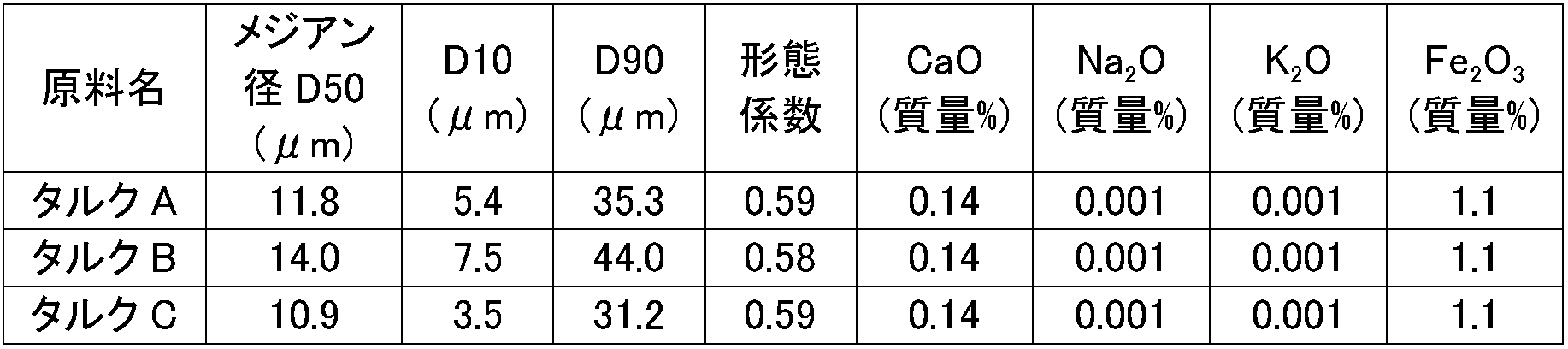
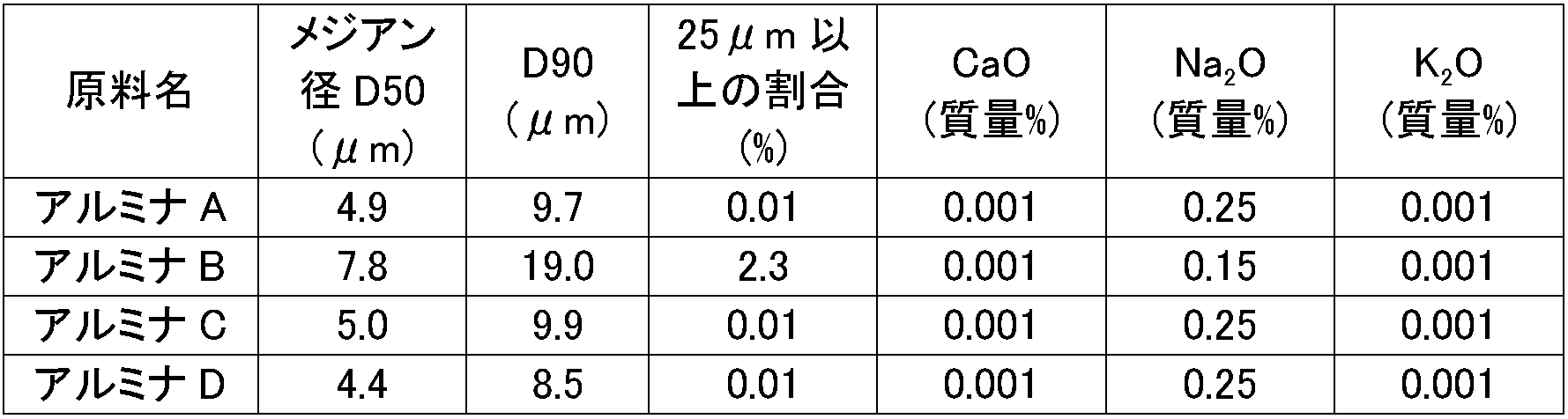
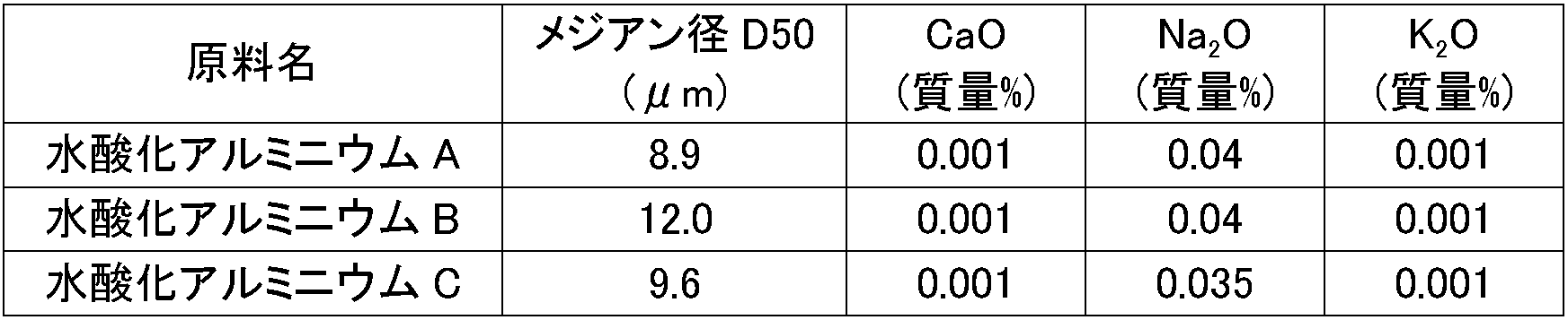

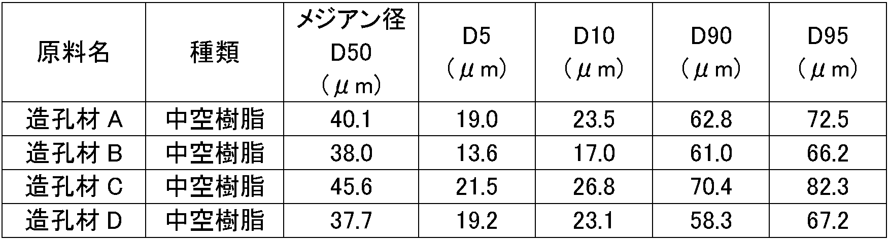

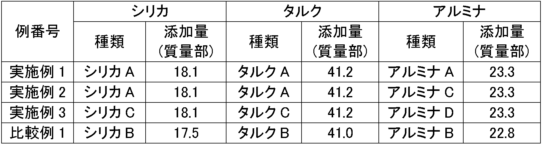


初期圧力損失は、圧力損失テストスタンドに固定したセラミックハニカムフィルタに、空気を流量10 Nm3/minで送り込み、流入側と流出側との差圧(圧力損失)で表した。圧力損失が、
1.0 kPaを越える場合を(×)、
0.8 kPaを超え1.0 kPa以下の場合を(△)、
0.6 kPaを超え0.8 kPa以下の場合を(○)、及び
0.6 kPa以下の場合を(◎)
として初期圧力損失を評価した。
PM捕集後圧力損失は、圧力損失テストスタンドに固定したセラミックハニカムフィルタに、空気流量10 Nm3/minで、平均粒径0.11μmの燃焼煤を1.3 g/hの速度で投入し、フィルタ体積1リットルあたりの煤付着量が2 gとなった時の流入側と流出側との差圧(圧力損失)で表した。圧力損失が、
1.5 kPaを越える場合を(×)、
1.3 kPaを超え1.5 kPa以下の場合を(△)、
1.0 kPaを超え1.3 kPa以下の場合を(○)、及び
1.0 kPa以下の場合を(◎)
として煤捕集圧力損失を評価した。
捕集開始初期の粒子数基準でのPM捕集率は、圧力損失テストスタンドに固定したセラミックハニカムフィルタに、空気流量10 Nm3/minで、平均粒径0.11μmの燃焼煤を1.3 g/hの速度で投入しながら、1分毎にハニカムフィルタに流入する燃焼煤の粒子数とハニカムフィルタから流出する燃焼煤の粒子数とをSMPS(Scanning Mobility Particle Sizer)(TIS社製モデル3936)を用いて計測し、投入開始40分後から41分後までの1分間にハニカムフィルタに流入する燃焼煤の粒子数Nin、及びハニカムフィルタから流出する燃焼煤の粒子数Noutから、式:(Nin-Nout)/Ninにより求めた。PM捕集率が、
98%以上の場合を(◎)、
96%以上98%未満の場合を(○)、
95%以上96%未満の場合を(△)、及び
95%未満の場合を(×)
としてPM捕集率を評価した。
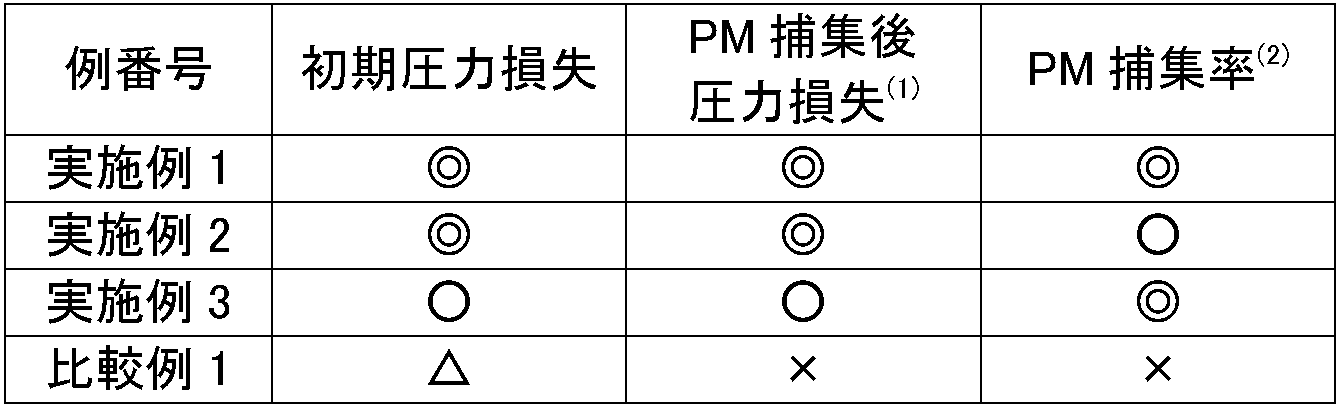
注(2):捕集開始初期の粒子数基準でのPM捕集率
Claims (7)
- 多孔質の隔壁で仕切られた多数の流路を有するセラミックハニカム構造体であって、
前記隔壁は、
(a)気孔率が50~60%、
(b)水銀圧入法により測定された細孔分布において、
(i)累積細孔容積が全細孔容積の5%となる細孔径d5が22μm以上55μm未満、
10%となる細孔径d10が15~35μm、
50%となる細孔径(メジアン細孔径)d50が10~20μm、
85%となる細孔径d85が5~9μm、
90%となる細孔径d90が3~8μm、
98%となる細孔径d98が2.5μm以下、
(d10-d90)/d50が1.3~1.8、
(d50-d90)/d50が0.45~0.75、及び
(d10-d50)/d50が0.75~1.1であり、
(ii)累積細孔容積が全細孔容積の20%となる細孔径d20の対数と80%となる細孔径d80の対数との差σ=log(d20)-log(d80)が0.39以下であることを特徴とするセラミックハニカム構造体。 - 請求項1に記載のセラミックハニカム構造体において、
累積細孔容積が全細孔容積の2%となる細孔径d2が75~250μm、及び20μm以上の細孔容積が0.12 cm3/g以下であることを特徴とするセラミックハニカム構造体。 - 請求項1又は2に記載のセラミックハニカム構造体において、前記気孔率が52~60%であることを特徴とするセラミックハニカム構造体。
- 請求項1~3のいずれかに記載のセラミックハニカム構造体において、前記メジアン細孔径d50が10~18μmであることを特徴とするセラミックハニカム構造体。
- 請求項1~4のいずれかに記載のセラミックハニカム構造体において、前記σが0.3以下であることを特徴とするセラミックハニカム構造体。
- セラミック原料及び中空の樹脂粒子からなる造孔材を含む坏土を所定の成形体に押出成形し、前記成形体を乾燥及び焼成する工程を有するセラミックハニカム構造体の製造方法であって、
前記坏土が、前記セラミック原料100質量%に対して3~9質量%の前記造孔材を含有し、
前記造孔材は、メジアン径D50が20~53μm、粒子径と累積体積との関係を示す曲線において、全体積の5%に相当する累積体積での粒子径D5が12~27μm、全体積の10%に相当する累積体積での粒子径D10が15~30μm、全体積の90%に相当する累積体積での粒子径D90が50~75μm、全体積の95%に相当する累積体積での粒子径D95が60~90μm、及びD50/(D90-D10)が0.85~1.30であり、
前記セラミック原料が、前記セラミック原料100質量%に対して15~25質量%のシリカ、40~43質量%のタルク及び15~30質量%のアルミナを含有し、
前記シリカは、メジアン径D50が15~30μm、D10が10~20μm、D90が40~60μm、5μm以下の粒子径を有する粒子の割合が1質量%以下、10μm以下の粒子径を有する粒子の割合が3質量%以下、100μm以上の粒子径を有する粒子の割合が3質量%以下、及び200μm以上の粒子径を有する粒子の割合が1質量%以下、粒度分布偏差SD[ただし、SD=log(D80)-log(D20)、D20は、粒子径と累積体積との関係を示す曲線において、全体積の20%に相当する累積体積での粒子径であり、D80は同じく全体積の80%に相当する累積体積での粒子径でありD20<D80である。]が0.4以下であり、
前記タルクは、メジアン径D50が5~15μm、D10が10μm以下、及びD90が25μm以上であり、
前記アルミナは、メジアン径D50が3~6μm、D90が20μm以下、及び25μm以上の粒子径を有する粒子の割合が0.4質量%以下であることを特徴とするセラミックハニカム構造体の製造方法。 - 請求項6に記載のセラミックハニカム構造体の製造方法において、前記坏土が、前記セラミック原料100質量%に対して3.5~8質量%の前記造孔材を含有することを特徴とするセラミックハニカム構造体の製造方法。
Priority Applications (6)
| Application Number | Priority Date | Filing Date | Title |
|---|---|---|---|
| US15/517,026 US10072543B2 (en) | 2015-03-24 | 2016-03-17 | Ceramic honeycomb structure and its production method |
| CN201680011395.2A CN107250083B (zh) | 2015-03-24 | 2016-03-17 | 陶瓷蜂窝结构体及其制造方法 |
| KR1020177022305A KR102439667B1 (ko) | 2015-03-24 | 2016-03-17 | 세라믹 허니컴 구조체 및 그의 제조 방법 |
| EP16768612.0A EP3275852B1 (en) | 2015-03-24 | 2016-03-17 | Ceramic honeycomb structure and method for producing same |
| JP2016539338A JP6004150B1 (ja) | 2015-03-24 | 2016-03-17 | セラミックハニカム構造体及びその製造方法 |
| US15/706,794 US10077693B2 (en) | 2015-03-24 | 2017-09-18 | Ceramic honeycomb structure and its production method |
Applications Claiming Priority (2)
| Application Number | Priority Date | Filing Date | Title |
|---|---|---|---|
| JP2015061265 | 2015-03-24 | ||
| JP2015-061265 | 2015-03-24 |
Related Child Applications (2)
| Application Number | Title | Priority Date | Filing Date |
|---|---|---|---|
| US15/517,026 A-371-Of-International US10072543B2 (en) | 2015-03-24 | 2016-03-17 | Ceramic honeycomb structure and its production method |
| US15/706,794 Division US10077693B2 (en) | 2015-03-24 | 2017-09-18 | Ceramic honeycomb structure and its production method |
Publications (1)
| Publication Number | Publication Date |
|---|---|
| WO2016152709A1 true WO2016152709A1 (ja) | 2016-09-29 |
Family
ID=56978675
Family Applications (1)
| Application Number | Title | Priority Date | Filing Date |
|---|---|---|---|
| PCT/JP2016/058467 Ceased WO2016152709A1 (ja) | 2015-03-24 | 2016-03-17 | セラミックハニカム構造体及びその製造方法 |
Country Status (6)
| Country | Link |
|---|---|
| US (2) | US10072543B2 (ja) |
| EP (1) | EP3275852B1 (ja) |
| JP (1) | JP6004150B1 (ja) |
| KR (1) | KR102439667B1 (ja) |
| CN (1) | CN107250083B (ja) |
| WO (1) | WO2016152709A1 (ja) |
Cited By (3)
| Publication number | Priority date | Publication date | Assignee | Title |
|---|---|---|---|---|
| WO2019189889A1 (ja) | 2018-03-29 | 2019-10-03 | 日立金属株式会社 | セラミックハニカムフィルタ |
| JP2020164408A (ja) * | 2019-03-28 | 2020-10-08 | 日本碍子株式会社 | セラミックス多孔体及びその製造方法、並びに集塵用フィルタ |
| JP2023148834A (ja) * | 2022-03-30 | 2023-10-13 | 日本碍子株式会社 | ハニカムフィルタ |
Families Citing this family (8)
| Publication number | Priority date | Publication date | Assignee | Title |
|---|---|---|---|---|
| WO2019188962A1 (ja) * | 2018-03-30 | 2019-10-03 | 日本碍子株式会社 | 膜フィルタ用基材及びその製造方法 |
| CN109296354A (zh) * | 2018-10-18 | 2019-02-01 | 中国石油化工股份有限公司 | 地层砂粒径参数计算方法及系统 |
| JP7097327B2 (ja) * | 2019-04-26 | 2022-07-07 | 株式会社Soken | 排ガス浄化フィルタ |
| JP7274395B2 (ja) * | 2019-10-11 | 2023-05-16 | 日本碍子株式会社 | ハニカム構造体 |
| JP7353218B2 (ja) * | 2020-03-02 | 2023-09-29 | 日本碍子株式会社 | ハニカムフィルタ |
| JP7449721B2 (ja) * | 2020-03-02 | 2024-03-14 | 日本碍子株式会社 | ハニカムフィルタ |
| JP7481281B2 (ja) | 2021-02-25 | 2024-05-10 | 日本碍子株式会社 | 多孔質ハニカム構造体及びその製造方法 |
| CN113731062A (zh) * | 2021-09-16 | 2021-12-03 | 上海洁昊环保股份有限公司 | 一种透壁式滤芯及除尘装置 |
Citations (4)
| Publication number | Priority date | Publication date | Assignee | Title |
|---|---|---|---|---|
| JPS61129015A (ja) * | 1984-11-24 | 1986-06-17 | Nippon Denso Co Ltd | 排出ガス浄化用フイルタおよびその製造方法 |
| WO2011027837A1 (ja) * | 2009-09-04 | 2011-03-10 | 日立金属株式会社 | セラミックハニカム構造体及びその製造方法 |
| WO2011102487A1 (ja) * | 2010-02-22 | 2011-08-25 | 日立金属株式会社 | セラミックハニカム構造体及びその製造方法 |
| WO2014163036A1 (ja) * | 2013-04-02 | 2014-10-09 | 日立金属株式会社 | セラミックハニカム構造体及びその製造方法 |
Family Cites Families (17)
| Publication number | Priority date | Publication date | Assignee | Title |
|---|---|---|---|---|
| JP2003040687A (ja) | 2000-06-30 | 2003-02-13 | Ngk Insulators Ltd | ハニカムセラミックス構造体とその製造方法 |
| JP4094830B2 (ja) * | 2000-11-24 | 2008-06-04 | 日本碍子株式会社 | 多孔質ハニカムフィルター及びその製造方法 |
| US6827754B2 (en) * | 2001-09-13 | 2004-12-07 | Hitachi Metals, Ltd. | Ceramic honeycomb filter |
| EP1316686B1 (en) * | 2001-12-03 | 2007-09-05 | Hitachi Metals, Ltd. | Ceramic honeycomb filter |
| EP1515787A4 (en) | 2002-06-26 | 2006-11-29 | Corning Inc | ALUMINUM AND MAGNESIUM SILICATE TYPE STRUCTURES FOR DPF APPLICATIONS |
| JP4750343B2 (ja) * | 2002-10-23 | 2011-08-17 | 日本碍子株式会社 | 多孔質ハニカム構造体の製造方法、及びハニカム成形体 |
| JP4577752B2 (ja) | 2003-06-06 | 2010-11-10 | 日立金属株式会社 | セラミックハニカムフィルタ |
| US7520911B2 (en) | 2005-11-30 | 2009-04-21 | Corning Incorporated | Porous cordierite ceramic honeycomb article with improved strength and method of manufacturing same |
| CN101400623B (zh) | 2006-03-17 | 2012-05-23 | 日本碍子株式会社 | 蜂窝状结构体的制造方法 |
| US7648548B2 (en) * | 2006-05-10 | 2010-01-19 | Corning Incorporated | High porosity cordierite composition |
| US8500840B2 (en) * | 2007-10-12 | 2013-08-06 | Hitachi Metals, Ltd. | Cordierite-based ceramic honeycomb filter and its production method |
| US8119234B2 (en) | 2008-02-29 | 2012-02-21 | Corning Incorporated | Anisotropic porous ceramic article and manufacture thereof |
| US8501296B2 (en) * | 2008-02-29 | 2013-08-06 | Corning Incorporated | Stabilized low-microcracked ceramic honeycombs and methods thereof |
| JP2011515309A (ja) * | 2008-02-29 | 2011-05-19 | コーニング インコーポレイテッド | 粉砕された堅果の殻を用いたハニカム製造方法および該方法により生成されたハニカム体 |
| CN102089058B (zh) * | 2008-07-28 | 2014-03-12 | 日立金属株式会社 | 陶瓷蜂窝结构体及其制造方法 |
| JP5486539B2 (ja) * | 2011-03-30 | 2014-05-07 | 日本碍子株式会社 | ハニカム構造体及びその製造方法 |
| CN105392759B (zh) * | 2013-09-24 | 2018-01-26 | 日立金属株式会社 | 陶瓷蜂窝结构体及其制造方法 |
-
2016
- 2016-03-17 JP JP2016539338A patent/JP6004150B1/ja active Active
- 2016-03-17 KR KR1020177022305A patent/KR102439667B1/ko active Active
- 2016-03-17 US US15/517,026 patent/US10072543B2/en active Active
- 2016-03-17 WO PCT/JP2016/058467 patent/WO2016152709A1/ja not_active Ceased
- 2016-03-17 CN CN201680011395.2A patent/CN107250083B/zh active Active
- 2016-03-17 EP EP16768612.0A patent/EP3275852B1/en active Active
-
2017
- 2017-09-18 US US15/706,794 patent/US10077693B2/en active Active
Patent Citations (4)
| Publication number | Priority date | Publication date | Assignee | Title |
|---|---|---|---|---|
| JPS61129015A (ja) * | 1984-11-24 | 1986-06-17 | Nippon Denso Co Ltd | 排出ガス浄化用フイルタおよびその製造方法 |
| WO2011027837A1 (ja) * | 2009-09-04 | 2011-03-10 | 日立金属株式会社 | セラミックハニカム構造体及びその製造方法 |
| WO2011102487A1 (ja) * | 2010-02-22 | 2011-08-25 | 日立金属株式会社 | セラミックハニカム構造体及びその製造方法 |
| WO2014163036A1 (ja) * | 2013-04-02 | 2014-10-09 | 日立金属株式会社 | セラミックハニカム構造体及びその製造方法 |
Non-Patent Citations (1)
| Title |
|---|
| See also references of EP3275852A4 * |
Cited By (9)
| Publication number | Priority date | Publication date | Assignee | Title |
|---|---|---|---|---|
| WO2019189889A1 (ja) | 2018-03-29 | 2019-10-03 | 日立金属株式会社 | セラミックハニカムフィルタ |
| JPWO2019189889A1 (ja) * | 2018-03-29 | 2021-05-13 | 日立金属株式会社 | セラミックハニカムフィルタ |
| US11383190B2 (en) | 2018-03-29 | 2022-07-12 | Hitachi Metals, Ltd. | Ceramic honeycomb filter |
| JP7180669B2 (ja) | 2018-03-29 | 2022-11-30 | 日立金属株式会社 | セラミックハニカムフィルタ |
| JP2020164408A (ja) * | 2019-03-28 | 2020-10-08 | 日本碍子株式会社 | セラミックス多孔体及びその製造方法、並びに集塵用フィルタ |
| JP7289813B2 (ja) | 2019-03-28 | 2023-06-12 | 日本碍子株式会社 | セラミックス多孔体及びその製造方法、並びに集塵用フィルタ |
| JP2023148834A (ja) * | 2022-03-30 | 2023-10-13 | 日本碍子株式会社 | ハニカムフィルタ |
| JP7799541B2 (ja) | 2022-03-30 | 2026-01-15 | 日本碍子株式会社 | ハニカムフィルタ |
| US12636603B2 (en) | 2022-03-30 | 2026-05-26 | Ngk Insulators, Ltd. | Honeycomb filter |
Also Published As
| Publication number | Publication date |
|---|---|
| CN107250083B (zh) | 2020-10-16 |
| EP3275852A4 (en) | 2018-11-21 |
| CN107250083A (zh) | 2017-10-13 |
| JPWO2016152709A1 (ja) | 2017-04-27 |
| US10072543B2 (en) | 2018-09-11 |
| KR20170129694A (ko) | 2017-11-27 |
| US20180016955A1 (en) | 2018-01-18 |
| EP3275852A1 (en) | 2018-01-31 |
| EP3275852B1 (en) | 2022-01-12 |
| US10077693B2 (en) | 2018-09-18 |
| KR102439667B1 (ko) | 2022-09-01 |
| US20170298794A1 (en) | 2017-10-19 |
| JP6004150B1 (ja) | 2016-10-05 |
Similar Documents
| Publication | Publication Date | Title |
|---|---|---|
| JP5751398B1 (ja) | セラミックハニカム構造体及びその製造方法 | |
| JP6004151B1 (ja) | セラミックハニカム構造体 | |
| JP6004150B1 (ja) | セラミックハニカム構造体及びその製造方法 | |
| JP5725247B2 (ja) | セラミックハニカム構造体の製造方法 | |
| JP5835395B2 (ja) | セラミックハニカム構造体の製造方法 | |
| JP5751397B1 (ja) | コーディエライト質セラミックハニカム構造体及びその製造方法 | |
| WO2021075211A1 (ja) | セラミックハニカム構造体及びその製造方法 |
Legal Events
| Date | Code | Title | Description |
|---|---|---|---|
| ENP | Entry into the national phase |
Ref document number: 2016539338 Country of ref document: JP Kind code of ref document: A |
|
| 121 | Ep: the epo has been informed by wipo that ep was designated in this application |
Ref document number: 16768612 Country of ref document: EP Kind code of ref document: A1 |
|
| WWE | Wipo information: entry into national phase |
Ref document number: 15517026 Country of ref document: US |
|
| ENP | Entry into the national phase |
Ref document number: 20177022305 Country of ref document: KR Kind code of ref document: A |
|
| NENP | Non-entry into the national phase |
Ref country code: DE |
|
| REEP | Request for entry into the european phase |
Ref document number: 2016768612 Country of ref document: EP |