WO2016152703A1 - 眼内レンズ - Google Patents
眼内レンズ Download PDFInfo
- Publication number
- WO2016152703A1 WO2016152703A1 PCT/JP2016/058457 JP2016058457W WO2016152703A1 WO 2016152703 A1 WO2016152703 A1 WO 2016152703A1 JP 2016058457 W JP2016058457 W JP 2016058457W WO 2016152703 A1 WO2016152703 A1 WO 2016152703A1
- Authority
- WO
- WIPO (PCT)
- Prior art keywords
- intraocular lens
- support portion
- soft
- end portion
- tip
- Prior art date
- Legal status (The legal status is an assumption and is not a legal conclusion. Google has not performed a legal analysis and makes no representation as to the accuracy of the status listed.)
- Ceased
Links
Images






Classifications
-
- A—HUMAN NECESSITIES
- A61—MEDICAL OR VETERINARY SCIENCE; HYGIENE
- A61F—FILTERS IMPLANTABLE INTO BLOOD VESSELS; PROSTHESES; DEVICES PROVIDING PATENCY TO, OR PREVENTING COLLAPSING OF, TUBULAR STRUCTURES OF THE BODY, e.g. STENTS; ORTHOPAEDIC, NURSING OR CONTRACEPTIVE DEVICES; FOMENTATION; TREATMENT OR PROTECTION OF EYES OR EARS; BANDAGES, DRESSINGS OR ABSORBENT PADS; FIRST-AID KITS
- A61F2/00—Filters implantable into blood vessels; Prostheses, i.e. artificial substitutes or replacements for parts of the body; Appliances for connecting them with the body; Devices providing patency to, or preventing collapsing of, tubular structures of the body, e.g. stents
- A61F2/02—Prostheses implantable into the body
- A61F2/14—Eye parts, e.g. lenses or corneal implants; Artificial eyes
- A61F2/16—Intraocular lenses
Definitions
- the present invention relates to an intraocular lens, and more particularly, to an intraocular lens that can be used for various techniques such as in-the-bag, out-the-bag, sewing fixation, and intra-scleral fixation.
- the lens becomes cloudy due to cataracts
- the visual acuity is restored by a surgical procedure in which an intraocular lens, which is an artificial lens, is inserted into the eye instead of the clouded lens.
- An intraocular lens implanted into the eye during cataract surgery is composed of an optical part (lens part) having an optical lens function instead of a crystalline lens and a support part that supports the optical part.
- this type of intraocular lens is housed inside the lens capsule that remains after the lens is removed.
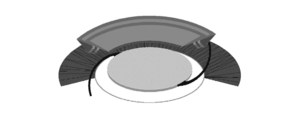
- a cataract operation in-the-bag bag as shown in FIG. 1 is performed.
- a cataract operation (out-the-blade bag) is performed in which an intraocular lens is placed in such a manner that the support portion is fitted into the ciliary groove while being placed on the cornea side as viewed from the lens capsule (FIG. 2).
- This sewing fixation mainly includes the following techniques, that is, ciliary groove sewing (FIG. 3), ciliary body flat part sewing, and sewing to the sclera.
- intrascleral fixation is a technique of embedding the tip of the support part of the intraocular lens in the sclera.
- the intraocular lens can be placed more stably (eg, the eccentricity and inclination of the optical part can be suppressed) than the conventional technique of sewing.
- the eccentricity and inclination of the optical unit are collectively referred to as “eccentric inclination”.
- sewing is not essential, and the burden on the operator and the patient undergoing surgery can be significantly reduced.
- the present inventor performs not only the description in Patent Document 1 but also a variety of commercially available intraocular lenses by performing a test (tensile test) on the assumption that intrascleral fixation has been performed, and performs intrascleral fixation.
- the problem at the time was identified.
- the intraocular lens capable of intrascleral fixation has seemingly contradictory performances such as "specialization of performance for intrascleral fixation” and "general versatility for a variety of surgical procedures".
- the inventor is urged to provide something.
- An object of the present invention is to provide an intraocular lens that is specialized in performance for intrascleral fixation and also has versatility for a wide variety of surgical procedures.
- the present inventor has studied a method for solving the above-described problems, and further performed the above various tests.
- tests were performed on various known intraocular lenses.
- the configuration of the present invention described below has been adopted.
- the first aspect of the present invention is: A soft optical part having a lens function; A wide soft support portion extending from the optical portion and integrally formed with the optical portion and a base end; A hard support portion connected at the base end with the soft support portion and extended in the extending direction of the soft support portion; With In the intraocular lens, the maximum width of the distal end portion of the hard support portion is a narrow shape of 0.3 mm or less.
- a second aspect of the present invention is the invention according to the first aspect, The hard support portion further includes a middle base end portion connected to the wide soft support portion, and the base end portion and the narrow tip end portion are connected.
- a third aspect of the present invention is the invention according to the first or second aspect, The maximum width of the tip portion of the hard support portion is a narrow shape of 0.2 mm or less.
- a fourth aspect of the present invention is the invention according to any one of the first to third aspects, The distal end portion of the hard support portion is warped so as to face the optical portion.
- a fifth aspect of the present invention is the invention according to any one of the first to fourth aspects, wherein: The hard support portion is provided with a constriction.
- an intraocular lens having versatility for a wide variety of surgical procedures while being specialized in performance for intrascleral fixation.
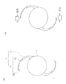
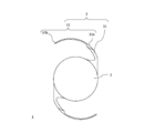
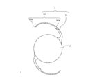
- FIG. 6 is a schematic plan view showing a preferable example (warp shape) of an intraocular lens in the present embodiment.
- FIG. 6A is a view before inserting the intraocular lens into the lens capsule, and FIG. FIG.
- Intraocular lens A
- Optical part B
- Support part B-1) Soft support part
- Hard support part B-2-1
- Base end part B-2-2
- Tip part B
- Manufacturing method of intraocular lens 3.
- Use of intraocular lens 4. Effects of the embodiment Modified example
- the tip of the support part is too wide to be suitable for intrascleral fixation, and “specification of performance for intrascleral fixation” “ In order to solve the seemingly contradictory problem of “general versatility for a wide variety of surgical methods”, there are a number of opportunities for selecting the configuration of the intraocular lens described in the document from among the numerous intraocular lenses. Not yet publicly known.
- the “tip” refers to the side away from the optical unit when viewed from the center of the optical unit
- the “base” refers to the side closer to the optical unit. Point to.
- width refers to the length of the diagonal of the rectangle
- width refers to the major axis.
- width refers to the diameter.
- the width in plan view for the purpose of illustrating the case where the cross section of each part is substantially rectangular.
- the outer side of a support part (a side far from the curve center of a support part) which opposes the arbitrary points inside a support part (side near the curve center of a support part). The distance between these points (the distance between points X and X ′ in FIG. 5 described later).
- From an arbitrary point on the inner side of the support portion like a point Y or a point Z of the support portion in FIG. It is the distance between the closest part (point Y ′ and point Z ′) on the side farther from the center of curvature.
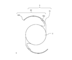
- Intraocular lens 1> As shown in FIG. 5, the intraocular lens 1 in this embodiment is roughly provided with an optical unit 2 having a lens function and a support unit 3 that supports the optical unit 2.
- FIG. 5 is a schematic view showing the intraocular lens 1 in the present embodiment, in which FIG. 5 (a) is a plan view and FIG. 5 (b) is a side view.
- FIG. 5 (a) is a plan view
- FIG. 5 (b) is a side view.
- the optical unit 2 is a relatively soft portion having a lens function, and is formed in a convex lens shape having a circular shape in plan view.
- the diameter of the optical unit 2 may be set to any size as long as it is a size suitable for inserting the intraocular lens 1 into the lens capsule in the eye.
- the diameter D of the optical unit 2 is preferably set in a range of 5 mm to 7 mm, and more preferably set to 6.5 mm.
- the thickness of the optical unit 2 may be set according to a desired refractive index or the like.
- the optical unit 2 is made of a soft material that allows the optical unit 2 to be folded.
- the term “foldable” described here is used to mean that the intraocular lens 1 including the optical unit 2 can be folded in at least two. Therefore, the soft material constituting the optical unit 2 is a material having a high degree of flexibility enough to fold the optical unit 2.
- soft materials such as silicone resin, acrylic resin, hydrogel, and urethane resin can be used.
- Support part 3 The support part 3 is formed in a state extending outward from the outer peripheral part of the optical part 2.
- the support unit 3 supports the optical unit 2 when the intraocular lens 1 is inserted into the eye.
- Two support portions 3 are formed on one intraocular lens 1.
- Each support portion 3 draws an arc in a counterclockwise direction in the drawing from a portion where an axis passing through the center C of the optical portion 2 (indicated by a one-dot chain line in the figure) intersects the outer peripheral portion of the optical portion 2. It extends to.
- Each support part 3 has the following common structure.
- the support part 3 extends in an arm shape outward from the outer peripheral part of the optical part 2.
- the support part 3 extends from the optical part 2 and is integrally formed at the base end with the optical part 2, and a wide soft support part 31 is connected to the soft support part 31 at the base end and is softly supported.
- a hard support portion 32 extended in the extending direction of the portion 31.
- the main part of the support part 3 is composed of a soft support part 31, and the tip part excluding this is composed of a hard support part 32.
- the tip of the support portion 3 is not J-shaped as described in Patent Document 1. It is what you point to.
- the tip portion 32b has a warped shape. If there is, it belongs to this embodiment.
- the outer surface of the support portion 3 draws a smoothly continuous arc from the soft support portion 31 to the hard support portion 32.
- the soft support portion 31 and the hard support portion 32 are sectioned using the arc line as a boundary line when an arc line having a radius R is drawn from the center C of the optical unit 2. That is, the portion inside the arc line having the radius R is the soft support portion 31, and the portion outside the arc line having the radius R is the hard support portion 32.
- the two support portions 3 have the same configuration and are arranged so as to be point-symmetric when viewed from the center C of the optical portion 2. For this reason, the reference numerals in the figure are attached only to one support part 3.
- the soft support portion 31 is configured to be elastically deformable in the radial direction of the optical portion 2.
- the soft support portion 31 extends in a slender shape as a whole, and the material constituting the soft support portion 31 also has appropriate flexibility.
- the soft support portion 31 is integrally formed of the same soft material as that of the optical portion 2 described above.
- integrated molding means that the optical part 2 and the soft support part 31 are integrally formed from the same member, and the optical part 2 and the soft support part 31 are separately formed. It is not formed as a member and connected.
- the soft support is performed according to the external force.
- the part 31 can be elastically deformed in a direction approaching the optical part 2.
- the intraocular lens 1 receives an external force that moves away from the center C of the optical part 2 through the hard support part 32 during sewing fixation or intrascleral fixation
- the soft support part 31 optically follows the external force. It can be elastically deformed in a direction away from the portion 2.
- the soft support portion 31 has a base end portion 32a (base portion) that is wide at the foot and is connected to the optical portion 2 at the widest portion. Further, the soft support portion 31 extends from the wide base end portion 32a so as to draw a circular arc obliquely outward.
- the tip portion (the portion on the side opposite to the root portion) of the soft support portion 31 is formed to be slightly wider. Note that the width of the soft support portion 31 is gradually reduced from the base end portion 32a of the soft support portion 31 to the distal end portion.
- the hard support part 32 is made of a material having a hardness different from that of the optical part 2 and the soft support part 31 described above. Specifically, the hard support portion 32 is made of a hard material harder than the soft support portion 31. As a hard material applied to the hard support portion 32, any material can be used as long as it can guarantee a strength enough to prevent the portion from being broken even if the suture is tied to the hard support portion 32. Specifically, for example, a hard resin material such as PMMA (polymethyl methacrylate) can be used. The end of the hard support portion 32 is slightly rounded so as not to damage the eyeball tissue even if it contacts the eyeball tissue. Moreover, the soft support part 31 and the hard support part 32 which comprise the support part 3 are structurally integrated only by the material of each site
- the hard support portion 32 includes a medium-width base end portion 32a connected to the wide soft support portion 31 and a narrow end (in other words, an ultrafine shape) having a maximum width of 0.3 mm or less. Part 32b.
- the base end portion 32a constituting the hard support portion 32 is a portion connecting the soft support portion 31 described above and the distal end portion 32b having a narrow shape which will be described later, which is another portion constituting the hard support portion 32. There is a portion for smoothly changing the width when viewed from the entire support portion 3. Specifically, based on the role of gradually narrowing the hard support portion 32 toward the distal end side by changing the curvature of the inner curvature while keeping the curvature of the outer curvature of the support portion 3 as it is. The end 32a bears.
- the tip portion 32 b is a portion located at the tip of the hard support portion 32.
- the maximum width of the tip 32b is 0.3 mm or less, and has a narrow shape (in other words, an ultrafine shape).
- the hard tip end portion 32b has a narrow shape, thereby achieving various synergies. An effect is obtained. Details will be described below.
- the distal end portion 32b can be easily inserted into the sclera when performing intrascleral fixation.
- a tunnel-like hole formed in the sclera in the circumferential direction is used by using a technique similar to that described in [0004] and [0029] to [0034] of Patent Document 1. Insert the tip 32b.
- the maximum width of the distal end portion 32b is a very narrow shape of 0.3 mm or less, the ease of insertion of the distal end portion 32b into the tunnel-shaped hole portion is remarkably improved, and the surgical procedure by the operator is improved. The burden is significantly reduced.
- the intraocular lens 1 shows surprisingly high stability in terms of stability after intrascleral fixation, that is, in terms of the difficulty of causing eccentric inclination.
- the intraocular lens 1 is fixed by the tip portions 32b of the two support portions 3, the optical portion 2 in which the tip portion 32b is suspended in a very thick shape is considered to be a very thin tip portion 32b. It is considered that the optical unit 2 is more stably disposed than the optical unit 2 to be hung.
- the intraocular lens 1 in the present embodiment is a lens specialized for a specific situation of intrascleral fixation, there are some aspects where such a conventional idea is not valid.
- the intraocular lens 1 is placed under a certain special situation in which the distal end portion 32b is sandwiched between meat layers constituting the sclera.
- the narrow end portion 32b is more easily wrapped in the meat layer than the wide end portion 32b.
- the maximum width of the distal end portion 32b is 0.3 mm or less, it is possible to effectively suppress the occurrence of the eccentric inclination in the scleral fixation because the shape is extremely narrow in other words.
- the ease of inserting the tip 32b into the tunnel-shaped hole is greatly improved.
- the tip 32b has a very narrow shape with a maximum width of 0.3 mm or less, it can be combined with the various configurations described above to achieve a technique other than intrascleral fixation, that is, an insole bag, an outsole It also has a positive effect in various techniques such as bag and sewing fixation.
- the intraocular lens 1 is inserted into the capsular bag, and the support 3 is fitted near the equator of the capsular bag.
- the support 3 is very easily and stably fitted in the vicinity of the equator of the lens capsule. This leads to the stable placement of the optical unit 2 in the intraocular lens 1 and, in turn, makes it difficult for eccentric tilt to occur.
- the support portion 3 is fitted into the ciliated groove, so that the maximum width of the tip 32b is 0.3 mm or less, as in the case of the in-the-bag bag,
- the support part 3 fits very easily and stably. This leads to the stable placement of the optical unit 2 in the intraocular lens 1 and, in turn, makes it difficult for eccentric tilt to occur.
- the width of the distal end portion 32b is a very narrow shape of 0.3 mm or less, it is convenient when sewing each tissue of the eye and the distal end portion 32b.
- the maximum width of the distal end portion 32b is large, the eye tissue must be sutured in a wide range according to the width of the distal end portion 32b, which increases the burden on the patient. .
- the maximum width of the tip end portion 32b is 0.3 mm or less, the tip end portion 32b can be locally sewn tightly, and the sewing thread will not easily come off.
- the maximum width of the tip end portion 32b is large, it is difficult to collect the winding portions at one place when the sewing thread is wound around the tip end portion 32b, and the tip end portion 32b cannot be locally stitched.
- tip part 32b in this embodiment may be arbitrary as long as it is a distance which can perform intrascleral fixation from the forefront of the hard support part 32.
- the maximum width of the tip portion 32b is 0.3 mm or less.
- the preferable shape is a shape in which the distal end portion 32b is warped toward the optical unit 2 (FIG. 6A).
- the tip 32b is warped toward the optical unit 2 as compared to the portion of the support 3 up to the tip 32b.
- this shape is simply referred to as a “warped shape”.
- the warp is closer to the optical unit 2 than the original curved shape of the base end portion 32a, and the outer curve of the support portion 3 due to the warp is warped. It is less than 90 ° (preferably 45 ° or less, more preferably 30 ° or less). That is, the J-shape as described in Patent Document 1 is not included in the “warp” in the present embodiment.
- the reason why the warp shape is adopted for the distal end portion 32b is that the intraocular lens 1 of the present embodiment is applied to the in-the-bag bag.
- the intraocular lens 1 is compressed by the lens capsule, and pressure is transmitted from the vicinity of the equator of the lens capsule to the distal end portion 32b.
- a portion having a warped shape at the distal end portion 32b is deformed along the lens capsule. That is, by inserting the intraocular lens 1 into the capsular bag, the contact area between the capsular bag and the support unit 3 can be increased, and the intraocular lens 1 (optical unit 2) can be stably disposed. As a result, the occurrence of the eccentric inclination can be more efficiently suppressed. Note that this deformation is possible because the tip 32b has a very narrow shape with a maximum width of 0.3 mm or less.
- the specific position of the warped shape in the present embodiment is, as a preferred example, a portion from the most distal end of the hard support portion 32 to at least 3 mm, more preferably at least 5 mm, and even more preferably at least It is preferable that a 7 mm portion, and preferably a 10 mm portion from the forefront, be warped.
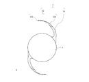
- Another preferred shape is to provide a constriction at the tip 32b (FIG. 7).
- the term “bundling” refers to a state in which the width is wider on both sides of the portion to be constricted and the portion to be constricted is relatively narrow.
- the constriction mentioned here may be formed by narrowing the width of the portion to be constricted, or the constriction may be formed by providing a wide portion on both sides of the constricted portion.
- constriction is formed on the distal end portion 32b
- it may be formed on the proximal end portion 32a. If it is advantageous to sew in the vicinity of the distal end portion 32b according to the technique, a constriction may be formed in the distal end portion 32b. Further, it is preferable to provide the constriction on the inner side of the curve in terms of facilitating the surgical procedure, but it may be provided on the outer side of the curve or on both sides.
- the maximum width of the tip 32b it is preferable if it is 0.2 mm or less. If the maximum width of the tip 32b is narrowed, the effects listed above are further increased.
- the lower limit is not particularly specified as long as the above effect can be obtained, but may be any, but if exemplified, 0.1 mm or more and 0.15 mm or more may be mentioned.
- the distal end portion 32b may gradually decrease in width toward the forefront within a range of 0.3 mm or less, or may have a predetermined constant width of 0.3 mm or less.
- the total length of the intraocular lens 1 is 13.5 mm
- the width of the distal end portion of the soft support portion 31 is 0 from the proximal end (base) to the distal end.
- the width gradually decreases from 0.5 mm to 0.4 mm
- the width of the tip 32b of the hard support portion 32 is 0.1 mm.
- the horizontal distance between the geometric center of the optical unit 2 and the distal end portion 32b in a state where the outer shapes of the base end portions (bases) of the two soft support portions 31 are aligned in the vertical direction is set to 1 mm.
- the width of the distal end portion 32b of the hard support portion 32 is 0.1 mm
- the width of the base end portion (base) of the soft support portion 31 is 0.15 mm.
- Manufacturing method of intraocular lens 1 Then, the manufacturing method of the intraocular lens 1 which concerns on this embodiment is demonstrated.
- the manufacturing method of the intraocular lens 1 can be considered mainly divided into three steps. Hereinafter, it demonstrates according to the flow of a process.
- annular hard material portion 100 is obtained by a known molding method using, for example, PMMA (hard material).
- a circular hole 110 is formed in the center of the hard material portion 100.
- a raw material liquid 200 that becomes, for example, a soft acrylic (soft material) after polymerization is injected into the circular hole 110 of the hard material portion 100 to complete the polymerization.
- the soft material portion 250 having a circular shape in plan view is formed inside the hard material portion 100.
- the lens material 300 having a structure in which the hard material portion 100 and the soft material portion 250 are integrated is obtained.
- the surface shape of the lens material 300 is adjusted to match the surface shapes of the optical unit 2 and the support unit 3. Specifically, by performing surface forming processing on the front and back surfaces of the lens material 300 using a precision lathe device, the convex curved surface of the optical unit 2, the slope of the base portion of the support unit 3, and other flat surfaces are obtained. In addition, the surface shape of the lens material 300 is adjusted. Thereby, a disk-shaped intermediate member (processed product of lens material) 350 reflecting the shape of the front and back surfaces of the intraocular lens 1 is obtained.
- the outer shape of the intermediate member 350 is adjusted according to the outer shapes of the optical unit 2 and the support unit 3. Specifically, an unnecessary portion as the intraocular lens 1 is removed from the intermediate member 350 by performing an outer shape process such as a milling process on the intermediate member 350. Thereafter, polishing is performed on necessary portions.
- the rotationally symmetric disk-shaped lens material 300 By using the rotationally symmetric disk-shaped lens material 300, the eccentric inclination can be effectively suppressed. This is because the intraocular lens 1 manufactured by the above manufacturing method has higher symmetry than the case where the support unit 3 is formed as a separate member from the optical unit 2 and the support unit 3 is attached to the optical unit 2.
- the two support portions 3 are provided to face each other with the optical portion 2 interposed therebetween, when the two support portions 3 are pulled away (that is, when sewn or fixed in the sclera), the balance is good.
- the support part 3 can be pulled, and the stability of the optical part 2 pulled by the support part 3 is greatly improved.
- the two support portions 3 are pressed toward each other (that is, in the case of the in-user bag and the out-user bag).
- a scleral incision is formed from one location below the scleral half-layer valve in the sclera, and an intrascleral tunnel is formed in the circumferential direction about the visual axis.
- the intraocular lens 1 is inserted into the eye by an injector or the like through an incision formed in the cornea, for example. At that time, the distal end portion 32b of the one support portion 3 is partially exposed to the outside from the incision of the cornea.
- the distal end portion 32b of the other support portion 3 inserted into the eye is pulled out from the posterior chamber through a scleral incision with an instrument such as forceps, and the lower part of the scleral half-layer valve To expose outside the eye. Then, the distal end portion 32b exposed to the outside of the eye is inserted into the intrascleral tunnel formed above with a tool such as forceps.
- the two scleral half-layer valves are closed.
- the intrascleral tunnel tightens the support part 3 to restrain and hold the support part 3 in the intrascleral tunnel, and the intraocular lens 1 is fixed in the eye without sewing.
- the intrascleral fixation can be fixed without sewing, but it does not deny that it is sewn. In order to make the fixation firm, it is possible to carry out several stitches.
- an intraocular lens 1 that is specialized in suppressing eccentric inclination, which is a major problem for intrascleral fixation (ie, an intraocular lens 1 specialized in intrascleral fixation).
- the intraocular lens 1 according to the present embodiment specialized for intrascleral fixation is possessed as an inventory, it is possible to cope with surgical procedures other than intrascleral fixation. Then, the burden on the stock is reduced for the surgeon, and convenience is improved. As a result, even the intraocular lens 1 specialized for intrascleral fixation can satisfy the hidden demand for the intraocular lens 1 that can handle other surgical methods.
- the intraocular lens 1 according to the present embodiment even when an operation method other than intrascleral fixation is applied, deformation of the lens capsule itself can be suppressed, and the optical unit 2 of the intraocular lens 1 can be suppressed. Can be suppressed.
- an intraocular lens 1 that is specialized in performance for intrascleral fixation and has versatility for a wide variety of surgical procedures.
- Base end 32a and tip 32b In this embodiment, the case where the base end part 32a and the front-end
- the warped shape of the distal end portion 32b is given as a preferred modification to the present invention.
- the “warp shape” described above can be an independent invention.
- the intraocular lens 1 is compressed by the lens capsule, and when pressure is transmitted from the vicinity of the equator of the lens capsule to the tip 32b, In some cases, the arrangement becomes unstable and an eccentric inclination occurs (problem). Therefore, as shown in FIG. 6B, a warp shape is provided at the tip 32b (means).
- each of the two support portions 3 is connected to the optical portion 2 only at one end.
- the hard support portion 32 is formed relatively long. This makes it easier to perform a surgical procedure when performing intrascleral fixation.
- the total length of the intraocular lens 1 is 13.5 mm
- the width of the distal end portion of the soft support portion 31 is 0.4 mm
- the width of the distal end portion 32b of the hard support portion 32 is 0.13 mm.
- the horizontal distance between the geometric center of the optical unit 2 and the distal end portion 32b in a state where the outer shapes of the base end portions (bases) of the two soft support portions 31 are aligned in the vertical direction is set to 4.2 mm.
- the above-described constriction is provided inside the curved shape of the hard support portion 32.
- the hard support portion 32 is formed relatively short. In this way, the technique of the in-the-bag can be facilitated while specializing in intrascleral fixation.
- the total length of the intraocular lens 1 is 13.5 mm
- the width of the distal end portion of the soft support portion 31 is 0.4 mm
- the width of the distal end portion 32b of the hard support portion 32 is 0.13 mm.
- the horizontal distance between the geometric center of the optical unit 2 and the distal end portion 32b in a state where the outer shapes of the base end portions (bases) of the two soft support portions 31 are aligned in the vertical direction is 3.4 mm.
- the base end portion (base) of the soft support portion 31 is made relatively narrow and the base end portion 32a of the hard support portion 32 is provided with a warp shape at the tip end portion 32b as described above. Is formed relatively long. The effects described above can be obtained with respect to the warped shape. In addition, it has a beneficial effect when performing in-the-bag techniques. After the support part 3 is folded and the intraocular lens 1 is inserted into the crystalline lens capsule, when the intraocular lens 1 is deployed, the initial deployment direction of the support part 3 can be set to the horizontal direction. Can be deployed properly.
- the total length of the intraocular lens 1 is 13.5 mm
- the width of the distal end portion of the soft support portion 31 is 0.43 mm
- the width of the distal end portion 32b of the hard support portion 32 is 0.13 mm
- the distal end of the constricted vicinity The width close to the portion 32b is 0.147 mm.
- the horizontal distance between the geometric center of the optical unit 2 and the distal end portion 32b in a state where the outer shapes of the base end portions (bases) of the two soft support portions 31 are aligned in the vertical direction is set to 3.1 mm.
- the mode shown in FIG. 12 is based on the mode shown in FIG.
- the width of the distal end portion 32b of the hard support portion 32 is made relatively wide.
- strength of the support part 3 can be improved and the possibility of the failure
- the total length of the intraocular lens 1 is 13.5 mm
- the width of the distal end portion of the soft support portion 31 is 0.43 mm
- the width of the distal end portion 32 b of the hard support portion 32 is 0.16 mm.
- the horizontal distance between the geometric center of the optical unit 2 and the distal end portion 32b in a state where the outer shapes of the base end portions (bases) of the two soft support portions 31 are aligned in the vertical direction is set to 3.2 mm.
- the width of the distal end portion 32 b of the hard support portion 32 is further increased from the embodiment shown in FIG. 12. Therefore, the possibility of breakage of the support portion 3 during the surgical procedure can be further reduced.
- the width of the tip end portion 32b of the hard support portion 32 is 0.18 mm, and other dimensions are the same as those shown in FIG.
Landscapes
- Health & Medical Sciences (AREA)
- Ophthalmology & Optometry (AREA)
- Cardiology (AREA)
- Oral & Maxillofacial Surgery (AREA)
- Transplantation (AREA)
- Engineering & Computer Science (AREA)
- Biomedical Technology (AREA)
- Heart & Thoracic Surgery (AREA)
- Vascular Medicine (AREA)
- Life Sciences & Earth Sciences (AREA)
- Animal Behavior & Ethology (AREA)
- General Health & Medical Sciences (AREA)
- Public Health (AREA)
- Veterinary Medicine (AREA)
- Prostheses (AREA)
Abstract
Description
レンズ機能を有する軟らかい光学部と、
前記光学部から延伸しかつ前記光学部と基端にて一体成形された幅広の軟支持部と、
前記軟支持部と基端にて接続しかつ前記軟支持部の延伸方向へと延伸した硬支持部と、
を備え、
前記硬支持部の先端部の最大幅は0.3mm以下の幅狭形状である、眼内レンズである。
本発明の第2の態様は、第1の態様に記載の発明であって、
前記硬支持部は、幅広の前記軟支持部と接続する中幅の基端部をさらに有し、当該基端部と幅狭形状の前記先端部とが接続する。
本発明の第3の態様は、第1または第2の態様に記載の発明であって、
前記硬支持部の前記先端部の最大幅は0.2mm以下の幅狭形状である。
本発明の第4の態様は、第1~第3のいずれかの態様に記載の発明であって、
前記硬支持部の前記先端部は前記光学部に向かうように反っている。
本発明の第5の態様は、第1~第4のいずれかの態様に記載の発明であって、
前記硬支持部には括れが設けられている。
本実施形態においては、次の順序で説明を行う。
1.眼内レンズ
(A)光学部
(B)支持部
(B-1)軟支持部
(B-2)硬支持部
(B-2-1)基端部
(B-2-2)先端部
2.眼内レンズの製造方法
3.眼内レンズの使用方法
4.実施の形態による効果
5.変形例
本実施形態における眼内レンズ1は、図5に示すように、大きく分けて、レンズ機能を有する光学部2と当該光学部2を支持する支持部3を備えたものである。図5は、本実施形態における眼内レンズ1を示す概略図であり、図5(a)は平面図、図5(b)は側面図である。
以下、各構成について、図5を用いて説明する。
光学部2は、レンズ機能を有する比較的軟らかい部分であり、平面視円形の凸レンズ形状に形成されている。光学部2の直径は、眼内レンズ1を眼内の水晶体嚢に挿入するのに適した寸法であれば、どのような寸法に設定してもかまわない。具体的な寸法設定例を記述すると、光学部2の直径Dは、好ましくは、5mm~7mmの範囲に設定すればよく、より好ましくは6.5mmに設定すればよい。眼内レンズ1を眼内に固定する際に比較的大口径の光学部2を使用することにより、小口径の光学部2の場合よりも偏心傾斜の影響を軽減することができる。
支持部3は、光学部2の外周部から外側に延出する状態で形成されている。支持部3は、眼内レンズ1を眼内に挿入したときに光学部2を支持するものである。支持部3は、一つの眼内レンズ1に2つ形成されている。各々の支持部3は、光学部2の中心Cを通る軸線(図中、一点鎖線で示す)が光学部2の外周部に交差する部分から、それぞれ図の反時計回り方向に円弧を描くように延出している。各々の支持部3は、以下のような共通の構造を有している。
軟支持部31は、光学部2の径方向に弾性変形可能な構成になっている。軟支持部31は、全体的に細長く延びていて、これを構成する材料自体も適度な柔軟性をもっている。具体的には、軟支持部31は、前述した光学部2と同じ軟質材料によって一体成形されている。なお、ここで言う「一体成形」とは、同じ部材から光学部2と軟支持部31とが一体となって形成されたことを指すものであり、光学部2と軟支持部31とを別部材として形成してこれを接続したものではない。
硬支持部32は、前述した光学部2および軟支持部31とは硬さの異なる材料によって構成されている。具体的には、軟支持部31よりも硬い硬質材料によって硬支持部32が構成されている。硬支持部32に適用する硬質材料としては、当該硬支持部32に縫合糸を縛りつける場合に、多少強く縛りつけてもその部分がちぎれない程度の強度を保証できるものであればよい。具体的には、例えば、PMMA(ポリメチルメタクリレート)などの硬質の樹脂材料を用いることができる。硬支持部32の末端は、眼球の組織に接触してもこれにダメージを与えないように、若干丸みを帯びている。また、支持部3を構成する軟支持部31と硬支持部32は、それぞれの部位の材料が異なるだけで、構造的には一体化されている。
硬支持部32を構成する基端部32aは、先に述べた軟支持部31と、硬支持部32を構成する別の部分であって後述の幅狭形状の先端部32bとを繋ぐ部分であり、支持部3全体から見たときの幅の変化を滑らかに行うための部分である。具体的に言うと、支持部3の外側の湾曲の曲率はそのままとしつつも内側の湾曲の曲率を変化させることにより、先端側に向けて硬支持部32を徐々に幅狭とする役割を基端部32aは担う。
先端部32bは硬支持部32の先端に位置する部分である。先端部32bの最大幅は0.3mm以下とし、幅狭形状(言い方を変えれば極細形状)としている。本実施形態においては、先に述べた種々の構成(特に、軟らかい光学部2と軟支持部31との一体成形)に加え、硬質な先端部32bを幅狭形状とすることにより、様々な相乗効果が得られる。以下、詳述する。
例えば、仮に先端部32bの最大幅が大きい場合、先端部32bの幅の大きさに応じて眼の各組織を縫合する際に広い範囲で縫合しなければならず、患者に与える負担が大きくなる。
また、先端部32bの最大幅が0.3mm以下という極めて幅が狭い形状だと、先端部32bを局所的にきつく縫合することが可能となり、縫着糸が外れにくくなる。逆に、先端部32bの最大幅が大きい場合、先端部32bに縫着糸を巻き付ける際に一箇所に巻き付け箇所を集めにくくなり、先端部32bを局所的にきつく縫合することができない。
なお、ここで言う括れは、括れとなる箇所の幅を狭くすることにより形成しても構わないし、括れとなる箇所の両隣に幅が広い部分を設けることにより括れを形成しても構わない。また、括れは先端部32bに形成する例について述べたが、基端部32aに形成しても構わない。術式に応じて、先端部32bの近傍にて縫着することが有利な場合は先端部32bに括れを形成すればよい。また、括れは湾曲の内側に設けるのが術式の容易化において好ましいが、湾曲の外側であっても構わないし、両側に設けても構わない。
また、断面視した際、硬支持部32の先端部32bの幅は0.1mm、軟支持部31の基端部(付け根)の幅は0.15mmとしている。
続いて、本実施形態に係る眼内レンズ1の製造方法について説明する。眼内レンズ1の製造方法は、主に3つの工程に分けて考えることができる。以下、工程の流れにしたがって説明する。
まず、図8(A)に示すように、公知の成形方法により、例えばPMMA(硬質材料)を用いて、円環形状の硬質材料部100を得る。硬質材料部100の中心には円孔110をあけておく。
次に、図8(C)に示すように、レンズ素材300の面形状を上記光学部2および支持部3の面形状に合わせて整える。具体的には、レンズ素材300の表裏面に精密旋盤装置を用いて面形成加工を施すことにより、光学部2の凸状の曲面と支持部3の根元部分の斜面とそれ以外の平坦面に合わせて、レンズ素材300の面形状を整える。これにより、眼内レンズ1の表裏面形状を反映した円板状の中間部材(レンズ素材の加工品)350が得られる。
次に、中間部材350の外形を上記光学部2および支持部3の外形に合わせて整える。具体的には、中間部材350にミーリング加工等の外形加工を施すことにより、眼内レンズ1として不要な部分を中間部材350から取り除く。その後、必要な箇所に研磨加工を施す。
次に、本実施形態に係る眼内レンズ1の使用方法について説明する。眼内レンズ1の使用の形態は、術式の種類に応じて存在する。従来から存在するイン ザ バッグ、アウト ザ バッグ、縫着固定の手法については公知の文献なり先に挙げた本発明者により開示された文献なりに記載を委ね、本実施形態においては強膜内固定を行う場合について述べる。ただ、基本的な強膜内固定の手法については特許文献1の[0004]や[0029]~[0034]に記載されているものと同様である。すなわち、強膜における強膜半層弁の下層の1箇所から強膜切開を形成し、視軸に関する周方向に強膜内トンネルを形成する。
その一方で、眼内レンズ1を、例えば角膜に形成された切開からインジェクタ等により眼内に挿入する。その際、一方の支持部3における先端部32bは角膜の切開から一部が外部に露出した状態にしておく。
本実施形態によれば、上記で列挙した効果に加え、以下の効果を奏する。
本発明の技術的範囲は上述した実施の形態に限定されるものではなく、発明の構成要件やその組み合わせによって得られる特定の効果を導き出せる範囲において、種々の変更や改良を加えた形態も含む。
本実施形態においては基端部32aおよび先端部32bを同じ硬質材料によって一体成形する場合について述べた。その一方で、先端部32bを別部材として形成し、後で先端部32bを基端部32aに接続するという構成を採用しても構わない。また、同様に、基端部32aについても、後で基端部32aを軟支持部31に接続しても構わない。あるいは、基端部32aおよび先端部32bを一体にした硬支持部32を後で軟支持部31に接続しても構わない。
また、本実施形態においては基端部32aを設けた例を挙げたが、軟支持部31に直接先端部32bを接続するという構成を採用しても構わない。
本実施形態においては先端部32bの反り形状を、本発明に対する好ましい変形例として挙げた。その一方で、上記の「反り形状」はそれ自体が独立した発明となり得る。一部再掲するが、イン ザ バッグの術式を採用する場合、水晶体嚢により眼内レンズ1が圧迫され、水晶体嚢の赤道近傍から先端部32bへと圧力が伝達されると、光学部2の配置が不安定になり、偏心傾斜が生じる場合もある(課題)。そこで、図6(b)に示すように、先端部32bにおいて反り形状を設ける(手段)。そうなると、反り形状の部分が水晶体嚢に沿うように変形し、眼内レンズ1が水晶体嚢に挿入されることにより水晶体嚢と支持部3との接触面積を増やすことができ、眼内レンズ1(光学部2)を安定して配置することが可能となり、ひいては偏心傾斜の発生をさらに効率よく抑制可能となる(効果)。このとき、例えば2つの支持部3の各々は一端のみで光学部2と接続している。
「レンズ機能を有する光学部と、
前記光学部から延伸しかつ一端のみで光学部と接続する支持部と、
を備え、
前記支持部における先端は、前記支持部の先端までの部分に比べ、前記光学部に向かうように反っている、眼内レンズ。」
以下、眼内レンズ1の変形態様について、図9~13を用いて各図ごとに説明する。特記の無い内容は、上記の実施形態と同様である。
本例においては、眼内レンズ1の全長は13.5mm、軟支持部31の先端部の幅は0.4mm、硬支持部32の先端部32bの幅は0.13mmとしている。また、2つの軟支持部31の基端部(付け根)の外側の形状を天地方向にそろえた状態での光学部2の幾何中心と先端部32bの間の水平距離は4.2mmとしている。
なお、本例を含め、以降に記載の態様においては、硬支持部32の湾曲形状の内側に上述の括れが設けられている。
本例においては、眼内レンズ1の全長は13.5mm、軟支持部31の先端部の幅は0.4mm、硬支持部32の先端部32bの幅は0.13mmとしている。また、2つの軟支持部31の基端部(付け根)の外側の形状を天地方向にそろえた状態での光学部2の幾何中心と先端部32bの間の水平距離は3.4mmとしている。
本例においては、眼内レンズ1の全長は13.5mm、軟支持部31の先端部の幅は0.43mm、硬支持部32の先端部32bの幅は0.13mm、括れ近傍のうち先端部32bに近い側の幅は0.147mmとしている。また、2つの軟支持部31の基端部(付け根)の外側の形状を天地方向にそろえた状態での光学部2の幾何中心と先端部32bの間の水平距離は3.1mmとしている。
本例においては、眼内レンズ1の全長は13.5mm、軟支持部31の先端部の幅は0.43mm、硬支持部32の先端部32bの幅は0.16mmとしている。また、2つの軟支持部31の基端部(付け根)の外側の形状を天地方向にそろえた状態での光学部2の幾何中心と先端部32bの間の水平距離は3.2mmとしている。
本例においては、硬支持部32の先端部32bの幅を0.18mmとしており、その他の寸法は図12に示す態様と同様である。
2………光学部
3………支持部
31……軟支持部
32……硬支持部
32a…基端部
32b…先端部
Claims (5)
- レンズ機能を有する軟らかい光学部と、
前記光学部から延伸しかつ前記光学部と基端にて一体成形された幅広の軟支持部と、
前記軟支持部と基端にて接続しかつ前記軟支持部の延伸方向へと延伸した硬支持部と、
を備え、
前記硬支持部の先端部の最大幅は0.3mm以下の幅狭形状である、眼内レンズ。 - 前記硬支持部は、幅広の前記軟支持部と接続する中幅の基端部をさらに有し、当該基端部と幅狭形状の前記先端部とが接続する、請求項1に記載の眼内レンズ。
- 前記硬支持部の前記先端部の最大幅は0.2mm以下の幅狭形状である、請求項1または2に記載の眼内レンズ。
- 前記硬支持部の前記先端部は前記光学部に向かうように反っている、請求項1~3のいずれかに記載の眼内レンズ。
- 前記硬支持部には括れが設けられている、請求項1~4のいずれかに記載の眼内レンズ。
Priority Applications (1)
| Application Number | Priority Date | Filing Date | Title |
|---|---|---|---|
| SG11201707124UA SG11201707124UA (en) | 2015-03-20 | 2016-03-17 | Intraocular lens |
Applications Claiming Priority (2)
| Application Number | Priority Date | Filing Date | Title |
|---|---|---|---|
| JP2015-057689 | 2015-03-20 | ||
| JP2015057689A JP6616084B2 (ja) | 2015-03-20 | 2015-03-20 | 眼内レンズ |
Publications (1)
| Publication Number | Publication Date |
|---|---|
| WO2016152703A1 true WO2016152703A1 (ja) | 2016-09-29 |
Family
ID=56977416
Family Applications (1)
| Application Number | Title | Priority Date | Filing Date |
|---|---|---|---|
| PCT/JP2016/058457 Ceased WO2016152703A1 (ja) | 2015-03-20 | 2016-03-17 | 眼内レンズ |
Country Status (3)
| Country | Link |
|---|---|
| JP (1) | JP6616084B2 (ja) |
| SG (1) | SG11201707124UA (ja) |
| WO (1) | WO2016152703A1 (ja) |
Families Citing this family (2)
| Publication number | Priority date | Publication date | Assignee | Title |
|---|---|---|---|---|
| US11826244B2 (en) | 2017-02-13 | 2023-11-28 | Kyoto Prefectural Public University Corporation | Artificial lens capsule |
| JP6543295B2 (ja) * | 2017-05-18 | 2019-07-10 | 晋也 大▲がんな▼ | 眼内レンズ |
Citations (3)
| Publication number | Priority date | Publication date | Assignee | Title |
|---|---|---|---|---|
| JP2812860B2 (ja) * | 1993-08-31 | 1998-10-22 | 株式会社メニコン | 眼内レンズ |
| WO2008041683A1 (en) * | 2006-10-04 | 2008-04-10 | Hoya Corporation | Intraocular lens |
| JP2010188066A (ja) * | 2009-02-20 | 2010-09-02 | Hoya Corp | 軟性眼内レンズおよびその製造方法 |
-
2015
- 2015-03-20 JP JP2015057689A patent/JP6616084B2/ja active Active
-
2016
- 2016-03-17 SG SG11201707124UA patent/SG11201707124UA/en unknown
- 2016-03-17 WO PCT/JP2016/058457 patent/WO2016152703A1/ja not_active Ceased
Patent Citations (3)
| Publication number | Priority date | Publication date | Assignee | Title |
|---|---|---|---|---|
| JP2812860B2 (ja) * | 1993-08-31 | 1998-10-22 | 株式会社メニコン | 眼内レンズ |
| WO2008041683A1 (en) * | 2006-10-04 | 2008-04-10 | Hoya Corporation | Intraocular lens |
| JP2010188066A (ja) * | 2009-02-20 | 2010-09-02 | Hoya Corp | 軟性眼内レンズおよびその製造方法 |
Also Published As
| Publication number | Publication date |
|---|---|
| JP6616084B2 (ja) | 2019-12-04 |
| JP2016174762A (ja) | 2016-10-06 |
| SG11201707124UA (en) | 2017-10-30 |
Similar Documents
| Publication | Publication Date | Title |
|---|---|---|
| US20240033072A1 (en) | Devices to support and position an intraocular lens within the eye and methods of use | |
| US10758339B2 (en) | Intraocular lens assembly | |
| ES2670929T3 (es) | Lentes ópticas asféricas y sistemas y métodos asociados | |
| JP7601439B2 (ja) | 水晶体嚢の再建法及び緊張用装置 | |
| JP5436780B2 (ja) | 薄い眼内レンズ | |
| JP2024026311A (ja) | 眼内レンズ、及び周縁部の安定化方法 | |
| JP2008518655A (ja) | 眼球内および角膜内屈折レンズ | |
| US10463475B2 (en) | Intraocular lens | |
| CN103167844A (zh) | 视力校正系统 | |
| JP7060880B2 (ja) | 人工水晶体嚢 | |
| WO2012157623A1 (ja) | 眼内レンズ | |
| HUE025063T2 (en) | Intraocular lens | |
| TW201740888A (zh) | 複曲面人工水晶體及人工水晶體植入器具 | |
| JP6616084B2 (ja) | 眼内レンズ | |
| WO2022032143A1 (en) | Devices to support and position an intraocular lens within the eye and methods of use | |
| CN112566589B (zh) | 后房型有晶体眼人工晶状体 | |
| JP2017500099A (ja) | 眼内レンズ | |
| US20190091009A1 (en) | Intraocular lenses having open-loop haptic structures | |
| KR102189890B1 (ko) | 봉합사의 고리를 묶는 밴딩부를 구비한 인공수정체 고정장치 | |
| BR112020002267A2 (pt) | lente intraocular | |
| CN205107976U (zh) | 一种适用于微创巩膜层间固定术的人工晶体 | |
| CN1239877A (zh) | 用具有可去除的生物适应材料的角膜环调节角膜曲率的方法及装置 | |
| RU2272602C1 (ru) | СПОСОБ ИНТРАОКУЛЯРНОЙ КОРРЕКЦИИ ЗРЕНИЯ ПРИ СИНДРОМЕ МАРФАНА С ИСПОЛЬЗОВАНИЕМ СКЛАДЫВАЮЩЕЙСЯ ЛИНЗЫ Acrysof | |
| JP2013022273A (ja) | 眼内レンズ | |
| KR20080112238A (ko) | 각막 포켓 형성 방법 |
Legal Events
| Date | Code | Title | Description |
|---|---|---|---|
| 121 | Ep: the epo has been informed by wipo that ep was designated in this application |
Ref document number: 16768606 Country of ref document: EP Kind code of ref document: A1 |
|
| WWE | Wipo information: entry into national phase |
Ref document number: 11201707124U Country of ref document: SG |
|
| NENP | Non-entry into the national phase |
Ref country code: DE |
|
| 32PN | Ep: public notification in the ep bulletin as address of the adressee cannot be established |
Free format text: NOTING OF LOSS OF RIGHTS PURSUANT TO RULE 112(1) EPC (EPO FORM 1205A DATED 18/01/2018) |
|
| 122 | Ep: pct application non-entry in european phase |
Ref document number: 16768606 Country of ref document: EP Kind code of ref document: A1 |