WO2016152572A1 - 間接視界提示装置 - Google Patents
間接視界提示装置 Download PDFInfo
- Publication number
- WO2016152572A1 WO2016152572A1 PCT/JP2016/057713 JP2016057713W WO2016152572A1 WO 2016152572 A1 WO2016152572 A1 WO 2016152572A1 JP 2016057713 W JP2016057713 W JP 2016057713W WO 2016152572 A1 WO2016152572 A1 WO 2016152572A1
- Authority
- WO
- WIPO (PCT)
- Prior art keywords
- camera
- head
- motion
- manipulator
- movement
- Prior art date
- Legal status (The legal status is an assumption and is not a legal conclusion. Google has not performed a legal analysis and makes no representation as to the accuracy of the status listed.)
- Ceased
Links
Images




Classifications
-
- B—PERFORMING OPERATIONS; TRANSPORTING
- B60—VEHICLES IN GENERAL
- B60R—VEHICLES, VEHICLE FITTINGS, OR VEHICLE PARTS, NOT OTHERWISE PROVIDED FOR
- B60R1/00—Optical viewing arrangements; Real-time viewing arrangements for drivers or passengers using optical image capturing systems, e.g. cameras or video systems specially adapted for use in or on vehicles
- B60R1/20—Real-time viewing arrangements for drivers or passengers using optical image capturing systems, e.g. cameras or video systems specially adapted for use in or on vehicles
- B60R1/31—Real-time viewing arrangements for drivers or passengers using optical image capturing systems, e.g. cameras or video systems specially adapted for use in or on vehicles providing stereoscopic vision
-
- H—ELECTRICITY
- H04—ELECTRIC COMMUNICATION TECHNIQUE
- H04N—PICTORIAL COMMUNICATION, e.g. TELEVISION
- H04N13/00—Stereoscopic video systems; Multi-view video systems; Details thereof
- H04N13/30—Image reproducers
-
- B—PERFORMING OPERATIONS; TRANSPORTING
- B60—VEHICLES IN GENERAL
- B60R—VEHICLES, VEHICLE FITTINGS, OR VEHICLE PARTS, NOT OTHERWISE PROVIDED FOR
- B60R1/00—Optical viewing arrangements; Real-time viewing arrangements for drivers or passengers using optical image capturing systems, e.g. cameras or video systems specially adapted for use in or on vehicles
- B60R1/20—Real-time viewing arrangements for drivers or passengers using optical image capturing systems, e.g. cameras or video systems specially adapted for use in or on vehicles
- B60R1/22—Real-time viewing arrangements for drivers or passengers using optical image capturing systems, e.g. cameras or video systems specially adapted for use in or on vehicles for viewing an area outside the vehicle, e.g. the exterior of the vehicle
- B60R1/23—Real-time viewing arrangements for drivers or passengers using optical image capturing systems, e.g. cameras or video systems specially adapted for use in or on vehicles for viewing an area outside the vehicle, e.g. the exterior of the vehicle with a predetermined field of view
- B60R1/26—Real-time viewing arrangements for drivers or passengers using optical image capturing systems, e.g. cameras or video systems specially adapted for use in or on vehicles for viewing an area outside the vehicle, e.g. the exterior of the vehicle with a predetermined field of view to the rear of the vehicle
-
- B—PERFORMING OPERATIONS; TRANSPORTING
- B60—VEHICLES IN GENERAL
- B60R—VEHICLES, VEHICLE FITTINGS, OR VEHICLE PARTS, NOT OTHERWISE PROVIDED FOR
- B60R1/00—Optical viewing arrangements; Real-time viewing arrangements for drivers or passengers using optical image capturing systems, e.g. cameras or video systems specially adapted for use in or on vehicles
- B60R1/20—Real-time viewing arrangements for drivers or passengers using optical image capturing systems, e.g. cameras or video systems specially adapted for use in or on vehicles
- B60R1/22—Real-time viewing arrangements for drivers or passengers using optical image capturing systems, e.g. cameras or video systems specially adapted for use in or on vehicles for viewing an area outside the vehicle, e.g. the exterior of the vehicle
- B60R1/28—Real-time viewing arrangements for drivers or passengers using optical image capturing systems, e.g. cameras or video systems specially adapted for use in or on vehicles for viewing an area outside the vehicle, e.g. the exterior of the vehicle with an adjustable field of view
-
- B—PERFORMING OPERATIONS; TRANSPORTING
- B60—VEHICLES IN GENERAL
- B60R—VEHICLES, VEHICLE FITTINGS, OR VEHICLE PARTS, NOT OTHERWISE PROVIDED FOR
- B60R11/00—Arrangements for holding or mounting articles, not otherwise provided for
- B60R11/02—Arrangements for holding or mounting articles, not otherwise provided for for radio sets, television sets, telephones, or the like; Arrangement of controls thereof
-
- B—PERFORMING OPERATIONS; TRANSPORTING
- B64—AIRCRAFT; AVIATION; COSMONAUTICS
- B64D—EQUIPMENT FOR FITTING IN OR TO AIRCRAFT; FLIGHT SUITS; PARACHUTES; ARRANGEMENT OR MOUNTING OF POWER PLANTS OR PROPULSION TRANSMISSIONS IN AIRCRAFT
- B64D45/00—Aircraft indicators or protectors not otherwise provided for
-
- B—PERFORMING OPERATIONS; TRANSPORTING
- B64—AIRCRAFT; AVIATION; COSMONAUTICS
- B64D—EQUIPMENT FOR FITTING IN OR TO AIRCRAFT; FLIGHT SUITS; PARACHUTES; ARRANGEMENT OR MOUNTING OF POWER PLANTS OR PROPULSION TRANSMISSIONS IN AIRCRAFT
- B64D47/00—Equipment not otherwise provided for
- B64D47/08—Arrangements of cameras
-
- H—ELECTRICITY
- H04—ELECTRIC COMMUNICATION TECHNIQUE
- H04N—PICTORIAL COMMUNICATION, e.g. TELEVISION
- H04N23/00—Cameras or camera modules comprising electronic image sensors; Control thereof
- H04N23/60—Control of cameras or camera modules
- H04N23/63—Control of cameras or camera modules by using electronic viewfinders
-
- H—ELECTRICITY
- H04—ELECTRIC COMMUNICATION TECHNIQUE
- H04N—PICTORIAL COMMUNICATION, e.g. TELEVISION
- H04N7/00—Television systems
- H04N7/18—Closed-circuit television [CCTV] systems, i.e. systems in which the video signal is not broadcast
Definitions
- the present invention relates to an indirect view presentation device that indirectly presents a view to a pilot.
- Patent Document 1 displays video captured by a fixed stereo camera, it can express binocular parallax, but cannot express motion parallax according to the motion of the pilot's head, There is a possibility that the pilot's recognition of the three-dimensional space may be broken.
- an object of the present invention is to provide an indirect visual field presentation device capable of expressing motion parallax according to the motion of a driver.
- the indirect field of view presentation apparatus includes a camera mounted on a transportation facility, a motion detection unit, a manipulator, and a display device.
- the motion detector detects the motion of the head of the transport operator.
- the manipulator moves the camera so as to be interlocked with the movement of the head detected by the movement detection unit.
- the display device displays an image captured by the camera to the operator.
- FIG. 1 is a block diagram illustrating a basic configuration of an indirect field presentation device according to the first embodiment of the present invention.
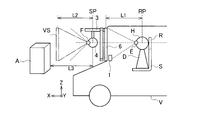
- FIG. 2 is a schematic diagram illustrating the indirect view presentation device according to the first embodiment of the present invention.
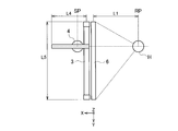
- FIG. 3 is a schematic diagram illustrating a manipulator provided in the indirect view presentation device according to the first embodiment of the present invention.
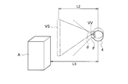
- FIG. 4 is a schematic diagram for explaining the operation of the image drawing unit included in the indirect field presentation device according to the first embodiment of the present invention.
- FIG. 5 is an example illustrating a screen displayed on a stereo display included in the indirect field presentation device according to the first embodiment of the present invention.
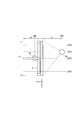
- FIG. 6 is a schematic diagram for explaining the operation of the indirect view presentation device according to the modification of the first embodiment of the present invention.
- FIG. 1 is a block diagram illustrating a basic configuration of an indirect field presentation device according to the first embodiment of the present invention.
- FIG. 2 is a schematic diagram illustrating the indirect view presentation device according to the first embodiment of the present invention.
- FIG. 7 is a block diagram illustrating a basic configuration of an indirect view presentation device according to the second embodiment of the present invention.
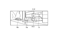
- FIG. 8 is an example illustrating a case where an automobile including the indirect field presentation device according to the second embodiment of the present invention backs up.
- FIG. 9 is a diagram illustrating the inside of an automobile provided with the indirect field presentation device according to the second embodiment of the present invention shown in FIG.
- the indirect field presentation device includes a motion detection unit 1, a motion control unit 2, a manipulator 3, a stereo camera 4, a display control unit 5, and a stereo.
- a display 6, a storage unit 7, a state detection unit 8, and an output unit 9 are provided.
- the indirect field of view presentation apparatus is an apparatus that indirectly presents the field of view of the outside world viewed from the transportation system to a pilot who operates the transportation system such as an automobile, an aircraft, and a ship.
- the motion detection unit 1 is a motion sensor that detects a motion indicating the position and orientation of the head H of the operator D of the vehicle D, which is a transportation facility, at each time.
- the movement of the head H detected by the movement detector 1 may be at least one of the position and orientation of the head H in the system where the operator D exists.
- the motion detector 1 sequentially outputs motion information indicating the detected motion of the head H to the motion controller 2 at a predetermined sampling frequency.
- the motion detection unit 1 may detect the motion of the head H by performing image processing on an image obtained by an image sensor that detects an electromagnetic wave emitted from the head H, for example. In addition, the motion detection unit 1 may detect the motion of the head H using an acceleration sensor, an angular velocity sensor, or the like built in a wearing tool attached to the head H.
- the motion control unit 2 controls the driving of the manipulator 3 that holds the stereo camera 4 so that the stereo camera 4 moves in conjunction with the motion of the head H detected by the motion detection unit 1.
- the motion control unit 2 includes a computer such as a microcontroller.
- the motion control unit 2 generates a command value that commands the manipulator 3 to drive based on the motion information input from the motion detection unit 1, and outputs the command value to the manipulator 3.
- the command value output by the motion control unit 2 indicates at least one of the position and orientation of the stereo camera 4 with respect to the automobile V.
- the manipulator 3 holds the stereo camera 4 and moves the stereo camera 4 in accordance with the movement of the head H detected by the movement detected by the movement detection unit 1 according to the control of the movement control unit 2.
- This is a drive mechanism (robot arm).
- the manipulator 3 is driven based on the command value input from the motion control unit 2 and moves the stereo camera 4.
- the manipulator 3 has six degrees of freedom so that the position and orientation of the stereo camera 4 with respect to the automobile V can be controlled.
- the manipulator 3 drives, for example, three linear motion joints along the XYZ triaxial directions in the three-dimensional orthogonal coordinate system, three rotational joints having the three axial directions as rotational axes, and the linear motion joints and the rotational joints.
- An actuator Various other combinations can be adopted for the joint and actuator of the manipulator 3.
- the rotary joint may be a ball joint.
- the manipulator 3 moves the stereo camera 4 in at least one of the XYZ axes so as to be interlocked with the position of the head H detected by the motion detection unit 1 according to the control of the motion control unit 2. You may make it make it.
- the manipulator 3 uses at least one of the XYZ axes as a rotation axis so as to be interlocked with the direction of the head H detected by the motion detection unit 1 according to the control of the motion control unit 2.
- the stereo camera 4 may be rotated.
- the manipulator 3 is arranged in the stereo camera 4 in at least one of the XYZ axes so as to be interlocked with the direction of the head H detected by the motion detection unit 1 according to the control of the motion control unit 2. May be moved.
- the manipulator 3 may be provided with only a linear joint when the stereo camera 4 is only moved in parallel, and may be provided with only a rotary joint when the stereo camera 4 is rotated only.
- the initial position SP of the stereo camera 4 is set by the motion control unit 2.
- the motion control unit 2 sets the reference position RP of the head H detected by the motion detection unit 1 in a state where the pilot D is sitting on the seat S.
- the motion control unit 2 sets an initial position SP of the stereo camera 4 corresponding to the reference position RP for the manipulator 3.
- the movement of the head H from the reference position RP is linked to the movement of the stereo camera 4 from the initial position SP.
- the motion control unit 2 sets the position of the head H in a state where it hits the headrest R of the seat S on which the operator D sits as a reference position RP.
- the head H is rarely located behind the headrest R.
- the motion control unit 2 sets the initial position SP of the stereo camera 4 as the last end in the movable range in the front-rear direction of the automobile V.
- the stereo camera 4 can move out of the movable range by setting the initial position SP as the last end. Operation is reduced and the range of motion can be used effectively.
- the motion control unit 2 may set the position of the head H most frequently detected by the motion detection unit 1 as the reference position RP.
- the manipulator 3 can effectively use the movable range by setting the initial position SP of the stereo camera 4 based on the reference position RP of the head H that exists for the longest time.
- the motion control unit 2 may set the center in the movable range of each drive shaft of the manipulator 3 as the reference position RP.
- the movable range of the manipulator 3 is determined so as to correspond to the movable range of the head H.
- the manipulator 3 has a drive shaft having the same movable range as the movable range of the head H, it is not necessary to set the initial position SP for the drive shaft having a movable range equal to or larger than the movable range of the head H.
- the manipulator 3 has a drive axis (Y axis) with a movable range L5 that is greater than or equal to the movable range of the head H, and therefore it is not necessary to set the initial position SP for the Y axis.
- the manipulator 3 detects a motion indicating the position and orientation of the stereo camera 4 at each time, and outputs it to the display control unit 5 as motion information indicating the motion of the stereo camera 4.
- the stereo camera 4 is mounted on the car V.
- the stereo camera 4 captures a stereoscopic image in the traveling direction (front) of the automobile V.
- the stereo camera 4 is held by the manipulator 3.
- the stereo camera 4 moves in conjunction with the movement of the head H detected by the movement detection unit 1 when the manipulator 3 is driven.
- the stereo camera 4 sequentially outputs the captured stereoscopic image to the display control unit 5 at a predetermined frequency.
- the display control unit 5 includes a difference detection unit 51, an image drawing unit 52, a CG generation unit 53, and a warning unit 54.
- the display control unit 5 includes a computer such as a microcontroller.
- the difference detection unit 51, the image drawing unit 52, the CG generation unit 53, and the warning unit 54 in FIG. 1 are each displayed as a logical structure, and may be configured by separate hardware or integrated hardware. May be.
- the display control unit 5 performs image processing on a stereoscopic image taken by the stereo camera 4 at a predetermined frequency, and sequentially displays it on the stereo display 6.
- the actual movement of the head H, the movement information of the movement detection unit 1, the command value of the movement control unit 2, the movement information of the manipulator 3, and the display of the stereo display 6 are between the corresponding generation times.
- a delay of approximately ms order occurs.
- the display control unit 5 performs image processing on the image displayed on the stereo display 6 so as to compensate for at least part of the delay time that occurs between the actual movement of the head H and the display on the stereo display 6. .
- the time lag between the movement information of the movement detector 1 and the movement of the manipulator 3 is larger than the others.
- the difference detection unit 51 inputs the movement information of the movement detection unit 1 and the movement information of the manipulator 3, and detects the difference between the movement of the head H detected by the movement detection unit 1 and the movement of the stereo camera 4. To do. As illustrated in FIG. 4, the difference detection unit 51 calculates a virtual viewpoint VV based on the movement of the head H detected by the movement detection unit 1.
- the virtual viewpoint VV is a viewpoint of the stereo camera 4 virtualized so as to correspond to the movement of the head H in order to compensate for the delay of the movement of the stereo camera 4 with respect to the movement of the head H detected by the movement detector 1.
- the difference detection unit 51 detects the difference between the virtual viewpoint VV and the viewpoint F of the stereo camera 4 obtained from the movement information of the manipulator 3 as the difference between the movement of the head H and the movement of the stereo camera 4.
- the difference detection unit 51 may calculate the virtual viewpoint VV based on the command value of the motion control unit 2.
- the image drawing unit 52 inputs a stereoscopic image taken by the stereo camera 4, corrects distortion or the like in the stereoscopic image, and performs mapping so as to correspond to the virtual screen VS.
- the distance between the head H and the stereo display 6 at the reference position RP is L1.
- the virtual screen VS is, for example, a screen that has the same size and the same shape as the stereo display 6 and is virtually located at the same distance L2 as the distance L1 from the initial position SP of the stereo camera 4.
- the image mapped to the virtual screen VS becomes a view seen from the viewpoint F of the stereo camera 4 using the virtual screen VS as a window, like a view seen from the viewpoint E of the operator D using the stereo display 6 as a window.
- the object A located at a distance L3 from the stereo camera 4 is displayed on the stereo display 6 so as to be seen at a distance L3 from the operator D.
- the image drawing unit 52 Based on the difference detected by the difference detection unit 51, the image drawing unit 52 performs image processing on the stereoscopic image captured by the stereo camera 4 using affine transformation, thereby generating the virtual screen VS from the virtual viewpoint VV. Draw the viewed image. As illustrated in FIG. 4, the image drawing unit 52 draws a virtual image when the virtual screen VS is viewed from the virtual viewpoint VV when the virtual screen VS is included inside the viewing angle ⁇ of the stereo camera 4. be able to.
- the image drawing unit 52 changes the stereoscopic image captured by the stereo camera 4 based on the difference detected by the difference detection unit 51 to the left and right. Shift in direction.
- the image drawing unit 52 displays a stereoscopic image captured by the stereo camera 4 based on the difference detected by the difference detection unit 51. Shift up and down.
- the image drawing unit 52 enlarges or reduces (zooms in) the stereoscopic image captured by the stereo camera 4 based on the difference detected by the difference detection unit 51. ⁇ Out)
- the image drawing unit 52 rotates the two captured images together with the virtual screen VS so as to always remain horizontal.
- the image drawing unit 52 determines whether the stereo image captured by the stereo camera 4 is based on the difference detected by the difference detection unit 51. The two images are alternately shifted up and down.
- the image drawing unit 52 is a stereoscopic image captured by the stereo camera 4 based on the difference detected by the difference detection unit 51. Zoom in and out alternately on the left and right two images.
- the image drawing unit 52 converts the stereoscopic image captured by the stereo camera 4 in the vertical direction based on the difference detected by the difference detection unit 51. Shift and zoom in / out.
- the image drawing unit 52 performs image processing on the stereoscopic image captured by the stereo camera 4 using affine transformation, and draws a virtual image viewed from the virtual viewpoint VV, thereby obtaining a difference.
- the difference delay time detected by the detection unit 51 is compensated. Accordingly, the image drawing unit 52 can efficiently compensate for the delay time from the actual movement of the head H to the display on the stereo display 6.
- the image drawing unit 52 may draw a virtual image viewed from the virtual viewpoint VV only when the difference detected by the difference detection unit 51 is equal to or greater than a predetermined threshold.
- the CG generation unit 53 generates a CG to be combined with the image drawn by the image drawing unit 52 based on the information stored in the storage unit 7 and the state of the automobile V detected by the state detection unit 8.
- the storage unit 7 stores map information, feature information corresponding to the map information, and the like.
- the state detection unit 8 detects the traveling state of the automobile V based on detection results of a positioning system, an acceleration sensor, an angular velocity sensor, a rudder angle sensor, a vehicle speed sensor, and the like. That is, the state detection unit 8 detects the current position, speed, posture with respect to the travel route, etc. of the vehicle V in the map information as the travel state of the vehicle V.
- the state detection unit 8 may include a distance measuring sensor that detects an obstacle or the like existing around the automobile V.
- the CG generation unit 53 generates a CG image corresponding to the stereoscopic video captured by the stereo camera 4.
- the CG generation unit 53 generates a CG image of a feature that may exist at the angle of view of the stereo camera 4 from the current position detected by the state detection unit 8. For example, as shown in FIG. 5, the CG generation unit 53 may generate a CG image of the feature B that is originally shielded by an obstacle and is not captured by the stereo camera 4.
- the CG generation unit 53 may generate a CG image that highlights the feature C such as an intersection by texture mapping.
- the CG generation unit 53 may generate a CG image indicating an icon indicating a type of a feature or a destination, a travel route, and the like.
- the image drawing unit 52 synthesizes the CG image generated by the CG generation unit 53 and the image processed based on the difference detected by the difference detection unit 51 so as to correspond to each other, for example, as shown in FIG. In this way, it is displayed on the stereo display 6.
- the warning unit 54 inputs the movement information of the movement detection unit 1 and the movement information of the manipulator 3, and the movement of the stereo camera 4 is not interlocked with the movement of the head H detected by the movement detection unit 1. Is detected.
- the warning unit 54 warns the operator D via the output unit 9 when the movement of the stereo camera 4 is not linked with the movement of the head H detected by the movement detection unit 1.
- the warning unit 54 is, for example, when the movement of the head H is out of the detectable range of the movement detection unit 1, when a command value out of the movable range is input to the manipulator 3, or when a failure of the device is detected, etc. In addition, it may be determined that the stereo camera 4 is not linked to the head H.
- the output unit 9 warns the operator D according to the control of the warning unit 54.
- the output unit 9 includes, for example, a display device that displays light, images, characters, and the like, and an acoustic device such as a speaker that outputs sound.
- the output unit 9 may be configured as a part of the stereo display 6.
- the stereo display 6 is a display device that displays a stereoscopic image captured by the stereo camera 4 to the operator D.
- the stereo display 6 may be a glasses type using a liquid crystal shutter or a polarizing filter, or may be a naked eye type using a parallax barrier or a lenticular lens.
- the stereo display 6 may be a head mounted display (HMD).
- HMD head mounted display
- the virtual screen VS does not correspond to the HMD and is set to have a predetermined shape at a predetermined distance from the stereo camera 4, and the display control unit 5 separately performs processing related to head tracking. I do.
- the motion detection unit 1 may detect a target mounted on a mounting tool (glasses) mounted on the head H. Or you may make it the motion detection part 1 detect the motion of the head H by the acceleration sensor, the angular velocity sensor, etc. which were mounted in the mounting tool.
- the stereo display 6 is a naked eye type, the binocular parallax barrier is optimized based on the distance from the head H when the operator D is sitting on the seat S.
- the stereoscopic image captured by the stereo camera 4 that follows the head H of the operator D is displayed on the stereo display 6, thereby responding to the motion of the operator D.
- Motion parallax can be expressed.
- the movement of the stereo camera 4 does not need to completely follow the movement of the head H, and the manufacturing cost can be reduced by restricting the drive shaft of the manipulator 3, and the movement control unit 2 and display
- the processing speed of the control unit 5 can be improved.
- the stereo display 6 displays an image photographed by the stereo camera 4 that has been subjected to image processing based on the difference detected by the difference detection unit 51. Therefore, the indirect view presentation device according to the first embodiment can compensate for at least a part of the delay time from the motion detected by the motion detection unit 1 to the display on the stereo display 6. In particular, when the difference detection unit 51 detects the difference between the movement of the head H detected by the movement detection unit 1 and the movement of the stereo camera 4, the stereo display 6 displays an image that efficiently compensates for the delay time. can do.
- the range of motion of the manipulator 3 is set. It can be used effectively.
- the warning unit 54 warns the driver D that the stereo camera 4 is not interlocked with the movement of the head H. Therefore, the warning unit 54 can warn that a failure occurs in the space recognition of the pilot D, and can improve safety.
- the initial position SP of the stereo camera 4 may be set for each operation mode.
- the manipulator 3 for example, as shown in FIG. 6, a plurality of initial positions SP1 to SP4 are set by the motion control unit 2.
- the initial position SP1 coincides with the reference position RP in the left-right direction (Y-axis direction) of the automobile V.
- the initial position SP2 is located at the center in the left-right direction of the automobile V.
- the initial position SP2 is located at the center in the left-right direction of the automobile V.
- the initial positions SP3 and SP4 are located on either side in the left-right direction of the automobile V.
- the manipulator 3 moves the stereo camera 4 from the initial position SP corresponding to the operation mode to a position away from the initial position SP corresponding to the operation mode in response to the switching of the operation mode.
- the operation mode may be switched according to an operation by the operator D, for example, or may be automatically switched according to the traveling state of the automobile V detected by the state detection unit 8.
- the operation mode may be switched to the right-side initial position SP4 when an obstacle is detected in the front right of the vehicle V.
- the pilot D can be provided with a field of view that is very close to the field of view that would be visible in the front.
- the driver D can improve driving operability by obtaining the sense of distance on the left and right symmetrically.
- the operator D can easily determine the initial positions SP3 and SP4 side such as narrow roads and obstacles.
- the indirect visual field presentation apparatus includes a plurality of manipulators 3-1, 3-2, ..., 3-n and a plurality of stereo cameras 4-1, 4-2. ,..., 4-n are different from the first embodiment.
- Other configurations, operations, and effects that are not described in the second embodiment are substantially the same as those in the first embodiment and are omitted because they overlap.
- the plurality of manipulators 3-1 to 3-n are installed at different locations of the vehicle V, respectively.
- the plurality of stereo cameras 4-1 to 4-n are held by the plurality of manipulators 3-1 to 3-n corresponding to the plurality of manipulators 3-1 to 3-n.
- the manipulator 3-1 and the stereo camera 4-1 correspond to the manipulator 3 and the stereo camera 4 in the first embodiment, respectively.
- the display control unit 5 inputs an image photographed by the stereo cameras 4-1 to 4-n according to the operation mode and displays the image on the stereo display 6.
- the motion control unit 2 drives the manipulators 3-1 to 3-n corresponding to the stereo cameras 4-1 to 4-n corresponding to the operation mode so as to be linked to the motion detected by the motion detection unit 1. To do.
- the indirect view presentation device includes a manipulator 3-2 and a stereo camera 4-2 positioned behind the automobile V.
- the stereo camera 4-2 photographs the back of the automobile V.
- the motion control unit 2 controls the manipulator 3-2 so that the stereo camera 4-2 moves partially different from the stereo camera 4-1, which captures the front.
- the image drawing unit 52 causes the stereo display 6 to display the image captured by the stereo camera 4-2 by reversing the image horizontally.
- the manipulator 3-2 moves the stereo camera 4 to the front of the vehicle V according to the control of the motion control unit 2. Move to the right. That is, the stereo camera 4 moves to the left with respect to the shooting direction (in front of the stereo camera 4-2). Further, when the head H rotates counterclockwise (rotation in one direction around the Z axis), the manipulator 3-2 rotates clockwise (Z axis) according to the control of the motion control unit 2. Rotate around in the other direction).
- the manipulator 3-2 responds to the movement of the head H in the left-right direction (movement in the Y-axis direction and rotation around the Z-axis).
- the stereo camera 4-2 is moved so as to be reversed.
- the vertical direction is the same as that of the manipulator 3-1 and the stereo camera 4-1.
- the indirect view presentation device includes a switching unit 10 that switches to any one of a plurality of operation modes.
- the switching unit 10 can be configured by, for example, a touch sensor that detects an operation by the operator D.
- the switching unit 10 may be formed integrally with a display device such as the stereo display 6 as a touch panel.
- the switching unit 10 switches to one of a plurality of operation modes according to the operation by the operator D.
- the switching unit 10 may automatically switch the operation mode according to the traveling state of the automobile V detected by the state detection unit 8.
- the switching unit 10 corresponds to the stereo camera 4-2 from the operation mode corresponding to the stereo camera 4-1 when the state detection unit 8 detects a gear change from the drive of the automobile V to the reverse. Switch to the operation mode you want to use.
- the motion control unit 2 starts driving the manipulator 3-2, and the display control unit 5 causes the stereo display 6 to display an image photographed by the stereo camera 4-2.
- the automobile V is parked in a parking lot. On the left side of the automobile V, other automobiles Va and Vb are parked. In this state, when the operator D turns the vehicle V back while turning the steering wheel to the left, the vehicle V backs leftward with respect to the front, that is, rightward with respect to the rear. At this time, the image displayed on the stereo display 6 is reversed in the left-right direction with respect to the image taken by the stereo camera 4 as shown in FIG.
- the stereo display 6 may display the CG image of the arrow G indicating the traveling direction as shown in FIG. 9 generated by the CG generation unit 53.
- the CG generation unit 53 may generate a CG image of the arrow G based on the steering angle detected by the state detection unit 8.
- the image drawing unit 52 displays an image captured by the stereo camera 4-2 on the two stereo displays 6.
- the two stereo displays 6 are arranged so as to be adjacent to each other so as to connect the images and to face the head H of the operator D.
- the stereo display 6 can provide a natural view to the operator D even when the shooting direction of the stereo cameras 4-1 to 4-n is changed.
- the stereo display 6 may be a combination of three or more and may be a curved display.
- the stereo camera 4 may be a single camera that captures a planar image.
- the stereo display 6 may be a display device that displays a planar image. Even in this case, by controlling the camera to follow the motion of the head H, motion parallax according to the motion of the operator D can be expressed on the display device.
- the operator D does not necessarily have to get on the automobile V (transportation vehicle). That is, if at least the stereo camera 4 and the manipulator 3 are mounted on the transportation facility, the indirect view presentation device represents motion parallax according to the motion of the pilot D in the remote control of the transportation facility by the pilot D. Can do.
- the stereo display 6 corresponding to the entire area of the windshield of the automobile V is illustrated in FIG. 2, but various dimensions can be adopted for the stereo display 6.
- the stereo display 6 may be a display of a navigation device or a display installed so as to correspond to the lower part of the windshield.
- the height of the viewpoint E of the pilot D corresponds to the height of the viewpoint F of the stereo camera 4 is illustrated in FIG. 2, the heights of the viewpoint E and the viewpoint F need not necessarily match. Absent.
- the warning unit 54 when the warning unit 54 detects the movement of the head H such that the stereoscopic display 6 cannot be stereoscopically viewed, the warning unit 54 sends the driver via the output unit 9. D may be warned.
- the warning unit 54 for example, against the movement of the head H in which the interpupillary distance in the horizontal direction deviates from the design of the stereo display 6 or the tilt of the head H during roll rotation exceeds the allowable error of the polarization filter. It is determined that the stereoscopic display 6 cannot be stereoscopically viewed.
- the image pickup device included in the stereo camera 4 may be configured to always keep horizontal. Thereby, the image processing for keeping the image horizontal in the image drawing unit 52 can be omitted, and the processing load on the image drawing unit 52 can be reduced. Therefore, the delay time from the movement of the head H to the display on the stereo display 6 can be reduced.
- the motion control unit 2 generates a command value for the manipulator 3 based on the motion of the head H predicted based on the motion information of the motion detection unit 1. You may do it. That is, the motion control unit 2 predicts the motion that the head H will perform based on the momentary change of motion information, and controls the manipulator 3 so that the stereo camera 4 moves in response to the prediction. To do.
- the stereo cameras 4-1 to 4-n and the manipulators 3-1 to 3-n may be installed on the side of the automobile V such as a door mirror, on the roof, or the like.
- the display control unit 5 may synthesize images captured by a plurality of stereo cameras 4 held by one manipulator 3 and display them on the stereo display 6 with the angle of view increased.
- the present invention includes various embodiments that are not described here, such as configurations in which the configurations described in the first and second embodiments are mutually applied. Therefore, the technical scope of the present invention is defined only by the invention specifying matters according to the scope of claims reasonable from the above description.
- an indirect visual field presentation device capable of expressing motion parallax according to the motion of the pilot by the camera being interlocked with the motion of the head of the pilot.
- V Car Transportation
- 3 manipulator 4 stereo camera (camera) 6 Stereo display (display device)
Landscapes
- Engineering & Computer Science (AREA)
- Multimedia (AREA)
- Mechanical Engineering (AREA)
- Signal Processing (AREA)
- Aviation & Aerospace Engineering (AREA)
- Manipulator (AREA)
- Testing, Inspecting, Measuring Of Stereoscopic Televisions And Televisions (AREA)
Abstract
間接視界提示装置は、自動車Vに搭載されたステレオカメラ4と、自動車Vの操縦者Dの頭部Hの運動を検出する運動検出部1と、運動検出部1により検出された頭部Hの運動に連動するように、ステレオカメラ4を運動させるマニピュレータ3と、ステレオカメラ4により撮影された画像を操縦者Dに表示するステレオディスプレイ6とを備える。
Description
本発明は、操縦者に対して間接的に視界を提示する間接視界提示装置に関する。
航空機等の輸送機関において乗員に視界を提示する装置として、ステレオカメラにより撮像された画像から生成された立体視界情報及び障害物情報を含む融合視界情報を可視像として乗員に表示する装置が提案されている(特許文献1参照)。
しかしながら、特許文献1に記載の装置は、固定のステレオカメラにより撮像された映像を表示するため、両眼視差を表現できるが、操縦者の頭部の運動に応じた運動視差を表現できず、操縦者の立体空間の認識に破綻を生じる可能性がある。
本発明は、上記問題点を鑑み、操縦者の運動に応じた運動視差を表現可能な間接視界提示装置を提供することを目的とする。
本発明の一態様に係る間接視界提示装置は、輸送機関に搭載されたカメラと、運動検出部と、マニピュレータと、表示装置とを備える。運動検出部は、輸送機関の操縦者の頭部の運動を検出する。マニピュレータは、運動検出部により検出された頭部の運動に連動するように、カメラを運動させる。表示装置は、カメラにより撮影された画像を操縦者に表示する。
次に、図面を参照して、本発明の第1及び第2実施形態を説明する。以下の図面の記載において、同一の部分には同一の符号を付し、重複する説明を省略する。
(第1実施形態)
本発明の第1実施形態に係る間接視界提示装置は、図1に示すように、運動検出部1と、運動制御部2と、マニピュレータ3と、ステレオカメラ4と、表示制御部5と、ステレオディスプレイ6と、記憶部7と、状態検出部8と、出力部9を備える。第1実施形態に係る間接視界提示装置は、自動車、航空機、船舶等の輸送機関を操縦する操縦者に対して、輸送機関から見た外界の視界を間接的に提示する装置である。
本発明の第1実施形態に係る間接視界提示装置は、図1に示すように、運動検出部1と、運動制御部2と、マニピュレータ3と、ステレオカメラ4と、表示制御部5と、ステレオディスプレイ6と、記憶部7と、状態検出部8と、出力部9を備える。第1実施形態に係る間接視界提示装置は、自動車、航空機、船舶等の輸送機関を操縦する操縦者に対して、輸送機関から見た外界の視界を間接的に提示する装置である。
運動検出部1は、例えば図2に示すように、輸送機関である自動車Vの操縦者Dの頭部Hの、各時間における位置及び向きを示す運動を検出するモーションセンサである。運動検出部1が検出する頭部Hの運動は、操縦者Dが存在する系における頭部Hの位置及び向きの少なくともいずれかであってもよい。運動検出部1は、検出した頭部Hの運動を示す運動情報を所定のサンプリング周波数で運動制御部2に逐次出力する。
運動検出部1は、例えば、頭部Hから出射される電磁波を検出するイメージセンサにより得られる画像に対して画像処理することにより頭部Hの運動を検出してもよい。また、運動検出部1は、頭部Hに装着される装着具に内蔵された加速度センサ及び角速度センサ等により頭部Hの運動を検出してもよい。
運動制御部2は、運動検出部1により検出された頭部Hの運動に連動してステレオカメラ4が運動するように、ステレオカメラ4を保持するマニピュレータ3の駆動を制御する。運動制御部2は、マイクロコントローラ等のコンピュータから構成される。運動制御部2は、運動検出部1から入力した運動情報に基づいて、マニピュレータ3に駆動を指令する指令値を生成し、マニピュレータ3に出力する。運動制御部2が出力する指令値は、自動車Vに対するステレオカメラ4の位置及び向きの少なくともいずれかを示す。
マニピュレータ3は、ステレオカメラ4を保持し、運動制御部2の制御に応じて、運動検出部1により検出された運動に検出された頭部Hの運動に連動するように、ステレオカメラ4を運動させる駆動機構(ロボットアーム)である。マニピュレータ3は、運動制御部2から入力した指令値に基づいて駆動し、ステレオカメラ4を運動させる。マニピュレータ3は、自動車Vに対するステレオカメラ4の位置及び向きを制御可能なように6自由度を有する。
マニピュレータ3は、例えば、3次元直交座標系におけるXYZの3軸方向に沿う3つの直動関節と、3軸方向を回転軸とする3つの回転関節と、直動関節及び回転関節をそれぞれ駆動するアクチュエータとを備える。マニピュレータ3の関節及びアクチュエータは、他の種々の組み合わせが採用可能である。例えば回転関節は、ボールジョイントであってもよい。
マニピュレータ3は、運動制御部2の制御に応じて、運動検出部1により検出された頭部Hの位置に連動するように、XYZ軸のうち少なくともいずれか1軸方向に、ステレオカメラ4を移動させるようにしてもよい。また、マニピュレータ3は、運動制御部2の制御に応じて、運動検出部1により検出された頭部Hの向きに連動するように、XYZ軸のうち少なくともいずれか1軸方向を回転軸として、ステレオカメラ4を回転させるようにしてもよい。
或いは、マニピュレータ3は、運動制御部2の制御に応じて、運動検出部1により検出された頭部Hの向きに連動するように、XYZ軸のうち少なくともいずれか1軸方向に、ステレオカメラ4を移動させるようにしてもよい。マニピュレータ3は、ステレオカメラ4に平行移動のみをさせる場合、直動関節のみを備えればよく、ステレオカメラ4に回転のみをさせる場合、回転関節のみを備えればよい。
マニピュレータ3は、運動制御部2により、ステレオカメラ4の初期位置SPが設定される。運動制御部2は、操縦者Dが座席Sに座った状態において運動検出部1により検出された頭部Hの基準位置RPを設定する。運動制御部2は、マニピュレータ3に対して、基準位置RPに応じたステレオカメラ4の初期位置SPを設定する。基準位置RPからの頭部Hの運動は、初期位置SPからのステレオカメラ4の運動に連動する。
運動制御部2は、例えば、図2に示すように、操縦者Dが座る座席SのヘッドレストRに当たった状態の頭部Hの位置を基準位置RPとして設定する。頭部Hは、ヘッドレストRより後方に位置することが少ない。このため、マニピュレータ3は、運動制御部2により、ステレオカメラ4の初期位置SPを自動車Vの前後方向の可動域における最後端として設定される。例えば、図3に示すように、マニピュレータ3が、前後方向(X軸方向)における可動域L4を有する場合、ステレオカメラ4は、初期位置SPを最後端とすることにより、可動域を外れるような動作をすることが低減され、可動域を有効に活用できる。
運動制御部2は、運動検出部1により最も多く検出された頭部Hの位置を、基準位置RPとして設定するようにしてもよい。マニピュレータ3は、最も長時間存在する頭部Hの基準位置RPに基づいてステレオカメラ4の初期位置SPが設定されることにより、可動域を有効に活用することができる。或いは、運動制御部2は、マニピュレータ3の各駆動軸の可動域における中心を基準位置RPとして設定するようにしてもよい。
マニピュレータ3は、頭部Hの可動域に対応するように可動域が決定されている。マニピュレータ3は、頭部Hの可動域と同じ可動域の駆動軸を有する場合、頭部Hの可動域以上の可動域を有する駆動軸について初期位置SPの設定は不要である。例えば、図3に示すように、マニピュレータ3は、頭部Hの可動域以上の可動域L5の駆動軸(Y軸)を有するため、Y軸について初期位置SPを設定される必要がない。
マニピュレータ3は、ステレオカメラ4の各時間における位置及び向きを示す運動を検出し、ステレオカメラ4の運動を示す運動情報として表示制御部5に出力する。
ステレオカメラ4は、自動車Vに搭載される。ステレオカメラ4は、例えば、自動車Vの進行方向(前方)の立体画像を撮影する。ステレオカメラ4は、マニピュレータ3に保持される。ステレオカメラ4は、マニピュレータ3が駆動することにより、運動検出部1により検出された頭部Hの運動に連動するように運動する。ステレオカメラ4は、撮影した立体画像を所定の周波数で表示制御部5に逐次出力する。
表示制御部5は、差分検出部51と、画像描画部52と、CG生成部53と、警告部54とを有する。表示制御部5は、マイクロコントローラ等のコンピュータから構成される。図1における差分検出部51、画像描画部52、CG生成部53及び警告部54は、それぞれ論理構造としての表示であり、それぞれ別個のハードウェアから構成されてもよく、一体のハードウェアから構成されてもよい。表示制御部5は、ステレオカメラ4により撮影された立体画像を所定の周波数で画像処理し、ステレオディスプレイ6に逐次表示させる。
実際の頭部Hの運動と、運動検出部1の運動情報と、運動制御部2の指令値と、マニピュレータ3の運動情報と、ステレオディスプレイ6の表示とは、互いに対応する発生時刻それぞれの間に概ねmsオーダーの遅延が生じる。表示制御部5は、実際の頭部Hの運動からステレオディスプレイ6の表示までの間に生じる遅延時間の少なくとも一部を補償するように、ステレオディスプレイ6に表示させる画像に対して画像処理を施す。実際の頭部Hの運動からステレオディスプレイ6の表示までの間において、運動検出部1の運動情報とマニピュレータ3の運動との間のタイムラグは他に比べて大きい。
差分検出部51は、運動検出部1の運動情報と、マニピュレータ3の運動情報とを入力し、運動検出部1により検出された頭部Hの運動と、ステレオカメラ4の運動との差分を検出する。差分検出部51は、図4に示すように、運動検出部1により検出された頭部Hの運動に基づいて、仮想視点VVを算出する。仮想視点VVは、運動検出部1により検出された頭部Hの運動に対するステレオカメラ4の運動の遅延を補償するために、頭部Hの運動に対応するように仮想されたステレオカメラ4の視点Fである。
差分検出部51は、仮想視点VVと、マニピュレータ3の運動情報から得られるステレオカメラ4の視点Fとの差分を、頭部Hの運動と、ステレオカメラ4の運動との差分として検出する。差分検出部51は、運動制御部2の指令値に基づいて、仮想視点VVを算出するようにしてもよい。
画像描画部52は、ステレオカメラ4により撮影された立体画像を入力し、立体画像における歪曲等を補正し、仮想スクリーンVSに対応するようにマッピングする。ここで、図2に示すように、基準位置RPにおける頭部Hとステレオディスプレイ6との間の距離をL1とする。仮想スクリーンVSは、例えば、ステレオディスプレイ6と同一寸法及び同一形状を有し、ステレオカメラ4の初期位置SPから、距離L1と同一の距離L2に位置するように仮想されるスクリーンである。
これにより、仮想スクリーンVSにマッピングされた画像は、ステレオディスプレイ6を窓として操縦者Dの視点Eから見た展望のように、仮想スクリーンVSを窓としてステレオカメラ4の視点Fから見た展望に対応する。よって、図2及び図4に示すように、ステレオカメラ4から距離L3の位置にある物体Aは、操縦者Dから距離L3の位置に見えるように、ステレオディスプレイ6に表示される。
画像描画部52は、差分検出部51により検出された差分に基づいて、ステレオカメラ4により撮影された立体画像に対してアフィン変換を用いて画像処理することにより、仮想視点VVから仮想スクリーンVSを見た画像を描画する。画像描画部52は、図4に示すように、仮想スクリーンVSがステレオカメラ4の視野角θの内側に含まれる場合、仮想視点VVから仮想スクリーンVSを見たときの仮想的な画像を描画することができる。
例えば、画像描画部52は、ステレオカメラ4が左右方向(Y軸方向)に遅延を生じた場合、差分検出部51により検出された差分に基づいて、ステレオカメラ4により撮影された立体画像を左右方向にシフトさせる。同様に、画像描画部52は、ステレオカメラ4が上下方向(Z軸方向)に遅延を生じた場合、差分検出部51により検出された差分に基づいて、ステレオカメラ4により撮影された立体画像を上下方向にシフトさせる。或いは、画像描画部52は、前後方向(X軸方向)に遅延を生じた場合、差分検出部51により検出された差分に基づいて、ステレオカメラ4により撮影された立体画像を拡大又は縮小(ズームイン・アウト)させる。
画像描画部52は、ステレオカメラ4の両眼に対応する2つのカメラが、ロール回転により水平方向から外れる場合、撮影された2枚の画像を、それぞれ仮想スクリーンVSと共に常に水平を保つように回転させる。画像描画部52は、ステレオカメラ4がロール回転(X軸回りの回転)に遅延を生じた場合、差分検出部51により検出された差分に基づいて、ステレオカメラ4により撮影された立体画像における左右2枚の画像を互い違いに上下方向にシフトさせる。
また、画像描画部52は、ステレオカメラ4がヨー回転(Z軸回りの回転)に遅延を生じた場合、差分検出部51により検出された差分に基づいて、ステレオカメラ4により撮影された立体画像における左右2枚の画像を互い違いにズームイン・アウトさせる。或いは、画像描画部52は、ピッチ回転(Y軸回りの回転)に遅延を生じた場合、差分検出部51により検出された差分に基づいて、ステレオカメラ4により撮影された立体画像を上下方向のシフト及びズームイン・アウトさせる。
以上のように、画像描画部52は、ステレオカメラ4により撮影された立体画像に対してアフィン変換を用いて画像処理して、仮想視点VVから見た仮想的な画像を描画することにより、差分検出部51により検出された差分の遅延時間を補償する。これにより、画像描画部52は、実際の頭部Hの運動からステレオディスプレイ6の表示までの間の遅延時間を効率良く補償することができる。なお、画像描画部52は、差分検出部51により検出された差分が所定の閾値以上となった場合のみ、仮想視点VVから見た仮想的な画像を描画するようにしてもよい。
CG生成部53は、記憶部7が記憶する情報及び状態検出部8が検出する自動車Vの状態に基づいて、画像描画部52により描画された画像と合成するCGを生成する。記憶部7は、地図情報、及び地図情報に対応する地物情報等を記憶する。状態検出部8は、測位システム、加速度センサ、角速度センサ、舵角センサ、車速センサ等の検出結果に基づいて、自動車Vの走行状態を検出する。すなわち、状態検出部8は、自動車Vの走行状態として、地図情報における自動車Vの現在位置、速度、走行経路に対する姿勢等を検出する。その他、状態検出部8は、自動車Vの周辺に存在する障害物等を検出する測距センサ等を有するようにしてもよい。
CG生成部53は、ステレオカメラ4により撮影された立体映像に対応するCG画像を生成する。CG生成部53は、状態検出部8により検出された現在位置からのステレオカメラ4の画角に存在し得る地物のCG画像を生成する。CG生成部53は、例えば、図5に示すように、本来障害物により遮蔽されてステレオカメラ4により撮影されない地物BのCG画像を生成するようにしてもよい。また、CG生成部53は、例えば交差点等の地物Cをテクスチャマッピングにより強調表示するCG画像を生成するようにしてもよい。その他、CG生成部53は、地物の種類や目的地を示すアイコン、走行経路等を示すCG画像を生成するようにしてもよい。
画像描画部52は、CG生成部53により生成されたCG画像と、差分検出部51により検出された差分に基づいて画像処理された画像とを互いに対応するように合成し、例えば図5に示すように、ステレオディスプレイ6に表示させる。
警告部54は、運動検出部1の運動情報と、マニピュレータ3の運動情報とを入力し、ステレオカメラ4の運動が、運動検出部1により検出された頭部Hの運動と連動していないことを検出する。警告部54は、ステレオカメラ4の運動が、運動検出部1により検出された頭部Hの運動と連動していない場合、出力部9を介して操縦者Dに警告する。警告部54は、例えば、頭部Hの運動が運動検出部1の検出可能範囲から外れた場合、マニピュレータ3に可動域を外れる指令値が入力された場合、装置の故障が検出された場合等に、ステレオカメラ4が頭部Hに連動していないと判断すればよい。
出力部9は、警告部54の制御に応じて、操縦者Dに警告する。出力部9は、例えば、光、画像、文字等を表示する表示装置や、音声を出力するスピーカ等の音響デバイスから構成される。出力部9は、ステレオディスプレイ6の一部として構成されてもよい。
ステレオディスプレイ6は、ステレオカメラ4により撮影された立体画像を操縦者Dに表示する表示装置である。ステレオディスプレイ6は、液晶シャッタや偏光フィルタを用いた眼鏡式であってもよく、視差バリアやレンチキュラーレンズを用いた裸眼式であってもよい。或いは、ステレオディスプレイ6は、ヘッドマウントディスプレイ(HMD)であってもよい。但し、ステレオディスプレイ6がHMDの場合、仮想スクリーンVSは、HMDと対応せず、ステレオカメラ4から所定の距離に所定の形状を有するように設定され、表示制御部5は、別途ヘッドトラッキングに関する処理を行う。
ステレオディスプレイ6が眼鏡式又はHMDの場合、運動検出部1は、頭部Hに装着された装着具(眼鏡)に搭載されたターゲットを検出するようにしてもよい。或いは、運動検出部1は、装着具に搭載された加速度センサ及び角速度センサ等により、頭部Hの運動を検出するようにしてもよい。ステレオディスプレイ6は、裸眼式の場合、操縦者Dが座席Sに座った状態における頭部Hとの距離に基づいて両眼視差障壁が最適化される。
第1実施形態に係る間接視界提示装置によれば、操縦者Dの頭部Hに追従するステレオカメラ4により撮影された立体画像をステレオディスプレイ6に表示することにより、操縦者Dの運動に応じた運動視差を表現することができる。なお、ステレオカメラ4の運動は、頭部Hの運動に完全に追従する必要はなく、マニピュレータ3の駆動軸を制限することにより、製造コストを低減させることができる他、運動制御部2及び表示制御部5の処理速度を向上することができる。
また、第1実施形態に係る間接視界提示装置によれば、ステレオディスプレイ6が、差分検出部51により検出された差分に基づいて画像処理された、ステレオカメラ4により撮影された画像を表示する。よって、第1実施形態に係る間接視界提示装置は、運動検出部1により検出された運動からステレオディスプレイ6の表示までの少なくとも一部の遅延時間を補償することができる。特に、差分検出部51が運動検出部1により検出された頭部Hの運動とステレオカメラ4の運動との差分を検出することにより、ステレオディスプレイ6は、効率良く遅延時間を補償する画像を表示することができる。
また、第1実施形態に係る間接視界提示装置によれば、頭部Hに対して設定された基準位置RPに基づいてステレオカメラ4の初期位置SPを設定することにより、マニピュレータ3の可動域を有効に活用することができる。
また、第1実施形態に係る間接視界提示装置によれば、警告部54は、ステレオカメラ4が頭部Hの運動と連動していないことを操縦者Dに警告する。よって、警告部54は、操縦者Dの空間認識に破綻を生じることを警告することができ、安全性を向上することができる。
―変形例―
第1実施形態に係る間接視界提示装置は、ステレオカメラ4の初期位置SPが、動作モード毎に設定されるようにしてもよい。マニピュレータ3は、例えば、図6に示すように、運動制御部2により、複数の初期位置SP1~SP4が設定される。
第1実施形態に係る間接視界提示装置は、ステレオカメラ4の初期位置SPが、動作モード毎に設定されるようにしてもよい。マニピュレータ3は、例えば、図6に示すように、運動制御部2により、複数の初期位置SP1~SP4が設定される。
初期位置SP1は、自動車Vの左右方向(Y軸方向)において、基準位置RPに一致する。初期位置SP2は、自動車Vの左右方向における中央に位置する。初期位置SP2は、自動車Vの左右方向における中央に位置する。初期位置SP3、SP4は、自動車Vの左右方向におけるいずれか一方側に位置する。
マニピュレータ3は、動作モードが切り替えられることに応じて、動作モードに対応する初期位置SPから、現在の頭部Hの運動に応じた距離離れた位置にステレオカメラ4を移動させる。動作モードは、例えば、操縦者Dによる操作に応じて切り替えられてもよく、状態検出部8により検出される自動車Vの走行状態に応じて自動的に切り替えられてもよい。例えば、動作モードは、自動車Vの右前方に障害物が検出される場合において、右側の初期位置SP4に切り替えられるようにしてもよい。
例えば、初期位置SP1に対応する動作モードの場合、操縦者Dは、正面に見えるであろう視界に極めて近い視界を提供されることができる。初期位置SP2に対応する動作モードの場合、操縦者Dは、左右の距離感覚が対称に得られることにより、運転操作性が向上する。初期位置SP3,SP4に対応する動作モードの場合、操縦者Dは、狭路や障害物等、初期位置SP3,SP4側に対する判断が容易になる。
(第2実施形態)
本発明の第2実施形態に係る間接視界提示装置は、図7に示すように、複数のマニピュレータ3-1,3-2,…,3-n及び複数のステレオカメラ4-1,4-2,…,4-nを備える点等において第1実施形態と異なる。第2実施形態において説明しない他の構成、作用及び効果は、第1実施形態と実質的に同様であり、重複するため省略する。
本発明の第2実施形態に係る間接視界提示装置は、図7に示すように、複数のマニピュレータ3-1,3-2,…,3-n及び複数のステレオカメラ4-1,4-2,…,4-nを備える点等において第1実施形態と異なる。第2実施形態において説明しない他の構成、作用及び効果は、第1実施形態と実質的に同様であり、重複するため省略する。
複数のマニピュレータ3-1~3-nは、自動車Vの、互いに異なる箇所にそれぞれ設置される。複数のステレオカメラ4-1~4-nは、複数のマニピュレータ3-1~3-n毎に対応して複数のマニピュレータ3-1~3-nに保持される。第2実施形態において、マニピュレータ3-1及びステレオカメラ4-1は、第1実施形態におけるマニピュレータ3及びステレオカメラ4にそれぞれ対応する。
表示制御部5は、動作モードに応じたステレオカメラ4-1~4-nにより撮影された画像を入力し、ステレオディスプレイ6に表示させる。また、運動制御部2は、動作モードに応じたステレオカメラ4-1~4-nに対応するマニピュレータ3-1~3-nを、運動検出部1により検出された運動に連動するように駆動する。
第2実施形態に係る間接視界提示装置は、例えば図8に示すように、自動車Vの後方に位置するマニピュレータ3-2及びステレオカメラ4-2を備える。ステレオカメラ4-2は、自動車Vの後方を撮影する。運動制御部2は、ステレオカメラ4-2が、前方を撮影するステレオカメラ4-1と比べて一部異なる運動をするようにマニピュレータ3-2を制御する。また、画像描画部52は、ステレオカメラ4-2により撮影される画像を左右反転させてステレオディスプレイ6に表示させる。
マニピュレータ3-2は、頭部Hが自動車Vの前方に対して右方向(Y軸方向における一方向)に移動する場合、運動制御部2の制御に応じて、ステレオカメラ4を自動車Vの前方に対して右方向に移動させる。すなわち、ステレオカメラ4は、撮影方向(ステレオカメラ4-2の前方)に対する左方向に移動する。また、マニピュレータ3-2は、頭部Hが左回りに回転(Z軸回りの一方向の回転)する場合、運動制御部2の制御に応じて、ステレオカメラ4に右回りの回転(Z軸回りの他方向の回転)をさせる。すなわち、マニピュレータ3-2は、ステレオカメラ4-2の前方をステレオカメラ4-2の撮影方向とすると、頭部Hの左右方向の運動(Y軸方向の移動及びZ軸回りの回転)に対して反転するようにステレオカメラ4-2を運動させる。上下方向については、マニピュレータ3-1及びステレオカメラ4-1と同様である。
第2実施形態に係る間接視界提示装置は、複数の動作モードのうちいずれかに切り替える切替部10を備える。切替部10は、例えば、操縦者Dによる操作を検出するタッチセンサ等により構成可能である。切替部10は、タッチパネルとしてステレオディスプレイ6等の表示装置と一体に形成されてもよい。切替部10は、操縦者Dによる操作に応じて複数の動作モードのうちいずれかに切り替える。
或いは、切替部10は、状態検出部8により検出された自動車Vの走行状態に応じて自動的に動作モードを切り替えるようにしてもよい。例えば、切替部10は、状態検出部8により自動車Vのドライブからリバースへのギアチェンジが検出されたことに応じて、ステレオカメラ4-1に対応する動作モードから、ステレオカメラ4-2に対応する動作モードに切り替える。この動作モードの切り替えに伴い、運動制御部2は、マニピュレータ3-2の駆動を開始し、表示制御部5は、ステレオカメラ4-2により撮影される画像をステレオディスプレイ6に表示させる。
例えば、図8に示す例において、自動車Vは、駐車場に駐車されている。自動車Vの左側には、他の自動車Va,Vbが駐車されている。この状態で、操縦者Dが、ハンドルを左に切りながら自動車Vをバックさせるとき、自動車Vは、前方に対して左方向、すなわち後方に対して右方向にバックする。このとき、ステレオディスプレイ6に表示される画像は、図9に示すように、ステレオカメラ4により撮影された画像に対して左右方向が反転している。
操縦者Dは、進行方向(左後方)を確認するためにステレオディスプレイ6の左部を見るとき、頭部Hは、左回りに回転する。すると、ステレオカメラ4-2は、右回りに回転するため、進行方向を撮影することができる。よって、操縦者Dは、バック時の操作を前進時の操作と同様の感覚で行うことができる。更に、ステレオディスプレイ6は、CG生成部53により生成された、図9に示すような進行方向を示す矢印GのCG画像を表示するようにしてもよい。CG生成部53は、状態検出部8により検出された操舵角等により矢印GのCG画像を生成すればよい。ステレオディスプレイ6が、ステレオカメラ4-2により撮影された画像に対応するように画像描画部52により合成された矢印Gを表示することにより、操縦者Dは、自動車Vの進行方向を直感的に理解でき、自動車Vの操作性が向上する。
なお、図9に示す例では、画像描画部52が、ステレオカメラ4-2により撮影された画像を、2つのステレオディスプレイ6に表示する場合を示している。2つのステレオディスプレイ6は、画像が連結するように互いに隣接し、かつ、それぞれ操縦者Dの頭部Hを向くように配置される。これにより、ステレオディスプレイ6は、ステレオカメラ4-1~4-nの撮影方向が変化した場合であっても、操縦者Dに自然な視界を提供することができる。また、ステレオディスプレイ6は、3以上の組み合わせであってもよく、曲面ディスプレイであってもよい。
(その他の実施形態)
上記のように、本発明は上記の実施形態によって記載したが、この開示の一部をなす論述及び図面は本発明を限定するものであると理解すべきではない。この開示から当業者には様々な代替実施形態、実施例及び運用技術が明らかとなろう。
上記のように、本発明は上記の実施形態によって記載したが、この開示の一部をなす論述及び図面は本発明を限定するものであると理解すべきではない。この開示から当業者には様々な代替実施形態、実施例及び運用技術が明らかとなろう。
例えば、既に述べた第1及び第2実施形態において、ステレオカメラ4は、平面画像を撮影する単一のカメラであってもよい。同様に、ステレオディスプレイ6は、平面画像を表示する表示装置であってもよい。この場合であっても、カメラが頭部Hの運動に追従するように制御されることにより、表示装置において操縦者Dの運動に応じた運動視差を表現することができる。
また、既に述べた第1及び第2実施形態において、操縦者Dは、必ずしも自動車V(輸送機関)に乗車していなくてもよい。すなわち、少なくともステレオカメラ4及びマニピュレータ3が輸送機関に搭載されていれば、間接視界提示装置は、操縦者Dによる輸送機関の遠隔操作において、操縦者Dの運動に応じた運動視差を表現することができる。
また、既に述べた第1及び第2実施形態において、自動車Vのフロントガラスの全域に対応するようなステレオディスプレイ6を図2に例示したが、ステレオディスプレイ6は、種々の寸法が採用可能である。例えば、ステレオディスプレイ6は、ナビゲーション装置のディスプレイであってもよく、フロントガラスの下部に対応するように設置されたディスプレイであってもよい。また、操縦者Dの視点Eの高さがステレオカメラ4の視点Fの高さに一致している場合を図2に例示したが、視点Eと視点Fとの高さは必ずしも一致させる必要はない。
また、既に述べた第1及び第2実施形態において、警告部54は、ステレオディスプレイ6の立体視が不可能となるような頭部Hの運動を検出した場合、出力部9を介して操縦者Dに警告するようにしてもよい。警告部54は、例えば、水平方向における瞳孔間距離がステレオディスプレイ6の設計を外れたり、ロール回転における頭部Hの傾きが偏光フィルタの許容誤差を越えたりする頭部Hの運動に対して、ステレオディスプレイ6の立体視が不可能と判断する。
また、既に述べた第1及び第2実施形態において、ステレオカメラ4が有する撮像素子は、常に水平を保つように構成されてもよい。これにより、画像描画部52における画像に水平を保たせるための画像処理を省略し、画像描画部52における処理負荷を低減することができる。よって、頭部Hの運動からステレオディスプレイ6の表示までの遅延時間を低減することができる。
また、既に述べた第1及び第2実施形態において、運動制御部2は、運動検出部1の運動情報に基づいて予測した頭部Hの運動に基づいて、マニピュレータ3への指令値を生成するようにしてもよい。すなわち、運動制御部2は、時々刻々の運動情報の変化に基づいて、頭部Hが行うであろう運動を予測し、予測に対応してステレオカメラ4が運動するように、マニピュレータ3を制御する。
また、既に述べた第2実施形態において、ステレオカメラ4-1~4-n及びマニピュレータ3-1~3-nは、ドアミラー等の自動車Vの側面や、ルーフ等に設置されてもよい。表示制御部5は、1つのマニピュレータ3に保持された複数のステレオカメラ4によりそれぞれ撮影された画像を合成し、画角を増加させた状態でステレオディスプレイ6に表示させるようにしてもよい。
上記の他、第1及び第2実施形態に記載の各構成を相互に応用した構成等、本発明はここでは記載していない様々な実施形態等を含むことは勿論である。したがって、本発明の技術的範囲は上記の説明から妥当な特許請求の範囲に係る発明特定事項によってのみ定められるものである。
特願2015-057717号(出願日:2015年3月20日)の全内容は、ここに援用される。
本発明によれば、カメラが操縦者の頭部の運動に連動することにより、操縦者の運動に応じた運動視差を表現可能な間接視界提示装置を提供することができる。
V 自動車(輸送機関)
1 運動検出部
3 マニピュレータ
4 ステレオカメラ(カメラ)
6 ステレオディスプレイ(表示装置)
1 運動検出部
3 マニピュレータ
4 ステレオカメラ(カメラ)
6 ステレオディスプレイ(表示装置)
Claims (13)
- 輸送機関に搭載されたカメラと、
前記輸送機関の操縦者の頭部の運動を検出する運動検出部と、
前記運動検出部により検出された前記頭部の運動に連動するように、前記カメラを運動させるマニピュレータと、
前記カメラにより撮影された画像を前記操縦者に表示する表示装置と
を備えることを特徴とする間接視界提示装置。 - 前記運動検出部は、前記頭部の位置を検出し、
前記マニピュレータは、前記運動検出部により検出された前記頭部の位置に連動するように、3次元直交座標系における3軸のうち少なくともいずれか1軸方向に、前記カメラを移動させることを特徴とする請求項1に記載の間接視界提示装置。 - 前記運動検出部は、前記頭部の向きを検出し、
前記マニピュレータは、前記運動検出部により検出された前記頭部の向きに連動するように、3次元直交座標系における3軸のうち少なくともいずれか1軸方向を回転軸として、前記カメラを回転させることを特徴とする請求項1又は2に記載の間接視界提示装置。 - 前記運動検出部は、前記頭部の向きを検出し、
前記マニピュレータは、前記運動検出部により検出された前記頭部の向きに連動するように、3次元直交座標系における3軸のうち少なくともいずれか1軸方向に、前記カメラを移動させることを特徴とする請求項1~3のいずれか1項に記載の間接視界提示装置。 - 前記表示装置は、前記運動検出部により検出された前記頭部の運動と前記カメラの運動との差分に基づいて画像処理された前記カメラにより撮影された画像を表示することを特徴とする請求項1~4のいずれか1項に記載の間接視界提示装置。
- 前記マニピュレータは、前記操縦者が座席に座った状態の前記頭部に対して設定された基準位置に基づいて、前記カメラの初期位置が設定されることを特徴とする請求項1~5のいずれか1項に記載の間接視界提示装置。
- 前記マニピュレータは、前記輸送機関の左右方向における中央に、前記カメラの初期位置が設定されることを特徴とする請求項1~5のいずれか1項に記載の間接視界提示装置。
- 前記マニピュレータは、前記輸送機関の左右方向におけるいずれか一方側に、前記カメラの初期位置が設定されることを特徴とする請求項1~5のいずれか1項に記載の間接視界提示装置。
- 複数のモードを切り替える切替部を更に備え、
前記初期位置は、前記複数のモード毎に、互いに異なる位置に設定され、
前記切替部は、前記操縦者による操作及び前記輸送機関の走行状態のいずれかに応じて、前記複数のモードを切り替えることを特徴とする請求項1~8のいずれか1項に記載の間接視界提示装置。 - 前記輸送機関の互いに異なる箇所にそれぞれ位置する複数の前記カメラ及び前記複数のカメラ毎に対応する複数の前記マニピュレータを備え、
前記表示装置は、選択中の前記モードの前記初期位置に対応する前記カメラにより撮影された画像を表示することを特徴とする請求項9に記載の間接視界提示装置。 - 前記カメラは、前記輸送機関の後方を撮影し、
前記マニピュレータは、前記カメラの前方を前記カメラの撮影方向とすると、前記頭部の左右方向の運動に対して反転するように前記カメラを運動させ、
前記表示装置は、前記カメラにより撮影された画像を左右反転させて表示することを特徴とする請求項1~10のいずれか1項に記載の間接視界提示装置。 - 前記カメラの運動が、前記運動検出部により検出された前記頭部の運動と連動していない場合、前記操縦者に対して警告することを特徴とする請求項1~11のいずれか1項に記載の間接視界提示装置。
- 前記カメラは、立体画像を撮影するステレオカメラであり、
前記表示装置は、立体画像を表示するステレオディスプレイであることを特徴とする請求項1~12のいずれか1項に記載の間接視界提示装置。
Applications Claiming Priority (2)
| Application Number | Priority Date | Filing Date | Title |
|---|---|---|---|
| JP2015-057717 | 2015-03-20 | ||
| JP2015057717 | 2015-03-20 |
Publications (1)
| Publication Number | Publication Date |
|---|---|
| WO2016152572A1 true WO2016152572A1 (ja) | 2016-09-29 |
Family
ID=56978716
Family Applications (1)
| Application Number | Title | Priority Date | Filing Date |
|---|---|---|---|
| PCT/JP2016/057713 Ceased WO2016152572A1 (ja) | 2015-03-20 | 2016-03-11 | 間接視界提示装置 |
Country Status (1)
| Country | Link |
|---|---|
| WO (1) | WO2016152572A1 (ja) |
Cited By (6)
| Publication number | Priority date | Publication date | Assignee | Title |
|---|---|---|---|---|
| WO2019176035A1 (ja) * | 2018-03-14 | 2019-09-19 | 株式会社ソニー・インタラクティブエンタテインメント | 画像生成装置、画像生成システム、および画像生成方法 |
| JP2019200712A (ja) * | 2018-05-18 | 2019-11-21 | 豊 川口 | 視界表示システムおよび移動体 |
| JP2020023293A (ja) * | 2018-08-08 | 2020-02-13 | 豊 川口 | 車両 |
| JP2021030806A (ja) * | 2019-08-21 | 2021-03-01 | 株式会社島津製作所 | 操縦支援システム |
| JPWO2022149497A1 (ja) * | 2021-01-05 | 2022-07-14 | ||
| WO2025062952A1 (ja) * | 2023-09-22 | 2025-03-27 | ソニーグループ株式会社 | 情報処理装置、情報処理方法、及びコンピュータが読み取り可能な記録媒体 |
Citations (7)
| Publication number | Priority date | Publication date | Assignee | Title |
|---|---|---|---|---|
| JPH06276552A (ja) * | 1993-03-24 | 1994-09-30 | Nissan Motor Co Ltd | 立体画像撮影装置および画像提示装置 |
| JP2002122397A (ja) * | 2000-10-17 | 2002-04-26 | Mitsubishi Heavy Ind Ltd | 暗視装置 |
| JP2004330873A (ja) * | 2003-05-07 | 2004-11-25 | Denso Corp | 車両の後方確認支援装置 |
| JP2007112368A (ja) * | 2005-10-24 | 2007-05-10 | Tgal:Kk | 車両用後側方確認カメラ装置 |
| JP2008213649A (ja) * | 2007-03-02 | 2008-09-18 | Toyota Motor Corp | 車両用周辺監視装置 |
| JP2010118935A (ja) * | 2008-11-13 | 2010-05-27 | Mitsubishi Electric Corp | 車体透過表示装置 |
| JP2014177143A (ja) * | 2013-03-13 | 2014-09-25 | Mitsubishi Electric Corp | 車両用運転支援装置 |
-
2016
- 2016-03-11 WO PCT/JP2016/057713 patent/WO2016152572A1/ja not_active Ceased
Patent Citations (7)
| Publication number | Priority date | Publication date | Assignee | Title |
|---|---|---|---|---|
| JPH06276552A (ja) * | 1993-03-24 | 1994-09-30 | Nissan Motor Co Ltd | 立体画像撮影装置および画像提示装置 |
| JP2002122397A (ja) * | 2000-10-17 | 2002-04-26 | Mitsubishi Heavy Ind Ltd | 暗視装置 |
| JP2004330873A (ja) * | 2003-05-07 | 2004-11-25 | Denso Corp | 車両の後方確認支援装置 |
| JP2007112368A (ja) * | 2005-10-24 | 2007-05-10 | Tgal:Kk | 車両用後側方確認カメラ装置 |
| JP2008213649A (ja) * | 2007-03-02 | 2008-09-18 | Toyota Motor Corp | 車両用周辺監視装置 |
| JP2010118935A (ja) * | 2008-11-13 | 2010-05-27 | Mitsubishi Electric Corp | 車体透過表示装置 |
| JP2014177143A (ja) * | 2013-03-13 | 2014-09-25 | Mitsubishi Electric Corp | 車両用運転支援装置 |
Cited By (10)
| Publication number | Priority date | Publication date | Assignee | Title |
|---|---|---|---|---|
| WO2019176035A1 (ja) * | 2018-03-14 | 2019-09-19 | 株式会社ソニー・インタラクティブエンタテインメント | 画像生成装置、画像生成システム、および画像生成方法 |
| JPWO2019176035A1 (ja) * | 2018-03-14 | 2021-03-11 | 株式会社ソニー・インタラクティブエンタテインメント | 画像生成装置、画像生成システム、および画像生成方法 |
| JP7122372B2 (ja) | 2018-03-14 | 2022-08-19 | 株式会社ソニー・インタラクティブエンタテインメント | 画像生成装置、画像生成システム、および画像生成方法 |
| JP2019200712A (ja) * | 2018-05-18 | 2019-11-21 | 豊 川口 | 視界表示システムおよび移動体 |
| JP2020023293A (ja) * | 2018-08-08 | 2020-02-13 | 豊 川口 | 車両 |
| JP2021030806A (ja) * | 2019-08-21 | 2021-03-01 | 株式会社島津製作所 | 操縦支援システム |
| JP7367922B2 (ja) | 2019-08-21 | 2023-10-24 | 株式会社島津製作所 | 操縦支援システム |
| JPWO2022149497A1 (ja) * | 2021-01-05 | 2022-07-14 | ||
| JP7684330B2 (ja) | 2021-01-05 | 2025-05-27 | ソニーグループ株式会社 | 情報処理装置、情報処理方法およびコンピュータプログラム |
| WO2025062952A1 (ja) * | 2023-09-22 | 2025-03-27 | ソニーグループ株式会社 | 情報処理装置、情報処理方法、及びコンピュータが読み取り可能な記録媒体 |
Similar Documents
| Publication | Publication Date | Title |
|---|---|---|
| US11528413B2 (en) | Image processing apparatus and image processing method to generate and display an image based on a vehicle movement | |
| EP2464113B1 (en) | Vehicle peripheral image generation device | |
| CA3069114C (en) | Parking assistance method and parking assistance device | |
| US7554461B2 (en) | Recording medium, parking support apparatus and parking support screen | |
| US20160297362A1 (en) | Vehicle exterior side-camera systems and methods | |
| WO2016152572A1 (ja) | 間接視界提示装置 | |
| CN107097721B (zh) | 驾驶辅助装置 | |
| US10061992B2 (en) | Image display system | |
| JP5439890B2 (ja) | 画像処理方法、画像処理装置及びプログラム | |
| JP6289498B2 (ja) | 車両内の3次元ディスプレイの角度を自動的に調整するためのシステム及び方法 | |
| WO2016190135A1 (ja) | 車両用表示システム | |
| JP2015054598A (ja) | 車両用表示装置 | |
| CN106030465B (zh) | 用于自动接通和/或切换调节装置来调节平视显示器装置的视窗位置的系统和方法以及车辆 | |
| JP2006123670A (ja) | 移動体周辺監視装置 | |
| WO2018159017A1 (ja) | 車両用表示制御装置、車両用表示システム、車両用表示制御方法およびプログラム | |
| EP1486377A2 (en) | Movable body surrounding monitoring apparatus | |
| JP2018077400A (ja) | ヘッドアップディスプレイ | |
| JPWO2020090187A1 (ja) | 虚像表示装置、およびヘッドアップディスプレイ装置 | |
| JP2008149878A (ja) | 運転支援装置 | |
| JP2016185768A (ja) | 車両用表示システム | |
| JP6481445B2 (ja) | ヘッドアップディスプレイ | |
| JP4927514B2 (ja) | 運転支援装置 | |
| JP5020621B2 (ja) | 運転支援装置 | |
| WO2016088150A1 (ja) | 車載用表示装置、車両及び表示方法 | |
| US12434634B2 (en) | Display control device |
Legal Events
| Date | Code | Title | Description |
|---|---|---|---|
| 121 | Ep: the epo has been informed by wipo that ep was designated in this application |
Ref document number: 16768475 Country of ref document: EP Kind code of ref document: A1 |
|
| NENP | Non-entry into the national phase |
Ref country code: DE |
|
| NENP | Non-entry into the national phase |
Ref country code: JP |
|
| 122 | Ep: pct application non-entry in european phase |
Ref document number: 16768475 Country of ref document: EP Kind code of ref document: A1 |