WO2016152457A1 - ダイヤフラム弁 - Google Patents
ダイヤフラム弁 Download PDFInfo
- Publication number
- WO2016152457A1 WO2016152457A1 PCT/JP2016/056752 JP2016056752W WO2016152457A1 WO 2016152457 A1 WO2016152457 A1 WO 2016152457A1 JP 2016056752 W JP2016056752 W JP 2016056752W WO 2016152457 A1 WO2016152457 A1 WO 2016152457A1
- Authority
- WO
- WIPO (PCT)
- Prior art keywords
- diaphragm
- valve
- srb
- sra
- curvature
- Prior art date
- Legal status (The legal status is an assumption and is not a legal conclusion. Google has not performed a legal analysis and makes no representation as to the accuracy of the status listed.)
- Ceased
Links
Images





Classifications
-
- F—MECHANICAL ENGINEERING; LIGHTING; HEATING; WEAPONS; BLASTING
- F16—ENGINEERING ELEMENTS AND UNITS; GENERAL MEASURES FOR PRODUCING AND MAINTAINING EFFECTIVE FUNCTIONING OF MACHINES OR INSTALLATIONS; THERMAL INSULATION IN GENERAL
- F16K—VALVES; TAPS; COCKS; ACTUATING-FLOATS; DEVICES FOR VENTING OR AERATING
- F16K7/00—Diaphragm valves or cut-off apparatus, e.g. with a member deformed, but not moved bodily, to close the passage ; Pinch valves
- F16K7/12—Diaphragm valves or cut-off apparatus, e.g. with a member deformed, but not moved bodily, to close the passage ; Pinch valves with flat, dished, or bowl-shaped diaphragm
- F16K7/14—Diaphragm valves or cut-off apparatus, e.g. with a member deformed, but not moved bodily, to close the passage ; Pinch valves with flat, dished, or bowl-shaped diaphragm arranged to be deformed against a flat seat
- F16K7/16—Diaphragm valves or cut-off apparatus, e.g. with a member deformed, but not moved bodily, to close the passage ; Pinch valves with flat, dished, or bowl-shaped diaphragm arranged to be deformed against a flat seat the diaphragm being mechanically actuated, e.g. by screw-spindle or cam
-
- F—MECHANICAL ENGINEERING; LIGHTING; HEATING; WEAPONS; BLASTING
- F16—ENGINEERING ELEMENTS AND UNITS; GENERAL MEASURES FOR PRODUCING AND MAINTAINING EFFECTIVE FUNCTIONING OF MACHINES OR INSTALLATIONS; THERMAL INSULATION IN GENERAL
- F16K—VALVES; TAPS; COCKS; ACTUATING-FLOATS; DEVICES FOR VENTING OR AERATING
- F16K1/00—Lift valves or globe valves, i.e. cut-off apparatus with closure members having at least a component of their opening and closing motion perpendicular to the closing faces
- F16K1/14—Lift valves or globe valves, i.e. cut-off apparatus with closure members having at least a component of their opening and closing motion perpendicular to the closing faces with ball-shaped valve member
-
- F—MECHANICAL ENGINEERING; LIGHTING; HEATING; WEAPONS; BLASTING
- F16—ENGINEERING ELEMENTS AND UNITS; GENERAL MEASURES FOR PRODUCING AND MAINTAINING EFFECTIVE FUNCTIONING OF MACHINES OR INSTALLATIONS; THERMAL INSULATION IN GENERAL
- F16K—VALVES; TAPS; COCKS; ACTUATING-FLOATS; DEVICES FOR VENTING OR AERATING
- F16K27/00—Construction of housing; Use of materials therefor
- F16K27/02—Construction of housing; Use of materials therefor of lift valves
- F16K27/0236—Diaphragm cut-off apparatus
-
- F—MECHANICAL ENGINEERING; LIGHTING; HEATING; WEAPONS; BLASTING
- F16—ENGINEERING ELEMENTS AND UNITS; GENERAL MEASURES FOR PRODUCING AND MAINTAINING EFFECTIVE FUNCTIONING OF MACHINES OR INSTALLATIONS; THERMAL INSULATION IN GENERAL
- F16K—VALVES; TAPS; COCKS; ACTUATING-FLOATS; DEVICES FOR VENTING OR AERATING
- F16K31/00—Actuating devices; Operating means; Releasing devices
- F16K31/12—Actuating devices; Operating means; Releasing devices actuated by fluid
- F16K31/122—Actuating devices; Operating means; Releasing devices actuated by fluid the fluid acting on a piston
- F16K31/1221—Actuating devices; Operating means; Releasing devices actuated by fluid the fluid acting on a piston one side of the piston being spring-loaded
-
- F—MECHANICAL ENGINEERING; LIGHTING; HEATING; WEAPONS; BLASTING
- F16—ENGINEERING ELEMENTS AND UNITS; GENERAL MEASURES FOR PRODUCING AND MAINTAINING EFFECTIVE FUNCTIONING OF MACHINES OR INSTALLATIONS; THERMAL INSULATION IN GENERAL
- F16K—VALVES; TAPS; COCKS; ACTUATING-FLOATS; DEVICES FOR VENTING OR AERATING
- F16K31/00—Actuating devices; Operating means; Releasing devices
- F16K31/12—Actuating devices; Operating means; Releasing devices actuated by fluid
- F16K31/122—Actuating devices; Operating means; Releasing devices actuated by fluid the fluid acting on a piston
- F16K31/1226—Actuating devices; Operating means; Releasing devices actuated by fluid the fluid acting on a piston the fluid circulating through the piston
-
- F—MECHANICAL ENGINEERING; LIGHTING; HEATING; WEAPONS; BLASTING
- F16—ENGINEERING ELEMENTS AND UNITS; GENERAL MEASURES FOR PRODUCING AND MAINTAINING EFFECTIVE FUNCTIONING OF MACHINES OR INSTALLATIONS; THERMAL INSULATION IN GENERAL
- F16K—VALVES; TAPS; COCKS; ACTUATING-FLOATS; DEVICES FOR VENTING OR AERATING
- F16K31/00—Actuating devices; Operating means; Releasing devices
- F16K31/02—Actuating devices; Operating means; Releasing devices electric; magnetic
- F16K31/06—Actuating devices; Operating means; Releasing devices electric; magnetic using a magnet, e.g. diaphragm valves, cutting off by means of a liquid
- F16K31/0675—Electromagnet aspects, e.g. electric supply therefor
-
- F—MECHANICAL ENGINEERING; LIGHTING; HEATING; WEAPONS; BLASTING
- F16—ENGINEERING ELEMENTS AND UNITS; GENERAL MEASURES FOR PRODUCING AND MAINTAINING EFFECTIVE FUNCTIONING OF MACHINES OR INSTALLATIONS; THERMAL INSULATION IN GENERAL
- F16K—VALVES; TAPS; COCKS; ACTUATING-FLOATS; DEVICES FOR VENTING OR AERATING
- F16K31/00—Actuating devices; Operating means; Releasing devices
- F16K31/12—Actuating devices; Operating means; Releasing devices actuated by fluid
-
- F—MECHANICAL ENGINEERING; LIGHTING; HEATING; WEAPONS; BLASTING
- F16—ENGINEERING ELEMENTS AND UNITS; GENERAL MEASURES FOR PRODUCING AND MAINTAINING EFFECTIVE FUNCTIONING OF MACHINES OR INSTALLATIONS; THERMAL INSULATION IN GENERAL
- F16K—VALVES; TAPS; COCKS; ACTUATING-FLOATS; DEVICES FOR VENTING OR AERATING
- F16K31/00—Actuating devices; Operating means; Releasing devices
- F16K31/44—Mechanical actuating means
Definitions
- the present invention relates to a diaphragm valve, and more particularly to a diaphragm valve called a direct touch type.
- Patent Document 1 discloses a valve box provided with a fluid passage, an annular valve seat provided at the periphery of the fluid passage, and a spherical shape that opens or closes the fluid passage by being pressed or separated from the valve seat.
- a metal diaphragm a diaphragm pressing member that has a spherical pressing surface at the lower end and presses the diaphragm, and an actuator that moves the diaphragm up and down.
- An object of the present invention is to provide a diaphragm valve in which the durability of the diaphragm is improved by paying attention to the ratio between the radius of curvature of the pressing surface of the diaphragm presser and the radius of curvature of the diaphragm.
- a diaphragm valve includes a valve box provided with a fluid passage, a valve seat provided at the periphery of the fluid passage, a spherical diaphragm that opens or closes the fluid passage by being pressed or separated from the valve seat, and a lower end.
- a diaphragm valve having a spherical pressing surface that presses the diaphragm and an actuator that moves the diaphragm up and down the radius of curvature of the diaphragm is SRa, and the radius of curvature of the pressing surface of the diaphragm pressing is SRb.
- SRb / SRa 0.4 to 0.6.
- the radius of curvature of the diaphragm is optimized, and then the radius of curvature of the pressing surface of the diaphragm holder is set to the same or slightly smaller value than the radius of curvature of the diaphragm.
- Each radius of curvature was set.
- the present invention clarifies that the stress generated in the diaphragm fluctuates depending on SRb / SRa (the radius of curvature of the pressing surface of the diaphragm press / the radius of curvature of the diaphragm), which has not been considered in the past, and the optimum SRb / SRa. A value of 0.4 to 0.6 was obtained.
- This diaphragm valve is suitable for use as a direct touch type metal diaphragm valve mainly used in a gas supply system of a semiconductor manufacturing facility.
- the diaphragm is made of metal, and the upwardly convex arc shape is a natural spherical shell shape.
- the diaphragm may be a laminated type composed of a plurality of layers.
- the radius of curvature of the diaphragm refers to the radius of curvature of the inner surface (in the case of a plurality, the inner surface of the lowermost layer (wetted side)).
- the valve seat may be provided integrally with the valve box, or may be a separate member from the valve box.
- the diaphragm valve may be a manual valve such as an open / close handle as the vertical movement means, or an automatic valve in which the vertical movement means is an appropriate actuator.
- the actuator is a fluid (air) It may be by pressure or by electromagnetic force.
- the moving direction of the stem of the diaphragm valve is referred to as the vertical direction, but this direction is convenient, and in actual mounting, the vertical direction is not only the vertical direction. , Sometimes horizontal.
- the curvature radius SRb of the pressing surface of the diaphragm presser / the curvature radius SRa of the diaphragm is set to 0.4 to 0.6, the stress is made uniform. In particular, excessive stress is prevented from acting, and the durability of the diaphragm is greatly improved.
- FIG. 1 is a longitudinal sectional view showing the entire configuration of a diaphragm valve according to the present invention.
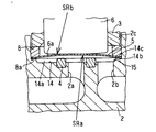
- FIG. 2 is an enlarged longitudinal sectional view showing a characteristic portion of the diaphragm valve according to the present invention.
- FIG. 3 is a diagram showing an analysis result when SRb / SRa is smaller than 0.4.
- FIG. 4 is a diagram showing an analysis result when SRb / SRa is larger than 0.6.
- FIG. 5 is a diagram showing an analysis result when SRb / SRa is 0.5.
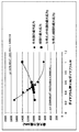
- FIG. 6 is a graph showing how the maximum stress at the center and the maximum stress at the edge change when SRb / SRa is changed when the diameter of the diaphragm is 15 ⁇ .
- FIG. 1 is a longitudinal sectional view showing the entire configuration of a diaphragm valve according to the present invention.
- FIG. 2 is an enlarged longitudinal sectional view showing a characteristic portion of the diaphragm valve according to the present
- FIG. 7 is a graph showing how the maximum stress at the center and the maximum stress at the edge change when SRb / SRa is changed when the diameter of the diaphragm is 20 ⁇ .
- FIG. 8 is a graph showing how the maximum stress at the center and the maximum stress at the edge change when SRb / SRa is changed when the diameter of the diaphragm is 26 ⁇ .
- Diaphragm valve (2) Valve box (2a) Fluid inflow passage (2b) Fluid outflow passage (4) Valve seat (5) Diaphragm (6) Diaphragm holder
- FIG. 1 shows the basic shape of a diaphragm valve (1) according to the present invention.
- the diaphragm valve (1) has a fluid inflow passage (2a), a fluid outflow passage (2b), and a recess ( 2c) a block-shaped valve box (2), a cylindrical bonnet (3) whose lower end is screwed onto the upper part of the recess (2c) of the valve box (2), and a fluid inflow passage
- An annular valve seat (4) provided at the periphery of (2a), a diaphragm (5) that opens or closes the fluid inflow passage (2a) by being pressed or separated by the valve seat (4), and a center of the diaphragm (5)
- a diaphragm presser (6) that presses the valve, and a stem (7) that is inserted into the bonnet (3) so as to be movable up and down and presses and separates the diaphragm (5) from the valve seat (4) via the diaphragm presser (6) Between the
- the actuator (10) includes a piston (11) integrated with the stem (7), a compression coil spring (biasing member) (12) that biases the piston (11) downward, and a lower surface of the piston (11).
- An operation air introduction chamber (13) provided, and an operation air introduction passage (7a) provided so as to penetrate the stem (7) and introduce operation air into the operation air introduction chamber (13) are provided. .
- the diaphragm (5) has a spherical shell shape, and an upwardly convex arc shape is in a natural state.
- the diaphragm (5) is made of, for example, a nickel alloy thin plate, and is formed in a spherical shell shape that is cut out in a circular shape and has a central portion bulged upward.
- the diaphragm (5) may be made of a stainless steel sheet or a laminate of a stainless steel sheet and a nickel / cobalt alloy sheet.
- the holding adapter (8) is tapered or arcuate with the entire lower surface (8a) at a predetermined inclination angle.
- the bottom surface (14) of the recess (2c) of the valve box (2) is continuous with the circular flat portion (14a) and the outer periphery of the flat portion (14a) and is recessed with respect to the flat portion (14a). And an annular recess (14b).
- the holding adapter (8) is fixed in a state where the bonnet (3) is in contact with the outer peripheral edge of the diaphragm (5) from above by screwing the bonnet (3) onto the valve box (2). At this time, the entire bottom surface (8a) of the holding adapter (8) is tapered, so that the diaphragm (5) is not deformed from the spherical shell shape (upwardly convex arc shape) and the outer surface of the diaphragm adapter (8) is almost completely deformed. With the upper surface of the peripheral edge in surface contact with the tapered lower surface (8a) of the retainer adapter (8) (contact in a wide range), the bottom surface of the recess (2c) in the retainer adapter (8) and valve box (2) ( 14) is held between.
- the recess (14b) is provided on the outer peripheral edge portion of the bottom surface (14) of the recess (2c) of the valve box (2), the outer peripheral edge portion of the diaphragm (5) is placed in the recess (14b). Is housed in. Therefore, the outer peripheral edge of the diaphragm (5) is not deformed along the bottom surface (14) of the recess (2c) of the valve box (2), and its lower surface is the bottom surface of the recess (2c) ( 14) is in line contact with the outer periphery (diaphragm support) (14c) of the flat portion (14a).
- the radius of curvature of the diaphragm (5) is optimized, and then the radius of curvature of the pressing surface of the diaphragm retainer (6) is set as the radius of curvature of the diaphragm (5).
- the curvature radii were set in the order of setting the same or slightly smaller values.
- the curvature radius of the diaphragm (5) is SRa
- the curvature radius of the pressing surface of the diaphragm retainer (6) is SRb
- the relationship between SRb / SRa and the stress generated in the diaphragm (5) is determined using a finite element method.
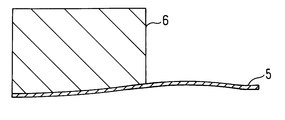
- FIGS. 3 to 5 show how the diaphragm (5) is deformed when the diaphragm valve (1) is closed by the diaphragm holder (6).
- 3 shows a case where SRb / SRa is smaller than 0.4
- FIG. 4 shows a case where SRb / SRa is larger than 0.6
- FIG. 5 shows a case where SRb / SRa is 0.5.
- Each one is shown.
- the stress distribution of each figure it has simplified and shown by enclosing the part with large stress value in a circle.
- the stress is maximum at the central portion of the diaphragm (5) indicated by A in the same figure, and the value is about 1400 MPa.
- the stress is maximum at the edge of the diaphragm (5) indicated by B in the same figure, and the value is about 1100 MPa.
- the stress is uniformed at the center and the edge of the diaphragm (5), and the maximum value of the stress is about 1000 MPa.
- FIG. 6 shows a case where the diameter of the diaphragm (5) is 15 ⁇
- FIG. 7 shows a case where the diameter of the diaphragm (5) is 20 ⁇
- FIG. 8 shows a case where the diameter of the diaphragm (5) is 26 ⁇ .
- the central maximum stress tends to decrease as SRb / SRa increases, and the edge maximum stress tends to increase as SRb / SRa increases.
- the maximum stress at the edge portion and the central portion is at most about 1000 MPa or less.
- the actuator (10) for moving the stem (7) to be moved up and down is configured, but the configuration of the actuator is not limited to that shown in FIG.
- the present invention is suitable as a direct touch type metal diaphragm valve used in a gas supply system of a semiconductor manufacturing facility, and the durability of the diaphragm is improved, which can contribute to an improvement in performance of the semiconductor manufacturing facility.
Landscapes
- Engineering & Computer Science (AREA)
- General Engineering & Computer Science (AREA)
- Mechanical Engineering (AREA)
- Diaphragms And Bellows (AREA)
- Fluid-Driven Valves (AREA)
Abstract
Description
(2) 弁箱
(2a)流体流入通路
(2b)流体流出通路
(4) 弁座
(5) ダイヤフラム
(6) ダイヤフラム押さえ
Claims (1)
- 流体通路が設けられた弁箱と、流体通路の周縁に設けられた弁座と、弁座に押圧または離間されて流体通路を開閉する球面状のダイヤフラムと、下端に球面状の押圧面を有しダイヤフラムを押圧するダイヤフラム押さえと、ダイヤフラムを上下移動させるアクチュエータとを備えているダイヤフラム弁において、
ダイヤフラムの曲率半径をSRa、ダイヤフラム押さえの押圧面の曲率半径をSRbとして、SRb/SRa=0.4~0.6とされているダイヤフラム弁。
Priority Applications (3)
| Application Number | Priority Date | Filing Date | Title |
|---|---|---|---|
| CN201680017445.8A CN107407430B (zh) | 2015-03-25 | 2016-03-04 | 隔膜阀 |
| KR1020177024845A KR20170109062A (ko) | 2015-03-25 | 2016-03-04 | 다이어프램 밸브 |
| US15/559,980 US10371270B2 (en) | 2015-03-25 | 2016-03-04 | Diaphragm valve |
Applications Claiming Priority (2)
| Application Number | Priority Date | Filing Date | Title |
|---|---|---|---|
| JP2015062343A JP6564593B2 (ja) | 2015-03-25 | 2015-03-25 | ダイヤフラム弁 |
| JP2015-062343 | 2015-03-25 |
Publications (1)
| Publication Number | Publication Date |
|---|---|
| WO2016152457A1 true WO2016152457A1 (ja) | 2016-09-29 |
Family
ID=56978344
Family Applications (1)
| Application Number | Title | Priority Date | Filing Date |
|---|---|---|---|
| PCT/JP2016/056752 Ceased WO2016152457A1 (ja) | 2015-03-25 | 2016-03-04 | ダイヤフラム弁 |
Country Status (6)
| Country | Link |
|---|---|
| US (1) | US10371270B2 (ja) |
| JP (1) | JP6564593B2 (ja) |
| KR (1) | KR20170109062A (ja) |
| CN (1) | CN107407430B (ja) |
| TW (1) | TWI690670B (ja) |
| WO (1) | WO2016152457A1 (ja) |
Cited By (1)
| Publication number | Priority date | Publication date | Assignee | Title |
|---|---|---|---|---|
| JPWO2019193978A1 (ja) * | 2018-04-06 | 2021-06-17 | 株式会社フジキン | バルブ装置および流体制御装置、流体制御方法、半導体製造装置及び半導体製造方法 |
Families Citing this family (4)
| Publication number | Priority date | Publication date | Assignee | Title |
|---|---|---|---|---|
| JP6920075B2 (ja) * | 2017-02-27 | 2021-08-18 | 株式会社キッツエスシーティー | ダイヤフラムバルブの取付構造とダイヤフラムバルブの着脱方法 |
| TWI692593B (zh) | 2018-09-05 | 2020-05-01 | 和正豐科技股份有限公司 | 膜片閥構造及膜片閥的熱源隔離方法 |
| JP2025005544A (ja) | 2023-06-28 | 2025-01-17 | Ckd株式会社 | 流体制御弁 |
| JP2025014385A (ja) | 2023-07-18 | 2025-01-30 | Ckd株式会社 | 流体制御弁 |
Citations (2)
| Publication number | Priority date | Publication date | Assignee | Title |
|---|---|---|---|---|
| JPS5597568A (en) * | 1979-01-18 | 1980-07-24 | Utsue Valve Kk | Stem head of diaphragm valve |
| JP2014009765A (ja) * | 2012-06-29 | 2014-01-20 | Fujikin Inc | ダイヤフラム弁 |
Family Cites Families (11)
| Publication number | Priority date | Publication date | Assignee | Title |
|---|---|---|---|---|
| JPH0515660Y2 (ja) | 1988-08-12 | 1993-04-23 | ||
| US4977929B1 (en) * | 1989-06-28 | 1995-04-04 | Fluoroware Inc | Weir valve sampling/injection port |
| JPH06294471A (ja) | 1993-04-05 | 1994-10-21 | Kiyohara Masako | ダイヤフラム型流体制御器 |
| JP3280119B2 (ja) * | 1993-06-02 | 2002-04-30 | 清原 まさ子 | ダイヤフラム弁 |
| US5730423A (en) * | 1996-10-16 | 1998-03-24 | Parker-Hannifin Corporation | All metal diaphragm valve |
| KR100514761B1 (ko) * | 1997-02-03 | 2005-09-15 | 스와겔로크 컴패니 | 다이어프램 밸브 |
| TW572164U (en) * | 2002-12-06 | 2004-01-11 | Ind Tech Res Inst | Diaphragm valve |
| US20050109973A1 (en) * | 2003-11-21 | 2005-05-26 | Glime William H. | Valve diaphragm |
| DE102009030186A1 (de) * | 2009-06-24 | 2011-01-05 | Joachim Kern | Membranventil |
| JP5565856B2 (ja) * | 2010-03-24 | 2014-08-06 | セイコーインスツル株式会社 | ダイアフラム、ダイアフラムバルブ、及びダイアフラムの製造方法 |
| JP6336345B2 (ja) * | 2014-06-30 | 2018-06-06 | 株式会社フジキン | ダイヤフラム弁、流体制御装置、半導体製造装置および半導体製造方法 |
-
2015
- 2015-03-25 JP JP2015062343A patent/JP6564593B2/ja active Active
-
2016
- 2016-03-04 WO PCT/JP2016/056752 patent/WO2016152457A1/ja not_active Ceased
- 2016-03-04 CN CN201680017445.8A patent/CN107407430B/zh not_active Expired - Fee Related
- 2016-03-04 US US15/559,980 patent/US10371270B2/en active Active
- 2016-03-04 KR KR1020177024845A patent/KR20170109062A/ko not_active Ceased
- 2016-03-24 TW TW105109120A patent/TWI690670B/zh active
Patent Citations (2)
| Publication number | Priority date | Publication date | Assignee | Title |
|---|---|---|---|---|
| JPS5597568A (en) * | 1979-01-18 | 1980-07-24 | Utsue Valve Kk | Stem head of diaphragm valve |
| JP2014009765A (ja) * | 2012-06-29 | 2014-01-20 | Fujikin Inc | ダイヤフラム弁 |
Cited By (2)
| Publication number | Priority date | Publication date | Assignee | Title |
|---|---|---|---|---|
| JPWO2019193978A1 (ja) * | 2018-04-06 | 2021-06-17 | 株式会社フジキン | バルブ装置および流体制御装置、流体制御方法、半導体製造装置及び半導体製造方法 |
| JP7257056B2 (ja) | 2018-04-06 | 2023-04-13 | 株式会社フジキン | バルブ装置および流体制御装置、流体制御方法、半導体製造装置及び半導体製造方法 |
Also Published As
| Publication number | Publication date |
|---|---|
| TWI690670B (zh) | 2020-04-11 |
| US10371270B2 (en) | 2019-08-06 |
| TW201702508A (zh) | 2017-01-16 |
| JP6564593B2 (ja) | 2019-08-21 |
| CN107407430B (zh) | 2019-10-22 |
| JP2016180490A (ja) | 2016-10-13 |
| KR20170109062A (ko) | 2017-09-27 |
| US20180106385A1 (en) | 2018-04-19 |
| CN107407430A (zh) | 2017-11-28 |
Similar Documents
| Publication | Publication Date | Title |
|---|---|---|
| JP6564593B2 (ja) | ダイヤフラム弁 | |
| JP6336345B2 (ja) | ダイヤフラム弁、流体制御装置、半導体製造装置および半導体製造方法 | |
| JP5933370B2 (ja) | ダイヤフラム弁 | |
| JP6072648B2 (ja) | ダイヤフラム弁 | |
| KR101599117B1 (ko) | 다이어프램 밸브 및 다이어프램 밸브용 시트 홀더 유닛 | |
| JP6335685B2 (ja) | ダイヤフラム弁、流体制御装置、半導体製造装置および半導体製造方法 | |
| WO2013084744A1 (ja) | ダイヤフラム弁 | |
| KR101907283B1 (ko) | 유체 제어기 | |
| JP5779559B2 (ja) | ダイヤフラム弁 | |
| JP5364051B2 (ja) | 流体制御弁 | |
| JP2609400B2 (ja) | ダイヤフラム弁のダイヤフラム | |
| JP2018132194A (ja) | ダイヤフラム弁、流体制御装置、半導体制御装置および半導体制御方法 | |
| JP2015048862A (ja) | ダイヤフラム弁 |
Legal Events
| Date | Code | Title | Description |
|---|---|---|---|
| 121 | Ep: the epo has been informed by wipo that ep was designated in this application |
Ref document number: 16768360 Country of ref document: EP Kind code of ref document: A1 |
|
| ENP | Entry into the national phase |
Ref document number: 20177024845 Country of ref document: KR Kind code of ref document: A |
|
| WWE | Wipo information: entry into national phase |
Ref document number: 15559980 Country of ref document: US |
|
| NENP | Non-entry into the national phase |
Ref country code: DE |
|
| 122 | Ep: pct application non-entry in european phase |
Ref document number: 16768360 Country of ref document: EP Kind code of ref document: A1 |