WO2016152342A1 - 液状化学物質のためのタンク - Google Patents
液状化学物質のためのタンク Download PDFInfo
- Publication number
- WO2016152342A1 WO2016152342A1 PCT/JP2016/054709 JP2016054709W WO2016152342A1 WO 2016152342 A1 WO2016152342 A1 WO 2016152342A1 JP 2016054709 W JP2016054709 W JP 2016054709W WO 2016152342 A1 WO2016152342 A1 WO 2016152342A1
- Authority
- WO
- WIPO (PCT)
- Prior art keywords
- valve means
- chemical substance
- flow path
- gas
- tank
- Prior art date
- Legal status (The legal status is an assumption and is not a legal conclusion. Google has not performed a legal analysis and makes no representation as to the accuracy of the status listed.)
- Ceased
Links
Images



Classifications
-
- B—PERFORMING OPERATIONS; TRANSPORTING
- B65—CONVEYING; PACKING; STORING; HANDLING THIN OR FILAMENTARY MATERIAL
- B65D—CONTAINERS FOR STORAGE OR TRANSPORT OF ARTICLES OR MATERIALS, e.g. BAGS, BARRELS, BOTTLES, BOXES, CANS, CARTONS, CRATES, DRUMS, JARS, TANKS, HOPPERS, FORWARDING CONTAINERS; ACCESSORIES, CLOSURES, OR FITTINGS THEREFOR; PACKAGING ELEMENTS; PACKAGES
- B65D90/00—Component parts, details or accessories for large containers
-
- F—MECHANICAL ENGINEERING; LIGHTING; HEATING; WEAPONS; BLASTING
- F17—STORING OR DISTRIBUTING GASES OR LIQUIDS
- F17C—VESSELS FOR CONTAINING OR STORING COMPRESSED, LIQUEFIED OR SOLIDIFIED GASES; FIXED-CAPACITY GAS-HOLDERS; FILLING VESSELS WITH, OR DISCHARGING FROM VESSELS, COMPRESSED, LIQUEFIED, OR SOLIDIFIED GASES
- F17C13/00—Details of vessels or of the filling or discharging of vessels
- F17C13/04—Arrangement or mounting of valves
Definitions
- a chemical substance consumption source such as a liquid chemical substance production apparatus is loaded with the liquid chemical substance and transported to a position equipped with the chemical substance consumption apparatus located at a distance from the chemical substance supply source to consume the chemical substance It relates to a tank that is used repeatedly to supply liquid chemicals to the device.
- an epitaxial wafer manufacturing apparatus is required to supply high purity trichlorosilane, and generally, the following supply mode is employed.
- the tank is filled with liquid high purity trichlorosilane produced in the high purity trichlorosilane production apparatus, and the tank is transported to a region equipped with the epitaxial wafer production apparatus, and the high purity trichlorosilane loaded in the tank is Supply to epitaxial manufacturing equipment.
- the tank is returned to the area equipped with the trichlorosilane production apparatus for reuse, and the tank is again filled with high purity trichlorosilane.
- the tank comprises a tank body and a connection unit attached to the tank body.
- the connection unit extends from a chemical flow path having an immersion portion immersed in a liquid chemical substance such as high purity trichlorosilane in the tank body and an extension portion extending from the tank body and one end communicated with the tank body And an outlet gas flow path.
- On-off valve means is disposed in the chemical substance flow path, and on-off valve means is also disposed in the gas flow path.
- Patent Document 1 also describes cleaning the connection unit with an inert gas such as helium (although the manner of cleaning is not necessarily clearly described).
- the present invention has been made in view of the above-mentioned facts, and its main technical problem is not particularly limited thereto, but it is suitably used as a tank for high purity liquid chemicals such as high purity trichlorosilane. It is an object of the present invention to provide a tank for an improved liquid chemical, which can be used, wherein contamination of the liquefaction chemical is prevented as much as possible.
- connection unit attached to the tank body unique by arranging double on-off valve means in each of the chemical substance flow path and the gas flow path. It has been found that the above-mentioned main technical problems can be solved.
- a liquid chemical substance comprising a tank main body and a connection unit attached to the tank main body.
- the connection unit extends from a chemical substance flow path having an immersion part immersed in a chemical substance in the tank body and an extension part extending from the tank body, and one end communicated with the inside of the tank body Including gas channels,
- first on-off valve means positioned downstream as viewed in the chemical substance filling direction into the tank body, and upstream position as viewed in the chemical substance filling direction Second on-off valve means is provided.
- the gas flow path is provided with third on-off valve means located downstream as viewed in the gas inflow direction to the tank main body and fourth on-off valve means located upstream as viewed from the gas inflow direction.
- third on-off valve means located downstream as viewed in the gas inflow direction to the tank main body
- fourth on-off valve means located upstream as viewed from the gas inflow direction.
- the present invention is applied to a chemical substance supply source provided with a connection adapter and a chemical substance consumption device provided with a connection adapter,
- Each of the connection adapters has one end connected to the chemical source or the chemical consumption device, and the other end connected to the chemical connection flow path connected to the extended end of the chemical flow path, and one end abatement means The other end is connected to the extended end of the gas flow path, the other end is connected to the chemical substance connection flow path, and the other end is connected to the gas supply source.
- a first gas supply flow path, and a second gas supply flow path connected at one end to the gas connection flow path and at the other end to the gas supply source In the chemical substance connection flow channel, sixth on-off valve means positioned downstream of the one end of the first gas supply flow channel as seen in the direction of the inside of the tank main body, and in the tank main body A seventh on-off valve means positioned upstream of the one end of the first gas supply flow passage in the direction; In the gas connection flow channel, an eighth on-off valve means positioned downstream of the one end of the second gas supply flow channel when viewed in the direction toward the inside of the tank main body, and a direction toward the inside of the tank main body A ninth on-off valve located upstream of the one end of the second gas supply flow passage, as viewed in A tenth on-off valve means is disposed in the first gas supply flow path, An eleventh on-off valve means is disposed in the second gas supply passage.
- the tank of the present invention when the tank body is filled with the liquid chemical substance in the area equipped with the liquid chemical substance manufacturing device, the tank filled with the liquid chemical substance When transporting the tank body chemical to the chemical substance consumption device in the area equipped with the chemical substance consumption device when transporting the tank with the chemical substance consumption device, and Contamination of the chemical substance is sufficiently prevented in any case when the tank where the substance is consumed is returned to the area equipped with the chemical substance production apparatus.
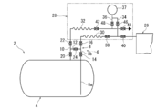
- FIG. 1 is a simplified diagram illustrating a preferred embodiment of a tank constructed in accordance with the present invention.
- FIG. 2 is a partial plan view of the tank illustrated in FIG. 1;
- FIG. 2 is a simplified view for explaining the manner of use of the tank when filling the liquid chemical into the tank body of the tank illustrated in FIG. 1;
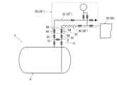
- 1 is a simplified diagram for explaining the tank usage pattern when supplying liquid chemical substances from inside the tank body of the illustrated tank to the chemical substance consumption device.
- FIG. 2 is a simplified view of an additional connection unit applied to the tank illustrated in FIG. 1;
- the tank 2 constructed in accordance with the present invention comprises a tank body 4 and a connection unit 6 attached to the tank body 4.
- the tank body 4 which can be made of an appropriate material such as stainless steel may have an appropriate hollow structure, but in the illustrated embodiment, it has a cylindrical shape elongated in the lateral direction (left and right direction in FIG. 1) And both side surfaces (left side and right side in FIG. 1) are convex.
- the connection unit 6 is attached to the upper surface of such a tank body 4.
- connection unit 6 includes the chemical substance flow path 8, the gas flow path 10 and the connection flow path 12.
- the chemical substance flow path 8 has an immersion portion 8 a to be immersed in a liquid chemical substance (not shown) filled in the tank main body 4 and an extending portion 8 b extending from the tank main body 4.
- the extension portion 8b of the chemical substance flow passage 8 is provided with the on-off valve means, ie, the first on-off valve means 14 and the above-mentioned on-off valve means 14 located on the downstream side when viewed in the chemical substance filling direction
- An on-off valve means that is, a second on-off valve means 16 located upstream as viewed in the chemical substance filling direction is disposed.
- the second on-off valve means 16 is disposed at the extension end of the chemical substance flow passage 8.
- Such a chemical substance flow path 8 can be understood by referring to FIG. 2; the straight extending straight pipe member defining the flow path and the substantially right-angled curved elbow pipe member, the first on-off valve
- the straight extending straight pipe member defining the flow path and the substantially right-angled curved elbow pipe member, the first on-off valve Advantageously by connecting as appropriate the required valve members which make up the means 14 and the second on-off valve means 16, in the illustrated embodiment a ball valve member provided with a manually operated handle, Can.
- connection between the pipe members can be achieved by any suitable connection mode such as welding, and the connection of the valve member to the straight pipe member and the elbow pipe member is carried out by connecting a connection flange disposed at the end of the valve member This can be achieved by interposing an appropriate packing in a connection flange disposed at the end of the and fastening by an appropriate fastening means such as a bolt and a nut.
- the connection with the tank body 4 can be accomplished by connecting a flange 18 (FIG. 2) attached to the required portion of the pipe member in a state in which the opening formed in the tank body 4 is airtightly closed.
- the gas flow path 10 extends from one end of the tank body 4 in communication.
- the on-off valve means that is, the third on-off valve means 20 located on the downstream side when viewed in the gas inflow direction (downward in FIG. 1) to the tank main body 4,
- An on-off valve means or fourth on-off valve means 22 located on the upstream side is disposed.
- the fourth on-off valve means 22 is disposed at the extension end of the gas flow passage 10.
- the gas flow path 10 also includes a straight pipe member extending straight and an elbow pipe member curved substantially at right angles defining the flow path.
- a suitable valve member constituting the fourth on-off valve means 22, in the illustrated embodiment a ball valve member provided with a manual operation handle, can be conveniently constructed by interposing and connecting as required.
- the connection with the tank body 4 can be accomplished by connecting a flange 23 (FIG. 2) attached to the required portion of the pipe member in a state in which the opening formed in the tank body 4 is airtightly closed.
- the connecting flow channel 12 is a portion between the first on-off valve means 14 and the second on-off valve means 16 in the chemical substance flow channel 8 and the third on-off valve means 20 in the gas flow channel 10. It is connected with the part between the fourth on-off valve means 22. Further, an open / close valve means, that is, a fifth open / close valve means 24 is disposed in the connection flow path 12. As shown in FIG. 2, such a connecting channel 12 is a straight pipe member extending straight which defines the channel, an appropriate valve member constituting the fifth on-off valve means 24, and in the illustrated embodiment, A ball valve member with a manually operated handle can advantageously be constructed by interposing and connecting. One end (right end in FIG.
- connection flow channel 12 is in communication with the extension 8b of the chemical substance flow channel 8, and the other end (left end in FIG. 1) is in communication with the gas flow channel 10. More specifically, as shown in FIG. 2, one end of the pipe member constituting the connection flow channel 12 is connected to a connecting portion formed on the side surface of the pipe member constituting the chemical substance flow channel 8 to One end of another pipe member in communication with the substance flow channel 8 and constituting the connection flow channel 12 is connected to a connecting portion formed on the side surface of the pipe member constituting the gas flow channel 10 to be connected to the gas flow channel 10. It is in communication with
- the usage pattern of the tank 2 will be described as described above.
- the chemical substance supply source 26 such as the liquid chemical substance manufacturing equipment or the liquid chemical substance storage equipment It is carried into the existing area.
- a connection adapter 28 is attached to the chemical substance supply source 26.
- the connection adapter 28 includes a chemical connection channel 30 and a gas connection channel 32.
- One end of the chemical substance connection channel 30 is connected to the chemical substance supply source 26, and one end of the gas connection channel 32 is connected to the atmosphere via an appropriate abatement means (not shown) for rendering the chemical substance harmless. It is open.
- connection adapter 28 further includes a first gas supply channel 34 and a second gas supply channel 36.
- One end of the first gas supply flow path 34 is connected to the chemical substance connection flow path 30, and one end of the second gas supply flow path 36 is connected to the gas connection flow path 32.
- the other end of the first gas supply channel 34 and the other end of the second gas supply channel 36 are gas supplies for supplying a sealing gas composed of an inert gas such as argon, hydrogen, nitrogen and helium. Connected to the source 37.
- an on-off valve means that is, a second valve located on the downstream side of the one end of the first gas supply flow path 34 as viewed in the direction (leftward in FIG. 1)
- An on-off valve means ie, a seventh on-off valve means 40 positioned upstream of the one end of the first gas supply passage 34 as viewed in the direction toward the inside of the on-off valve means 38 and the tank body 4 is disposed.
- the gas connection passage 32 is an on-off valve means located downstream of the one end of the second gas supply passage 36 as viewed in the direction toward the inside of the tank body 4 (leftward in FIG. 1).
- An on-off valve means that is, a ninth on-off valve means 44 is disposed on the upstream side of the one end of the second gas supply passage 36 as viewed in the direction toward the inside of the on-off valve means 42 and the tank body 4. ing.
- on-off valve means ie, tenth on-off valve means 46 and on-off valve means, ie, eleventh on-off valve means 48 are provided It is done.
- the chemical substance connection flow path 30, the gas connection flow path 32, the first gas supply flow path 34, and the second gas supply flow path 36 appropriately connect appropriate pipe members through required on-off valve means.
- the on-off valve means may conveniently be comprised of a ball valve provided with a manually operated handle.
- the second on-off valve means 16, the fourth on-off valve means 22, the fifth on-off valve means 24 and the ninth on-off valve means 44 are opened, and the tenth on-off valve means 46 is also opened.
- the seal gas is made to flow in the chemical substance connection flow path 30 and the gas connection flow path 32 to purge the gas present in the chemical substance connection flow path 30 and the gas connection flow path 32.
- the tenth on-off valve means 46 is closed and the fifth on-off valve means 24 is closed.
- the first on-off valve means 14, the third on-off valve means 20, and the seventh on-off valve means 40 are opened, and thus from the chemical source 26 through the chemical connection channel 30 and the chemical channel 8.
- a liquid chemical is caused to flow into the tank body 4.
- the filling amount of the liquid chemical substance in the tank body 4 can be determined, for example, by placing the entire tank 2 on a load cell (not shown) via an appropriate chassis (not shown). It can be recognized by measuring the variation. Alternatively, it can be recognized by an integrated flow rate system provided in the chemical substance flow path 8 or the chemical substance connection flow path 30.
- the seventh on-off valve means 40 is closed to stop the filling, and the tenth on-off valve means 46 is opened to flow the chemical substance by the seal gas.
- the liquid chemical substance accumulated in the passage 30 and the chemical substance channel 8 is expelled into the tank body 4.
- the third on-off valve means 20 is closed to flow seal gas into the tank body 4 to apply a pressure of about 100 kPaG, and then the first on-off valve means 14 is closed. When the pressure is lowered by the absorption of the seal gas in the chemical substance, the first on-off valve means 14 is opened to allow the seal gas to flow to raise the pressure.
- the fifth on-off valve means 24 is opened, and the gas in the chemical substance connection channel 30 and the gas connection channel 32 is purged by the seal gas.
- the pressure release on-off valve means (not shown) disposed downstream of the sixth on-off valve means 38 as viewed in the direction of the tank body 4 in the chemical substance connection flow path 30, for example. And / or by opening on-off valve means (not shown) disposed downstream of the eighth on-off valve means 42 as viewed in the direction of the tank body 4 in the gas connection channel 32).
- the positive pressure in the substance connection flow path 30 and / or the gas connection flow path 32 is released.
- the chemical substance connection flow path 30 and the gas connection flow path 32 are separated from the chemical substance flow path 8 and the gas flow path 10 in the connection unit 6 of the tank 2, respectively.
- the tank 2 is allowed to be transported to an area separated from the area equipped with the chemical source 26 (the area equipped with a chemical consumption device described later). It is convenient to detachably attach an appropriate closing means (not shown) such as a fitting cap or an insertion plug to the extended end of the chemical substance flow passage 8 and the extended end of the gas flow passage 10. .
- the tank 2 filled with the required amount of liquid chemical substance in the tank main body 4 as described above is transported by a suitable transport means (not shown) such as a dedicated truck. It is transported to a region equipped with a chemical substance consumption device 50 such as an epitaxial wafer manufacturing device.
- the chemical substance consumption device 50 is provided with a connection adapter 28 '.
- the connection adapter 28 ' may be substantially identical to the connection adapter 28 illustrated in FIG. 3, ie the connection adapter 28 attached to the chemical source 26.
- each component of the connection adapter 28 ' is numbered by adding "'" to the number of the corresponding component in the connection adapter 28.
- the description of the configuration of the connection adapter 28 ' is omitted to avoid duplication of description.
- connection adapter 28 ′ attached to the chemical substance consumption device 50 is connected to the extension end of the chemical substance flow path 8 and the extension end of the gas flow path 10 in the unit 4 and thus to the connection unit 4 of the tank 2 Ru.
- Airtightness confirmation and 2. Gas displacement First, carried out in the filling of the above mentioned chemicals: Airtightness confirmation and 2. Airtightness verification and gas replacement are performed in the same manner as gas replacement. Then, the ninth on-off valve means 44 'is closed.
- the chemical substance supply device 50 is supplied through the chemical substance flow path and the chemical substance connection flow path 30 '.
- the supply amount of the liquid chemical substance to the chemical substance consumption device 50 in other words, the residual amount of the liquid chemical substance in the tank main body 4 is, for example, the whole of the tank 2 through the appropriate chassis (not shown). (Not shown) and can be recognized by measuring the weight variation of the tank 2.
- the auxiliary connection adapter 52 has one end adapted to connect to the extension end of the chemical flow channel 8 and the other end adapted to connect the other end of the chemical connection flow channel 30 (30 ') to the chemical auxiliary A connecting channel 54 and one end suitable for connecting to the extending end of the gas channel 10, and the other end being a gas auxiliary connecting channel suitable for connecting to the other end of the connecting channel 32 (32 ') And 56.
- a twelfth on-off valve means 58 and a thirteenth on-off valve means 60 are disposed in the chemical substance auxiliary connection flow path 54 and the auxiliary connection flow path 56, respectively.
- the twelfth on-off valve means 58 and the thirteenth on-off valve means 60 are respectively the second on-off valve means 16 and the fourth on-off valve means 22. Opens and closes according to the opening and closing of the
- Tank 4 Tank body 6: Connection unit 8: Chemical flow channel 10: Gas flow channel 12: Connection flow channel 14: first on-off valve means 16: second on-off valve means 20: third on-off valve Means 22: Fourth on-off valve means 24: Fifth on-off valve means 26: Chemical substance supply sources 28 and 28 ': Connection adapters 30 and 30': Chemical substance connection channels 32 and 32 ': Gas connection channels 34 And 34 ': first gas supply flow path 36 and 36': second gas supply flow path 37 and 37 ': gas supply source 38 and 38': sixth on-off valve means 40 and 40 ': seventh Opening and closing valve means 42 and 42 ': eighth opening and closing valve means 44 and 44': ninth opening and closing valve means 46 and 46 ': tenth opening and closing valve means 48 and 48': eleventh opening and closing valve means 50: Chemical substance consumption device 52: Auxiliary connection adapter Ter 54: Chemical auxiliary connection channel 56: air auxiliary connection channel 58: twelfth on-off valve means 60: a thirteenth-off valve means
Landscapes
- Engineering & Computer Science (AREA)
- Mechanical Engineering (AREA)
- General Engineering & Computer Science (AREA)
- Filling Or Discharging Of Gas Storage Vessels (AREA)
- Feeding, Discharge, Calcimining, Fusing, And Gas-Generation Devices (AREA)
Abstract
高純度トリクロロシランの如き高純度の液状化学物質のためのタンクとして好適に使用ことができる、液状化化学物質の汚染が可及的に防止される液状化学物質のためのタンク(2)。タンク(2)はタンク本体(4)とこのタンク本体(4)に付設された接続ユニット(6)とを具備する。接続ユニット(6)は、タンク本体(4)内の化学物質に浸漬される浸漬部(8a)及びタンク本体(4)から延出する延出部(8b)を有する化学物質流路(8)と、タンク本体(4)内に連通された片端から延出する気体流路(10)と含む。化学物質流路(8)の延出部(8b)には、タンク本体(4)内への化学物質充填方向に見て下流側に位置する第一の開閉弁手段(14)及び化学物質充填方向に見て上流側に位置する第二の開閉弁手段(16)が配設されている。気体流路(10)には、タンク本体(4)への気体流入方向に見て下流側に位置する第三の開閉弁手段(20)及び気体流入方向見て上流側に位置する第四の開閉弁手段(22)が配設されている。接続ユニット(6)は、更に、化学物質流路(8)における第一の開閉弁手段(14)と第二の開閉弁手段(16)との間の部位と気体流路(10)における第三の開閉弁部材(20)と第四の開閉弁手段(22)との間の部位とを連結する連結流路(12)を含む。連結流路(12)には第五の開閉弁手段(24)が配設されている。
Description
本発明は、液状化学物質製造装置の如き化学物質供給源から液状化学物質が充填され、化学物質供給源から離隔して位置する化学物質消費装置が装備されている位置まで搬送されて化学物質消費装置に液状化学物質を供給するのに繰り返し使用されるタンクに関する。
周知の如く、エピタキシャルウエーハ製造装置には高純度トリクロロシランを供給することが必要であり、一般に、次のとおりの供給様式が採用されている。高純度トリクロロシラン製造装置において製造された液状高純度トリクロロシランをタンクに充填し、かかるタンクをエピタキシャルウエーハ製造装置が装備されている領域まで搬送し、タンク内に充填されている高純度トリクロロシランをエピタキシャル製造装置に供給する。タンク内の高純度トリクロロシランが消費されると、再利用のためにタンクをトリクロロシラン製造装置が装備されている領域まで返送し、再びタンクに高純度トリクロロシランを充填する。
高純度トリククロシランの如き液状化学物質の上記のとおりの供給様式において使用されるタンクとしては、下記特許文献1に開示されているタンクを挙げることができる。かかるタンクはタンク本体とこのタンク本体に付設された接続ユニットとから構成されている。接続ユニットは、タンク本体内の高純度トリクロロシランの如き液状化学物質内に浸漬される浸漬部及びタンク本体から延出する延出部を有する化学物質流路とタンク本体に連通された片端から延出する気体流路とを含んでいる。化学物質流路中には開閉弁手段が配設され、気体流路中にも開閉弁手段が配設されている。更に、化学物質流路中の開閉弁手段と気体流路中の開閉弁手段とを連結する連結流路も配設され、この連結流路中にも開閉弁手段が配設されている。特許文献1には、接続ユニットをヘリウムの如き不活性気体で洗浄することも記載されている(しかしながら、洗浄様式については必ずしも明確に記載されていない)。
而して、高純度トリクロロシランの如き化学物質は大気或いは水液等に接触して汚染されることが可及的に防止され高純度が維持されることが重要であるが、上記特許文献1に開示されているタンクにおいては、化学物質流路及び気体流路の各々には単一の開閉弁手段しか配設されておらず、汚染の防止が必ずしも充分ではない。
本発明は上記事実に鑑みてなされたものであり、その主たる技術的課題は、特にそれに限定されるものではないが、高純度トリクロロシランの如き高純度の液状化学物質のためのタンクとして好適に使用ことができる、液状化化学物質の汚染が可及的に防止される改良された液状化学物質のためのタンクを提供することである。
本発明者等は、鋭意研究及び事件の結果、タンク本体に付設する接続ユニットを、化学物質流路及び気体流路の各々に2重の開閉弁手段を配設した独特な構成にすることによって上記主たる技術的課題を解決することができることを見出した。
即ち、本発明によれば、上記主たる技術的課題を達成することができる液状化学物質のためのタンクとして、タンク本体と該タンク本体に付設された接続ユニットとを具備する液状化学物質のためのタンクにして、
該接続ユニットは、該タンク本体内の化学物質に浸漬される浸漬部及び該タンク本体から延出する延出部を有する化学物質流路と、該タンク本体内に連通された片端から延出する気体流路と含み、
該化学物質流路の該延出部には、該タンク本体内への化学物質充填方向に見て下流側に位置する第一の開閉弁手段及び該化学物質充填方向に見て上流側に位置する第二の開閉弁手段が配設されており、
該気体流路には、該タンク本体への気体流入方向に見て下流側に位置する第三の開閉弁手段及び該気体流入方向見て上流側に位置する第四の開閉弁手段が配設されており、
更に、該化学物質流路における該第一の開閉弁手段と該第二の開閉弁手段との間の部位と該気体流路における該第三の開閉弁部材と該第四の開閉弁手段との間の部位とを連結する連結流路を含み、該連結流路には第五の開閉弁手段が配設されている、
ことを特徴とするタンクが提供される。
該接続ユニットは、該タンク本体内の化学物質に浸漬される浸漬部及び該タンク本体から延出する延出部を有する化学物質流路と、該タンク本体内に連通された片端から延出する気体流路と含み、
該化学物質流路の該延出部には、該タンク本体内への化学物質充填方向に見て下流側に位置する第一の開閉弁手段及び該化学物質充填方向に見て上流側に位置する第二の開閉弁手段が配設されており、
該気体流路には、該タンク本体への気体流入方向に見て下流側に位置する第三の開閉弁手段及び該気体流入方向見て上流側に位置する第四の開閉弁手段が配設されており、
更に、該化学物質流路における該第一の開閉弁手段と該第二の開閉弁手段との間の部位と該気体流路における該第三の開閉弁部材と該第四の開閉弁手段との間の部位とを連結する連結流路を含み、該連結流路には第五の開閉弁手段が配設されている、
ことを特徴とするタンクが提供される。
好適には、接続アダプターが付設された化学物質供給源及び接続アダプターが付設された化学物質消費装置に適用され、
該接続アダプターの各々は、片端は化学物質供給源又は該化学物質消費装置に接続され他端は該化学物質流路の延出端に接続される化学物質接続流路と、片端は除害手段を介して大気に連通され他端は該気体流路の延出端に接続される気体接続流路と、片端は該化学物質接続流路に接続され他端は気体供給源に接続されている第一の気体供給流路と、片端は該気体接続流路に接続され他端は該気体供給源に接続されている第二の気体供給流路とを含み、
該化学物質接続流路には、該タンク本体内に向かう方向に見て該第一の気体供給流路の該片端よりも下流側に位置する第六の開閉弁手段及び該タンク本体内に向かう方向に見て該第一の気体供給流路の該片端よりも上流側に位置する第七の開閉弁手段が配設されており、
該気体接続流路には、該タンク本体内に向かう方向に見て該第二の気体供給流路の該片端よりも下流側に位置する第八の開閉弁手段及び該タンク本体内に向かう方向に見て該第二の気体供給流路の該片端よりも上流側に位置する第九の開閉弁手段が配設されており、
該第一の気体供給流路には、第十の開閉弁手段が配設されており、
該第二の気体供給流路には、第十一の開閉弁手段が配設されている。
該接続アダプターの各々は、片端は化学物質供給源又は該化学物質消費装置に接続され他端は該化学物質流路の延出端に接続される化学物質接続流路と、片端は除害手段を介して大気に連通され他端は該気体流路の延出端に接続される気体接続流路と、片端は該化学物質接続流路に接続され他端は気体供給源に接続されている第一の気体供給流路と、片端は該気体接続流路に接続され他端は該気体供給源に接続されている第二の気体供給流路とを含み、
該化学物質接続流路には、該タンク本体内に向かう方向に見て該第一の気体供給流路の該片端よりも下流側に位置する第六の開閉弁手段及び該タンク本体内に向かう方向に見て該第一の気体供給流路の該片端よりも上流側に位置する第七の開閉弁手段が配設されており、
該気体接続流路には、該タンク本体内に向かう方向に見て該第二の気体供給流路の該片端よりも下流側に位置する第八の開閉弁手段及び該タンク本体内に向かう方向に見て該第二の気体供給流路の該片端よりも上流側に位置する第九の開閉弁手段が配設されており、
該第一の気体供給流路には、第十の開閉弁手段が配設されており、
該第二の気体供給流路には、第十一の開閉弁手段が配設されている。
本発明のタンクによれば、後の説明から明確に理解される如く、液状化学物質製造装置が装備されている領域においてタンク本体に液状化学物質を充填する際、液状化学物質が充填されたタンクを化学物質消費装置が装備されている領域迄タンクを搬送する際、化学物質消費装置が装備されている領域においてタンク本体の化学物質を化学物質消費装置に供給する際、及びタンク本体内の化学物質が消費されたタンクを化学物質製造装置が装備されている領域に返送する際のいずれにおいても、化学物質が汚染されてしまうことが充分確実に防止される。
以下、添付図面を参照して本発明に従って構成されたタンクについて更に詳細に説明する。
図1を参照して説明すると、本発明に従って構成されたタンク2は、タンク本体4とこのタンク本体4に付設された接続ユニット6とから構成されている。ステンレス鋼の如き適宜の材料から構成することができるタンク本体4は、適宜の中空構造でよいが、図示の実施形態においては横方向(図1において左右方向)に細長く延在する円筒形状であり且つ両側面(図1において左側面及び右側面)は凸形状である。そして、かようなタンク本体4の上面に接続ユニット6が付設されている。
図1と共に図2を参照して説明を続けると、接続ユニット6は化学物質流路8、気体流路10及び連結流路12を含んでいる。
化学物質流路8はタンク本体4内に充填される液状化学物質(図示していない)に浸漬される浸漬部8aとタンク本体4から延出する延出部8bとを有する。化学物質流路8の延出部8bには、タンク本体4への化学物質充填方向(図1において下向)に見て下流側に位置する開閉弁手段即ち第一の開閉弁手段14と上記化学物質充填方向に見て上流側に位置する開閉弁手段即ち第二の開閉弁手段16とが配設されている。図示の実施形態においては、第二の開閉弁手段16は化学物質流路8の延出端に配設されている。かような化学物質流路8は、図2を参照することによって理解される如く、流路を規定する真直に延びる真直管部材及び略直角に湾曲されたエルボ管部材を、第一の開閉弁手段14及び第二の開閉弁手段16を構成する適宜の弁部材、図示の実施形態においては手動操作ハンドルを備えたボール弁部材、を所要とおりに介在せしめて連結することによって好都合に構成することができる。管部材間の相互連結は溶接の如き適宜の連結様式によって達成することができ、真直管部材及びエルボ管部材に対する弁部材の連結は、弁部材の端に配設されている連結フランジを管部材の端に配設されている連結フランジに適宜のパッキンを介在させてボルト及びナットの如き適宜の締結手段によって締結することによって達成することができる。タンク本体4との連結は、管部材の所要部位に付設されたフランジ18(図2)をタンク本体4に形成された開口を気密に閉じる状態に連結することによって遂行することができる。
上記気体流路10はタンク本体4内に連通された片端から延出している。かかる気体流路10には、タンク本体4への気体流入方向(図1において下向)に見て下流側に位置する開閉弁手段即ち第三の開閉弁手段20と上記気体流入方向に見て上流側に位置する開閉弁手段即ち第四の開閉弁手段22とが配設されている。図示の実施形態においては、第四の開閉弁手段22は気体流路10の延出端に配設されている。かような気体流路10も、上記化学物質流路8と同様に、流路を規定する真直に延びる真直管部材及び略直角に湾曲されたエルボ管部材を、第三の開閉弁手段20及び第四の開閉弁手段22を構成する適宜の弁部材、図示の実施形態においては手動操作ハンドルを備えたボール弁部材、を所要とおりに介在せしめて連結することによって好都合に構成することができる。タンク本体4との連結は、管部材の所要部位に付設されたフランジ23(図2)をタンク本体4に形成されている開口を気密に閉じる状態に連結することによって遂行することができる。
上記連結流路12は、上記化学物質流路8における第一の開閉弁手段14と第二の開閉弁手段16との間の部位と上記気体流路10における上記第三の開閉弁手段20と第四の開閉弁手段22との間の部位とを連結している。そして、かかる連結流路12には、開閉弁手段即ち第五の開閉弁手段24が配設されている。かような連結流路12は、図2に図示する如く、流路を規定する真直に延びる真直管部材を、第五の開閉弁手段24を構成する適宜の弁部材、図示の実施形態においては手動操作ハンドルを備えたボール弁部材、を介在せしめて連結することによって好都合に構成することができる。連結流路12の片端(図1において右端)は上記化学物質流路8の延出部8bに連通され、他端(図1においおて左端)は上記気体流路10に連通されている。更に詳細には、図2に図示する如く、連結流路12を構成する管部材の片端は上記化学物質流路8を構成する管部材の側面に形成されている接続部に接続されて上記化学物質流路8に連通され、連結流路12を構成する他の管部材の片端は上記気体流路10を構成する管部材の側面に形成されている接続部に接続されて上記気体流路10に連通されている。
次に、上記のとおりタンク2の使用様式について説明する。
[化学物質の充填]
図3を参照して説明すると、タンク2のタンク本体4内にトリクロロシランの如き液状化学物質を充填する際には、液状化学物質製造設備或いは液状化学物質貯留設備の如き化学物質供給源26が存在する領域に搬入される。化学物質供給源26には接続アダプター28が付設されている。この接続アダプター28は、化学物質接続流路30及び気体接続流路32を含んでいる。化学物質接続流路30の片端は化学物質供給源26に接続されており、気体接続流路32の片端は化学物質を無害化する適宜の除害手段(図示していない)を介して大気に開放されている。一方、化学物質接続流路30の他端及び気体接続流路32の他端は、タンク本体4内に液状化学物質を充填する際に、夫々、タンク2の接続ユニット6における化学物質流路8の延出端及び気体流路10の延出端に接続される。接続アダプター28は、更に、第一の気体供給流路34及び第二の気体供給流路36を含んでいる。第一の気体供給流路34の片端は化学物質接続流路30に接続され、第二の気体供給流路36の片端は気体接続流路32に接続されている。第一の気体供給流路34の他端及び第二の気体供給流路36の他端は、アルゴン、水素、窒素及びヘリウムの如き不活性ガスから構成されるシールガスを供給するための気体供給源37に接続されている。上記化学物質接続流路30には、タンク本体4内に向かう方向(図1において左向)に見て上記第一の気体供給流路34の上記片端よりも下流側位置する開閉弁手段即ち第六の開閉弁手段38とタンク本体4内に向かう方向に見て上記第一の気体供給流路34の上記片端よりも上流側位置する開閉弁手段即ち第七の開閉弁手段40が配設されている。上記気体接続流路32には、タンク本体4内に向かう方向(図1において左向)に見て上記第二の気体供給流路36の上記片端よりも下流側に位置する開閉弁手段即ち第八の開閉弁手段42とタンク本体4内に向かう方向に見て上記第二の気体供給流路36の上記片端よりも上流側位置する開閉弁手段即ち第九の開閉弁手段44が配設されている。上記第一の空気供給流路34及び第二の空気供給流路36には、夫々、開閉弁手段即ち第十の開閉弁手段46及び開閉弁手段即ち第十一の開閉弁手段48が配設されている。上記化学物質接続流路30、気体接続流路32、第一の気体供給流路34及び第二の気体供給流路36は、適宜の管部材を所要開閉弁手段を介して適宜に連結することによって構成することができる。開閉弁手段は手動操作ハンドルを備えたボール弁から好都合に構成することができる。
[化学物質の充填]
図3を参照して説明すると、タンク2のタンク本体4内にトリクロロシランの如き液状化学物質を充填する際には、液状化学物質製造設備或いは液状化学物質貯留設備の如き化学物質供給源26が存在する領域に搬入される。化学物質供給源26には接続アダプター28が付設されている。この接続アダプター28は、化学物質接続流路30及び気体接続流路32を含んでいる。化学物質接続流路30の片端は化学物質供給源26に接続されており、気体接続流路32の片端は化学物質を無害化する適宜の除害手段(図示していない)を介して大気に開放されている。一方、化学物質接続流路30の他端及び気体接続流路32の他端は、タンク本体4内に液状化学物質を充填する際に、夫々、タンク2の接続ユニット6における化学物質流路8の延出端及び気体流路10の延出端に接続される。接続アダプター28は、更に、第一の気体供給流路34及び第二の気体供給流路36を含んでいる。第一の気体供給流路34の片端は化学物質接続流路30に接続され、第二の気体供給流路36の片端は気体接続流路32に接続されている。第一の気体供給流路34の他端及び第二の気体供給流路36の他端は、アルゴン、水素、窒素及びヘリウムの如き不活性ガスから構成されるシールガスを供給するための気体供給源37に接続されている。上記化学物質接続流路30には、タンク本体4内に向かう方向(図1において左向)に見て上記第一の気体供給流路34の上記片端よりも下流側位置する開閉弁手段即ち第六の開閉弁手段38とタンク本体4内に向かう方向に見て上記第一の気体供給流路34の上記片端よりも上流側位置する開閉弁手段即ち第七の開閉弁手段40が配設されている。上記気体接続流路32には、タンク本体4内に向かう方向(図1において左向)に見て上記第二の気体供給流路36の上記片端よりも下流側に位置する開閉弁手段即ち第八の開閉弁手段42とタンク本体4内に向かう方向に見て上記第二の気体供給流路36の上記片端よりも上流側位置する開閉弁手段即ち第九の開閉弁手段44が配設されている。上記第一の空気供給流路34及び第二の空気供給流路36には、夫々、開閉弁手段即ち第十の開閉弁手段46及び開閉弁手段即ち第十一の開閉弁手段48が配設されている。上記化学物質接続流路30、気体接続流路32、第一の気体供給流路34及び第二の気体供給流路36は、適宜の管部材を所要開閉弁手段を介して適宜に連結することによって構成することができる。開閉弁手段は手動操作ハンドルを備えたボール弁から好都合に構成することができる。
タンク2の接続ユニット6と化学物質供給源26に付設されている接続アダプター28とを図3に示すとおりに接続した後には、次のとおりの工程が遂行される。
1.気密確認
第一乃至第十一の開閉弁手段14、16、20、22、24、38、40、42、44、46及び48が閉である初期状態において、第六の開閉弁手段38及び第八の開閉弁手段42を開とし、そしてまた第十の開閉弁制御手段46及び第十一の開閉弁手段48を開とし、かくして化学物質接続流路30及び気体接続流路32にシールガスを送給する。次いで、全設備において気密が確保されているか否か、換言すれば化学物質及びシールガスの漏れが発生していないか否か、を検査する。そして、気密が確保されていることが確認された後に、第十の開閉弁制御手段46及び第十一の開閉弁手段48を閉じる。
1.気密確認
第一乃至第十一の開閉弁手段14、16、20、22、24、38、40、42、44、46及び48が閉である初期状態において、第六の開閉弁手段38及び第八の開閉弁手段42を開とし、そしてまた第十の開閉弁制御手段46及び第十一の開閉弁手段48を開とし、かくして化学物質接続流路30及び気体接続流路32にシールガスを送給する。次いで、全設備において気密が確保されているか否か、換言すれば化学物質及びシールガスの漏れが発生していないか否か、を検査する。そして、気密が確保されていることが確認された後に、第十の開閉弁制御手段46及び第十一の開閉弁手段48を閉じる。
2.ガス置換
次に、第二の開閉弁手段16、第四の開閉弁手段22、第五の開閉弁手段24及び第九の開閉弁手段44を開き、そしてまた第十の開閉弁手段46を開き、かくして化学物質接続流路30及び気体接続流路32にシールガスを流動せしめて、化学物質接続流路30及び気体接続流路32内に存在していた気体をパージする。しかる後に、第十の開閉弁手段46を閉じ、第五の開閉弁手段24を閉じる。
次に、第二の開閉弁手段16、第四の開閉弁手段22、第五の開閉弁手段24及び第九の開閉弁手段44を開き、そしてまた第十の開閉弁手段46を開き、かくして化学物質接続流路30及び気体接続流路32にシールガスを流動せしめて、化学物質接続流路30及び気体接続流路32内に存在していた気体をパージする。しかる後に、第十の開閉弁手段46を閉じ、第五の開閉弁手段24を閉じる。
3.充填
次いで、第一の開閉弁手段14、第三の開閉弁手段20、及び第七の開閉弁手段40を開き、かくして化学物質供給源26から化学物質接続流路30及び化学物質流路8を通してタンク本体4内に液状化学物質を流動せしめる。タンク本体4内への液状化学物質の充填量は、例えばタンク2の全体を適宜のシャーシ(図示していない)を介してロードセル(図示していない)上に載置し、タンク2の重量の変動を測定することによって認識することができる。或いは、化学物質流路8又は化学物質接続流路30に配設した積算流量系で認識することもできる。所要量の液状化学物質がタンク本体4内に充填されると、第七の開閉弁手段40を閉じて充填を停止すると共に、第十の開閉弁手段46を開いてシールガスによって化学物質接続流路30及び化学物質流路8内に滞留している液状化学物質をタンク本体4内に追い出す。
次いで、第一の開閉弁手段14、第三の開閉弁手段20、及び第七の開閉弁手段40を開き、かくして化学物質供給源26から化学物質接続流路30及び化学物質流路8を通してタンク本体4内に液状化学物質を流動せしめる。タンク本体4内への液状化学物質の充填量は、例えばタンク2の全体を適宜のシャーシ(図示していない)を介してロードセル(図示していない)上に載置し、タンク2の重量の変動を測定することによって認識することができる。或いは、化学物質流路8又は化学物質接続流路30に配設した積算流量系で認識することもできる。所要量の液状化学物質がタンク本体4内に充填されると、第七の開閉弁手段40を閉じて充填を停止すると共に、第十の開閉弁手段46を開いてシールガスによって化学物質接続流路30及び化学物質流路8内に滞留している液状化学物質をタンク本体4内に追い出す。
4.ガス加圧
第三の開閉弁手段20を閉じてタンク本体4内にシールガスを流入させて100kPaG前後の圧力をかけ、しかる後に第一の開閉弁手段14を閉じる。化学物質内にシールガスが吸収されることによって圧力が下がった場合には第一の開閉弁手段14を開きシールガスを流入させて圧力を上昇させる。
第三の開閉弁手段20を閉じてタンク本体4内にシールガスを流入させて100kPaG前後の圧力をかけ、しかる後に第一の開閉弁手段14を閉じる。化学物質内にシールガスが吸収されることによって圧力が下がった場合には第一の開閉弁手段14を開きシールガスを流入させて圧力を上昇させる。
5.ガス置換
しかる後に、第五の開閉弁手段24を開き、化学物質接続流路30及び気体接続流路32内の気体をシールガスによってパージする。
しかる後に、第五の開閉弁手段24を開き、化学物質接続流路30及び気体接続流路32内の気体をシールガスによってパージする。
6.封止
次に、第四の開閉弁手段22、第八の開閉弁手段42及び第九の開閉弁手段44を閉じ、そしてまた第十の開閉弁手段46を閉じ、更に第六の開閉弁手段38、第二の開閉制御弁16及び第五の開閉制御弁24を閉じる。この際には、第二の開閉弁手段16から第五の開閉弁手段24を介して第四の開閉弁手段22に至る流路内にシールガスによる正圧力が生成されている状態にせしめるのが好適である。
次に、第四の開閉弁手段22、第八の開閉弁手段42及び第九の開閉弁手段44を閉じ、そしてまた第十の開閉弁手段46を閉じ、更に第六の開閉弁手段38、第二の開閉制御弁16及び第五の開閉制御弁24を閉じる。この際には、第二の開閉弁手段16から第五の開閉弁手段24を介して第四の開閉弁手段22に至る流路内にシールガスによる正圧力が生成されている状態にせしめるのが好適である。
7.脱圧
次いで、好ましくは、例えば化学物質接続流路30におけるタンク本体4に向かう方向に見て第六の開閉弁手段38よりも下流側に配設した脱圧用の開閉弁手段(図示していない)及び/又は気体接続流路32におけるタンク本体4に向かう方向に見て第八の開閉弁手段42よりも下流側に配設された開閉弁手段(図示していない)を開くことによって、化学物質接続流路30及び/又は気体接続流路32内の正圧力を解除する。しかる後に、化学物質接続流路30及び気体接続流路32を、夫々、タンク2の接続ユニット6における化学物質流路8及び気体流路10から切り離す。従って、タンク2は化学物質供給源26が装備されている領域から離隔した領域(後述する化学物質消費装置が装備されている領域)に搬送することが許容される。化学物質流路8の延出端及び気体流路10の延出端には、被嵌キャップ或いは挿入栓の如き適宜の閉塞手段(図示していない)を着脱自在に装着するのが好都合である。
次いで、好ましくは、例えば化学物質接続流路30におけるタンク本体4に向かう方向に見て第六の開閉弁手段38よりも下流側に配設した脱圧用の開閉弁手段(図示していない)及び/又は気体接続流路32におけるタンク本体4に向かう方向に見て第八の開閉弁手段42よりも下流側に配設された開閉弁手段(図示していない)を開くことによって、化学物質接続流路30及び/又は気体接続流路32内の正圧力を解除する。しかる後に、化学物質接続流路30及び気体接続流路32を、夫々、タンク2の接続ユニット6における化学物質流路8及び気体流路10から切り離す。従って、タンク2は化学物質供給源26が装備されている領域から離隔した領域(後述する化学物質消費装置が装備されている領域)に搬送することが許容される。化学物質流路8の延出端及び気体流路10の延出端には、被嵌キャップ或いは挿入栓の如き適宜の閉塞手段(図示していない)を着脱自在に装着するのが好都合である。
[化学物質の供給]
図4を参照して説明すると、上述したとおりにしてタンク本体4内に所要量の液状化学物質が充填されたタンク2は、専用トラック車の如き適宜の搬送手段(図示していない)によって、エピタキシャルウエーハ製造装置の如き化学物質消費装置50が装備されている領域に搬送される。化学物質消費装置50には接続アダプター28′が付設されている。この接続アダプター28′は、図3に図示する接続アダプター28、即ち化学物質供給源26に付設されている接続アダプター28、と実質上同一でよい。図4においては、接続アダプター28′の各構成要素に、接続アダプター28における対応する構成要素の番号に「′」を加えた番号を付している。説明の重複を避けるために接続アダプター28′の構成については説明を省略する。
図4を参照して説明すると、上述したとおりにしてタンク本体4内に所要量の液状化学物質が充填されたタンク2は、専用トラック車の如き適宜の搬送手段(図示していない)によって、エピタキシャルウエーハ製造装置の如き化学物質消費装置50が装備されている領域に搬送される。化学物質消費装置50には接続アダプター28′が付設されている。この接続アダプター28′は、図3に図示する接続アダプター28、即ち化学物質供給源26に付設されている接続アダプター28、と実質上同一でよい。図4においては、接続アダプター28′の各構成要素に、接続アダプター28における対応する構成要素の番号に「′」を加えた番号を付している。説明の重複を避けるために接続アダプター28′の構成については説明を省略する。
接続アダプター28′における片端が化学物質消費装置に接続された化学物質接続流路30′の他端及び片端は大気に開放された気体接続流路32′の他端は、夫々、タンク2の接続ユニット4における化学物質流路8の延出端及び気体流路10の延出端に接続され、かくしてタンク2の接続ユニット4に化学物質消費装置50に付設されている接続アダプター28′が接続される。しかる後に次のとおりの工程が遂行される。
1.気密確認及び2.ガス置換
最初に、上記化学物質の充填において遂行された1.気密確認及び2.ガス置換と同様にして、気密確認及びガス置換が遂行される。次いで、第九の開閉弁手段44′を閉じる。
最初に、上記化学物質の充填において遂行された1.気密確認及び2.ガス置換と同様にして、気密確認及びガス置換が遂行される。次いで、第九の開閉弁手段44′を閉じる。
3.供給前処理
しかる後に、第十一の開閉弁手段48′、第八の開閉弁手段42′、第四の開閉弁手段22及び第三の開閉弁手段20を開き、シールガスによってタンク本体4内に所要正圧力にする。
しかる後に、第十一の開閉弁手段48′、第八の開閉弁手段42′、第四の開閉弁手段22及び第三の開閉弁手段20を開き、シールガスによってタンク本体4内に所要正圧力にする。
4.供給
次いで、第一の開閉弁手段14、第二の開閉弁手段16、第六の開閉弁手段38′及び第七の開閉弁手段40′を開き、タンク本体4から排出される液状化学物質を化学物質流路及び化学物質接続流路30′を通して化学物質消費装置50に供給する。化学物質消費装置50に対する液状化学物質の供給量、換言すればタンク本体4内の液状化学物質の残留量は、例えばタンク2の全体を適宜のシャーシ(図示していない)を介してロードセル(図示していない)上に載置し、タンク2の重量の変動を測定することによって認識することができる。
次いで、第一の開閉弁手段14、第二の開閉弁手段16、第六の開閉弁手段38′及び第七の開閉弁手段40′を開き、タンク本体4から排出される液状化学物質を化学物質流路及び化学物質接続流路30′を通して化学物質消費装置50に供給する。化学物質消費装置50に対する液状化学物質の供給量、換言すればタンク本体4内の液状化学物質の残留量は、例えばタンク2の全体を適宜のシャーシ(図示していない)を介してロードセル(図示していない)上に載置し、タンク2の重量の変動を測定することによって認識することができる。
5.供給停止及び洗浄
タンク本体4内の液状化学物質の実質上全量が排出され、化学物質消費装置50に供給されると、第七の開閉弁手段40′を閉じて化学物質消費装置50への液状化学物質の供給を停止すると共に、第十一の開閉弁手段48′を閉じ、第十の開閉弁手段44′を開いてタンク本体4内を脱圧する。そして、第十の開閉弁手段46を開いて、化学物質接続流路30′及び化学物質流路8内に残留している液状化学物質をタンク本体4内に戻す。
タンク本体4内の液状化学物質の実質上全量が排出され、化学物質消費装置50に供給されると、第七の開閉弁手段40′を閉じて化学物質消費装置50への液状化学物質の供給を停止すると共に、第十一の開閉弁手段48′を閉じ、第十の開閉弁手段44′を開いてタンク本体4内を脱圧する。そして、第十の開閉弁手段46を開いて、化学物質接続流路30′及び化学物質流路8内に残留している液状化学物質をタンク本体4内に戻す。
6.ガス加圧7.ガス置換8.封止9.脱圧
しかる後に、上記化学物質の充填において遂行された4.ガス加圧、5.ガス置換、6.封止及び7.脱圧と同様にして、6.ガス加圧7.ガス置換、8.封止及び9.脱圧を遂行する。かくして、タンク2は化学物質消費装置50が装備されている領域から離隔した化学物質供給源26が装備されている領域に戻すことが許容される。この際にも、化学物質流路8の延出端及び気体流路10の延出端には、被嵌キャップ或いは挿入栓の如き適宜の閉塞手段(図示していない)を着脱自在に装着するのが好都合である。
しかる後に、上記化学物質の充填において遂行された4.ガス加圧、5.ガス置換、6.封止及び7.脱圧と同様にして、6.ガス加圧7.ガス置換、8.封止及び9.脱圧を遂行する。かくして、タンク2は化学物質消費装置50が装備されている領域から離隔した化学物質供給源26が装備されている領域に戻すことが許容される。この際にも、化学物質流路8の延出端及び気体流路10の延出端には、被嵌キャップ或いは挿入栓の如き適宜の閉塞手段(図示していない)を着脱自在に装着するのが好都合である。
上述したとおりの液状化学物質の充填及び/又は液状化学物質の供給において、流路径の相異等に起因して、タンク2の接続ユニット4における化学物質流路8の延出端及び気体流路10の延出端に対して接続ユニット28(28′)における化学物質接続流路30(30′)の上記他端及び気体接続流路32(32′)の上記他端との接続が困難な場合には、図5に図示する如く、補助接続アダプター52を使用することができる。補助接続アダプター52は、片端は化学物質流路8の延出端に接続するのに適し他端は化学物質接続流路30(30′)の上記他端に接続するのに適した化学物質補助接続流路54と、片端は気体流路10の延出端に接続するのに適し他端は気体接続流路32(32′)の上記他端に接続するのに適した気体補助接続流路56とを含んでいる。化学物質補助接続流路54及び補助接続流路56には、夫々、第十二の開閉弁手段58及び第十三の開閉弁手段60が配設されている。かような補助アダプター52が使用される場合には、第十二の開閉弁手段58及び第十三の開閉弁手段60は、夫々、第二の開閉弁手段16及び第四の開閉弁手段22の開閉に応じて開閉される。
2:タンク
4:タンク本体
6:続ユニット
8:化学物質流路
10:気体流路
12:連結流路
14:第一の開閉弁手段
16:第二の開閉弁手段
20:第三の開閉弁手段
22:第四の開閉弁手段
24:第五の開閉弁手段
26:化学物質供給源
28及び28′:接続アダプター
30及び30′:化学物質接続流路
32及び32′:気体接続流路
34及び34′:第一の気体供給流路
36及び36′:第二の気体供給流路
37及び37′:気体供給源
38及び38′:第六の開閉弁手段
40及び40′:第七の開閉弁手段
42及び42′:第八の開閉弁手段
44及び44′:第九の開閉弁手段
46及び46′:第十の開閉弁手段
48及び48′:第十一の開閉弁手段
50:化学物質消費装置
52:補助接続アダプター
54:化学物質補助接続流路
56:気体補助接続流路
58:第十二の開閉弁手段
60:第十三の開閉弁手段
4:タンク本体
6:続ユニット
8:化学物質流路
10:気体流路
12:連結流路
14:第一の開閉弁手段
16:第二の開閉弁手段
20:第三の開閉弁手段
22:第四の開閉弁手段
24:第五の開閉弁手段
26:化学物質供給源
28及び28′:接続アダプター
30及び30′:化学物質接続流路
32及び32′:気体接続流路
34及び34′:第一の気体供給流路
36及び36′:第二の気体供給流路
37及び37′:気体供給源
38及び38′:第六の開閉弁手段
40及び40′:第七の開閉弁手段
42及び42′:第八の開閉弁手段
44及び44′:第九の開閉弁手段
46及び46′:第十の開閉弁手段
48及び48′:第十一の開閉弁手段
50:化学物質消費装置
52:補助接続アダプター
54:化学物質補助接続流路
56:気体補助接続流路
58:第十二の開閉弁手段
60:第十三の開閉弁手段
Claims (2)
- タンク本体と該タンク本体に付設された接続ユニットとを具備する液状化学物質のためのタンクにして、
該接続ユニットは、該タンク本体内の化学物質に浸漬される浸漬部及び該タンク本体から延出する延出部を有する化学物質流路と、該タンク本体内に連通された片端から延出する気体流路と含み、
該化学物質流路の該延出部には、該タンク本体内への化学物質充填方向に見て下流側に位置する第一の開閉弁手段及び該化学物質充填方向に見て上流側に位置する第二の開閉弁手段が配設されており、
該気体流路には、該タンク本体への気体流入方向に見て下流側に位置する第三の開閉弁手段及び該気体流入方向見て上流側に位置する第四の開閉弁手段が配設されており、
更に、該化学物質流路における該第一の開閉弁手段と該第二の開閉弁手段との間の部位と該気体流路における該第三の開閉弁部材と該第四の開閉弁手段との間の部位とを連結する連結流路を含み、該連結流路には第五の開閉弁手段が配設されている、
ことを特徴とするタンク。 - 接続アダプターが付設された化学物質供給源及び接続アダプターが付設された化学物質消費装置に適用され、
該接続アダプターの各々は、片端は化学物質供給源又は該化学物質消費装置に接続され他端は該化学物質流路の延出端に接続される化学物質接続流路と、片端は除害手段を介して大気に連通され他端は該気体流路の延出端に接続される気体接続流路と、片端は該化学物質接続流路に接続され他端は気体供給源に接続されている第一の気体供給流路と、片端は該気体接続流路に接続され他端は該気体供給源に接続されている第二の気体供給流路とを含み、
該化学物質接続流路には、該タンク本体内に向かう方向に見て該第一の気体供給流路の該片端よりも下流側に位置する第六の開閉弁手段及び該タンク本体内に向かう方向に見て該第一の気体供給流路の該片端よりも上流側に位置する第七の開閉弁手段が配設されており、
該気体接続流路には、該タンク本体内に向かう方向に見て該第二の気体供給流路の該片端よりも下流側に位置する第八の開閉弁手段及び該タンク本体内に向かう方向に見て該第二の気体供給流路の該片端よりも上流側に位置する第九の開閉弁手段が配設されており、
該第一の気体供給流路には、第十の開閉弁手段が配設されており、
該第二の気体供給流路には、第十一の開閉弁手段が配設されている、
請求項1記載のタンク。
Priority Applications (2)
| Application Number | Priority Date | Filing Date | Title |
|---|---|---|---|
| CN201680004463.2A CN107108117B (zh) | 2015-03-25 | 2016-02-18 | 包括液态化学物质用的容器与化学物质供给源的系统以及包括液态化学物质用的容器与化学物质消耗装置的系统 |
| KR1020177018576A KR102468539B1 (ko) | 2015-03-25 | 2016-02-18 | 액상 화학 물질을 위한 탱크 |
Applications Claiming Priority (2)
| Application Number | Priority Date | Filing Date | Title |
|---|---|---|---|
| JP2015-061949 | 2015-03-25 | ||
| JP2015061949A JP6420702B2 (ja) | 2015-03-25 | 2015-03-25 | 液状化学物質のためのタンク |
Publications (1)
| Publication Number | Publication Date |
|---|---|
| WO2016152342A1 true WO2016152342A1 (ja) | 2016-09-29 |
Family
ID=56979120
Family Applications (1)
| Application Number | Title | Priority Date | Filing Date |
|---|---|---|---|
| PCT/JP2016/054709 Ceased WO2016152342A1 (ja) | 2015-03-25 | 2016-02-18 | 液状化学物質のためのタンク |
Country Status (5)
| Country | Link |
|---|---|
| JP (1) | JP6420702B2 (ja) |
| KR (1) | KR102468539B1 (ja) |
| CN (1) | CN107108117B (ja) |
| TW (1) | TWI676762B (ja) |
| WO (1) | WO2016152342A1 (ja) |
Citations (6)
| Publication number | Priority date | Publication date | Assignee | Title |
|---|---|---|---|---|
| JPH06244120A (ja) * | 1993-02-19 | 1994-09-02 | Sony Corp | ウエハ処理装置におけるガス供給装置 |
| JPH09143740A (ja) * | 1995-11-22 | 1997-06-03 | Tokyo Electron Ltd | 処理ガス供給系のクリーニング方法 |
| JP2001108199A (ja) * | 1999-10-12 | 2001-04-20 | Tori Chemical Kenkyusho:Kk | 残留物のパージが簡易な流体移送用配管装置及び流体供給装置、並びに配管装置中の残留物をパージする方法及び流体供給方法。 |
| JP2005131632A (ja) * | 2003-10-08 | 2005-05-26 | Adeka Engineering & Consutruction Co Ltd | 流体供給装置 |
| JP2009094401A (ja) * | 2007-10-11 | 2009-04-30 | Hitachi Kokusai Electric Inc | 基板処理装置 |
| WO2013143745A1 (de) * | 2012-03-27 | 2013-10-03 | Evonik Degussa Gmbh | Gebinde zur handhabung und für den transport von hochreinen und ultra hochreinen chemikalien |
Family Cites Families (3)
| Publication number | Priority date | Publication date | Assignee | Title |
|---|---|---|---|---|
| JP2000205499A (ja) | 1999-01-18 | 2000-07-25 | Air Liquide Japan Ltd | 液体供給装置及び液体供給装置におけるパ―ジ方法 |
| DE102007050573A1 (de) | 2007-10-23 | 2009-04-30 | Evonik Degussa Gmbh | Großgebinde zur Handhabung und für den Transport von hochreinen und ultra hochreinen Chemikalien |
| CN104154418A (zh) * | 2013-05-13 | 2014-11-19 | 上海鸿辉光通科技股份有限公司 | 一种高纯度三氯氧磷供料钢瓶 |
-
2015
- 2015-03-25 JP JP2015061949A patent/JP6420702B2/ja active Active
-
2016
- 2016-02-18 WO PCT/JP2016/054709 patent/WO2016152342A1/ja not_active Ceased
- 2016-02-18 KR KR1020177018576A patent/KR102468539B1/ko active Active
- 2016-02-18 CN CN201680004463.2A patent/CN107108117B/zh active Active
- 2016-02-22 TW TW105105047A patent/TWI676762B/zh active
Patent Citations (6)
| Publication number | Priority date | Publication date | Assignee | Title |
|---|---|---|---|---|
| JPH06244120A (ja) * | 1993-02-19 | 1994-09-02 | Sony Corp | ウエハ処理装置におけるガス供給装置 |
| JPH09143740A (ja) * | 1995-11-22 | 1997-06-03 | Tokyo Electron Ltd | 処理ガス供給系のクリーニング方法 |
| JP2001108199A (ja) * | 1999-10-12 | 2001-04-20 | Tori Chemical Kenkyusho:Kk | 残留物のパージが簡易な流体移送用配管装置及び流体供給装置、並びに配管装置中の残留物をパージする方法及び流体供給方法。 |
| JP2005131632A (ja) * | 2003-10-08 | 2005-05-26 | Adeka Engineering & Consutruction Co Ltd | 流体供給装置 |
| JP2009094401A (ja) * | 2007-10-11 | 2009-04-30 | Hitachi Kokusai Electric Inc | 基板処理装置 |
| WO2013143745A1 (de) * | 2012-03-27 | 2013-10-03 | Evonik Degussa Gmbh | Gebinde zur handhabung und für den transport von hochreinen und ultra hochreinen chemikalien |
Also Published As
| Publication number | Publication date |
|---|---|
| KR102468539B1 (ko) | 2022-11-18 |
| JP6420702B2 (ja) | 2018-11-07 |
| JP2016179853A (ja) | 2016-10-13 |
| KR20170130351A (ko) | 2017-11-28 |
| CN107108117A (zh) | 2017-08-29 |
| TW201638518A (zh) | 2016-11-01 |
| TWI676762B (zh) | 2019-11-11 |
| CN107108117B (zh) | 2019-03-01 |
Similar Documents
| Publication | Publication Date | Title |
|---|---|---|
| US6032691A (en) | Valve assembly | |
| JP2004114040A5 (ja) | ||
| EP1918631B1 (en) | Leak containment system for reactive gases | |
| BE1000713A4 (fr) | Robinet d'arret et de commande d'ecoulement. | |
| CN104023956A (zh) | 漏气修补液的注入方法以及注入装置 | |
| US20180283616A1 (en) | Loading system and method of use thereof | |
| BR112015005193B1 (pt) | Aparelho de válvula, e, arranjo compreendendo um tanque e uma abertura de tanque | |
| CN102203493A (zh) | 用于输送气体的集束挂车 | |
| WO2016152342A1 (ja) | 液状化学物質のためのタンク | |
| CN206589584U (zh) | 轮胎连接阀及用于机动车辆轮胎的维修工具包 | |
| CN219944633U (zh) | 用于根据粉末床法制造的装置的输送管线 | |
| JP2008105699A (ja) | 充填バルブ | |
| JP4167204B2 (ja) | 流体継手及び継手一体型集積ユニット | |
| HK1236173B (zh) | 包括液态化学物质用的容器与化学物质供给源的系统以及包括液态化学物质用的容器与化学物质消耗装置的系统 | |
| US20070215220A1 (en) | System for direct transfer of gas from a supply source to a portable cylinder and method for same | |
| KR200486930Y1 (ko) | 배관용 잔류가스 급속 배출장치 | |
| CN204611339U (zh) | 一种带排放并接的双侧供气式气体控制面板 | |
| US7051752B2 (en) | Safety container | |
| KR102254075B1 (ko) | 독성 가연성 반도체 특수가스 이송용 배기장치 | |
| HK1236173A1 (en) | System including a container for a liquid chemical substance and a supply source of a chemical substance, and system including a container for a liquid chemical substance and a chemical substance consuming device | |
| US6435227B1 (en) | Tank filling apparatus and method | |
| CN209415029U (zh) | 一种钢瓶非重复充装试验设备 | |
| KR20110068389A (ko) | 케미컬 공급장치 | |
| JPH05177126A (ja) | 有害液体供給装置 | |
| KR102915136B1 (ko) | 배터리 리크 검사 장비 |
Legal Events
| Date | Code | Title | Description |
|---|---|---|---|
| 121 | Ep: the epo has been informed by wipo that ep was designated in this application |
Ref document number: 16768245 Country of ref document: EP Kind code of ref document: A1 |
|
| ENP | Entry into the national phase |
Ref document number: 20177018576 Country of ref document: KR Kind code of ref document: A |
|
| NENP | Non-entry into the national phase |
Ref country code: DE |
|
| 122 | Ep: pct application non-entry in european phase |
Ref document number: 16768245 Country of ref document: EP Kind code of ref document: A1 |