WO2016152302A1 - セラミックスヒータ型グロープラグ - Google Patents
セラミックスヒータ型グロープラグ Download PDFInfo
- Publication number
- WO2016152302A1 WO2016152302A1 PCT/JP2016/054040 JP2016054040W WO2016152302A1 WO 2016152302 A1 WO2016152302 A1 WO 2016152302A1 JP 2016054040 W JP2016054040 W JP 2016054040W WO 2016152302 A1 WO2016152302 A1 WO 2016152302A1
- Authority
- WO
- WIPO (PCT)
- Prior art keywords
- outer cylinder
- ceramic heater
- glow plug
- coating layer
- brazing material
- Prior art date
- Legal status (The legal status is an assumption and is not a legal conclusion. Google has not performed a legal analysis and makes no representation as to the accuracy of the status listed.)
- Ceased
Links
Images

Classifications
-
- F—MECHANICAL ENGINEERING; LIGHTING; HEATING; WEAPONS; BLASTING
- F23—COMBUSTION APPARATUS; COMBUSTION PROCESSES
- F23Q—IGNITION; EXTINGUISHING-DEVICES
- F23Q7/00—Incandescent ignition; Igniters using electrically-produced heat, e.g. lighters for cigarettes; Electrically-heated glowing plugs
Definitions
- the present invention relates to a ceramic heater type glow plug used as a starting aid for a diesel engine.
- the ceramic heater type glow plug used as a starting aid for diesel engines has a structure in which the heat generating part on the front end side of the ceramic heater protrudes outside and the rear end side is held in a metal outer cylinder.
- a ceramic heater type glow plug the rear end side of the outer cylinder is inserted and fixed in the front end portion of a cylindrical housing which is a fitting for mounting on the cylinder head of the engine.
- the manufacturing cost of the ceramic heater type glow plug greatly depends on the length of the ceramic portion.
- one electrode (negative electrode) of the ceramic heater is taken out to the outer surface of the ceramic insulating base and electrically connected to the inner surface of the outer cylinder
- a ceramic heater type glow plug configured to take out the other electrode (positive side electrode) from the rear end portion to the outside of the outer cylinder through an electrode extraction fitting and an electrode extraction rod has been put into practical use.
- electrical connection between one electrode (negative electrode) of the ceramic heater and the inner surface of the outer cylinder is particularly important. Therefore, in many cases, one electrode (negative electrode) of the ceramic heater and the inner surface of the outer cylinder are connected by bonding (brazing) using a brazing material (see, for example, Patent Document 1). .
- Brazing is performed by installing a brazing material in the vicinity of the joint between one electrode (negative electrode) of the ceramic heater and the inner surface of the outer cylinder, and heating the vicinity of the joint to the melting temperature of the brazing material, This is performed by supplying a brazing material to the joint portion by surface tension.
- the inner surface of the outer cylinder in contact with the brazing material is a material excellent in wettability with the brazing material.
- a metal layer made of Ni—B alloy plating having high wettability to the brazing material is formed on the entire surface of the outer cylinder.
- an object of the present invention is to provide a ceramic heater type glow plug in which the manufacturing process is simplified as compared with the conventional one and the manufacturing cost can be reduced.
- the present invention provides a ceramic heater type comprising a ceramic heater, and a metal outer cylinder in which the ceramic heater is joined to one end by a brazing material and the other end is fixed to a housing. It is a glow plug, and the outer cylinder has a metal layer that improves wettability with respect to the brazing material on the surface of the outer cylinder as compared to the material of the outer cylinder, and the surface of the metal layer at one end of the outer cylinder A coating layer that lowers wettability to the brazing material than the metal layer is formed.
- the coating layer is formed on at least an end face of one end portion of the outer cylinder.
- the coating layer is preferably formed on at least the inner surface of one end of the outer cylinder.
- the coating layer is preferably formed on at least the outer surface of one end of the outer cylinder.
- the coating layer is preferably mainly composed of ceramics.
- the metal layer is preferably a Ni plating layer.
- the coating layer has a color different from that of the material of the outer cylinder or the metal layer.
- the brazing material is preferably composed of silver brazing.
- the present invention is a method of manufacturing the ceramic heater type glow plug described above, comprising the step of forming the metal layer on a material surface of the outer cylinder, and the coating layer on the surface of the metal layer at one end of the outer cylinder. Forming the ceramic heater, inserting the ceramic heater into the outer cylinder from the one end side, installing the brazing material inside the outer cylinder, heating and melting the brazing material, And a step of joining the ceramic heater and the outer cylinder by flowing the brazing material between the ceramic heater and the outer cylinder.
- the manufacturing process of the ceramic heater type glow plug is simplified as compared with the conventional one, and the manufacturing cost can be reduced.
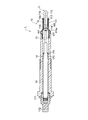
- FIG. 1 is a longitudinal sectional view of a ceramic heater type glow plug 1 for a diesel engine according to an embodiment of the present invention.
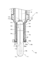
- FIG. 2 is a longitudinal sectional view of a ceramic heater type glow plug in which the vicinity of the ceramic assembly in FIG. 1 is enlarged.
- the glow plug 1 shown in FIGS. 1 and 2 includes a ceramic heater assembly 10, a housing 14, a lead bar 16, and the like.
- the cross section refers to a cut surface perpendicular to the longitudinal axis of the ceramic heater type glow plug 1
- the vertical cross section refers to a cut surface including the longitudinal axis of the ceramic heater type glow plug 1.
- the ceramic heater assembly 10 includes a ceramic heater 11, a metal outer cylinder (sheath) 12, a large-diameter lead portion 13, and the like.
- the ceramic heater 11 is a portion that is heated by energization, and a ceramic heating element 112 formed in a U shape is embedded in the ceramic heater 11 inside the ceramic insulating base 111 that constitutes the main body of the ceramic heater 11. .
- a positive electrode 114 and a negative electrode 115 are provided on both ends of the ceramic heating element 112 via metal leads 113, respectively.
- the negative electrode 115 is taken out on the outer peripheral surface of the ceramic insulating substrate 111, and a negative electrode side metallized portion 116 is formed on the outer peripheral surface of the ceramic insulating substrate 111 including the negative electrode 115.
- the outer cylinder 12 is formed of a conductive metal material.
- the outer cylinder 12 has an inner diameter that is large enough to allow the ceramic heater 11 to be inserted.
- the ceramic heater 11 and the outer cylinder 12 are joined by brazing by supplying a brazing material to the joint in a state where the negative electrode side metallized portion 116 of the ceramic heater 11 is inserted and fixed in the outer cylinder 12. . That is, the negative electrode side metallized portion 116 of the ceramic heater 11 is joined to the inner surface of the outer cylinder 12 by the brazing material and is electrically connected.
- the negative electrode side metallized part 116 is formed of, for example, a silver paste containing 30% by weight or less of copper (Cu) and 10% by weight or less of titanium (Ti) with respect to the total weight of the negative electrode side metallized part 116.
- the positive electrode 114 is taken out to the outer surface of the ceramic insulating base 111 on the rear end side opposite to the front end side where the ceramic heating element 112 is embedded.
- a positive side metallized portion 117 is formed on the rear end surface of the ceramic insulating base 111 including the positive side electrode 114.
- the positive side metallized portion 117 is joined to the tip surface 131 of the large diameter lead portion 13 by brazing or the like, and the positive side electrode 114 and the large diameter lead portion 13 are electrically connected.
- a chamfered portion 111 a is formed on the rear end surface of the ceramic insulating substrate 111.
- the distance between the ceramic insulating base 111 and the outer cylinder 12 can be increased around the joint between the ceramic insulating base 111 and the large-diameter lead portion 13. Therefore, in the case of brazing, the insulation between the brazing material and the outer cylinder 12 is enhanced, and the dielectric breakdown can be reduced.
- the outer cylinder 12 includes an element body 121, a metal layer 122 formed on the entire surface (inner surface and outer surface) of the element body 121, and a tip portion 125 on the ceramic heater side of the outer cylinder 12. And a coating layer 123 formed on the substrate.
- the thicknesses of the metal layer 122 and the coating layer 123 are shown relatively large in order to clearly describe the characteristics of the glow plug.
- the element body 121 is preferably an alloy mainly made of iron because it can withstand the brazing temperature. Particularly, since the heat resistance is high, an alloy mainly made of iron and Ni is more preferable, and stainless steel is more preferable. preferable. Further, among stainless steels, stainless steel alloys mainly composed of iron, Ni, and Cr are particularly preferable because of their high durability. In addition, it is preferable to form the element body 121 in a cylindrical shape from the viewpoint of uniformly brazing the ceramic heater and enhancing durability.
- the element body 121 has an enlarged cross-section in the middle of the axial direction, and a step-shaped enlarged diameter portion 127 is formed therein.
- this enlarged diameter portion 127 is a place where the brazing material is placed, the rear end side of the ceramic heater 11 to be inserted into the outer cylinder 12 than the negative side metallized portion 116 (opposite to the insertion end portion of the ceramic heater 11). In the direction end).
- the metal layer 122 is formed of a material having excellent conductivity and high wettability with the brazing material.
- An example of such a metal layer 122 is a metal plating layer.
- the metal plating layer include Ni (nickel) plating, and boron-based Ni plating is particularly preferable because of excellent durability.
- the thickness t 1 of the metal layer 122 is preferably 5 to 20 ⁇ m. Note that the metal layer 122 is not necessarily formed so as to cover the entire surface of the element body 121 evenly, and at least a portion in contact with the brazing material (installation of the brazing material) from the viewpoint of wettability with the brazing material. Or a connecting portion between the ceramic heater 11 and the outer cylinder 12).
- the coating layer 123 is formed of a material having low wettability with the brazing material (preferably one having lower wettability than the metal layer 122). Further, since the outer cylinder 12 is heated to a high temperature (about 800 to 900 ° C.) at the time of brazing, the coating layer 123 is preferably made of a thermally stable material.
- a thermally stable material is ceramics. Examples of ceramics include oxide-based, carbide-based, and nitride-based ceramics. Among these, oxide-based ceramics are preferable in terms of excellent heat resistance. Examples of oxide ceramics include silica, alumina, zirconia, titania, magnesia, and calcia. The above materials may be used alone or in combination.
- the coating layer 123 may be colored and may contain a pigment or a dye.
- the coating layer 123 is formed on the tip 125 of the outer cylinder 12 on the ceramic heater side. Specifically, the coating layer 123 only needs to be formed on at least one of the inner peripheral surface 125a, the end surface 125b, and the outer peripheral surface 125c in the distal end portion 125 of the outer cylinder 12. In FIG. 2, the coating layer 123 is formed on all surfaces of the inner peripheral surface 125a, the end surface 125b, and the outer peripheral surface 125c at the distal end portion 125 of the outer cylinder 12. For example, the coating layer 123 may be formed on the inner peripheral surface 125a of the distal end portion 125 of the outer cylinder 12 when the purpose is to reduce the amount of brazing material used.
- the length L along the axis of the outer cylinder 12 of the coating layer 123 is 0.5 to 1.0 mm. It is preferable that the coating layer 123 may be formed on the outer peripheral surface 125 c of the distal end portion 125 of the outer cylinder 12 when it is intended to be used as an identification mark of the ceramic heater type glow plug 1.
- the coating layer 123 is formed on the outer peripheral surface 125c of the distal end portion 125 of the outer cylinder 12 when it is intended to be used as an identification mark of the ceramic heater type glow plug 1.
- the length L along the axis of the outer cylinder 12 of the coating layer 123 is 0.5 to 1.0 mm.
- the film thickness t 2 of the coating layer 123 is preferably 2 to 15 ⁇ m.
- the large-diameter lead 13 is electrically connected to the positive electrode 114 of the ceramic heater 11.
- the large-diameter lead portion 13 flows at a high temperature and a large current (for example, 4 to 30 amperes) when the glow plug 1 is operated. Therefore, if the diameter is too small, for example, less than 1 mm, self-heating is added and the time is short. May oxidize. Therefore, the large-diameter lead portion 13 is formed as a lead rod having a relatively large diameter and having a cross-sectional area of 20% or more of the cross-sectional area of the ceramic insulating base 111, for example.
- the cross-sectional area of the large-diameter lead portion 13 is preferably 40% or less of the cross-sectional area of the ceramic insulating base 111, for example. Further, the length of the large-diameter lead portion 13 is preferably set to be twice or more the diameter of the large-diameter lead portion 13.
- the large-diameter lead portion 13 is made of a material having lower rigidity and higher electric conductivity than the lead rod 16 as an external connection terminal. Examples of such a material include copper (Cu), aluminum (Al), and alloys thereof. Alternatively, an iron alloy or cast iron having low rigidity and high electrical conductivity can be used.
- the large-diameter lead portion 13 may be subjected to nickel (Ni) plating or the like in order to improve heat resistance, and may be covered with silver (Ag) in order to improve oxidation resistance.
- the housing 14 is a fitting for attaching to a cylinder head of an engine (not shown), and accommodates the outer cylinder 12 and the large-diameter lead portion 13.
- the housing 14 is formed in a cylindrical shape, for example, and the ceramic heater assembly 10 configured as described above is fixed by brazing or the like.
- the other end of the outer cylinder 12 is fixed to the inside of the housing 14 by brazing or the like.
- the outer cylinder 12 is brazed to the inside of a metal tube or the like (not shown). It is also possible to fix the metal tube and the member constituting the housing main body, and form the housing 14 integrally.
- the lead bar 16 is accommodated in the housing 14 and fixed by a filler 173 and a seal ring 174 made of resin or low melting point glass filled between the housing 14. Further, the lead rod 16 is joined to the rear end portion of the large-diameter lead portion 13 by welding. The lead rod 16 is held by the insulator 171 on the rear end side of the housing 14, and the rear end portion is exposed to the outside of the housing 14 and connected to the round pin 172.
- a ceramic heater 11 and an outer cylinder 12 are prepared.
- the negative electrode side metallized portion 116 is formed on the outer peripheral surface thereof.
- a metal layer 122 and a coating layer 123 are formed on the outer cylinder 12.
- the metal layer 122 can be formed, for example, by performing metal plating or the like on the surface of the element body 121. As a plating method, a known method can be used.
- the coating layer 123 can be formed using, for example, a coating solution.
- a coating solution for example, a paint mainly composed of ceramics can be used.
- the coating material mainly composed of ceramics for example, KB coat, Fuji Gamma manufactured by Gamma Chemical Co., Ltd. are suitable.
- the application method include dip coating, spray coating, brush coating, flow coating, and transfer. Among these, dip coating is preferable from the viewpoint of ease of work.
- the concentration and viscosity of the coating solution are adjusted as appropriate according to the application method and the like. Further, the coating amount, depending on the film thickness t 2, etc. of the coating layer 123 to be formed may be appropriately adjusted, when increasing the thickness t 2 is that for recoating in several preferable. This is because if a large amount of coating solution is applied at once, the coating layer 123 after drying is cracked and easily peeled off.
- the ceramic heater 11 is inserted into the inner hole 120 of the outer cylinder 12.
- the ceramic heater 11 is inserted into the outer cylinder 12 until the enlarged diameter portion 127 of the outer cylinder 12 and the positive side metallized portion 117 of the ceramic heater 11 are in a predetermined positional relationship (see FIG. 3B).
- a brazing material 175 is placed on the enlarged diameter portion 127 of the outer cylinder 12. Further, the front end surface 131 of the large-diameter lead portion 13 is placed on the positive side metallized portion 117 of the ceramic heater 11. At this time, a brazing material 176 different from the brazing material 175 placed on the enlarged diameter portion 127 is placed between the positive electrode side metallized portion 117 and the large diameter lead portion 13. Thereafter, the assembly is heated to 800 to 900 ° C. in a state where the outer cylinder 12, the ceramic heater 11, and the large diameter lead portion 13 are temporarily assembled. Thereby, the ceramic heater 11 and the outer cylinder 12, the ceramic heater 11 and the large diameter lead part 13 are brazed simultaneously, respectively.
- the lead rod 16 and the large-diameter lead portion 13 are joined and fixed by welding (for example, spot welding).
- the housing 14 is lowered until the front end surface 141 of the housing 14 comes into contact with the rear end surface 129 of the protruding portion 128 of the outer cylinder 12. With the contact in this manner, the front end surface 141 of the housing 14 and the rear end surface 129 of the protruding portion 128 of the outer cylinder 12 are welded.
- the housing 14 and the outer cylinder 12 may be fixed by brazing the inner peripheral surface 142 of the housing 14 and the outer peripheral surface 12c of the outer cylinder 12.
- a seal ring 174 is inserted between the housing 14 and the lead bar 16.
- a filler 173 made of resin or low-melting glass is filled between the lead bar 16 and the housing 14.
- the brazing material can easily move on the inner peripheral surface 12a of the outer cylinder 12 during brazing.
- the brazing material can be satisfactorily supplied to the joint portion of the heater 11 with the negative electrode side metallized portion 116.
- the flow of the brazing material can be improved by using Ni (nickel) -B (boron) alloy plating as the metal layer 122. As a result, the durability and conductivity of the joint are improved.
- the brazing material can be prevented from spreading to the outer peripheral surface 12c of the outer cylinder 12 during brazing, and the outer cylinder 12 and the ceramic heater can be prevented.
- the brazing material can be stably supplied to the negative electrode side metallized portion 116 and the joint portion.
- the usage amount of the brazing material which is an expensive material can be controlled to an appropriate amount, an increase in manufacturing cost can be prevented.
- the coating layer 123 can be formed by a simple method while keeping the metal layer 122 once formed, and the spreading of the brazing material can be prevented by the coating layer 123. This eliminates the need for a conventional outer cylinder processing and cleaning step, and simplifies the process.
- the coating layer 123 is formed on the inner peripheral surface 125a of the distal end portion 125 of the outer cylinder 12, the amount of brazing material used can be minimized.
- the coating layer 123 is formed on the outer peripheral surface 125c of the distal end portion 125 of the outer cylinder 12, and the coating layer 123 has a color different from that of the outer cylinder 12 and the metal layer 122, thereby using the coating layer 123 as an identification mark. You can also. Since the appearance of the glow plug 1 is very similar, conventionally, there is a possibility that components are mistaken during assembly or the insertion direction is wrong. However, the coating layer 123 is replaced with the outer cylinder 12 and the metal layer 122. By using different colors, it is possible to prevent such erroneous assembly.
- the glow plug described above shows one aspect of the present invention and does not limit the present invention, and each embodiment can be arbitrarily changed within the scope of the present invention.
- the coating layer 123 is formed over the inner surface 125a, the end surface 125b, and the outer surface 125c of the tip portion of the outer cylinder 12, but it may be formed on any one surface.
Landscapes
- Engineering & Computer Science (AREA)
- Chemical & Material Sciences (AREA)
- Combustion & Propulsion (AREA)
- Mechanical Engineering (AREA)
- General Engineering & Computer Science (AREA)
- Resistance Heating (AREA)
Abstract
製造工程が従来よりも簡易化され、製造コストを低減すること。 セラミックスヒータ(11)と、一端部にセラミックスヒータがロウ材(175)によって接合され、他端部がハウジング(14)に固定された金属製の外筒(12)と、を備えたセラミックスヒータ型グロープラグ(1)であって、外筒は、その表面にロウ材に対する濡れ性を外筒の素材よりも向上させる金属層(122)を有し、外筒の一端部における金属層の表面には、ロウ材に対する濡れ性を金属層よりも低下させるコーティング層(123)が形成されている。
Description
本発明は、ディーゼルエンジンの始動補助用として使用されるセラミックスヒータ型グロープラグに関する。
ディーゼルエンジンの始動補助用として使用されるセラミックスヒータ型グロープラグは、セラミックスヒータの先端側の発熱部を外部に突出させた状態で、後端側を金属製の外筒内に保持させた構造を有している。かかるセラミックスヒータ型グロープラグは、外筒の後端側が、エンジンのシリンダヘッドへの取り付け金具である筒状ハウジングの先端部内に挿入されて固定されている。
セラミックスヒータ型グロープラグの製造コストは、セラミックス部分の長さに大きく依存する。そのため、セラミックス部分の長さを短くして製造コストを低減することを目的として、セラミックスヒータの一方の電極(負側電極)をセラミックス絶縁基体の外面に取り出して外筒の内面に電気的に接続するとともに、他方の電極(正側電極)を後端部から電極取出金具及び電極取出ロッドを介して外筒の外部に取り出すように構成したセラミックスヒータ型グロープラグが実用化されている。
このような構造を有するセラミックスヒータ型グロープラグでは、特に、セラミックスヒータの一方の電極(負側電極)と、外筒の内面との電気的な接続が重要となる。そのため、当該セラミックスヒータの一方の電極(負側電極)と、外筒の内面との接合には、ロウ材を用いた接合(ロウ付け)により接続することが多い(例えば、特許文献1参照)。
セラミックスヒータ型グロープラグの製造コストは、セラミックス部分の長さに大きく依存する。そのため、セラミックス部分の長さを短くして製造コストを低減することを目的として、セラミックスヒータの一方の電極(負側電極)をセラミックス絶縁基体の外面に取り出して外筒の内面に電気的に接続するとともに、他方の電極(正側電極)を後端部から電極取出金具及び電極取出ロッドを介して外筒の外部に取り出すように構成したセラミックスヒータ型グロープラグが実用化されている。
このような構造を有するセラミックスヒータ型グロープラグでは、特に、セラミックスヒータの一方の電極(負側電極)と、外筒の内面との電気的な接続が重要となる。そのため、当該セラミックスヒータの一方の電極(負側電極)と、外筒の内面との接合には、ロウ材を用いた接合(ロウ付け)により接続することが多い(例えば、特許文献1参照)。
ロウ付けは、セラミックスヒータの一方の電極(負側電極)と、外筒の内面との間の接合部近傍にロウ材を設置し、接合部近傍をロウ材の溶融温度以上に加熱して、表面張力により接合部にロウ材を供給することにより行われる。そのため、接合部にロウ材を良好に供給するためには、ロウ材と接触する外筒の内面が、ロウ材との濡れ性に優れた材質であることが好ましい。特許文献1においては、外筒の全面に、ロウ材に対する濡れ性が高いNi-B合金メッキによる金属層を形成している。
しかし、上述のように、金属層上でのロウ材の流動性はきわめて高いため、外筒の内部にロウ材を置いても、ロウ付け時にロウ材が外筒の内面を移動し、外筒の外側にまで広がり出てしまう問題があった。そこで、外筒の端面において、非メッキ部を形成し、ロウ付け時に、ロウ材が外筒の外面に広がり出ることを防止している。
しかし、上述のように、金属層上でのロウ材の流動性はきわめて高いため、外筒の内部にロウ材を置いても、ロウ付け時にロウ材が外筒の内面を移動し、外筒の外側にまで広がり出てしまう問題があった。そこで、外筒の端面において、非メッキ部を形成し、ロウ付け時に、ロウ材が外筒の外面に広がり出ることを防止している。
しかしながら、非メッキ部を形成するためには、一度形成した金属層を外筒の端面において機械的に除去する、あるいは金属層を形成する前に非メッキ部にマスキングを施す等の処理が必要であり、これらの処理は、製造工程が煩雑で、製造コストがかかるという問題があった。
そこで、本発明は、上記課題に鑑みてなされたものであり、製造工程が従来よりも簡易化され、製造コストを低減することができるセラミックスヒータ型グロープラグを提供することを目的とする。
上記課題を解決するため、本発明は、セラミックスヒータと、一端部に前記セラミックスヒータがロウ材によって接合され、他端部がハウジングに固定された金属製の外筒と、を備えたセラミックスヒータ型グロープラグであって、前記外筒は、その表面に前記ロウ材に対する濡れ性を前記外筒の素材よりも向上させる金属層を有し、前記外筒の一端部における前記金属層の表面には、前記ロウ材に対する濡れ性を前記金属層よりも低下させるコーティング層が形成されていることを特徴とする。
また、前記コーティング層は、少なくとも前記外筒の一端部の端面に形成されていることが好ましい。
また、前記コーティング層は、少なくとも前記外筒の一端部の内面に形成されていることが好ましい。
また、前記コーティング層は、少なくとも前記外筒の一端部の外面に形成されていることが好ましい。
また、前記コーティング層は、主としてセラミックスから構成されることが好ましい。
また、前記金属層は、Niメッキ層であることが好ましい。
また、前記コーティング層は、前記外筒の素材又は前記金属層とは異なる色を有していることが好ましい。
また、前記ロウ材は、銀ロウから構成されることが好ましい。
本発明は、上記のセラミックスヒータ型グロープラグの製造方法であって、前記外筒の素材表面に前記金属層を形成するステップと、前記外筒の一端部における前記金属層の表面に前記コーティング層を形成するステップと、前記セラミックスヒータを、前記一端部側から前記外筒に挿入するステップと、前記外筒の内側に前記ロウ材を設置するステップと、前記ロウ材を加熱して溶融し、前記セラミックスヒータと前記外筒との間に前記ロウ材を流動させて前記セラミックスヒータと前記外筒とを接合するステップと、を有することを特徴とする。
本発明によれば、セラミックスヒータ型グロープラグの製造工程が従来よりも簡易化され、製造コストを低減することができる。
本発明の好ましい実施形態について、図面を参照しながら説明する。なお、以下に示す実施形態は一つの例示であり、本発明の範囲において、種々の実施形態をとり得る。
図1は、本発明の実施形態にかかるディーゼルエンジン用のセラミックスヒータ型グロープラグ1の縦断面図である。図2は、図1において、セラミックスアセンブリ付近を拡大視したセラミックスヒータ型グロープラグの縦断面図である。図1、2に示すグロープラグ1は、セラミックスヒータアセンブリ10と、ハウジング14と、リード棒16等を備えている。以下、横断面とは、セラミックスヒータ型グロープラグ1の長手方向の軸線に垂直な切断面をいい、縦断面とは、セラミックスヒータ型グロープラグ1の長手方向の軸線を含む切断面をいう。
<セラミックスヒータアセンブリ>
セラミックスヒータアセンブリ10は、セラミックスヒータ11と、金属製の外筒(シース)12と、太径リード部13等を備えている。
セラミックスヒータアセンブリ10は、セラミックスヒータ11と、金属製の外筒(シース)12と、太径リード部13等を備えている。
(セラミックスヒータ)
セラミックスヒータ11は、通電により加熱される部位であり、セラミックスヒータ11には、その本体部を構成するセラミックス絶縁基体111の内部に、U字状に形成されたセラミックス発熱体112が埋設されている。このセラミックス発熱体112の両端側には、それぞれ金属リード113を介して正側電極114及び負側電極115が設けられている。負側電極115は、セラミックス絶縁基体111の外周面に取り出され、負側電極115を含むセラミックス絶縁基体111の外周面には、負極側メタライズ部116が形成されている。
セラミックスヒータ11は、通電により加熱される部位であり、セラミックスヒータ11には、その本体部を構成するセラミックス絶縁基体111の内部に、U字状に形成されたセラミックス発熱体112が埋設されている。このセラミックス発熱体112の両端側には、それぞれ金属リード113を介して正側電極114及び負側電極115が設けられている。負側電極115は、セラミックス絶縁基体111の外周面に取り出され、負側電極115を含むセラミックス絶縁基体111の外周面には、負極側メタライズ部116が形成されている。
セラミックスヒータ11のうち、少なくとも負極側メタライズ部116は、外筒12の一端側の内面に接合され、負側電極115は外筒12に電気的に接続されている。すなわち、外筒12は、導電性を有する金属材料から形成されている。外筒12は、その内径がセラミックスヒータ11を挿入できる程度の大きさに形成されており、セラミックスヒータ11を外筒12に挿入した際に、外筒12の内周面12aとセラミックスヒータ11の外周面118との間に僅かな隙間ができる程度に形成されている。
また、セラミックスヒータ11と外筒12との接合は、外筒12内にセラミックスヒータ11の負極側メタライズ部116を挿入、固定した状態で、接合部にロウ材を供給し、ロウ付けにより行われる。すなわち、セラミックスヒータ11の負極側メタライズ部116がロウ材によって外筒12の内面に接合され、電気的に接続される。負極側メタライズ部116は、例えば、負極側メタライズ部116全体の重量に対して30重量%以下の銅(Cu)と、10重量%以下のチタン(Ti)を含有する銀ペーストによって形成される。
正側電極114は、セラミックス発熱体112が埋設されている先端側とは反対の後端側においてセラミックス絶縁基体111の外面に取り出されている。正側電極114を含むセラミックス絶縁基体111の後端面には正極側メタライズ部117が形成されている。この正極側メタライズ部117はロウ付け等によって太径リード部13の先端面131に接合され、正側電極114と太径リード部13とが電気的に接続されている。
ここで、セラミックス絶縁基体111の後端面には、面取加工部111aが形成されている。これによって、セラミックス絶縁基体111と太径リード部13の接合部の周囲において、セラミックス絶縁基体111と外筒12との距離を稼ぐことができる。したがって、ロウ付けする場合において、ロウ材と外筒12との絶縁性が高められ、絶縁破壊を低減することができるようになっている。
ここで、セラミックス絶縁基体111の後端面には、面取加工部111aが形成されている。これによって、セラミックス絶縁基体111と太径リード部13の接合部の周囲において、セラミックス絶縁基体111と外筒12との距離を稼ぐことができる。したがって、ロウ付けする場合において、ロウ材と外筒12との絶縁性が高められ、絶縁破壊を低減することができるようになっている。
(外筒)
外筒12は、図1、2に示すように、素体121と、素体121の表面全域(内面及び外面)に形成された金属層122と、外筒12のセラミックスヒータ側の先端部125に形成されたコーティング層123と、を有している。なお、図1、2においては、グロープラグの特徴を明確に説明するため、金属層122及びコーティング層123の厚さを比較的大きく記載している。
外筒12は、図1、2に示すように、素体121と、素体121の表面全域(内面及び外面)に形成された金属層122と、外筒12のセラミックスヒータ側の先端部125に形成されたコーティング層123と、を有している。なお、図1、2においては、グロープラグの特徴を明確に説明するため、金属層122及びコーティング層123の厚さを比較的大きく記載している。
素体121は、ロウ付け温度に耐え得ることから、主に鉄からなる合金であることが好ましく、特に耐熱性が高いことから、主に鉄とNiからなる合金がより好ましく、中でもステンレスがさらに好ましい。さらに、ステンレスの中でも、耐久性が高いため、主に鉄とNiとCrからなるステンレス合金が特に好ましい。なお、セラミックヒーターのロウ付けを均一に行い、耐久性を高める観点から、素体121の形状は円筒状に形成することが好ましい。素体121は、その軸線方向途中で断面が拡径されており、内部に段状の拡径部127が形成されている。この拡径部127は、ロウ材を載置する場所となるため、外筒12に挿入されるセラミックスヒータ11の負極側メタライズ部116よりも後端側(セラミックスヒータ11の挿入端部とは逆方向の端部側)に形成しておく。
金属層122は、導電性に優れ、ロウ材との濡れ性が高い材料で形成されている。このような金属層122としては、例えば、金属メッキ層が挙げられる。金属メッキ層としては、例えば、Ni(ニッケル)メッキ等が挙げられ、特にホウ素系のNiメッキが耐久性に優れているのでより好ましい。
金属層122の膜厚t1は、5~20μmであることが好ましい。なお、金属層122は、必ずしも素体121の表面の全面を満遍なく覆うように形成されている必要はなく、ロウ材との濡れ性の観点から、少なくともロウ材と接触する箇所(ロウ材の設置部や、セラミックスヒータ11と外筒12との接続部)に形成されていればよい。
金属層122の膜厚t1は、5~20μmであることが好ましい。なお、金属層122は、必ずしも素体121の表面の全面を満遍なく覆うように形成されている必要はなく、ロウ材との濡れ性の観点から、少なくともロウ材と接触する箇所(ロウ材の設置部や、セラミックスヒータ11と外筒12との接続部)に形成されていればよい。
コーティング層123は、ロウ材との濡れ性が低い材料(金属層122よりも濡れ性が低いものが好ましい)で形成されている。また、外筒12は、ロウ付け時に高温(800~900℃程度)まで加熱されることから、コーティング層123は、熱的に安定な材料で構成されていることが好ましい。このような材料としては、例えば、セラミックスが挙げられる。セラミックスとしては、例えば酸化物系や炭化物系、窒化物系のセラミックスが挙げられる。中でも、酸化物系のセラミックスは耐熱性に優れる点で好ましい。また、酸化物系のセラミックスとしては、シリカ、アルミナ、ジルコニア、チタニア、マグネシア、およびカルシア等が挙げられる。上記の材料は、単独で用いてもよいし、組み合わせて用いてもよい。
コーティング層123は、着色されていてもよく、顔料や染料が含まれていてもよい。
コーティング層123は、着色されていてもよく、顔料や染料が含まれていてもよい。
コーティング層123は、外筒12のセラミックスヒータ側の先端部125に形成されている。具体的には、コーティング層123は、外筒12の先端部125における内周面125a、端面125bおよび外周面125cのうち少なくとも一つの面に形成されていればよい。図2においては、コーティング層123は、外筒12の先端部125における内周面125a、端面125bおよび外周面125cの全ての面に形成されている。
例えば、コーティング層123は、ロウ材の使用量を低減することを目的としている場合には、外筒12の先端部125の内周面125aに形成すればよい。コーティング層123が、外筒12の先端部125の内周面125aに形成されている場合には、コーティング層123の外筒12の軸線に沿った長さLは、0.5~1.0mmであることが好ましい。
また、コーティング層123は、セラミックスヒータ型グロープラグ1の識別標識として用いることを目的としている場合には、外筒12の先端部125の外周面125cに形成すればよい。コーティング層123が、外筒12の先端部125の外周面125cに形成されている場合には、コーティング層123の外筒12の軸線に沿った長さLは、0.5~1.0mmであることが好ましい。
コーティング層123の膜厚t2は、2~15μmであることが好ましい。
例えば、コーティング層123は、ロウ材の使用量を低減することを目的としている場合には、外筒12の先端部125の内周面125aに形成すればよい。コーティング層123が、外筒12の先端部125の内周面125aに形成されている場合には、コーティング層123の外筒12の軸線に沿った長さLは、0.5~1.0mmであることが好ましい。
また、コーティング層123は、セラミックスヒータ型グロープラグ1の識別標識として用いることを目的としている場合には、外筒12の先端部125の外周面125cに形成すればよい。コーティング層123が、外筒12の先端部125の外周面125cに形成されている場合には、コーティング層123の外筒12の軸線に沿った長さLは、0.5~1.0mmであることが好ましい。
コーティング層123の膜厚t2は、2~15μmであることが好ましい。
(太径リード部)
太径リード部13は、セラミックスヒータ11の正側電極114に電気的に接続されている。太径リード部13は、グロープラグ1の作動時に高温かつ大きな電流(例えば4~30アンペア)が流れることから、その直径が例えば1mm未満のように小さすぎると、自己発熱も加わって、短時間で酸化するおそれがある。そのため、太径リード部13は、例えば、セラミックス絶縁基体111の横断面積の20%以上の横断面積を有する、比較的太い直径を有するリード棒として形成されている。
一方で、太径リード部13の直径が大きすぎると、太径リード部13と外筒12との間の距離を十分に確保することができず、絶縁破壊を生じるおそれがある。よって、太径リード部13の横断面積は、例えば、セラミックス絶縁基体111の横断面積の40%以下であることが好ましい。また、太径リード部13の長さは、太径リード部13の直径の2倍以上の長さとすることが好ましい。
太径リード部13は、セラミックスヒータ11の正側電極114に電気的に接続されている。太径リード部13は、グロープラグ1の作動時に高温かつ大きな電流(例えば4~30アンペア)が流れることから、その直径が例えば1mm未満のように小さすぎると、自己発熱も加わって、短時間で酸化するおそれがある。そのため、太径リード部13は、例えば、セラミックス絶縁基体111の横断面積の20%以上の横断面積を有する、比較的太い直径を有するリード棒として形成されている。
一方で、太径リード部13の直径が大きすぎると、太径リード部13と外筒12との間の距離を十分に確保することができず、絶縁破壊を生じるおそれがある。よって、太径リード部13の横断面積は、例えば、セラミックス絶縁基体111の横断面積の40%以下であることが好ましい。また、太径リード部13の長さは、太径リード部13の直径の2倍以上の長さとすることが好ましい。
太径リード部13は、外部接続端子としてのリード棒16よりも剛性が低く、電気導電率が高い材料からなる。このような材料としては、例えば、銅(Cu)やアルミニウム(Al)、あるいはそれらの合金が挙げられる。あるいは、低剛性であり電気導電率が高い鉄合金や鋳鉄とすることもできる。
なお、太径リード部13には、耐熱性を改善するためにニッケル(Ni)メッキ等を施してもよく、耐酸化性を向上させるため、銀(Ag)により被覆してもよい。
なお、太径リード部13には、耐熱性を改善するためにニッケル(Ni)メッキ等を施してもよく、耐酸化性を向上させるため、銀(Ag)により被覆してもよい。
<ハウジング>
ハウジング14は、図示しないエンジンのシリンダヘッドへの取付金具であり、外筒12や太径リード部13を収容するものである。ハウジング14は、例えば、円筒状に形成され、上記のように構成されるセラミックスヒータアセンブリ10が、ロウ付け等により固定されている。図1の例では、ハウジング14の内部に外筒12の他端側がロウ付け等により固定されているが、その他の形態として、外筒12を金属管等(図示せず)の内部にロウ付け等によって固定し、その金属管とハウジング本体を構成する部材とを溶接して、一体のハウジング14として形成することもできる。
ハウジング14は、図示しないエンジンのシリンダヘッドへの取付金具であり、外筒12や太径リード部13を収容するものである。ハウジング14は、例えば、円筒状に形成され、上記のように構成されるセラミックスヒータアセンブリ10が、ロウ付け等により固定されている。図1の例では、ハウジング14の内部に外筒12の他端側がロウ付け等により固定されているが、その他の形態として、外筒12を金属管等(図示せず)の内部にロウ付け等によって固定し、その金属管とハウジング本体を構成する部材とを溶接して、一体のハウジング14として形成することもできる。
<リード棒>
リード棒16は、ハウジング14内に収容され、ハウジング14との間に充填された樹脂又は低融点ガラス等からなる充填剤173及びシールリング174によって固定されている。
さらに、リード棒16は、太径リード部13の後端部に溶接によって接合されている。
リード棒16は、ハウジング14の後端側でインシュレータ171に保持されるとともに、その後端部はハウジング14外部に露出して、ラウンドピン172と接続されている。
リード棒16は、ハウジング14内に収容され、ハウジング14との間に充填された樹脂又は低融点ガラス等からなる充填剤173及びシールリング174によって固定されている。
さらに、リード棒16は、太径リード部13の後端部に溶接によって接合されている。
リード棒16は、ハウジング14の後端側でインシュレータ171に保持されるとともに、その後端部はハウジング14外部に露出して、ラウンドピン172と接続されている。
<グロープラグの製造方法>
図3に基づいて、グロープラグ1の製造方法について説明する。
最初に、図3(a)に示すように、セラミックスヒータ11と外筒12とを準備する。
ここで、セラミックスヒータ11の一端(組み立てた際の後端側)近傍には、その外周面に負極側メタライズ部116を形成する。
また、外筒12には、金属層122およびコーティング層123を形成する。
金属層122は、例えば、素体121の表面に、金属メッキ等を施すことにより形成できる。メッキの方法は、公知の方法を用いることができる。
図3に基づいて、グロープラグ1の製造方法について説明する。
最初に、図3(a)に示すように、セラミックスヒータ11と外筒12とを準備する。
ここで、セラミックスヒータ11の一端(組み立てた際の後端側)近傍には、その外周面に負極側メタライズ部116を形成する。
また、外筒12には、金属層122およびコーティング層123を形成する。
金属層122は、例えば、素体121の表面に、金属メッキ等を施すことにより形成できる。メッキの方法は、公知の方法を用いることができる。
コーティング層123は、例えば、コーティング溶液を用いて形成することができる。コーティング溶液としては、例えばセラミックスを主成分とする塗料が挙げられる。セラミックスを主成分とする塗料としては、例えば、ガンマーケミカル株式会社製のKBコート、フジガンマー等が好適である。
塗布方法としては、例えば、ディップコーティング、スプレーコーティングや、ブラシ塗り、流し塗り、転写等がある。中でも、作業の容易性の観点から、ディップコーティングが好ましい。なお、塗布方法等に応じて、コーティング溶液の濃度や粘度は適宜調節する。
また、塗布量は、形成しようとするコーティング層123の膜厚t2等に応じて、適宜調整すればよく、膜厚t2を厚くする場合には、数回に分けて重ね塗りするのが好ましい。一度に多量のコーティング溶液を塗布すると、乾燥後のコーティング層123にひび割れが生じ、剥がれやすくなるためである。
塗布方法としては、例えば、ディップコーティング、スプレーコーティングや、ブラシ塗り、流し塗り、転写等がある。中でも、作業の容易性の観点から、ディップコーティングが好ましい。なお、塗布方法等に応じて、コーティング溶液の濃度や粘度は適宜調節する。
また、塗布量は、形成しようとするコーティング層123の膜厚t2等に応じて、適宜調整すればよく、膜厚t2を厚くする場合には、数回に分けて重ね塗りするのが好ましい。一度に多量のコーティング溶液を塗布すると、乾燥後のコーティング層123にひび割れが生じ、剥がれやすくなるためである。
次に、図3(a)に示すように、外筒12の内部孔120内にセラミックスヒータ11を挿入する。外筒12の拡径部127とセラミックスヒータ11の正極側メタライズ部117とが所定の位置関係(図3(b)参照)になるところまで、セラミックスヒータ11を外筒12内に挿入する。
次に、図3(b)に示すように、外筒12の拡径部127上にロウ材175を置く。また、太径リード部13の先端面131を、セラミックスヒータ11の正極側メタライズ部117上に置く。その際、正極側メタライズ部117と太径リード部13との間には、拡径部127上に置かれたロウ材175とは別のロウ材176を置く。
その後、外筒12、セラミックスヒータ11、太径リード部13を仮組みした状態で、このアッセンブリを800~900℃まで加熱する。これにより、セラミックスヒータ11及び外筒12、セラミックスヒータ11及び太径リード部13が、それぞれ同時にロウ付けされる。
その後、外筒12、セラミックスヒータ11、太径リード部13を仮組みした状態で、このアッセンブリを800~900℃まで加熱する。これにより、セラミックスヒータ11及び外筒12、セラミックスヒータ11及び太径リード部13が、それぞれ同時にロウ付けされる。
次に、図3(c)に示すように、リード棒16と太径リード部13とを溶接(例えばスポット溶接)よって接合し、固定する。
その後、図3(d)に示すように、ハウジング14の先端面141が外筒12の突出部128の後端面129に当接するまで、ハウジング14を下降させる。このように当接した状態で、ハウジング14の先端面141と外筒12の突出部128の後端面129とを溶接する。なお、ハウジング14の内周面142と外筒12の外周面12cとをロウ付けすることで、ハウジング14と外筒12とを固定してもよい。
また、図3(d)に示すように、ハウジング14とリード棒16との間に、シールリング174を挿入する。次いで、リード棒16とハウジング14との間に、樹脂又は低融点ガラス等からなる充填剤173を充填する。
また、図3(d)に示すように、ハウジング14とリード棒16との間に、シールリング174を挿入する。次いで、リード棒16とハウジング14との間に、樹脂又は低融点ガラス等からなる充填剤173を充填する。
最後に、図3(e)に示すように、ハウジング14の内部孔143の後端を、インシュレータ171によって塞ぐ。この際、インシュレータ171とハウジング14との間にはOリング177を設ける。
以上の工程をもって、グロープラグ1が組み立てられる。
以上の工程をもって、グロープラグ1が組み立てられる。
<実施形態の効果>
上記の構成によれば、外筒12は、その表面に金属層122を有しているので、ロウ付け時にロウ材が外筒12の内周面12aを移動しやすくなり、外筒12とセラミックスヒータ11の負極側メタライズ部116との接合部にロウ材を良好に供給できる。特に、金属層122として、Ni(ニッケル)-B(ホウ素)合金メッキを用いることにより、ロウ材の流れをよくすることができる。その結果、接合部の耐久性および導通性が向上する。外筒12は、セラミックスヒータ11側の先端部125にコーティング層123を有しているので、ロウ付け時にロウ材が外筒12の外周面12cへ広がることを防止でき、外筒12とセラミックスヒータ11の負極側メタライズ部116と接合部にロウ材を安定して供給できる。その結果、接合部に巣が発生することを防止でき、十分な接合強度と高い信頼性を確保できる。また、高価な材料であるロウ材の使用量を適量に制御できるため、製造コストの増大を防止できる。
上記の構成によれば、外筒12は、その表面に金属層122を有しているので、ロウ付け時にロウ材が外筒12の内周面12aを移動しやすくなり、外筒12とセラミックスヒータ11の負極側メタライズ部116との接合部にロウ材を良好に供給できる。特に、金属層122として、Ni(ニッケル)-B(ホウ素)合金メッキを用いることにより、ロウ材の流れをよくすることができる。その結果、接合部の耐久性および導通性が向上する。外筒12は、セラミックスヒータ11側の先端部125にコーティング層123を有しているので、ロウ付け時にロウ材が外筒12の外周面12cへ広がることを防止でき、外筒12とセラミックスヒータ11の負極側メタライズ部116と接合部にロウ材を安定して供給できる。その結果、接合部に巣が発生することを防止でき、十分な接合強度と高い信頼性を確保できる。また、高価な材料であるロウ材の使用量を適量に制御できるため、製造コストの増大を防止できる。
従来の方法では、ロウ材の広がりを防止するため外筒12の全面にメッキを形成した後、一部を機械的に研削することによりロウ材に対して濡れ性の低い非メッキ部を形成していたが、上記の構成によれば、一度形成した金属層122はそのままに、簡易な方法でコーティング層123を形成でき、このコーティング層123によりロウ材の広がりを防止できる。そのため、従来のような外筒の加工-洗浄工程が不要となり、工程が簡易化できる。
コーティング層123が、外筒12の先端部125の内周面125aに形成されていることにより、ロウ材の使用量を最小限にとどめることができる。
コーティング層123が、外筒12の先端部125の外周面125cに形成し、コーティング層123を、外筒12及び金属層122とは異なる色とすることにより、コーティング層123を識別標識として利用することもできる。グロープラグ1は、外観が酷似しているため、従来は、組み立ての際に部品を取り違える、または挿入方向を誤る等の可能性があったが、コーティング層123を外筒12及び金属層122とは異なる色とすることで、このような誤った組み立て等を防止することができる。
コーティング層123が、外筒12の先端部125の外周面125cに形成し、コーティング層123を、外筒12及び金属層122とは異なる色とすることにより、コーティング層123を識別標識として利用することもできる。グロープラグ1は、外観が酷似しているため、従来は、組み立ての際に部品を取り違える、または挿入方向を誤る等の可能性があったが、コーティング層123を外筒12及び金属層122とは異なる色とすることで、このような誤った組み立て等を防止することができる。
以上説明したグロープラグは、本発明の一態様を示すものであってこの発明を限定するものではなく、それぞれの実施形態は本発明の範囲内で任意に変更することが可能である。例えば、上記の実施形態において、コーティング層123は、外筒12の先端部の内面125a、端面125b、外面125cにわたって形成したが、いずれか一つの面に形成されていればよい。なお、コーティング層123によってグロープラグ1を識別するためには、外面125cにコーティング層123を形成しておくことが好ましい。
Claims (9)
- セラミックスヒータと、一端部に前記セラミックスヒータがロウ材によって接合され、他端部がハウジングに固定された金属製の外筒と、を備えたセラミックスヒータ型グロープラグであって、
前記外筒は、その表面に前記ロウ材に対する濡れ性を前記外筒の素材よりも向上させる金属層を有し、
前記外筒の一端部における前記金属層の表面には、前記ロウ材に対する濡れ性を前記金属層よりも低下させるコーティング層が形成されていることを特徴とするセラミックスヒータ型グロープラグ。 - 前記コーティング層は、少なくとも前記外筒の一端部の端面に形成されていることを特徴とする請求項1に記載のセラミックスヒータ型グロープラグ。
- 前記コーティング層は、少なくとも前記外筒の一端部の内面に形成されていることを特徴とする請求項1又は2に記載のセラミックスヒータ型グロープラグ。
- 前記コーティング層は、少なくとも前記外筒の一端部の外面に形成されていることを特徴とする請求項1から3までのいずれか一項に記載のセラミックスヒータ型グロープラグ。
- 前記コーティング層は、主としてセラミックスから構成されることを特徴とする請求項1から4までのいずれか一項に記載のセラミックスヒータ型グロープラグ。
- 前記金属層は、Niメッキ層であることを特徴とする請求項1から5までのいずれか一項に記載のセラミックスヒータ型グロープラグ。
- 前記コーティング層は、前記外筒の素材又は前記金属層とは異なる色を有していることを特徴とする請求項1から6までのいずれか一項に記載のセラミックスヒータ型グロープラグ。
- 前記ロウ材は、銀ロウから構成されることを特徴とする請求項1から7までのいずれか一項に記載のセラミックスヒータ型グロープラグ。
- 請求項1から8までのいずれか一項に記載のセラミックスヒータ型グロープラグの製造方法であって、
前記外筒の素材表面に前記金属層を形成するステップと、
前記外筒の一端部における前記金属層の表面に前記コーティング層を形成するステップと、
前記セラミックスヒータを、前記一端部側から前記外筒に挿入するステップと、
前記外筒の内側に前記ロウ材を設置するステップと、
前記ロウ材を加熱して溶融し、前記セラミックスヒータと前記外筒との間に前記ロウ材を流動させて前記セラミックスヒータと前記外筒とを接合するステップと、
を有することを特徴とするセラミックスヒータ型グロープラグの製造方法。
Priority Applications (1)
| Application Number | Priority Date | Filing Date | Title |
|---|---|---|---|
| JP2017507587A JP6395239B2 (ja) | 2015-03-23 | 2016-02-11 | セラミックスヒータ型グロープラグ |
Applications Claiming Priority (2)
| Application Number | Priority Date | Filing Date | Title |
|---|---|---|---|
| JP2015-059948 | 2015-03-23 | ||
| JP2015059948 | 2015-03-23 |
Publications (1)
| Publication Number | Publication Date |
|---|---|
| WO2016152302A1 true WO2016152302A1 (ja) | 2016-09-29 |
Family
ID=56977967
Family Applications (1)
| Application Number | Title | Priority Date | Filing Date |
|---|---|---|---|
| PCT/JP2016/054040 Ceased WO2016152302A1 (ja) | 2015-03-23 | 2016-02-11 | セラミックスヒータ型グロープラグ |
Country Status (2)
| Country | Link |
|---|---|
| JP (1) | JP6395239B2 (ja) |
| WO (1) | WO2016152302A1 (ja) |
Citations (3)
| Publication number | Priority date | Publication date | Assignee | Title |
|---|---|---|---|---|
| JPS6172932A (ja) * | 1984-09-14 | 1986-04-15 | Ngk Spark Plug Co Ltd | セラミツクグロ−プラグ |
| JP2005315447A (ja) * | 2004-04-27 | 2005-11-10 | Kyocera Corp | セラミックヒーターおよびグロープラグ |
| WO2014083913A1 (ja) * | 2012-11-29 | 2014-06-05 | ボッシュ株式会社 | セラミックスヒータ型グロープラグ及びその製造方法 |
Family Cites Families (1)
| Publication number | Priority date | Publication date | Assignee | Title |
|---|---|---|---|---|
| WO2014122958A1 (ja) * | 2013-02-08 | 2014-08-14 | ボッシュ株式会社 | 圧力センサ一体型グロープラグ及びその製造方法 |
-
2016
- 2016-02-11 JP JP2017507587A patent/JP6395239B2/ja active Active
- 2016-02-11 WO PCT/JP2016/054040 patent/WO2016152302A1/ja not_active Ceased
Patent Citations (3)
| Publication number | Priority date | Publication date | Assignee | Title |
|---|---|---|---|---|
| JPS6172932A (ja) * | 1984-09-14 | 1986-04-15 | Ngk Spark Plug Co Ltd | セラミツクグロ−プラグ |
| JP2005315447A (ja) * | 2004-04-27 | 2005-11-10 | Kyocera Corp | セラミックヒーターおよびグロープラグ |
| WO2014083913A1 (ja) * | 2012-11-29 | 2014-06-05 | ボッシュ株式会社 | セラミックスヒータ型グロープラグ及びその製造方法 |
Also Published As
| Publication number | Publication date |
|---|---|
| JP6395239B2 (ja) | 2018-09-26 |
| JPWO2016152302A1 (ja) | 2017-10-19 |
Similar Documents
| Publication | Publication Date | Title |
|---|---|---|
| JP7525569B2 (ja) | 熱交換ユニットおよびこれを備えた洗浄装置 | |
| JPH10205753A (ja) | セラミックグロープラグ | |
| JP6317469B2 (ja) | ヒータおよびこれを用いた流体加熱装置 | |
| EP3135998B1 (en) | Method for manufacturing ceramic-heater-type glow plug, and ceramic-heater-type glow plug | |
| JP5243498B2 (ja) | セラミックヒータ及びそれを備えたガスセンサ | |
| JP6005175B2 (ja) | セラミックスヒータ型グロープラグ及びその製造方法 | |
| JP6395239B2 (ja) | セラミックスヒータ型グロープラグ | |
| JP6245716B2 (ja) | セラミックスヒータ型グロープラグの製造方法及びセラミックスヒータ型グロープラグ | |
| JP2017182910A (ja) | ヒータ | |
| JP5868276B2 (ja) | セラミックヒータ、ガスセンサおよびセラミックヒータの製造方法 | |
| JP6313155B2 (ja) | ヒータ | |
| US10113744B2 (en) | Ceramic heater-type glow plug | |
| JP6270185B2 (ja) | セラミックスヒータ型グロープラグの製造方法及びセラミックスヒータ型グロープラグ | |
| JP2009293989A (ja) | セラミックヒータ及びガスセンサ | |
| JP6835946B2 (ja) | ヒータ | |
| JPWO2015146554A1 (ja) | セラミックスヒータ型グロープラグ | |
| JP6665495B2 (ja) | セラミックヒータ | |
| JP2009252389A (ja) | セラミックヒータ及びガスセンサ | |
| CN105744658B (zh) | 陶瓷加热器以及传感器 | |
| JP2018097985A (ja) | ヒーター | |
| JP2012068217A (ja) | ガスセンサ | |
| US20180112874A1 (en) | Glow plug | |
| JPWO2020175564A1 (ja) | 熱交換ユニットおよびこれを備えた洗浄装置 | |
| KR200442507Y1 (ko) | 고열형 전기 납땜 인두 |
Legal Events
| Date | Code | Title | Description |
|---|---|---|---|
| 121 | Ep: the epo has been informed by wipo that ep was designated in this application |
Ref document number: 16768205 Country of ref document: EP Kind code of ref document: A1 |
|
| ENP | Entry into the national phase |
Ref document number: 2017507587 Country of ref document: JP Kind code of ref document: A |
|
| NENP | Non-entry into the national phase |
Ref country code: DE |
|
| 122 | Ep: pct application non-entry in european phase |
Ref document number: 16768205 Country of ref document: EP Kind code of ref document: A1 |