WO2016152227A1 - チェンソーのブレーキ装置 - Google Patents
チェンソーのブレーキ装置 Download PDFInfo
- Publication number
- WO2016152227A1 WO2016152227A1 PCT/JP2016/051836 JP2016051836W WO2016152227A1 WO 2016152227 A1 WO2016152227 A1 WO 2016152227A1 JP 2016051836 W JP2016051836 W JP 2016051836W WO 2016152227 A1 WO2016152227 A1 WO 2016152227A1
- Authority
- WO
- WIPO (PCT)
- Prior art keywords
- belt
- lever
- link mechanism
- state
- brake
- Prior art date
- Legal status (The legal status is an assumption and is not a legal conclusion. Google has not performed a legal analysis and makes no representation as to the accuracy of the status listed.)
- Ceased
Links
Images





Classifications
-
- B—PERFORMING OPERATIONS; TRANSPORTING
- B27—WORKING OR PRESERVING WOOD OR SIMILAR MATERIAL; NAILING OR STAPLING MACHINES IN GENERAL
- B27B—SAWS FOR WOOD OR SIMILAR MATERIAL; COMPONENTS OR ACCESSORIES THEREFOR
- B27B17/00—Chain saws; Equipment therefor
- B27B17/08—Drives or gearings; Devices for swivelling or tilting the chain saw
- B27B17/083—Devices for arresting movement of the saw chain
Definitions
- the present invention relates to a chain saw brake device for stopping a saw chain.
- a chain saw is provided with a brake device that stops the saw chain when rebound (kickback) or the like occurs.
- brake devices have a drum that rotates integrally with a sprocket around which a saw chain is wound, and a brake belt that is wound around the outer peripheral surface of the drum.
- the brake device is configured to stop the saw chain by the brake belt tightening the drum when the kickback or the like occurs.
- a chain saw in which an auxiliary brake device is provided in addition to the brake device is also known.
- an auxiliary brake device for example, in the chain saw described in Patent Document 1, when the throttle lever lock is not operated, an end of the brake belt is pulled by a brake spring constituting the auxiliary brake device so that the brake belt tightens the drum. It is configured. In the chain saw having such a configuration, the stop state of the saw chain is not released unless the user operates the throttle lever lock, so that the operation of the saw chain unintended by the user can be prevented.
- an object of the present invention is to provide a chain saw brake device that can prevent the operation of the saw chain unintended by the user and can suppress an increase in the burden on the user.
- the saw chain is provided on a chain saw including a sprocket that is rotationally driven by a drive source, and a saw chain that is wound around the sprocket and driven via the sprocket, and stops the saw chain.
- a chain saw brake device is provided. The chain saw brake device is wound around the outer peripheral surface of a drum that rotates together with the sprocket, and the end of the drum is pulled to tighten the outer peripheral surface of the drum to stop the rotation of the drum and to rotate the drum.
- a brake belt that holds a stop state, a belt spring attached to a brake spring, and a belt tension state that pulls the end of the brake belt in conjunction with a trigger member; and a belt relaxation state that loosens the tension of the end of the brake belt
- a link mechanism that changes to a first position, and a displacement member that is displaced from the first position to the second position by operating an operation unit that is different from the trigger member.
- the displacement member When the displacement member is located at the first position, the displacement member prevents the link mechanism in the belt tension state from changing to the belt relaxed state, and returns from the second position to the first position. Sometimes it acts directly on the link mechanism in the belt relaxed state to change the link mechanism to the belt tensioned state.
- the saw chain is provided on a chain saw including a sprocket that is rotationally driven by an engine and a saw chain that is wound around the sprocket and driven via the sprocket, and stops the saw chain.
- a chain saw brake device is provided. The chain saw brake device is wound around the outer peripheral surface of the drum that rotates together with the sprocket, and the end of the drum is pulled to tighten the outer peripheral surface of the drum to stop the rotation of the drum and maintain the stopped state.
- the saw chain is not released from being stopped unless the operation portion is operated so that the displacement member is positioned at the second position. For this reason, the operation
- the user when releasing the stop state of the saw chain, the user only has to operate the operation unit against the force that biases the operation unit to the first position, and is directly applied to the spring force of the brake spring. It is not necessary to operate the operation unit against this. For this reason, an increase in the burden on the user is significantly suppressed as compared with the above-described conventional technology.
- FIG. 6B is a diagram illustrating the posture of the link mechanism when the hand guard is rotated forward from the normal position.
- (A) is a figure which shows the state of the said malfunction prevention mechanism when the lock-off lever of the said chain saw is not operated
- B) is a diagram illustrating a state of the malfunction prevention mechanism when the lock-off lever is operated. It is a figure for demonstrating operation
- FIG. 1 is a perspective view of a chain saw 1 to which the present invention is applied as viewed obliquely from the upper right rear side.
- a chain saw 1 includes a chain saw body 2 that houses an engine (not shown) as a drive source, a guide bar 3 that extends forward from the chain saw body 2, and a saw chain that is wound around the guide bar 3. 4, a top handle 5 extending in the front-rear direction above the chain saw body 2, a hand guard 6 disposed in front of the top handle 5, and extending from the left side surface of the top handle 5 to the left side surface of the chain saw body 2. And a side handle 7 that is substantially U-shaped in the lateral direction.
- the top handle 5 is provided with a throttle lever 8 provided on the lower side of the top handle 5, and a lock-off lever 9 and a state switching lever 10 provided on the upper side of the top handle 5.
- the throttle lever 8 is mainly operated to adjust the engine speed.
- the throttle lever 8 is always urged to the non-operation position shown in FIG. 1 and is operated so as to be pushed into the top handle 5 by the user.
- the lock-off lever 9 is provided to restrict the operation of the throttle lever 8. That is, the throttle lever 8 cannot be operated unless the lock-off lever 9 is operated.
- the lock-off lever 9 is always urged to the non-operation position shown in FIG. 1 like the throttle lever 8 and is operated to be pushed into the top handle 5 by the user.
- the state switching lever 10 is mainly operated to stop the engine or perform a choke operation.
- the state switching lever 10 can be operated by the user to each of a stop position where the engine is stopped, an operation position where the engine is operable, and a choke position where the choke operation is performed.
- the hand guard 6 functions as a brake lever that protects the user's hand and operates a brake device 20 (described later).
- the hand guard 6 is configured to be rotatable within a predetermined range from the normal position shown in FIG. 1 to a front side with a base 6a (described later) attached to the chain saw body 2 as a rotation center.
- the user usually holds the top handle 5 with the right hand, the side handle 7 with the left hand, and the saw chain 4 that travels on the outer periphery of the guide bar 3 while appropriately operating the throttle lever 8 as a cutting object such as wood.
- the object to be cut is cut by pressing.
- the lock-off lever 9 is pushed into the top handle 5 when the user grips the top handle 5 with the right hand, and the throttle lever 8 is pulled with the index finger of the user's right hand holding the top handle 5.
- the state switching lever 10 is pushed and pulled in the front-rear direction mainly with the thumb of the right hand of the user who holds the top handle 5.
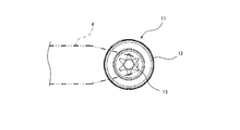
- FIG. 2 is a block diagram of the main part of the drive system of the chain saw 1.
- the drive system of the chain saw 1 includes a drive shaft (not shown) that is rotationally driven by the engine (drive source), a centrifugal clutch 11 attached to the drive shaft, and a clutch of the centrifugal clutch 11. And a sprocket 13 provided integrally with the drum (or brake drum) 12.
- the saw chain 4 is wound around the guide bar 3 (not shown in FIG. 2) and the sprocket 13.
- the centrifugal clutch 11 transmits the rotation of the drive shaft (the engine) to the clutch drum 12 when the rotation speed of the drive shaft (that is, the engine) reaches or exceeds a predetermined rotation speed.
- the clutch drum 12 and the sprocket 13 are rotationally driven, the saw chain 4 is driven via the sprocket 13, and the saw chain 4 travels on the outer periphery of the guide bar 3.
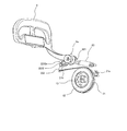
- FIG. 3 and 4 are views for explaining the configuration of the brake device 20 of the chain saw 1.
- FIG. FIG. 3 is an overall schematic configuration diagram of the brake device 20, and
- FIG. 4 is a view of a part of the brake device 20 as viewed from the side opposite to FIG.
- the brake device 20 has a brake belt 21, a link mechanism 22, and a tension coil spring (corresponding to the brake spring of the present invention) 23 acting on the link mechanism 22 as its basic configuration. And have.
- the brake belt 21 stops the saw chain 4 by stopping the rotation of the clutch drum 12.
- the brake belt 21 is wound around the outer peripheral surface of the clutch drum 12 and both ends thereof are drawn out from the clutch drum 12 in different directions.
- One end 21a of the brake belt 21 is fixed to the chain saw body 2 by a fixing tool 31 such as a fixing pin.
- the brake belt 21 tightens the outer peripheral surface of the clutch drum 12 when the other end 21b is pulled to stop the rotation of the clutch drum 12.
- the link mechanism 22 is connected to the hand guard 6 and the brake belt 21 and mainly operates in conjunction with the rotation of the hand guard 6 (corresponding to the trigger member of the present invention).
- the link mechanism 22 includes a belt tension state in which the brake belt 21 pulls the other end portion 21b of the brake belt 21 so that the outer peripheral surface of the clutch drum 12 is tightened, and a pulling of the other end portion 21b of the brake belt 21.
- the posture is changed between a relaxed (or released) belt relaxed state.
- the link mechanism 22 when the link mechanism 22 is in the belt tension state, the rotation stop state of the clutch drum 12 (that is, the stop state of the saw chain 4) is maintained, and when the link mechanism 22 is in the belt relaxed state, the clutch drum 12 rotates. (That is, the operation of the saw chain 4) is allowed.
- the link mechanism 22 includes a first link lever 221, a second link lever 222, and a connecting link member 223.
- first link lever 221 One end (including the vicinity) of the first link lever 221 is attached to the base 6 a of the hand guard 6 and operates (rotates) integrally with the hand guard 6.
- the other end of the first link lever 221 is located in front of the base 6 a of the hand guard 6.
- a shaft portion 221a is formed on the surface of the first link lever 221 opposite to the mounting surface of the one end portion of the first link lever 221 to the hand guard 6, and the shaft portion 221a is formed on the chain saw body 2. Is rotatably supported by a bearing portion (not shown).
- the second link lever 222 has a shaft portion 222a at an intermediate portion thereof, and the shaft portion 222a is rotatably supported by a bearing portion (not shown) provided in the chain saw body 2.
- One end of the second link lever 222 (including the vicinity) is attached to one end of the tension coil spring 23, and the other end (near the vicinity) of the second link lever 222 sandwiching the shaft portion 222a (that is, the rotation center).
- the other end 21b of the brake belt 21 is fixed (latched).
- the other end of the tension coil spring 23 is fixed to a fixing part 32 such as a boss formed on the chain saw body 2. Accordingly, the tension coil spring 23 applies an urging force (spring force) for rotating the second link lever 222 to the second link lever 222.
- the connecting link member 223 connects the first link lever 221 and the second link lever 222 so as to be rotatable. Specifically, the connecting link member 223 connects the other end portion of the first link lever 221 and a predetermined portion closer to the one end portion than the shaft portion 222a (rotation center) of the second link lever 222. ing.
- the connection link member 223 includes a first connection plate 2231 and a second connection plate 2232, and the other end of the first link lever 221 and the second connection plate 2232 are interposed between the plates 2231 and 2232.
- the predetermined part of the two link lever 222 is arranged at a predetermined interval.
- the 2nd connection plate 2232 has the protrusion part 2232a which protrudes ahead rather than the 2nd link lever 222, when the link mechanism 22 exists in the state shown in FIG. 3 (refer FIG. 4).
- FIG. 5 is a diagram for explaining the basic operation (change in posture) of the link mechanism 22.
- FIG. 5A is a view showing the posture of the link mechanism 22 when the hand guard 6 as the trigger member is in the normal position
- FIG. 5B is a diagram in which the hand guard 6 moves forward from the normal position. It is a figure which shows the attitude
- the link mechanism 22 is held in a locked state in which the posture is not changed by the spring force of the tension coil spring 23.
- the other end portion of the second link lever 222 to which the other end portion 21b of the brake belt 21 is fixed is in a position closest to the clutch drum 12 within the movable range, and the link mechanism 22 It is in a state.
- the first link lever 221 is rotated in the arrow B direction accordingly. (See FIG. 5B). Then, the link mechanism 22 is released from the locked state, and the first link lever 221 is further rotated in the direction of arrow B by the spring force of the tension coil spring 23 as shown in FIG.
- the two link lever 222 rotates in the direction of arrow C. As a result, the other end of the second link lever 222 moves away from the clutch drum 12 and pulls the other end 21b of the brake belt 21, and the link mechanism 22 changes from the belt relaxed state to the belt tensioned state. (Changes). At this time, the hand guard 6 rotates to the front rotation position on the frontmost side of the movable range.
- the brake device 20 stops the saw chain 4 and stops the saw chain 4 when the kickback occurs or when the user operates the hand guard 6 forward by the basic configuration and operation described above. It is possible to hold.
- the brake device 20 further includes a malfunction prevention mechanism 24 for the saw chain 4 in order to more reliably prevent the operation of the saw chain 4 unintended by the user.
- This malfunction prevention mechanism 24 is configured to keep the link mechanism 22 in the belt tension state whenever the lock-off lever 9 (corresponding to the operation unit of the present invention) is not operated.
- the malfunction prevention mechanism 24 will be described.
- the malfunction prevention mechanism 24 is disposed in the vicinity of the first rotation lever 241 disposed near the link mechanism 22, the compression coil spring 242 acting on the first rotation lever 241, and the lock-off lever 9. It includes a second rotation lever 243 and a connecting cable 244 that connects the first rotation lever 241 and the second rotation lever 243 (see FIG. 3).
- the first rotation lever 241 has a shaft portion 241 at an intermediate portion thereof, and the shaft portion 241a is rotatably supported by a bearing portion (not shown) provided in the chain saw body 2.
- the compression coil spring 242 is attached to a mounting portion (not shown) formed in the chain saw body 2 and constantly biases one end portion side of the first rotating lever 241 (near the end portion far from the link mechanism 22). is doing.
- the second rotation lever 243 is rotatably supported by a support shaft (not shown) formed in the top handle 5 through an insertion hole 243a formed in the intermediate portion.
- One end (including the vicinity) of the second turning lever 243 is in contact with or connected to the lower part of the lock-off lever 9, and the second turning lever 243 is interlocked with the pushing operation of the lock-off lever 9. It rotates around the support shaft.
- connection cable 244 connects the one end of the first rotation lever 241 and the other end (including the vicinity) of the second rotation lever 243.
- a portion of the connection cable 244 on the first rotation lever 241 side is disposed inside the compression coil spring 242. That is, the connecting cable 244 extends from the other end portion of the second rotating lever 243 in the top handle 5 and the chain saw body 2 and passes through the inside of the compression coil spring 242 to pass the one end of the first rotating lever 241.
- the connecting cable 244 is configured by, for example, a Bowden cable, and the one end of the first rotating lever 241 is mainly used as a tensile force generated by the rotation of the second rotating lever 243, in other words, the pushing operation force of the lock-off lever 9. Communicate to the department.
- FIG. 6 is a diagram for explaining the operation of the malfunction prevention mechanism 24.
- 6A is a diagram showing a state of the malfunction prevention mechanism 24 when the lock-off lever 9 is not pushed in (that is, when the lock-off lever 9 is in the non-operation position).
- B) is a diagram illustrating a state of the malfunction prevention mechanism 24 when the lock-off lever 9 is pushed in.
- the other end of the first rotating lever 241 that is, the one end biased by the compression coil spring 242 is The opposite end (including the vicinity) across the center of rotation is located in the operation locus of the link mechanism 22 (shown by an imaginary line).
- the other end portion of the first rotation lever 241 is positioned at the first position on the movement locus of the connecting portion of the link mechanism 22 between the first link lever 221 and the connecting link member 223 or a portion in the vicinity thereof. To position.
- the second turning lever 243 turns in the direction of arrow D to pull the connecting cable 244, and the pulling force is the first time. It is transmitted to the one end of the moving lever 241.
- the first rotation lever 241 rotates in the direction of arrow E against the spring force of the compression coil spring 242.
- the other end portion of the first rotation lever 241 is positioned outside the operation locus of the link mechanism 22, more specifically, the connection portion between the first link lever 221 and the connection link member 223 in the link mechanism 22. Alternatively, it is displaced to the second position retracted from the movement locus of the part in the vicinity thereof.
- the lock-off lever 9 When the push-in operation of the lock-off lever 9 is released, the lock-off lever 9 returns to the non-operation position, and accordingly, the malfunction prevention mechanism 24 is changed from the state shown in FIG. Return to the state shown in A). That is, the other end portion of the first rotation lever 241 returns from the second position outside the operation locus of the link mechanism 22 to the first position within the operation locus of the link mechanism 22. Accordingly, the first rotation lever 241 corresponds to the “displacement member” of the present invention.
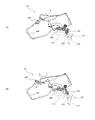
- FIG. 7 is a view for explaining the operation of the brake device 20 when the user releases his / her hand from the top handle 5 while using the chain saw 1.
- FIG. 7A shows a state of the brake device 20 when the chain saw 1 is in use.
- the lock-off lever 9 is pushed in by the user, and the other end portion of the first rotation lever 241 of the malfunction prevention mechanism 24 is in the second position outside the operation locus of the link mechanism 22. It is in. Further, the hand guard 6 is in the normal position, and the link mechanism 22 is in the belt relaxed state. Therefore, the clutch drum 12 can rotate, and the saw chain 4 operates according to the operation of the throttle lever 8 by the user.
- the lock-off lever 9 returns from the operated position to the non-operated position as shown in FIG.
- the second rotation lever 243 of the malfunction prevention mechanism 24 rotates in the direction of arrow F.
- the tensile force with respect to the connection cable 244 is released, and the first rotation lever 241 rotates in the arrow G direction by the spring force of the compression coil spring 242.
- the other end of the first rotation lever 241 is displaced (returned) from the second position outside the operation locus of the link mechanism 22 to the first position within the operation locus of the link mechanism 22.
- the other end portion of the first rotation lever 241 pushes the connecting portion between the first link lever 221 and the connecting link member 223 of the link mechanism 22 or the portion in the vicinity thereof, thereby the posture of the link mechanism 22. To change. As a result, the link mechanism 22 is released from the locked state.
- the link mechanism 22 When released from the locked state, the link mechanism 22 further changes the posture by the spring force of the tension coil spring 23. That is, as shown in FIG. 7C, the second link lever 222 rotates in the direction of the arrow C and the other end of the second link lever 222 moves away from the clutch drum 12, The link mechanism 22 is in the belt tension state. Therefore, the clutch drum 12 and the saw chain 4 are immediately stopped and the stopped state of the saw chain 4 is maintained. As the link mechanism 22 changes from the belt relaxed state to the belt tensioned state, the hand guard 6 moves from the normal position to the forward rotation position as in the case of the kickback.
- FIG. 8 is a diagram for explaining a procedure for releasing the stop state of the saw chain 4 by the brake device 20 (however, the hand guard 6 is not shown).
- FIG. 8A shows a state of the brake device 20 when the saw chain 4 is kept stopped (the same state as FIG. 7C).
- the hand guard 6 is in the forward rotation position.
- the lock-off lever 9 is in the non-operation position, and the other end portion of the first rotation lever 241 of the malfunction prevention mechanism 24 is located at the first position in the operation locus of the link mechanism 22. .
- the connection between the first link lever 221 and the connection link member 223 as shown in FIG. Or the portion in the vicinity thereof cannot contact the other end of the first rotation lever 241 and move any further.
- the user cannot change the posture of the link mechanism 22 to the locked state, and when the user releases the hand guard 6, the link mechanism 22 is in the belt tension state by the spring force of the tension coil spring 23. End up. Therefore, the user cannot change the link mechanism 22 from the belt tension state to the belt relaxation state, that is, release the stop state of the saw chain 4 simply by operating the hand guard 6.
- the first turning lever 241 turns in the direction of arrow E as shown in FIG. 8C, and the other end of the first turning lever 241 is turned on.
- the part moves to the second position outside the operation locus of the link mechanism 22. Therefore, the movement of the connecting portion between the first link lever 221 and the connecting link member 223 or the portion in the vicinity thereof is not blocked by the other end portion of the first rotating lever 241. Therefore, the user can return the hand guard 6 from the forward rotation position to the normal position, whereby the link mechanism 22 is in the belt relaxed state and the stop state of the saw chain 4 is released.
- the link mechanism 22 moves from the belt relaxed state to the belt tensioned state. To change. For this reason, for example, when the kickback occurs, the brake belt 21 quickly tightens the outer peripheral surface of the clutch drum 12 to stop the rotation of the clutch drum 12 and the sprocket 13, and the saw chain 4 stops accordingly. Is done.
- the brake device 20 (the malfunction prevention mechanism 24 thereof) has a first rotation lever 241, and the first rotation lever 241 is formed by the compression coil spring 242 in the operation locus of the link mechanism 22.
- the lock-off lever 9 When the lock-off lever 9 is operated, it is displaced from the first position to the second position outside the movement locus of the link mechanism 22 while being biased to the first position.
- the first rotation lever 241 When the first rotation lever 241 is located at the first position, the link mechanism 22 in the belt tension state is prevented from changing to the belt loose state, and the operation of the lock-off lever 9 is released. Then, when returning from the second position to the first position, the link mechanism 22 that directly acts on the link mechanism 22 is changed to the belt tension state.
- the brake device 20 in the present embodiment is configured such that the stop state of the saw chain 4 cannot be released unless the user operates the lock-off lever 9. For this reason, the operation
- the user pushes the lock-off lever 9 against the spring force of the compression coil spring 242 that biases the first rotation lever 241 to the first position. There is no need to operate directly against the spring force of the tension coil spring 23 as a brake spring. For this reason, the operation force for releasing the stop state of the saw chain 4, that is, the operation force of the lock-off lever 9 may be relatively small.
- the chain saw 1 uses the engine as a drive source.
- the present invention is not limited to this, and the present invention can also be applied to a chain saw using an electric motor or the like as a drive source.
- the first rotation lever 241 is interlocked with the operation of the lock-off lever 9 and the first position within the operation locus of the link mechanism 22 and the second position outside the operation locus of the link mechanism 22. It is comprised so that it may displace. However, it is not limited to this.
- the first rotation lever 241 may be displaced to the first position and the second position in conjunction with an operation unit other than the hand guard 6 that can be operated by the user of the chain saw 1.
- the first rotation lever 241 may be configured to be displaced between the first position and the second position in conjunction with the operation of the throttle lever 8.
- the first rotation lever 241 is configured to be displaced from the first position to the second position when the throttle lever 8 is operated. Even if it does in this way, the effect similar to the above-mentioned embodiment is acquired.
- a rotation lever that is displaced in conjunction with the operation of the state switching lever 10 may be provided instead of the first rotation lever 241.
- a configuration example of the brake device 50 in this case will be described with reference to FIGS. 9 and 10. 9 and 10, the same elements as those of the brake device 20 according to the above-described embodiment are denoted by the same reference numerals, and the description thereof is omitted.
- FIG. 9 is an overall schematic configuration diagram of a brake device 50 having a configuration different from that of the brake device 20 described above.
- the brake device 50 includes a brake belt 21, a link mechanism 22, a tension coil spring (brake spring) 23, and a malfunction prevention mechanism 54.
- the malfunction prevention mechanism 54 mainly stops the link mechanism 22 in the belt tension state (that is, the saw chain 4 is stopped) during the choke operation in order to more effectively prevent the operation of the saw chain 4 unintended by the user when starting the engine. State).
- the rotational speed of the engine is higher than when the engine is normally started. Therefore, the centrifugal clutch 11 may transmit the rotation of the drive shaft (the engine) to the clutch drum 12. Therefore, the malfunction prevention mechanism 54 mainly prevents the operation of the saw chain 4 in such a case.
- the malfunction prevention mechanism 54 includes a rotation lever 541 disposed in the vicinity of the link mechanism 22 and a connection cable 542 for connecting the state switching lever 10 and the rotation lever 541.
- the rotation lever 541 is rotatably supported by a support shaft (not shown) formed in the chain saw body 2 through an insertion hole 541a formed in the intermediate portion.
- the connection cable 542 connects a predetermined portion of the state switching lever 10 and one end (including the vicinity) of the rotation lever 541.
- the connection cable 542 is configured by, for example, a Bowden cable, like the connection cable 242 in the above-described embodiment, and transmits the tensile force generated by the operation of the state switching lever 10 to the one end of the rotation lever 541.
- the state switching lever 10 is connected to a choke operation member 15 of a carburetor (carburetor) 14 disposed near the rear end of the top handle 5 via a choke rod 543 extending in the front-rear direction in the top handle 5.
- the choke operation member 15 is a member for closing the choke valve (not shown) built in the carburetor 14 and constantly energized in the opening direction.
- FIG. 10 is a view for explaining the operation of the malfunction prevention mechanism 54, and is a view of the main configuration of the brake device 50 as viewed from the opposite side to FIG.
- FIG. 10 (A) shows a state of the brake device 50 when the state switching lever 10 is not operated, that is, when the state switching lever 10 is in the driving position.
- the hand guard 6 is in the normal position, and the link mechanism 22 is held in the locked state and is in the belt relaxed state. Therefore, the clutch drum 12 can rotate, and the saw chain 4 also operates as the clutch drum 12 rotates.
- the other end portion of the rotation lever 541 constituting the malfunction prevention mechanism 54 that is, the end portion (including the vicinity) opposite to the one end portion to which the connection cable 542 is connected, sandwiching the rotation center, It is in the initial position where it does not act on the link mechanism 22.
- the other end portion of the rotation lever 541 is located at a position close to the protruding portion 2232a of the second connecting plate 2232 constituting the connecting link member 223 of the link mechanism 22 (here, below the protruding portion 2232a). is there.
- the rotation lever 541 is configured such that the choke operating member 15, the choke rod 543, the state switching lever 10, and the connection cable 542 are urged by a biasing member (for example, a torsion coil spring) that constantly biases the choke valve in the valve opening direction. It can also be said that it is biased to the initial position that does not indirectly act on the link mechanism 22 via.
- the link mechanism 22 is released from the locked state, and the link mechanism 22 enters the belt tension state by the spring force of the tension coil spring 23. Therefore, even when the engine speed is unexpectedly increased and the centrifugal clutch 11 transmits the rotation of the drive shaft (the engine) to the clutch drum 12 when the engine is started, the clutch drum 12 rotates. The operation of the saw chain 4 is prevented. In addition, when the attitude
- the state switching lever 10 may be configured to return to the driving position when the user operates the throttle lever 8.
- the brake device 50 having such a malfunction prevention mechanism 54 According to the brake device 50 having such a malfunction prevention mechanism 54, the operation of the saw chain 4 unintended by the user, particularly when the engine is started, is prevented. In addition, an increase in the burden on the user (operating force) when operating the state switching lever 10 can be small.
- compression coil spring 243 ... second rotation Lever, 244 ... Connecting cable, 50 ... Brake device, 54 ... Malfunction prevention mechanism, 541 ... Rotating lever, 542 ... Binding cables, 2231 ... first connecting plate, 2232 ... second connecting portion rates, 2232A ... projecting portion
Landscapes
- Life Sciences & Earth Sciences (AREA)
- Engineering & Computer Science (AREA)
- Mechanical Engineering (AREA)
- Wood Science & Technology (AREA)
- Forests & Forestry (AREA)
- Sawing (AREA)
- Braking Arrangements (AREA)
Abstract
使用者の意図しないソーチェーンの動作を防止でき、かつ、使用者の負担の増加を抑制することのできるチェンソーのブレーキ装置を提供する。チェンソーのブレーキ装置(20)は、クラッチドラム(12)の外周面に巻回されたブレーキベルト(21)と、ブレーキベルト(21)の端部を引っ張るベルト引張状態とブレーキベルト(21)の前記端部の引っ張りを緩めたベルト弛緩状態とに変化するリンク機構(22)と、第1位置に付勢され、ロックオフレバー(9)が操作されることによって前記第1位置から第2位置へと変位する第1回動レバー(241)と、を有する。第1回動レバー(241)は、前記第1位置にあるときにリンク機構(22)の前記ベルト引張状態から前記ベルト弛緩状態への変化を阻止し、前記第2位置から前記第1位置に戻るときにリンク機構(22)を前記ベルト引張状態へと変化させる。
Description
本発明は、ソーチェーンを停止させるチェンソーのブレーキ装置に関する。
一般に、チェンソーには、跳ね返り(キックバック)などが発生したときにソーチェーンを停止させるブレーキ装置が設けられている。このようなブレーキ装置の多くは、ソーチェーンが巻き掛けられたスプロケットと一体に回転するドラムと、当該ドラムの外周面に巻回されたブレーキベルトと、を有する。そして、前記ブレーキ装置は、前記キックバックなどが発生したときに前記ブレーキベルトが前記ドラムを締め付けることによって前記ソーチェーンを停止させるように構成されている。
また、前記ブレーキ装置に加えて補助ブレーキ装置が設けられたチェンソーも知られている。例えば、特許文献1に記載のチェンソーは、スロットルレバーロックが操作されていないときには、前記補助ブレーキ装置を構成するブレーキばねによって前記ブレーキベルトの端部を引っ張って前記ブレーキベルトが前記ドラムを締め付けるように構成されている。このような構成のチェンソーでは、使用者が前記スロットルレバーロックを操作しなければ前記ソーチェーンの停止状態が解除されないので、使用者の意図しない前記ソーチェーンの動作が防止され得る。
しかし、特許文献1に記載のチェンソーにおいて、前記ソーチェーンの停止状態を解除するためには、前記スロットルレバーロックが前記ブレーキばねのばね力に抗して操作される必要がある。このため、前記ソーチェーンの停止状態を解除する際の前記スロットルレバーロックの操作力が大きくならざるを得ず、使用者の負担が大きい。一方、使用者の負担を軽減するために前記ブレーキばねのばね力を小さくすると、前記補助ブレーキ装置のブレーキ力が不足してしまうおそれがある。
そこで、本発明は、使用者の意図しない前記ソーチェーンの動作を防止でき、かつ、使用者の負担の増加を抑制することのできるチェンソーのブレーキ装置を提供することを目的とする。
本発明の一側面によると、駆動源によって回転駆動されるスプロケットと、前記スプロケットに巻き掛けられて前記スプロケットを介して駆動されるソーチェーンと、を含むチェンソーに設けられ、前記ソーチェーンを停止させるチェンソーのブレーキ装置が提供される。このチェンソーのブレーキ装置は、前記スプロケットと共に回転するドラムの外周面に巻回され、その端部が引っ張られることによって前記ドラムの前記外周面を締め付けて前記ドラムの回転を停止させると共に前記ドラムの回転停止状態を保持するブレーキベルトと、ブレーキばねが取り付けられ、トリガー部材に連動して前記ブレーキベルトの前記端部を引っ張るベルト引張状態と前記ブレーキベルトの前記端部の引っ張りを緩めたベルト弛緩状態とに変化するリンク機構と、第1位置に付勢され、前記トリガー部材とは別の操作部が操作されることによって前記第1位置から第2位置へと変位する変位部材と、を有する。そして、前記変位部材は、前記第1位置に位置しているときに前記ベルト引張状態にある前記リンク機構の前記ベルト弛緩状態への変化を阻止し、前記第2位置から前記第1位置に戻るときに前記ベルト弛緩状態にある前記リンク機構に直接作用して前記リンク機構を前記ベルト引張状態へと変化させる。
本発明の他の側面によると、エンジンによって回転駆動されるスプロケットと、前記スプロケットに巻き掛けられて前記スプロケットを介して駆動されるソーチェーンと、を含むチェンソーに設けられ、前記ソーチェーンを停止させるチェンソーのブレーキ装置が提供される。このチェンソーのブレーキ装置は、前記スプロケットと共に回転するドラムの外周面に巻回され、その端部が引っ張られることによって前記ドラムの前記外周面を締め付けて前記ドラムの回転を停止させると共に停止状態を保持するブレーキベルトと、ブレーキばねが取り付けられ、トリガー部材に連動して前記ブレーキベルトの前記端部を引っ張るベルト引張状態と前記ブレーキベルトの前記端部の引っ張りを緩めたベルト弛緩状態とに変化するリンク機構と、前記エンジンの始動時にチョーク操作が行われることによって変位すると共に前記ベルト弛緩状態にある前記リンク機構に直接作用して前記リンク機構を前記ベルト引張状態に変化させる変位部材と、を有する。
前者の前記チェンソーのブレーキ装置においては、前記変位部材が前記第2位置に位置するように前記操作部が操作されていなければ、前記ソーチェーンの停止状態が解除されない。このため、使用者の意図しない前記ソーチェーンの動作が効果的に防止され得る。また、前記ソーチェーンの停止状態を解除する際、使用者は前記操作部を前記第1位置に付勢する力に抗して前記操作部を操作すればよく、前記ブレーキばねのばね力に直接抗して前記操作部を操作する必要はない。このため、上述の従来技術に比べて使用者の負担の増加が大幅に抑制される。
また、後者の前記チェンソーのブレーキ装置においては、前記エンジンの始動時に前記チョーク操作が行われると、前記リンク機構が前記ベルト引張状態となって前記ソーチェーンが停止状態となる。このため、エンジン始動時における使用者の意図しない前記ソーチェーンの動作が防止される。また、前記チョーク操作及びその解除は、前記ブレーキばねのばね力に直接抗して行う必要がないので、使用者の負担の増加も抑制される。
以下、添付図面を参照しつつ本発明の実施形態について説明する。図1は、本発明が適用されたチェンソー1を右斜め後ろ上方から見た斜視図である。図1に示すように、チェンソー1は、駆動源としてのエンジン(図示省略)を収容したチェンソー本体2と、チェンソー本体2から前方に延びるガイドバー3と、ガイドバー3に巻き掛けられたソーチェーン4と、チェンソー本体2の上方において前後方向に延びるトップハンドル5と、トップハンドル5の前方に配設されたハンドガード6と、トップハンドル5の左側面からチェンソー本体2の左側面まで延在する横向き略U字状のサイドハンドル7と、を有する。
トップハンドル5には、トップハンドル5の下側に設けられたスロットルレバー8と、トップハンドル5の上側に設けられたロックオフレバー9及び状態切替レバー10と、が設けられている。
スロットルレバー8は、主に前記エンジンの回転数を調整するために操作される。スロットルレバー8は、図1に示す非操作位置に常時付勢されており、使用者によってトップハンドル5内に押し込むように操作される。ロックオフレバー9は、スロットルレバー8の操作を規制するために設けられている。すなわち、ロックオフレバー9が操作されていなければ、スロットルレバー8を操作できないように構成されている。ロックオフレバー9は、スロットルレバー8と同様、図1に示す非操作位置に常時付勢されており、使用者によってトップハンドル5内に押し込むように操作される。状態切替レバー10は、主に前記エンジンを停止させ又はチョーク操作を行うために操作される。状態切替レバー10は、使用者によって、前記エンジンを停止状態とする停止位置、前記エンジンを運転可能な状態とする運転位置及び前記チョーク操作を行うチョーク位置のそれぞれに操作され得る。
ハンドガード6は、使用者の手を保護すると共に、ブレーキ装置20(後述する)を作動させるブレーキレバーとしての機能を有する。ハンドガード6は、チェンソー本体2に装着される基部6a(後述する)を回動中心として図1に示される通常位置から前方側に所定範囲で回動可能に構成されている。
使用者は、通常、右手でトップハンドル5を握ると共に、左手でサイドハンドル7を握り、スロットルレバー8を適宜操作しながらガイドバー3の外周を走行するソーチェーン4を木材などの切断対象物に押し付けることによって当該切断対象物の切断を行う。ここで、ロックオフレバー9は、使用者が右手でトップハンドル5を握る際にトップハンドル5内に押し込み操作され、スロットルレバー8は、トップハンドル5を握る使用者の右手の人差し指で引き操作される。また、状態切替レバー10は、主にトップハンドル5を握る使用者の右手の親指で前後方向に押し引き操作される。
図2は、チェンソー1の駆動系の要部構成図である。図2に示すように、チェンソー1の駆動系は、前記エンジン(駆動源)によって回転駆動される駆動軸(図示省略)と、前記駆動軸に取り付けられた遠心クラッチ11と、遠心クラッチ11のクラッチドラム(又はブレーキドラム)12と一体に設けられたスプロケット13と、を含む。そして、ソーチェーン4が、ガイドバー3(図2では図示省略している)及びスプロケット13に巻き掛けられている。遠心クラッチ11は、前記駆動軸(すなわち、前記エンジン)の回転数が所定回転数以上になると前記駆動軸(前記エンジン)の回転をクラッチドラム12に伝達する。これにより、クラッチドラム12及びスプロケット13が回転駆動され、スプロケット13を介してソーチェーン4が駆動され、ソーチェーン4はガイドバー3の外周を走行する。
図3、図4は、チェンソー1のブレーキ装置20の構成を説明するための図である。図3は、ブレーキ装置20の全体概略構成図であり、図4は、ブレーキ装置20の一部を図3とは反対側から見た図である。
図3、図4に示すように、ブレーキ装置20は、その基本構成として、ブレーキベルト21と、リンク機構22と、リンク機構22に作用する引張コイルばね(本発明のブレーキばねに相当する)23と、を有している。
ブレーキベルト21は、クラッチドラム12の回転を停止させることによってソーチェーン4を停止させる。ブレーキベルト21は、クラッチドラム12の外周面に巻回されてその両端がクラッチドラム12から互いに異なる方向に引き出されている。ブレーキベルト21の一端部21aは、固定ピンなどの固定具31によってチェンソー本体2に固定されている。そして、ブレーキベルト21は、その他端部21bが引っ張られることによってクラッチドラム12の外周面を締め付けてクラッチドラム12の回転を停止させる。
リンク機構22は、ハンドガード6及びブレーキベルト21に連結されており、主にハンドガード6(本発明のトリガー部材に相当する)の回動に連動して動作する。具体的には、リンク機構22は、ブレーキベルト21がクラッチドラム12の外周面を締め付けるようにブレーキベルト21の他端部21bを引っ張るベルト引張状態と、ブレーキベルト21の他端部21bの引っ張りを緩めた(又は解除した)ベルト弛緩状態と、にその姿勢が変化するように構成されている。そして、リンク機構22が前記ベルト引張状態にあるときクラッチドラム12の回転停止状態(すなわち、ソーチェーン4の停止状態)が保持され、リンク機構22が前記ベルト弛緩状態にあるときクラッチドラム12の回転(すなわち、ソーチェーン4の動作)が許容される。本実施形態において、リンク機構22は、第1リンクレバー221、第2リンクレバー222及び連結リンク部材223を含む。
第1リンクレバー221は、その一端部(近傍を含む)がハンドガード6の基部6aに取り付けられてハンドガード6と一体的に動作(回動)する。第1リンクレバー221の他端部は、ハンドガード6の基部6aよりも前方に位置している。ここで、本実施形態においては、第1リンクレバー221の前記一端部のハンドガード6への取付面とは反対側の面に軸部221aが形成されており、この軸部221aはチェンソー本体2に設けられた軸受部(図示省略)に回動可能に支持されるようになっている。
第2リンクレバー222は、その中間部に軸部222aを有し、軸部222aがチェンソー本体2に設けられた軸受部(図示省略)に回動可能に支持されている。第2リンクレバー222の一端部(近傍を含む)には、引張コイルばね23の一端が取り付けられ、軸部222a(すなわち、回動中心)を挟んだ第2リンクレバー222の他端部(近傍を含む)には、ブレーキベルト21の他端部21bが固定(掛止)されている。また、引張コイルばね23の他端は、チェンソー本体2に形成されたボスなどの固定部32に固定されている。したがって、引張コイルばね23は、第2リンクレバー222を回動させる付勢力(ばね力)を第2リンクレバー222に付与している。
連結リンク部材223は、第1リンクレバー221と第2リンクレバー222とを回動可能に連結している。具体的には、連結リンク部材223は、第1リンクレバー221の前記他端部と、第2リンクレバー222の軸部222a(回動中心)よりも前記一端部側の所定部位とを連結している。本実施形態において、連結リンク部材223は、第1連結プレート2231と第2連結プレート2232で構成されており、これらのプレート2231,2232の間に、第1リンクレバー221の前記他端部と第2リンクレバー222の前記所定部位とが所定の間隔をあけて配置されている。また、第2連結プレート2232は、リンク機構22が図3に示す状態にあるとき、第2リンクレバー222よりも前方側に突出する突出部2232aを有している(図4参照)。
図5は、リンク機構22の基本動作(姿勢の変化)を説明するための図である。図5(A)は、前記トリガー部材としてのハンドガード6が前記通常位置にあるときのリンク機構22の姿勢を示す図であり、図5(B)は、ハンドガード6が前記通常位置から前方に回動したときのリンク機構22の姿勢を示す図である。
図5(A)に示すように、ハンドガード6が前記通常位置にあるとき、第1リンクレバー221は矢印A方向の回動が規制される。このため、リンク機構22は引張コイルばね23のばね力によってはその姿勢が変化しないロック状態に保持される。この場合、ブレーキベルト21の他端部21bが固定された第2リンクレバー222の前記他端部は、その可動範囲内におけるクラッチドラム12に最も近づいた位置にあり、リンク機構22は前記ベルト弛緩状態となっている。
ここで、前記キックバック発生時に作用する慣性力や使用者の操作などによってハンドガード6が前記通常位置から前方に回動すると、これに伴って第1リンクレバー221が矢印B方向に回動する(図5(B)参照)。すると、リンク機構22は前記ロック状態から解除されて、図5(B)に示すように、引張コイルばね23のばね力によって、第1リンクレバー221が矢印B方向にさらに回動すると共に、第2リンクレバー222が矢印C方向に回動する。これにより、第2リンクレバー222の前記他端部がクラッチドラム12から離れる方向に移動してブレーキベルト21の他端部21bを引っ張り、リンク機構22は、前記ベルト弛緩状態から前記ベルト引張状態へと変化する(切り替わる)。このとき、ハンドガード6はその可動範囲の最も前方側の前方回動位置まで回動する。
そして、リンク機構22が前記ベルト引張状態にあるとき(図5(B)参照)、使用者の操作によってハンドガード6が前記前方回動位置から前記通常位置に戻されると、このハンドガード6の戻し操作に伴って第1リンクレバー221が矢印A方向に回動してリンク機構22は前記ベルト弛緩状態に戻る(図5(A)参照)。
ブレーキ装置20は、上述の基本構成及びその動作によって、前記キックバックが発生したときや使用者がハンドガード6を前方に操作したときに、ソーチェーン4を停止させると共にソーチェーン4の停止状態を保持することが可能である。但し、本実施形態において、ブレーキ装置20は、使用者の意図しないソーチェーン4の動作をより確実に防止するため、ソーチェーン4の誤動作防止機構24をさらに有している。この誤動作防止機構24は、ロックオフレバー9(本発明の操作部に相当する)が操作されていないときは常にリンク機構22を前記ベルト引張状態とするように構成されている。以下、誤動作防止機構24について説明する。
誤動作防止機構24は、リンク機構22の近傍に配設された第1回動レバー241と、第1回動レバー241に作用する圧縮コイルばね242と、ロックオフレバー9の近傍に配設された第2回動レバー243と、第1回動レバー241と第2回動レバー243とを連結する連結ケーブル244と、を含む(図3参照)。
第1回動レバー241は、その中間部に軸部241を有し、軸部241aがチェンソー本体2に設けられた軸受部(図示省略)に回動可能に支持されている。圧縮コイルばね242は、チェンソー本体2に形成された装着部(図示省略)に装着されて、第1回動レバー241の一端部側(リンク機構22から遠い方の端部近傍)を常時付勢している。
第2回動レバー243は、中間部に形成された挿通孔243aを介してトップハンドル5内に形成された支持軸(図示省略)に回動可能に支持されている。第2回動レバー243の一端部(近傍を含む)は、ロックオフレバー9の下部に当接し又は連結されており、第2回動レバー243は、ロックオフレバー9の押し込み操作に連動して前記支持軸回りに回動する。
連結ケーブル244は、第1回動レバー241の前記一端部と、第2回動レバー243の他端部(近傍を含む)とを連結している。なお、連結ケーブル244の第1回動レバー241側の部分は圧縮コイルばね242の内側に配置されている。すなわち、連結ケーブル244は、第2回動レバー243の前記他端部からトップハンドル5内及びチェンソー本体2内を延びて圧縮コイルばね242の内側を通過して第1回動レバー241の前記一端部に接続している。連結ケーブル244は、例えばボーデンケーブルで構成され、主に第2回動レバー243の回動によって生じる引張力、換言すれば、ロックオフレバー9の押し込み操作力を第1回動レバー241の前記一端部に伝達する。
図6は、誤動作防止機構24の動作を説明するための図である。図6(A)は、ロックオフレバー9が押し込み操作されていないとき(すなわち、ロックオフレバー9が前記非操作位置にあるとき)の誤動作防止機構24の状態を示す図であり、図6(B)は、ロックオフレバー9が押し込み操作されているときの誤動作防止機構24の状態を示す図である。
図6(A)に示すように、ロックオフレバー9が押し込み操作されていないとき、第1回動レバー241の他端部、すなわち、圧縮コイルばね242によって付勢されている前記一端部とは回動中心を挟んだ反対側の端部(近傍を含む)は、リンク機構22(想像線で示す)の動作軌跡内に位置する。具体的には、第1回動レバー241の前記他端部は、リンク機構22における第1リンクレバー221と連結リンク部材223との連結部又はその近傍の部位の移動軌跡上の第1位置に位置する。
そして、ロックオフレバー9が操作されると、図6(B)に示すように、第2回動レバー243が矢印D方向に回動して連結ケーブル244を引っ張り、その引張力が第1回動レバー241の前記一端部に伝達される。これにより、第1回動レバー241は、圧縮コイルばね242のばね力に抗して矢印E方向に回動する。すると、第1回動レバー241の前記他端部は、リンク機構22の動作軌跡外の位置、より具体的には、リンク機構22における第1リンクレバー221と連結リンク部材223との前記連結部又はその近傍の前記部位の移動軌跡から退避した第2位置へと変位する。
そして、ロックオフレバー9の押し込み操作が解放されると、ロックオフレバー9は前記非操作位置に戻り、これに伴って、誤動作防止機構24は、図6(B)に示す状態から図6(A)に示す状態に戻る。すなわち、第1回動レバー241の前記他端部は、リンク機構22の動作軌跡外の前記第2位置からリンク機構22の動作軌跡内の前記第1位置に戻る。したがって、第1回動レバー241が本発明の「変位部材」に相当する。
次に、図7、図8を参照して誤動作防止機構24の作用を説明する。図7は、チェンソー1の使用中に使用者がトップハンドル5から手を離したときのブレーキ装置20の動作を説明するための図である。
図7(A)は、チェンソー1の使用中のブレーキ装置20の状態を示している。チェンソー1の使用中、ロックオフレバー9は使用者によって押し込み操作されており、誤動作防止機構24の第1回動レバー241の前記他端部は、リンク機構22の動作軌跡外の前記第2位置にある。また、ハンドガード6は前記通常位置にあり、リンク機構22は前記ベルト弛緩状態となっている。したがって、クラッチドラム12は回転可能であり、ソーチェーン4は使用者によるスロットルレバー8の操作に応じて動作する。
チェンソー1の使用中に使用者がトップハンドル5から手を離すと、図7(B)に示すように、ロックオフレバー9は押し込み操作された操作位置から前記非操作位置に戻り、これに伴って誤動作防止機構24の第2回動レバー243が矢印F方向に回動する。すると、連結ケーブル244に対する引張力が解除されて、第1回動レバー241は、圧縮コイルばね242のばね力によって矢印G方向に回動する。これにより、第1回動レバー241の前記他端部が、リンク機構22の動作軌跡外の前記第2位置からリンク機構22の動作軌跡内の前記第1位置へと変位する(戻る)。このとき、第1回動レバー241の前記他端部は、リンク機構22の第1リンクレバー221と連結リンク部材223との前記連結部又はその近傍の前記部位を押すことによってリンク機構22の姿勢を変化させる。これにより、リンク機構22が前記ロック状態から解除される。
前記ロック状態から解除されると、リンク機構22は、引張コイルばね23のばね力によって姿勢をさらに変化させる。すなわち、図7(C)に示すように、第2リンクレバー222が矢印C方向に回動して第2リンクレバー222の前記他端部がクラッチドラム12から離れる方向に移動し、これにより、リンク機構22は前記ベルト引張状態となる。したがって、クラッチドラム12及びソーチェーン4は直ちに停止する共に、ソーチェーン4の停止状態が保持される。なお、リンク機構22が前記ベルト弛緩状態から前記ベルト引張状態に変化することにより、ハンドガード6は、前記キックバック発生時と同様に、前記通常位置から前記前方回動位置へと移動する。
図8は、ブレーキ装置20によるソーチェーン4の停止状態を解除するための手順を説明するための図である(但し、ハンドガード6については図示省略している)。
図8(A)は、ソーチェーン4の停止状態が保持されているときのブレーキ装置20の状態を示している(図7(C)と同じ状態である)。この場合、ハンドガード6は前記前方回動位置にある。また、ロックオフレバー9は、前記非操作位置にあり、誤動作防止機構24の第1回動レバー241の前記他端部は、リンク機構22の動作軌跡内の前記第1位置に位置している。この状態では、使用者がハンドガード6を前記前方回動位置から前記通常位置に戻そうとしても、図8(B)に示すように、第1リンクレバー221と連結リンク部材223との前記連結部又はその近傍の前記部位が、第1回動レバー241の前記他端部に当接してそれ以上移動することができない。このため、使用者はリンク機構22の姿勢を前記ロック状態まで変化させることができず、使用者がハンドガード6から手を離すとリンク機構22は引張コイルばね23のばね力によって前記ベルト引張状態となってしまう。したがって、使用者は、単にハンドガード6を操作するだけでは、リンク機構22を前記ベルト引張状態から前記ベルト弛緩状態へと変化させること、すなわち、ソーチェーン4の停止状態を解除することができない。
一方、使用者がロックオフレバー9を押し込み操作すれば、図8(C)に示すように、第1回動レバー241が矢印E方向に回動し、第1回動レバー241の前記他端部がリンク機構22の動作軌跡外の前記第2位置に移動する。このため、第1リンクレバー221と連結リンク部材223との前記連結部又はその近傍の前記部位の移動が、第1回動レバー241の前記他端部によって阻止されることはない。したがって、使用者はハンドガード6を前記前方回動位置から前記通常位置に戻すことができ、これにより、リンク機構22は前記ベルト弛緩状態となって、ソーチェーン4の停止状態が解除される。但し、使用者がロックオフレバー9から手を離すと、第1回動レバー241の前記他端部が前記第1位置に移動してリンク機構22の第1リンクレバー221と連結リンク部材223との前記連結部又はその近傍の前記部位を押すため、リンク機構22は前記ロック状態が解除されて再び前記ベルト引張状態に戻ることになる(図7(B)、(C)参照)。
以上説明したように、本実施形態のブレーキ装置20においては、前記キックバック発生時に作用する慣性力などによってハンドガード6が前方に回動すると、リンク機構22が前記ベルト弛緩状態から前記ベルト引張状態へと変化する。このため、例えば前記キックバックが発生した場合には、速やかにブレーキベルト21がクラッチドラム12の外周面を締め付けてクラッチドラム12及びスプロケット13の回転を停止させ、これに伴ってソーチェーン4が停止される。
また、ブレーキ装置20(の誤動作防止機構24)は、第1回動レバー241を有しており、この第1回動レバー241は、圧縮コイルばね242によってリンク機構22の動作軌跡内の前記第1位置に付勢されると共に、ロックオフレバー9が操作されることによって前記第1位置からリンク機構22の動作軌跡外の前記第2位置に変位する。そして、第1回動レバー241は、前記第1位置に位置しているときには、前記ベルト引張状態にあるリンク機構22の前記ベルト弛緩状態へと変化を阻止し、ロックオフレバー9の操作が解除されて前記第2位置から前記第1位置に戻るときに、前記リンク機構22に直接作用して前記ベルト弛緩状態にあるリンク機構22を前記ベルト引張状態に変化させる。すなわち、本実施形態におけるブレーキ装置20は、使用者がロックオフレバー9を操作していなければ、ソーチェーン4の停止状態を解除することができないように構成されている。このため、使用者の意図しないソーチェーン4の動作がより確実に防止され得る。また、ソーチェーン4の停止状態を解除する際、使用者は、第1回動レバー241を前記第1位置に付勢する圧縮コイルばね242のばね力に抗してロックオフレバー9を押し込み操作すればよく、ブレーキばねとしての引張コイルばね23のばね力に直接抗して操作する必要はない。このため、ソーチェーン4の停止状態を解除する際の操作力、すなわち、ロックオフレバー9の操作力は比較的小さくて済む。
なお、上述の実施形態において、チェンソー1は、前記エンジンを駆動源としている。しかし、これに限るものではなく、本発明は、電動モータ等を駆動源とするチェンソーについても適用可能である。
また、上述の実施形態において、第1回動レバー241はロックオフレバー9の操作に連動してリンク機構22の動作軌跡内の前記第1位置とリンク機構22の動作軌跡外の前記第2位置とに変位するように構成されている。しかし、これに限るものではない。第1回動レバー241は、チェンソー1の使用者が操作可能な、ハンドガード6以外の操作部に連動して前記第1位置と前記第2位置とに変位すればよい。例えば、第1回動レバー241がスロットルレバー8の操作に連動して前記第1位置と前記第2位置とに変位するように構成されてもよい。この場合、第1回動レバー241は、スロットルレバー8が操作されることによって前記第1位置から前記第2位置へと変位するように構成される。このようにしても上述の実施形態と同様の効果が得られる。
さらに、第1回動レバー241に代えて、状態切替レバー10の操作に連動して変位する回動レバーが設けられてもよい。この場合のブレーキ装置50の構成例について図9、図10を参照して説明する。なお、図9、図10において、上述の実施形態に係るブレーキ装置20と同一の要素については同一の符号を付してその説明は省略する。
図9は、上述のブレーキ装置20とは別の構成を有したブレーキ装置50の全体概略構成図である。図9に示すように、ブレーキ装置50は、ブレーキベルト21と、リンク機構22と、引張コイルばね(ブレーキばね)23と、誤動作防止機構54と、を有している。
誤動作防止機構54は、主にエンジン始動時における使用者の意図しないソーチェーン4の動作をより効果的に防止するため、チョーク操作時にリンク機構22を前記ベルト引張状態(すなわち、ソーチェーン4を停止状態)とするように構成されている。チョーク操作時には、通常のエンジン始動時よりも前記エンジンの回転数が上昇するため、遠心クラッチ11が前記駆動軸(前記エンジン)の回転をクラッチドラム12に伝達してしまうおそれがある。そこで、誤動作防止機構54は、主にこのような場合のソーチェーン4の動作を防止する。
誤動作防止機構54は、リンク機構22の近傍に配設された回動レバー541と、状態切替レバー10と回動レバー541とを連結する連結ケーブル542と、を含む。回動レバー541は、中間部に形成された挿通孔541aを介してチェンソー本体2に形成された支持軸(図示省略)に回動可能に支持されている。連結ケーブル542は、状態切替レバー10の所定部位と、回動レバー541の一端部(近傍を含む)とを連結している。連結ケーブル542は、上述した実施形態における連結ケーブル242と同様、例えばボーデンケーブルで構成され、状態切替レバー10の操作によって生じる引張力を回動レバー541の前記一端部に伝達する。
また、状態切替レバー10は、トップハンドル5内を前後方向に延びるチョークロッド543を介して、トップハンドル5の後端部近傍に配置された気化器(キャブレター)14のチョーク操作部材15に連結されている。チョーク操作部材15は、気化器14に内蔵され且つ開方向に常時付勢されているチョークバルブ(図示省略)を閉弁操作するための部材である。
図10は、誤動作防止機構54の作用を説明するための図であり、ブレーキ装置50の要部構成を図9とは反対側から見た図である。
図10(A)は、状態切替レバー10が操作されていないとき、すなわち、状態切替レバー10が前記運転位置にあるときのブレーキ装置50の状態を示している。この状態において、ハンドガード6は前記通常位置にあり、リンク機構22は前記ロック状態に保持されて前記ベルト弛緩状態となっている。したがって、クラッチドラム12は回転可能であり、クラッチドラム12の回転に伴ってソーチェーン4も動作する。また、誤動作防止機構54を構成する回動レバー541の他端部、すなわち、連結ケーブル542が連結された前記一端部とは回動中心を挟んだ反対側の端部(近傍を含む)は、リンク機構22に作用しない初期位置にある。具体的には、回動レバー541の前記他端部は、リンク機構22の連結リンク部材223を構成する第2連結プレート2232の突出部2232aに近接した位置(ここでは突出部2232aの下方)にある。ここで、回動レバー541は、前記チョークバルブを開弁方向に常時付勢する付勢部材(例えば、ねじりコイルばね)によって、チョーク操作部材15、チョークロッド543、状態切替レバー10及び連結ケーブル542を介して間接的にリンク機構22に作用しない前記初期位置に付勢されているとも言える。
使用者が前記エンジンの始動性を高めるために、図10(B)に示すように、状態切替レバー10を矢印G方向に回動して前記運転位置から前記チョーク位置に変位させると、状態切替レバー10が連結ケーブル542を引っ張り、その引張力が回動レバー541の前記一端部に伝達される。すると、回動レバー541は矢印H方向に回動し、回動レバー541の前記他端部がリンク機構22に直接作用して前記ベルト弛緩状態にあるリンク機構22を前記ベルト引張状態に変化させる。具体的には、回動レバー541の前記他端部が第2連結プレート2233の突出部2232aを押す(ここでは押し上げる)ことによってリンク機構22の姿勢を変化させる。これにより、リンク機構22が前記ロック状態から解除され、リンク機構22は引張コイルばね23のばね力によって前記ベルト引張状態となる。したがって、エンジン始動時に、不意に前記エンジンの回転数が上昇して遠心クラッチ11が前記駆動軸(前記エンジン)の回転をクラッチドラム12に伝達した場合であっても、クラッチドラム12は回転することはなく、ソーチェーン4の動作が防止される。なお、リンク機構22の姿勢が前記ベルト引張状態に変化する際にハンドガード6は前記前方回動位置まで回動する。
その後、前記エンジンの始動が完了して使用者が状態切替レバー10を前記運転位置に戻すと、これに伴って、回動レバー541の前記他端部もリンク機構22に作用しない前記初期位置に戻る。そして、使用者がハンドガード6を前記通常位置に戻すことにより、リンク機構22は前記ベルト弛緩状態に戻る。なお、状態切替レバー10は、使用者がスロットルレバー8を操作することによって前記運転位置に戻るように構成されてもよい。
このような誤動作防止機構54を有するブレーキ装置50によれば、特にエンジン始動時における使用者の意図しないソーチェーン4の動作が防止される。また、状態切替レバー10を操作する際の使用者の負担(操作力)の増加も小さくて済む。
以上、本発明の実施形態及びその変形例を説明したが、本発明は上述の実施形態や変形例に制限されるものではなく、本発明の技術的思想に基づいて更なる変形や変更等が可能であることはもちろんである。
1…チェンソー、2…チェンソー本体、3…ガイドバー、4…ソーチェーン、5…トップハンドル、6…ハンドガード、6a…ハンドガードの基部、7…サイドハンドル、8…スロットルレバー、9…ロックオフレバー、10…状態切替レバー、11…遠心クラッチ、12…クラッチドラム、13…スプロケット、14…気化器、15…チョーク操作部材、20…ブレーキ装置、21…ブレーキベルト、22…リンク機構、23…引張コイルばね、24…誤動作防止機構、221…第1リンクレバー、222…第2リンクレバー、223…連結リンク部材、241…第1回動レバー、242…圧縮コイルばね、243…第2回動レバー、244…連結ケーブル、50…ブレーキ装置、54…誤動作防止機構、541…回動レバー、542…連結ケーブル、2231…第1連結プレート、2232…第2連結部レート、2232a…突出部
Claims (7)
- 駆動源によって回転駆動されるスプロケットと、前記スプロケットに巻き掛けられて前記スプロケットを介して駆動されるソーチェーンと、を含むチェンソーに設けられ、前記ソーチェーンを停止させるチェンソーのブレーキ装置であって、
前記スプロケットと共に回転するドラムの外周面に巻回され、その端部が引っ張られることによって前記ドラムの前記外周面を締め付けて前記ドラムの回転を停止させると共に前記ドラムの回転停止状態を保持するブレーキベルトと、
ブレーキばねが取り付けられ、トリガー部材に連動して前記ブレーキベルトの前記端部を引っ張るベルト引張状態と前記ブレーキベルトの前記端部の引っ張りを緩めたベルト弛緩状態とに変化するリンク機構と、
第1位置に付勢され、前記トリガー部材とは別の操作部が操作されることによって前記第1位置から第2位置へと変位する変位部材と、
を有し、
前記変位部材は、前記第1位置に位置しているときに前記ベルト引張状態にある前記リンク機構の前記ベルト弛緩状態への変化を阻止し、前記第2位置から前記第1位置に戻るときに前記ベルト弛緩状態にある前記リンク機構に直接作用して前記リンク機構を前記ベルト引張状態へと変化させる、
チェンソーのブレーキ装置。 - 前記第1位置は前記リンク機構の動作軌跡内の位置であり、前記第2位置は前記リンク機構の前記移動軌跡外の位置である、請求項1に記載のチェンソーのブレーキ装置。
- 前記リンク機構は、前記変位部材が前記第2位置に位置している場合にのみ前記ベルト弛緩状態になり得る、請求項1に記載のチェンソーのブレーキ装置。
- 前記リンク機構は、
一端側が回動可能な前記トリガー部材に取り付けられて前記トリガー部材と共に回動する第1リンクレバーと、
回動可能に支持され、一端側に前記ブレーキばねが取り付けられると共に回動中心を挟んだ他端側に前記ブレーキベルトの前記端部が固定された第2リンクレバーと、
前記第1リンクレバーの他端側と前記第2リンクレバーとを互いに回動可能に連結する連結リンク部材と、
を含み、
前記トリガー部材が通常位置にあるときは、前記ブレーキばねのばね力によってはその姿勢が変化しないロック状態に保持されて前記ベルト弛緩状態となり、
前記トリガー部材が前記通常位置から回動すると、前記トリガー部材の回動に伴って前記第1リンクレバーが回動することによって前記ロック状態が解除され、前記ブレーキばねのばね力によってその姿勢が変化して前記ベルト引張状態となる、
請求項1に記載のチェンソーのブレーキ装置。 - 前記変位部材は、
前記第1位置に位置しているときに、前記リンク機構における前記第1リンクレバーと前記連結リンク部材との連結部又はその近傍の部位の移動を阻止することによって前記ベルト引張状態にある前記リンク機構の前記ベルト弛緩状態への変化を阻止し、
前記第2位置から前記第1位置に戻るときに、前記リンク機構における前記第1リンクレバーと前記連結リンク部材との前記連結部又はその近傍の前記部位を押すことによって前記ベルト弛緩状態にある前記リンク機構を前記ベルト引張状態へと変化させる、
請求項4に記載のチェンソーのブレーキ装置。 - 前記トリガー部材は、前記チェンソーの使用者の手を保護するハンドガードであり、
前記操作部は、前記駆動源の回転数を調整するスロットルレバー又は前記スロットルレバーの操作を規制するロックオフレバーである、請求項1に記載のチェンソーのブレーキ装置。 - エンジンによって回転駆動されるスプロケットと、前記スプロケットに巻き掛けられて前記スプロケットを介して駆動されるソーチェーンと、を含むチェンソーに設けられ、前記ソーチェーンを停止させるチェンソーのブレーキ装置であって、
前記スプロケットと共に回転するドラムの外周面に巻回され、その端部が引っ張られることによって前記ドラムの前記外周面を締め付けて前記ドラムの回転を停止させると共に前記ドラムの回転停止状態を保持するブレーキベルトと、
ブレーキばねが取り付けられ、トリガー部材に連動して前記ブレーキベルトの前記端部を引っ張るベルト引張状態と前記ブレーキベルトの前記端部の引っ張りを緩めたベルト弛緩状態とに変化するリンク機構と、
前記エンジンの始動時にチョーク操作が行われることによって変位すると共に前記ベルト弛緩状態にある前記リンク機構に直接作用して前記リンク機構を前記ベルト引張状態へと変化させる変位部材と、
を有する、チェンソーのブレーキ装置。
Priority Applications (2)
| Application Number | Priority Date | Filing Date | Title |
|---|---|---|---|
| CN201690000482.3U CN207140006U (zh) | 2015-03-26 | 2016-01-22 | 链锯的制动装置 |
| DE212016000068.3U DE212016000068U1 (de) | 2015-03-26 | 2016-01-22 | Bremsvorrichtung für eine Kettensäge |
Applications Claiming Priority (2)
| Application Number | Priority Date | Filing Date | Title |
|---|---|---|---|
| JP2015-065250 | 2015-03-26 | ||
| JP2015065250A JP2016182790A (ja) | 2015-03-26 | 2015-03-26 | チェンソーのブレーキ装置 |
Publications (1)
| Publication Number | Publication Date |
|---|---|
| WO2016152227A1 true WO2016152227A1 (ja) | 2016-09-29 |
Family
ID=56978383
Family Applications (1)
| Application Number | Title | Priority Date | Filing Date |
|---|---|---|---|
| PCT/JP2016/051836 Ceased WO2016152227A1 (ja) | 2015-03-26 | 2016-01-22 | チェンソーのブレーキ装置 |
Country Status (4)
| Country | Link |
|---|---|
| JP (1) | JP2016182790A (ja) |
| CN (1) | CN207140006U (ja) |
| DE (1) | DE212016000068U1 (ja) |
| WO (1) | WO2016152227A1 (ja) |
Cited By (2)
| Publication number | Priority date | Publication date | Assignee | Title |
|---|---|---|---|---|
| CN115401262A (zh) * | 2022-08-24 | 2022-11-29 | 常州科伶洁清洁设备有限公司 | 具有刹车结构的链锯 |
| US12064894B2 (en) | 2020-09-04 | 2024-08-20 | Milwaukee Electric Tool Corporation | Chainsaw |
Families Citing this family (1)
| Publication number | Priority date | Publication date | Assignee | Title |
|---|---|---|---|---|
| AU2021229195B2 (en) | 2021-09-08 | 2026-02-05 | Techtronic Cordless Gp | Systems and methods for chainsaw lubricant delivery control |
Citations (3)
| Publication number | Priority date | Publication date | Assignee | Title |
|---|---|---|---|---|
| JPS58180738A (ja) * | 1982-03-17 | 1983-10-22 | アクチェボラゲット エレクトロラックス | 始動制御装置 |
| JPS6164402A (ja) * | 1984-08-22 | 1986-04-02 | アンドレアス シユテイール | チエーンソー |
| JPH08300302A (ja) * | 1995-05-11 | 1996-11-19 | Andreas Stihl:Fa | チェーン制動装置を備えた動力チェーンソー |
Family Cites Families (1)
| Publication number | Priority date | Publication date | Assignee | Title |
|---|---|---|---|---|
| DE3639650A1 (de) | 1986-11-20 | 1988-06-01 | Stihl Maschf Andreas | Motorkettensaege |
-
2015
- 2015-03-26 JP JP2015065250A patent/JP2016182790A/ja active Pending
-
2016
- 2016-01-22 DE DE212016000068.3U patent/DE212016000068U1/de not_active Expired - Lifetime
- 2016-01-22 CN CN201690000482.3U patent/CN207140006U/zh not_active Expired - Fee Related
- 2016-01-22 WO PCT/JP2016/051836 patent/WO2016152227A1/ja not_active Ceased
Patent Citations (3)
| Publication number | Priority date | Publication date | Assignee | Title |
|---|---|---|---|---|
| JPS58180738A (ja) * | 1982-03-17 | 1983-10-22 | アクチェボラゲット エレクトロラックス | 始動制御装置 |
| JPS6164402A (ja) * | 1984-08-22 | 1986-04-02 | アンドレアス シユテイール | チエーンソー |
| JPH08300302A (ja) * | 1995-05-11 | 1996-11-19 | Andreas Stihl:Fa | チェーン制動装置を備えた動力チェーンソー |
Cited By (2)
| Publication number | Priority date | Publication date | Assignee | Title |
|---|---|---|---|---|
| US12064894B2 (en) | 2020-09-04 | 2024-08-20 | Milwaukee Electric Tool Corporation | Chainsaw |
| CN115401262A (zh) * | 2022-08-24 | 2022-11-29 | 常州科伶洁清洁设备有限公司 | 具有刹车结构的链锯 |
Also Published As
| Publication number | Publication date |
|---|---|
| CN207140006U (zh) | 2018-03-27 |
| JP2016182790A (ja) | 2016-10-20 |
| DE212016000068U1 (de) | 2017-10-26 |
Similar Documents
| Publication | Publication Date | Title |
|---|---|---|
| JP4795678B2 (ja) | ラチェット式結束工具 | |
| US9470143B2 (en) | Work apparatus having a braking arrangement | |
| US8061322B2 (en) | Engine starting system with throttle override | |
| FR2943386A1 (fr) | Dispositif carburateur | |
| WO2016152227A1 (ja) | チェンソーのブレーキ装置 | |
| WO2012144413A1 (ja) | 回転レバーの位置保持装置および該回転レバーの位置保持装置を備える車両用ドアロック装置 | |
| JPH03120001A (ja) | 作業機の動力駆動作業工具を停止させるためのブレーキ装置を操作する装置 | |
| US9604296B2 (en) | Working machine | |
| CN101528430B (zh) | 链锯的制动装置及链锯 | |
| US7200941B2 (en) | Chainsaw throttle and brake mechanisms | |
| WO2012001732A1 (en) | Accelerator | |
| WO2008057099A1 (en) | Chainsaw throttle and brake mechanisms | |
| US20080092399A1 (en) | Chainsaw throttle and brake mechanisms | |
| CN103648737A (zh) | 用于动力驱动手持切割装置的制动组件 | |
| JP2010133532A (ja) | チェーンソーのブレーキ装置およびチェーンソー | |
| JP4339713B2 (ja) | 刈払機におけるエンジンのスロットル調整装置 | |
| JP4452663B2 (ja) | チェーンソーのブレーキ装置、およびチェーンソー | |
| JP2024015536A (ja) | ハンドガイドローラ | |
| JP3284021B2 (ja) | チェーンソーのブレーキ装置 | |
| JP4724819B2 (ja) | 動力作業機 | |
| JP2000142496A (ja) | 作業機の操作部 | |
| JP2003013755A (ja) | 刈払機等におけるエンジンのスロットル調整装置 | |
| JP4490322B2 (ja) | ハンドレバー装置 | |
| WO2015133940A1 (en) | Coast brake control system | |
| JP4291614B2 (ja) | 小型動力作業機器のブレーキ装置 |
Legal Events
| Date | Code | Title | Description |
|---|---|---|---|
| 121 | Ep: the epo has been informed by wipo that ep was designated in this application |
Ref document number: 16768130 Country of ref document: EP Kind code of ref document: A1 |
|
| WWE | Wipo information: entry into national phase |
Ref document number: 212016000068 Country of ref document: DE |
|
| 122 | Ep: pct application non-entry in european phase |
Ref document number: 16768130 Country of ref document: EP Kind code of ref document: A1 |