WO2016152190A1 - 画像処理装置、画像処理システムおよび画像処理方法 - Google Patents
画像処理装置、画像処理システムおよび画像処理方法 Download PDFInfo
- Publication number
- WO2016152190A1 WO2016152190A1 PCT/JP2016/050641 JP2016050641W WO2016152190A1 WO 2016152190 A1 WO2016152190 A1 WO 2016152190A1 JP 2016050641 W JP2016050641 W JP 2016050641W WO 2016152190 A1 WO2016152190 A1 WO 2016152190A1
- Authority
- WO
- WIPO (PCT)
- Prior art keywords
- image signal
- output image
- processing cycle
- output
- mixing
- Prior art date
- Legal status (The legal status is an assumption and is not a legal conclusion. Google has not performed a legal analysis and makes no representation as to the accuracy of the status listed.)
- Ceased
Links
Images







Classifications
-
- H—ELECTRICITY
- H04—ELECTRIC COMMUNICATION TECHNIQUE
- H04N—PICTORIAL COMMUNICATION, e.g. TELEVISION
- H04N5/00—Details of television systems
- H04N5/14—Picture signal circuitry for video frequency region
- H04N5/21—Circuitry for suppressing or minimising disturbance, e.g. moiré or halo
-
- G—PHYSICS
- G06—COMPUTING OR CALCULATING; COUNTING
- G06T—IMAGE DATA PROCESSING OR GENERATION, IN GENERAL
- G06T5/00—Image enhancement or restoration
- G06T5/50—Image enhancement or restoration using two or more images, e.g. averaging or subtraction
-
- G—PHYSICS
- G06—COMPUTING OR CALCULATING; COUNTING
- G06T—IMAGE DATA PROCESSING OR GENERATION, IN GENERAL
- G06T7/00—Image analysis
- G06T7/10—Segmentation; Edge detection
- G06T7/194—Segmentation; Edge detection involving foreground-background segmentation
-
- G—PHYSICS
- G06—COMPUTING OR CALCULATING; COUNTING
- G06T—IMAGE DATA PROCESSING OR GENERATION, IN GENERAL
- G06T7/00—Image analysis
- G06T7/20—Analysis of motion
-
- G—PHYSICS
- G06—COMPUTING OR CALCULATING; COUNTING
- G06T—IMAGE DATA PROCESSING OR GENERATION, IN GENERAL
- G06T7/00—Image analysis
- G06T7/90—Determination of colour characteristics
-
- H—ELECTRICITY
- H04—ELECTRIC COMMUNICATION TECHNIQUE
- H04N—PICTORIAL COMMUNICATION, e.g. TELEVISION
- H04N23/00—Cameras or camera modules comprising electronic image sensors; Control thereof
- H04N23/60—Control of cameras or camera modules
-
- H—ELECTRICITY
- H04—ELECTRIC COMMUNICATION TECHNIQUE
- H04N—PICTORIAL COMMUNICATION, e.g. TELEVISION
- H04N5/00—Details of television systems
- H04N5/222—Studio circuitry; Studio devices; Studio equipment
- H04N5/262—Studio circuits, e.g. for mixing, switching-over, change of character of image, other special effects ; Cameras specially adapted for the electronic generation of special effects
- H04N5/265—Mixing
-
- H—ELECTRICITY
- H04—ELECTRIC COMMUNICATION TECHNIQUE
- H04N—PICTORIAL COMMUNICATION, e.g. TELEVISION
- H04N5/00—Details of television systems
- H04N5/222—Studio circuitry; Studio devices; Studio equipment
- H04N5/262—Studio circuits, e.g. for mixing, switching-over, change of character of image, other special effects ; Cameras specially adapted for the electronic generation of special effects
- H04N5/272—Means for inserting a foreground image in a background image, i.e. inlay, outlay
-
- H—ELECTRICITY
- H04—ELECTRIC COMMUNICATION TECHNIQUE
- H04N—PICTORIAL COMMUNICATION, e.g. TELEVISION
- H04N7/00—Television systems
- H04N7/18—Closed-circuit television [CCTV] systems, i.e. systems in which the video signal is not broadcast
-
- H—ELECTRICITY
- H04—ELECTRIC COMMUNICATION TECHNIQUE
- H04N—PICTORIAL COMMUNICATION, e.g. TELEVISION
- H04N7/00—Television systems
- H04N7/18—Closed-circuit television [CCTV] systems, i.e. systems in which the video signal is not broadcast
- H04N7/183—Closed-circuit television [CCTV] systems, i.e. systems in which the video signal is not broadcast for receiving images from a single remote source
-
- G—PHYSICS
- G06—COMPUTING OR CALCULATING; COUNTING
- G06T—IMAGE DATA PROCESSING OR GENERATION, IN GENERAL
- G06T2207/00—Indexing scheme for image analysis or image enhancement
- G06T2207/10—Image acquisition modality
- G06T2207/10016—Video; Image sequence
-
- G—PHYSICS
- G06—COMPUTING OR CALCULATING; COUNTING
- G06T—IMAGE DATA PROCESSING OR GENERATION, IN GENERAL
- G06T2207/00—Indexing scheme for image analysis or image enhancement
- G06T2207/10—Image acquisition modality
- G06T2207/10024—Color image
-
- G—PHYSICS
- G06—COMPUTING OR CALCULATING; COUNTING
- G06T—IMAGE DATA PROCESSING OR GENERATION, IN GENERAL
- G06T2207/00—Indexing scheme for image analysis or image enhancement
- G06T2207/30—Subject of image; Context of image processing
- G06T2207/30232—Surveillance
-
- H—ELECTRICITY
- H04—ELECTRIC COMMUNICATION TECHNIQUE
- H04N—PICTORIAL COMMUNICATION, e.g. TELEVISION
- H04N23/00—Cameras or camera modules comprising electronic image sensors; Control thereof
- H04N23/60—Control of cameras or camera modules
- H04N23/63—Control of cameras or camera modules by using electronic viewfinders
-
- H—ELECTRICITY
- H04—ELECTRIC COMMUNICATION TECHNIQUE
- H04N—PICTORIAL COMMUNICATION, e.g. TELEVISION
- H04N23/00—Cameras or camera modules comprising electronic image sensors; Control thereof
- H04N23/60—Control of cameras or camera modules
- H04N23/67—Focus control based on electronic image sensor signals
-
- H—ELECTRICITY
- H04—ELECTRIC COMMUNICATION TECHNIQUE
- H04N—PICTORIAL COMMUNICATION, e.g. TELEVISION
- H04N23/00—Cameras or camera modules comprising electronic image sensors; Control thereof
- H04N23/80—Camera processing pipelines; Components thereof
- H04N23/84—Camera processing pipelines; Components thereof for processing colour signals
-
- H—ELECTRICITY
- H04—ELECTRIC COMMUNICATION TECHNIQUE
- H04N—PICTORIAL COMMUNICATION, e.g. TELEVISION
- H04N5/00—Details of television systems
- H04N5/222—Studio circuitry; Studio devices; Studio equipment
- H04N5/2224—Studio circuitry; Studio devices; Studio equipment related to virtual studio applications
- H04N5/2226—Determination of depth image, e.g. for foreground/background separation
Definitions
- the present technology relates to an image processing apparatus, an image processing system, and an image processing method. More specifically, the present invention relates to an image processing apparatus, an image processing system, an image processing method, and a program for causing a computer to execute the method to remove the influence of rain or the like.
- the background image used at this time is desirably an image from which a moving image is removed. For example, when it rains, an image from which raindrops are removed is used. Therefore, a system that performs image processing to remove rain, snow, or the like that appears in the image has been proposed (see, for example, Patent Document 1).
- the above-described conventional technique reduces the influence of rain and the like by holding images of successive frames in an image memory and calculating an average value of these images.
- it is necessary to hold an image of at least three frames, and there is a problem that a large-capacity image memory is required.
- the present technology has been created in view of such a situation, and aims to reduce image memory in an image processing apparatus that generates a background image from which influences such as rain have been removed.
- a first aspect of the present technology is an attention processing cycle among processing cycles executed for each time-series frame configured by an input image signal.
- the input image signal that is input in step 1 the output image signal that is the output image signal generated in the processing cycle immediately before the target processing cycle, and the processing that is generated in the processing cycle two times before the target processing cycle.
- a selection unit that selects two image signals having a short distance in the color space from an already output image signal that is an image signal based on the output image signal, and mixes the selected two image signals based on a predetermined mixing ratio.
- an output image signal generation unit that generates the output image signal. This brings about the effect that two image signals having a short distance in the color space are selected and mixed among the input image signal, the immediately-preceding output image signal, and the already-output image signal.
- the output image signal generation unit may perform the mixing based on the one-to-one mixing ratio. This brings about the effect that the average value of the two selected image signals is calculated.
- the output image signal generation unit may perform the mixing based on the mixing ratio according to the saturation ratio of the two image signals. As a result, the weighted average value obtained by weighting the saturation of the two selected image signals is calculated.
- the output image signal generated in the attention processing cycle and the immediately preceding output image signal are mixed based on a predetermined second mixing ratio to generate the output image signal.
- An output image signal generation unit may be further included. As a result, the output image signal and the immediately preceding output image signal are mixed to produce the already output image signal.
- the output image signal generation unit may perform the mixing based on the second mixing ratio of 1: 1. Thereby, the average value of the output image signal and the immediately preceding output image signal is calculated.
- the already-output image signal generator generates the second mixture according to a saturation ratio between the output image signal generated in the attention processing cycle and the immediately-preceding output image signal. You may perform the said mixing based on a ratio. As a result, the weighted average value obtained by weighting the output image signal and the previous output image signal with the saturation is calculated.
- a previous output image signal holding unit that holds the previous output image signal and an already output image signal holding unit that holds the previous output image signal may be further provided. As a result, the immediately preceding output image signal and the already output image signal are held.
- a second aspect of the present technology includes an imaging device that supplies an image signal as an input image signal, and a processing cycle that is executed for each time-series frame configured by the supplied input image signal.
- a selection unit that selects two image signals having a short distance in a color space from an already output image signal that is an image signal based on the output image signal, and the selected two image signals at a predetermined mixing ratio.
- an output image signal generation unit that generates the output image signal by mixing based on the image processing system. This brings about the effect that two image signals having a short distance in the color space are selected and mixed among the input image signal, the immediately-preceding output image signal, and the already-output image signal.
- the input image signal input in the attention processing cycle among the processing cycles executed for each time-series frame configured by the input image signal, and one of the attention processing cycles. From the immediately preceding output image signal that is the output image signal generated in the previous processing cycle and the already output image signal that is the image signal based on the output image signal generated in the processing cycle two steps before the target processing cycle A selection procedure for selecting two image signals having a short distance in a color space, and an output image signal generation procedure for generating the output image signal by mixing the two selected image signals based on a predetermined mixing ratio; An image processing method comprising: This brings about the effect that two image signals having a short distance in the color space are selected and mixed among the input image signal, the immediately-preceding output image signal, and the already-output image signal.
- an excellent effect of reducing the image memory can be obtained in the image processing apparatus that generates the background image from which the influence of rain or the like is removed.
- the effects described here are not necessarily limited, and may be any of the effects described in the present disclosure.
- First embodiment an example in which an average value of selected image signals is calculated to generate an output image signal
- Second embodiment example in which output image signal is generated by mixing based on the mixing ratio according to the saturation of the selected image signal
- Third embodiment an example of generating an output image signal from an output image signal and a previous image signal
- Fourth embodiment an example in which an output image signal is generated by mixing based on a mixing ratio according to the saturation of the output image signal and the previous image signal
- FIG. 1 is a diagram illustrating a configuration example of a system according to an embodiment of the present technology.
- the imaging apparatus 100 in FIG. 1 captures a landscape and outputs an image signal. At this time, the imaging apparatus 100 generates and sequentially outputs an image signal for each frame. This frame is an image signal for one screen, and a moving image is composed of time-series frames that are sequentially output. Further, the imaging apparatus 100 outputs an image signal including an image signal (R) corresponding to red light, an image signal (G) corresponding to green light, and an image signal (B) corresponding to blue light as image signals. Is assumed.
- the image processing apparatus 200 is an apparatus that generates and outputs a background image obtained by removing a moving image from the input image signal input by the imaging apparatus 100.
- the image processing apparatus 200 performs the above-described image processing for each time-series frame output from the imaging apparatus 100.
- the image processing repeatedly executed for each frame is referred to as a processing cycle.
- the processing cycle As will be described later, when image processing of a corresponding frame is performed in a certain processing cycle, the result of image processing in the previous processing cycle is referred to. Therefore, in describing the processing of the image processing apparatus 200, attention is paid to a certain processing cycle, and this processing cycle is referred to as a focused processing cycle in order to distinguish it from the previous processing cycle.
- the imaging apparatus 100 and the image processing apparatus 200 constitute an image processing system.
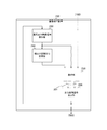
- FIG. 2 is a diagram illustrating a configuration example of the image processing device 200 according to the first embodiment of the present technology.
- the image processing apparatus 200 includes a selection unit 210, an output image signal generation unit 220, a previous output image signal holding unit 230, and an already output image signal holding unit 240.
- the selection unit 210 includes an input image signal from the imaging device 100, a previous output image signal held in the previous output image signal holding unit 230, and an existing output image signal held in the previous output image signal holding unit 240. Two image signals having a short distance in the color space are selected. Details of selection in the selection unit 210 will be described later.
- the output image signal generation unit 220 mixes two image signals 201 selected by the selection unit 210 and generates an output image signal. At this time, the output image signal generation unit 220 mixes them based on a predetermined mixing ratio. In the first embodiment of the present technology, this mixing is performed based on a one-to-one mixing ratio. Details of the mixing in the output image signal generation unit 220 will be described later.
- the immediately preceding output image signal holding unit 230 holds the output image signal generated by the output image signal generating unit 220 in the processing cycle immediately before the target processing cycle as the immediately preceding output image signal.
- the configuration of the immediately-preceding output image signal holding unit 230 will be described later.
- the already output image signal holding unit 240 holds an image signal based on the output image signal generated in the processing cycle two times before the target processing cycle as the already output image signal.
- the immediately-previous output image signal held in the immediately-previous output image signal holding unit 230 in the processing cycle immediately before the target cycle is the already-output image signal.
- the immediately preceding output image signal is an output image signal generated in the previous processing cycle, in the first embodiment of the present technology, it is generated in the processing cycle two times before the target processing cycle.
- the outputted output image signal is held as the already outputted image signal.
- the configuration of the already output image signal holding unit 240 will be described later.
- FIG. 3 is a diagram illustrating a configuration example of the immediately-preceding output image signal holding unit 230 and the already-output image signal holding unit 240 according to the first embodiment of the present technology.
- a represents the structure of the frame.
- a is a frame composed of 640 pixels ⁇ 480 lines.
- the imaging apparatus 100 outputs image signals to the image processing apparatus 200 in the order of the numbers given to a in FIG. For convenience, this number is treated as the address of the input image signal.
- the immediately-preceding output image signal holding unit 230 is configured by an image memory having the same number of storage areas as the number of image signals of one frame.
- the immediately preceding output image signal holding unit 230 holds the output image signal generated by the output image signal generating unit 220 as the immediately preceding output image signal. At this time, the output image signal is held in the storage area having the same address as the corresponding input image signal.
- the already-output image signal holding unit 240 is composed of an image memory having the same number of storage areas as the number of image signals in one frame.
- the previous output image signal holding unit 240 holds the previous output image signal held in the previous output image signal holding unit 230 as the previous output image signal.
- the original output image signal is held in the storage area having the same address as the corresponding input image signal.
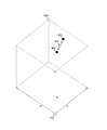
- FIG. 4 is a diagram illustrating a selection method according to the first embodiment of the present technology.
- the figure shows a selection method in the selection unit 210.
- the figure shows a color space in which R, G, and B signals constituting the image signal are associated with coordinates.
- a point 410 in the figure is a point where R, G, and B are all values “0”, and corresponds to an image signal corresponding to black.
- a point 420 is a point where all of R, G, and B have a maximum value, for example, a value “255” in 8-bit representation, and corresponds to an image signal corresponding to white.
- Points 401 to 403 are assumed to represent an input image signal, a previous output image signal, and an already output image signal, respectively.
- the selection unit 210 selects two images having a short distance in the color space from the three image signals of the input image signal, the previous output image signal, and the already output image signal. For this reason, the selection unit 210 calculates the distances in the color space of the three image signals.
- FIG. 5 is a diagram illustrating a configuration example of the selection unit 210 according to the first embodiment of the present technology.
- the selection unit 210 includes a color space distance calculation unit 211 and a short-distance image signal selection unit 212.
- the color space distance calculation unit 211 calculates the distances in the color space of the input image signal, the previous output image signal, and the already output image signal.
- the near-field image signal selection unit 212 selects two image signals at the shortest distance among the input image signal, the previous output image signal, and the already-output image signal based on the calculation result of the color space distance calculation unit 211, and outputs the selected image signal. To do. When these three image signals are equidistant, the previous output image signal and the previous output image signal are selected and output.
- FIG. 6 is a diagram illustrating a mixing method according to the first embodiment of the present technology. This figure shows a case where an image signal corresponding to points 402 and 403 described in FIG. 4 is mixed to generate an output image signal.
- mixing is performed based on a one-to-one mixing ratio. This mixing can be performed by calculating an average value for each coordinate of the two image signals. That is, it can be performed by calculating the image signal of the midpoint 404 in the color space for the two target image signals as shown in FIG. The calculation of the image signal of the midpoint 404 can be performed as follows.
- R ′, G ′, and B ′ are R, G, and B signals at the midpoint 404. Thereby, two image signals can be mixed based on a one-to-one ratio.
- FIG. 7 is a diagram illustrating a configuration example of the output image signal generation unit 220 according to the first embodiment of the present technology.
- the output image signal generation unit 220 includes a red image signal calculation unit 221, a green image signal calculation unit 222, and a blue image signal calculation unit 223.
- the red image signal calculation unit 221 calculates an average value (R ′) of image signals corresponding to red light among the two input image signals.
- the green image signal calculation unit 222 calculates an average value (G ′) of image signals corresponding to green light among the two input image signals.
- the blue image signal calculation unit 223 calculates an average value (B ′) of image signals corresponding to blue light among the two input image signals.
- the image signal composed of R ′, G ′, and B ′ calculated as described above is output from the output image signal generation unit 220 as an output image signal.
- FIG. 8 is a diagram for describing image processing according to the first embodiment of the present technology.
- “a” represents the relationship between the screen 430 and the pixels 431.
- #m represents the address of the image signal described above.
- B in the figure represents the processing in the image processing apparatus 200 when the image signal #m is the input image signal.
- the processing cycle #t of b in the figure corresponds to the attention processing cycle.
- the selection unit 210 selects two image signals having a short distance in the color space among the input image signal #m, the previous output image signal #m, and the already output image signal #m.
- the previous output image signal #m and the previous output image signal #m are the previous output image signal and the already output image signal corresponding to the pixel 431, respectively. These are held in the memory area of the address #m of the previous output image signal holding unit 230 and the already output image signal holding unit 240.
- the immediately preceding output image signal #m and the already output image signal #m are assumed as the selected image signals.
- the output image signal generation unit 220 mixes these two image signals to generate an output image signal.
- the output image signal is output from the image processing apparatus 200 and held in the memory area of the address #m of the immediately previous output image signal holding unit 230.
- the previous output image signal #m is held in the memory area at the address #m in the already output image signal holding unit 240. These are used as the immediately preceding output image signal #m and the already output image signal #m in the processing cycle subsequent to the attention processing cycle.
- the output image signal generated in the processing cycle immediately before the target processing cycle is the previous output image held in the previous output image signal holding unit 230 in the target processing cycle. Corresponds to the signal.
- the output image signal generated in the processing cycle two times before the target processing cycle is the output image already held in the output image signal holding unit 240 in the target processing cycle.
- processing cycle # (t-2) is the output image already held in the output image signal holding unit 240 in the target processing cycle.
- an output image signal generated in a certain processing cycle is used as a previous output image signal or the like in a subsequent processing cycle.
- a case where the input image signal #m and the already-output image signal #m are selected by the selection unit 210 can be assumed.
- an image signal obtained by capturing rain or the like is input, and the previous output image signal holding unit 230 and the previous output image signal holding unit 240 each hold an image signal before rain or the like is captured.
- the image processing will be described as an example.
- a water droplet such as rain is usually white, and the image signal #m corresponding thereto is close to the point 420 in the color space described with reference to FIG.
- the immediately-preceding output image signal #m and the already-output image signal #m are image signals before rain or the like is reflected, and thus are in positions away from the input image signal #m in the color space. Therefore, the selection unit 210 selects the previous output image signal #m and the already output image signal #m. Thereafter, these signals are mixed and output by the output image signal generation unit 220.
- the image signal in which rain or the like is reflected is removed by the image processing apparatus 200.
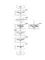
- FIG. 9 is a diagram illustrating an example of an image processing procedure according to the first embodiment of the present technology.
- the process shown in FIG. 6 is started when an image signal is input to the image processing apparatus 200.
- the distance in the color space among the input image signal, the previous output image signal, and the already output image signal is calculated by the selection unit 210 (step S901).
- step S902: Yes the selection unit 210 selects the previous output image signal and the already output image signal (step S904).
- the selection unit 210 selects the two image signals with the shortest distance (step S903).
- the output image signal generation unit 220 mixes the two selected image signals to generate an output image signal (step S905).
- the generated output image signal is newly held in the previous output image signal holding unit 230 as the previous output image signal (step S906).
- the previous output image signal held in the previous output image signal holding unit 230 is newly held in the already output image signal holding unit 240 as the already output image signal (step S907).
- the image processing apparatus 200 ends the process.
- FIG. 10 is a diagram illustrating the effect of the image processing according to the first embodiment of the present technology.
- the figure shows an example of a case where an image at the time of rain picked up by the image pickup apparatus 100 is processed by the image processing apparatus 200.
- the image processing apparatus 200 since the image signal in which raindrops are reflected is removed by the image processing apparatus 200, a background image from which rain has been removed can be obtained.
- the influence of rain or the like is removed by using the image memory for two frames of the previous output image signal holding unit and the already output image signal holding unit as the image memory.
- a background image can be generated.
- Second Embodiment> when image signals are mixed, mixing is performed based on a one-to-one mixing ratio. On the other hand, in the second embodiment of the present technology, the mixing is performed based on the mixing ratio corresponding to the saturation ratio of the image signal. Thereby, the ability to remove the influence of rain or the like can be improved.
- FIG. 11 is a diagram illustrating a mixing method according to the second embodiment of the present technology.
- This figure shows a case where mixing is performed based on a mixing ratio according to the saturation ratio of two image signals selected by the selection unit 210.
- this figure assumes that the points 402 and 403 are selected by the selection unit 210 as in the case described with reference to FIG.
- rain is achromatic such as white.
- other images such as buildings are often chromatic. Therefore, when mixing, mixing is performed at a mixing ratio according to the saturation of the image signal. Specifically, this is performed as follows. First, the saturation at points 402 and 403 is calculated.
- This saturation corresponds to the distance between the straight line passing through the points 410 and 420 and the points 402 and 403.
- This distance C can be calculated as follows. This is calculated for points 402 and 403, respectively. Let these calculation results be C1 and C2, respectively.
- the output image signal after mixing becomes an image signal having higher saturation than the output image signal in the first embodiment of the present technology.
- This output image signal is held in the immediately preceding output image signal holding unit 230 as the immediately preceding output image signal, and is selected by the selecting unit 210 in the next frame. Since the output image signal immediately before this has high saturation, the difference from the input image signal in which rain or the like close to an achromatic color is reflected becomes large. That is, the distance in the color space is increased. For this reason, the ability to remove the input image signal in which rain or the like is reflected can be improved.
- FIG. 12 is a diagram illustrating a configuration example of the output image signal generation unit 220 according to the second embodiment of the present technology.
- the output image signal generation unit 220 performs the above-described mixing on the two image signals selected by the selection unit 210 and generates an output image signal.
- the output image signal generation unit 220 includes a mixing ratio calculation unit 224, a red image signal calculation unit 225, a green image signal calculation unit 226, and a blue image signal calculation unit 227.
- the mixing ratio calculation unit 224 calculates a mixing ratio ( ⁇ described above) when the image signals selected by the selection unit 210 are mixed.
- the red image signal calculation unit 225 mixes the image signal corresponding to the red light out of the two input image signals based on the mixing ratio ( ⁇ ) calculated by the mixing ratio calculation unit 224 into a new red light.
- the corresponding image signal (R ′) is calculated.
- the green image signal calculation unit 226 calculates an image signal (G ′) corresponding to new green light by mixing image signals corresponding to green light out of the two input image signals based on ⁇ . is there.
- the blue image signal calculation unit 227 calculates an image signal (B ′) corresponding to new blue light by mixing image signals corresponding to blue light out of the two input image signals based on ⁇ . is there.
- the image signal composed of R ′, G ′, and B ′ calculated as described above is output from the output image signal generation unit 220 as an output image signal.
- the configuration of the image processing apparatus 200 is the same as that of the image processing apparatus 200 described with reference to FIG.
- an output image signal with higher saturation can be obtained, and the ability to remove the influence of rain and the like can be improved.
- the previous output image signal held in the previous output image signal holding unit 230 in the processing cycle immediately before the target cycle is used as the already output image signal.
- the previous output image signal is generated by mixing the previous output image signal and the output image signal. Thereby, the ability to remove the influence of rain and the like can be further improved.
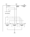
- FIG. 13 is a diagram illustrating a configuration example of the image processing device 200 according to the third embodiment of the present technology.
- the image processing apparatus 200 shown in the figure is different from the image processing apparatus 200 described with reference to FIG. 2 in that an output image signal generation unit 250 is further provided.
- the output image signal generator 250 generates an output image signal.
- the already output image signal generation unit 250 mixes the previous output image signal held in the previous output image signal holding unit 230 and the output image signal generated by the output image signal generation unit 220 based on a predetermined mixing ratio. Then, an already output image signal is generated. In the third embodiment of the present technology, this mixing is performed based on a one-to-one mixing ratio.
- the generated output image signal is held in the output image signal holding unit 240.
- the other configuration of the image processing apparatus 200 is the same as that of the image processing apparatus 200 described with reference to FIG.
- FIG. 14 is a diagram for describing image processing according to the third embodiment of the present technology.
- the output image signal #m and the previous output image signal #m in the attention processing cycle (processing cycle #t) are mixed to generate a new output image signal, and the memory at the address #m in the output image signal holding unit 240 Retained in the region.
- the mixing method described in FIG. 6 can be used.
- the distance in the color space between the output image signal and the immediately preceding output image signal becomes shorter. For this reason, in the next processing cycle, there is a higher probability that the output image signal and the previous output image signal are selected by the selection unit 210, and the ability to remove the input image signal in which rain or the like is reflected is improved.
- FIG. 15 is a diagram illustrating a configuration example of the already-output image signal generation unit 250 according to the third embodiment of the present technology.
- the output image signal generation unit 250 includes a red image signal calculation unit 251, a green image signal calculation unit 252, and a blue image signal calculation unit 253.
- the red image signal calculation unit 251, the green image signal calculation unit 252, and the blue image signal calculation unit 253 are the same as the red image signal calculation unit 221, the green image signal calculation unit 222, and the blue image signal calculation unit 223 described in FIG. Therefore, the description is omitted.
- the image signal calculated by these is output from the output image signal generation unit 250 as an output image signal.
- FIG. 16 is a diagram illustrating a configuration example of the already-output image signal generation unit 250 according to the fourth embodiment of the present technology.
- the output image signal generation unit 250 mixes the output image signal generated by the output image signal generation unit 220 and the output image signal generated by the output image signal generation unit 220 by mixing the output image signal generated by the output image signal generation unit 220. Is to be generated. At this time, the mixing is performed based on a mixing ratio corresponding to the saturation ratio of these two image signals.
- the output image signal generation unit 250 includes a mixing ratio calculation unit 254, a red image signal calculation unit 255, a green image signal calculation unit 256, and a blue image signal calculation unit 257.
- the mixing ratio calculation unit 254 calculates a mixing ratio when the output image signal and the previous output image signal are mixed.
- the configuration of the mixing ratio calculation unit 254 is the same as that of the mixing ratio calculation unit 224 described in FIG.
- the red image signal calculation unit 255, the green image signal calculation unit 256, and the blue image signal calculation unit 257 are the same as the red image signal calculation unit 225, the green image signal calculation unit 226, and the blue image signal calculation unit 227 described in FIG. Therefore, the description is omitted.
- the image signal calculated by these is output from the output image signal generation unit 250 as an output image signal.
- the configuration of the image processing apparatus 200 is the same as that of the image processing apparatus 200 described with reference to FIG.
- an output image signal with high saturation can be generated, and the ability to remove the influence of rain and the like can be further improved.
- the image memory required in the image processing apparatus that generates the background image from which the influence of rain or the like is removed is stored in the previous output image signal holding unit 230 and the previous output image signal holding.
- the image memory for two frames of the unit 240 can be used.
- the image memory can be reduced, and the image processing apparatus can be reduced in size and price.
- the processing procedure described in the above embodiment may be regarded as a method having a series of these procedures, and a program for causing a computer to execute these series of procedures or a recording medium storing the program. You may catch it.
- a recording medium for example, a CD (Compact Disc), an MD (MiniDisc), a DVD (Digital Versatile Disc), a memory card, a Blu-ray disc (Blu-ray (registered trademark) Disc), or the like can be used.
- this technique can also take the following structures.
- (1) The input image signal input in the attention processing cycle among the processing cycles executed for each of the time-series frames configured by the input image signal, and generated in the processing cycle immediately before the attention processing cycle. Two short distances in the color space from the previous output image signal which is the output image signal and the already output image signal which is the image signal based on the output image signal generated in the processing cycle two times before the target processing cycle.
- An image processing apparatus comprising: an output image signal generation unit configured to mix the selected two image signals based on a predetermined mixing ratio to generate the output image signal.
- (2) The image processing apparatus according to (1), wherein the output image signal generation unit performs the mixing based on the one-to-one mixing ratio.
- the image processing apparatus performs the mixing based on the mixing ratio according to a saturation ratio of the two image signals.
- An output image signal generation unit that generates the output image signal by mixing the output image signal generated in the attention processing cycle and the output image signal immediately before based on a predetermined second mixing ratio.
- the image processing apparatus according to any one of (1) to (3), further including: (5) The image processing apparatus according to (4), wherein the already-output image signal generation unit performs the mixing based on the second mixing ratio of 1: 1.
- the already-output image signal generation unit may perform the mixing based on the second mixing ratio according to a saturation ratio between the output image signal generated in the attention processing cycle and the immediately-preceding output image signal.
- the image processing apparatus according to (4), wherein: (7) a previous output image signal holding unit for holding the previous output image signal;
- the image processing apparatus according to any one of (1) to (6), further including an already output image signal holding unit that holds the already output image signal.
- an imaging device that supplies an image signal as an input image signal; In the processing cycle immediately before the target processing cycle and the input image signal input in the target processing cycle among the processing cycles executed for each time-series frame configured by the supplied input image signal The distance in the color space is short from the immediately-preceding output image signal that is the generated output image signal and the already-output image signal that is the image signal based on the output image signal generated in the processing cycle two steps before the target processing cycle.
- a selection unit for selecting two image signals An image processing system comprising: an output image signal generation unit configured to generate the output image signal by mixing the selected two image signals based on a predetermined mixing ratio. (9) The input image signal input in the attention processing cycle among the processing cycles executed for each of the time-series frames configured by the input image signal, and generated in the processing cycle immediately before the attention processing cycle. Two short distances in the color space from the previous output image signal which is the output image signal and the already output image signal which is the image signal based on the output image signal generated in the processing cycle two times before the target processing cycle.
- a selection procedure for selecting an image signal An image processing method comprising: an output image signal generation procedure for generating the output image signal by mixing the selected two image signals based on a predetermined mixing ratio.
- Imaging device 200 Image processing device 210 Selection part 211 Color space distance calculation part 212 Short-distance image signal selection part 220 Output image signal generation part 221, 225, 251, 255 Red image signal calculation part 222, 226, 252, 256 Green image Signal calculation unit 223, 227, 253, 257 Blue image signal calculation unit 224, 254 Mixing ratio calculation unit 230 Previous output image signal holding unit 240 Previous output image signal holding unit 250 Previous output image signal generation unit
Landscapes
- Engineering & Computer Science (AREA)
- Multimedia (AREA)
- Signal Processing (AREA)
- Physics & Mathematics (AREA)
- General Physics & Mathematics (AREA)
- Theoretical Computer Science (AREA)
- Computer Vision & Pattern Recognition (AREA)
- Image Processing (AREA)
- Color Television Image Signal Generators (AREA)
- Picture Signal Circuits (AREA)
Abstract
Description
1.第1の実施の形態(選択された画像信号の平均値を算出して出力画像信号を生成する場合の例)
2.第2の実施の形態(選択された画像信号の彩度に応じた混合比率に基づいて混合して出力画像信号を生成する場合の例)
3.第3の実施の形態(出力画像信号および直前画像信号から既出力画像信号を生成する場合の例)
4.第4の実施の形態(出力画像信号および直前画像信号の彩度に応じた混合比率に基づいて混合して既出力画像信号を生成する場合の例)
[システムの構成]
図1は、本技術の実施の形態におけるシステムの構成例を示す図である。同図の撮像装置100は、風景等を撮像して画像信号を出力する。この際、撮像装置100は、フレーム毎に画像信号を生成して順次出力する。このフレームは1画面分の画像信号であり、順次出力された時系列のフレームにより動画像が構成される。また、撮像装置100は、画像信号として赤色光に対応する画像信号(R)、緑色光に対応する画像信号(G)および青色光に対応する画像信号(B)からなる画像信号を出力することを想定する。
図2は、本技術の第1の実施の形態における画像処理装置200の構成例を示す図である。この画像処理装置200は、選択部210と、出力画像信号生成部220と、直前出力画像信号保持部230と、既出力画像信号保持部240とを備える。
図3は、本技術の第1の実施の形態における直前出力画像信号保持部230および既出力画像信号保持部240の構成例を示す図である。同図におけるaは、フレームの構成を表している。同図におけるaには、640画素×480ラインからなるフレームを例として挙げた。撮像装置100は、同図におけるaに付された番号の順に画像処理装置200に対して画像信号を出力する。便宜的にこの番号を入力画像信号のアドレスとして扱う。
図4は、本技術の第1の実施の形態における選択方法を示す図である。同図は、選択部210における選択方法を表している。また、同図は、画像信号を構成するR、GおよびBの各信号を座標に対応させた色空間を表している。同図の点410は、R、GおよびBが全て値「0」の点であり、黒に対応する画像信号に該当する。点420は、R、GおよびBの全てが最大値、例えば、8ビット表現で値「255」の点であり、白に対応する画像信号に該当する。また、点401乃至403は、それぞれ入力画像信号、直前出力画像信号および既出力画像信号を表すものと想定する。前述のように、選択部210は、入力画像信号、直前出力画像信号および既出力画像信号の3つ画像信号から色空間における距離が短い2つを選択する。このため、選択部210は、3つの画像信号の色空間における距離をそれぞれ算出する。

図5は、本技術の第1の実施の形態における選択部210の構成例を示す図である。この選択部210は、色空間距離算出部211と、近距離画像信号選択部212とを備える。
図6は、本技術の第1の実施の形態における混合方法を示す図である。同図は、図4において説明した点402および403に該当する画像信号に対して混合を行って、出力画像信号を生成する場合を表したものである。前述のように、本技術の第1の実施の形態では、1対1の混合比率に基づいて混合が行われる。この混合は、2つの画像信号の座標毎の平均値を算出することにより行うことができる。すなわち、同図に表したように対象となる2つの画像信号に対する色空間における中点404の画像信号を算出することにより行うことができる。中点404の画像信号の算出は、次式のように行うことができる。
R'=(R1+R2)/2
B'=(B1+B2)/2
G'=(G1+G2)/2
ただし、R'、G'およびB'は、中点404におけるR、GおよびBの各信号である。これにより、2つの画像信号を1対1の比率に基づいて混合することができる。
図7は、本技術の第1の実施の形態における出力画像信号生成部220の構成例を示す図である。この出力画像信号生成部220は、赤色画像信号算出部221と、緑色画像信号算出部222と、青色画像信号算出部223とを備える。
図8は、本技術の第1の実施の形態における画像処理を説明する図である。同図におけるaは、画面430と画素431との関係を表している。この画素431に対応する画像信号#mが画像処理装置200に入力された場合を想定する。ここで、#mは、前述した画像信号のアドレスを表している。同図におけるbは、画像信号#mを入力画像信号とした場合の画像処理装置200における処理を表している。なお、同図におけるbの処理サイクル#tは、注目処理サイクルに該当する。
図9は、本技術の第1の実施の形態における画像処理手順の一例を示す図である。同図の処理は、画像処理装置200に画像信号が入力されることにより開始される。まず、入力画像信号、直前出力画像信号および既出力画像信号の間の色空間における距離が選択部210により算出される(ステップS901)。次に、算出された3つの距離が等しいか否かが判断される(ステップS902)。3つの距離が等しい場合には(ステップS902:Yes)、選択部210は、直前出力画像信号および既出力画像信号を選択する(ステップS904)。一方、算出された3つの距離が等しくない場合には(ステップS902:No)、選択部210は、最も距離が短い2つの画像信号を選択する(ステップS903)。
図10は、本技術の第1の実施の形態における画像処理の効果を示す図である。同図は、撮像装置100により撮像された降雨時の画像を画像処理装置200により処理した場合の例を表している。図8において説明したように、雨滴が写り込んだ画像信号は、画像処理装置200により除去されるため、雨が除去された背景画像を得ることができる。
上述の実施の形態では、画像信号を混合する際、1対1の混合比率に基づいて混合を行っていた。これに対し、本技術の第2の実施の形態では、画像信号の彩度の比率に応じた混合比率に基づいて混合を行う。これにより、雨等の影響を除去する能力を向上させることができる。
図11は、本技術の第2の実施の形態における混合方法を示す図である。同図は、選択部210により選択された2つの画像信号の彩度の比率に応じた混合比率に基づいて混合を行う場合を表したものである。また、同図は、図6において説明した場合と同様に点402および403が選択部210により選択された場合を想定したものである。通常、雨等は白色等の無彩色である。一方、他の画像、例えば建物等は有彩色であることが多い。そこで、混合する際、画像信号の彩度に応じた混合比率により混合を行う。具体的には、次のように行う。まず、点402および403における彩度を算出する。この彩度は、点410および420を通る直線と点402および403との間の距離に相当する。この距離Cは、次式のように算出することができる。

α=C1/(C1+C2) (ただし、C1>C2の場合)
α=C2/(C1+C2) (ただし、C1<C2の場合)
α=0.5 (ただし、C1=C2の場合)
(a)C1>C2の場合
R'=α×R1+(1-α)×R2
B'=α×B1+(1-α)×B2
G'=α×G1+(1-α)×G2
(b)C1<C2の場合
R'=(1-α)×R1+α×R2
B'=(1-α)×B1+α×B2
G'=(1-α)×G1+α×G2
(c)C1=C2の場合
図6において説明した平均値の算出と同様に行うことができる。
図12は、本技術の第2の実施の形態における出力画像信号生成部220の構成例を示す図である。この出力画像信号生成部220は、選択部210により選択された2つの画像信号に対して、上述した混合を行って出力画像信号を生成するものである。またこの出力画像信号生成部220は、混合比率算出部224と、赤色画像信号算出部225と、緑色画像信号算出部226と、青色画像信号算出部227とを備える。
上述の実施の形態では、既出力画像信号として、注目サイクルの1つ前の処理サイクルにおいて直前出力画像信号保持部230に保持されていた直前出力画像信号を用いていた。これに対し、本技術の第3の実施の形態では、この直前出力画像信号と出力画像信号とを混合して既出力画像信号を生成する。これにより、雨等の影響を除去する能力をさらに向上させることができる。
図13は、本技術の第3の実施の形態における画像処理装置200の構成例を示す図である。同図の画像処理装置200は、既出力画像信号生成部250をさらに備える点で、図2において説明した画像処理装置200と異なる。
図14は、本技術の第3の実施の形態における画像処理を説明する図である。注目処理サイクル(処理サイクル#t)における出力画像信号#mおよび直前出力画像信号#mが混合されて、新たな既出力画像信号が生成され、既出力画像信号保持部240のアドレス#mのメモリ領域に保持される。この混合方法として、図6において説明した混合方法を使用することができる。すなわち、出力画像信号および直前出力画像信号の平均値を算出して新たな既出力画像信号を生成する方法を使用することができる。これにより、図8において説明した画像処理方法と比べて、既出力画像信号および直前出力画像信号の色空間における距離は、より短くなる。このため、次の処理サイクルにおいて選択部210により既出力画像信号および直前出力画像信号が選択される確率が高くなり、雨等が写り込んだ入力画像信号の除去能力が向上する。
図15は、本技術の第3の実施の形態における既出力画像信号生成部250の構成例を示す図である。この既出力画像信号生成部250は、赤色画像信号算出部251と、緑色画像信号算出部252と、青色画像信号算出部253とを備える。
上述の第3の実施の形態では、既出力画像信号を生成する際、1対1の混合比率に基づいて混合を行っていた。これに対し、本技術の第4の実施の形態では、画像信号の彩度の比率に応じた混合比率に基づいて混合を行う。これにより、雨等の影響を除去する能力をさらに向上させることができる。
図16は、本技術の第4の実施の形態における既出力画像信号生成部250の構成例を示す図である。この既出力画像信号生成部250は、直前出力画像信号保持部230に保持されていた直前出力画像信号と出力画像信号生成部220により生成された出力画像信号とを混合し、既出力画像信号を生成するものである。この際、これら2つの画像信号の彩度の比率に応じた混合比率に基づいて混合を行う。また、この既出力画像信号生成部250は、混合比率算出部254と、赤色画像信号算出部255と、緑色画像信号算出部256と、青色画像信号算出部257とを備える。
(1)入力画像信号により構成される時系列のフレーム毎に実行される処理サイクルのうちの注目処理サイクルにおいて入力される前記入力画像信号と前記注目処理サイクルの1つ前の処理サイクルにおいて生成された出力画像信号である直前出力画像信号と前記注目処理サイクルの2つ前の処理サイクルにおいて生成された前記出力画像信号に基づく画像信号である既出力画像信号とから色空間における距離が短い2つの画像信号を選択する選択部と、
前記選択された前記2つの画像信号を所定の混合比率に基づいて混合して前記出力画像信号を生成する出力画像信号生成部と
を具備する画像処理装置。
(2)前記出力画像信号生成部は、1対1の前記混合比率に基づいて前記混合を行う前記(1)に記載の画像処理装置。
(3)前記出力画像信号生成部は、前記2つの画像信号の彩度の比率に応じた前記混合比率に基づいて前記混合を行う前記(1)に記載の画像処理装置。
(4)前記注目処理サイクルにおいて生成された前記出力画像信号と前記直前出力画像信号とを所定の第2の混合比率に基づいて混合して前記既出力画像信号を生成する既出力画像信号生成部をさらに具備する前記(1)から(3)のいずれかに記載の画像処理装置。
(5)前記既出力画像信号生成部は、1対1の前記第2の混合比率に基づいて前記混合を行う前記(4)に記載の画像処理装置。
(6)前記既出力画像信号生成部は、前記注目処理サイクルにおいて生成された前記出力画像信号と前記直前出力画像信号との彩度の比率に応じた前記第2の混合比率に基づいて前記混合を行う前記(4)に記載の画像処理装置。
(7)前記直前出力画像信号を保持する直前出力画像信号保持部と、
前記既出力画像信号を保持する既出力画像信号保持部と
をさらに具備する前記(1)から(6)のいずれかに記載の画像処理装置。
(8)画像信号を入力画像信号として供給する撮像装置と、
前記供給された前記入力画像信号により構成される時系列のフレーム毎に実行される処理サイクルのうちの注目処理サイクルにおいて入力される前記入力画像信号と前記注目処理サイクルの1つ前の処理サイクルにおいて生成された出力画像信号である直前出力画像信号と前記注目処理サイクルの2つ前の処理サイクルにおいて生成された前記出力画像信号に基づく画像信号である既出力画像信号とから色空間における距離が短い2つの画像信号を選択する選択部と、
前記選択された前記2つの画像信号を所定の混合比率に基づいて混合して前記出力画像信号を生成する出力画像信号生成部と
を具備する画像処理システム。
(9)入力画像信号により構成される時系列のフレーム毎に実行される処理サイクルのうちの注目処理サイクルにおいて入力される前記入力画像信号と前記注目処理サイクルの1つ前の処理サイクルにおいて生成された出力画像信号である直前出力画像信号と前記注目処理サイクルの2つ前の処理サイクルにおいて生成された前記出力画像信号に基づく画像信号である既出力画像信号とから色空間における距離が短い2つの画像信号を選択する選択手順と、
前記選択された前記2つの画像信号を所定の混合比率に基づいて混合して前記出力画像信号を生成する出力画像信号生成手順と
を具備する画像処理方法。
200 画像処理装置
210 選択部
211 色空間距離算出部
212 近距離画像信号選択部
220 出力画像信号生成部
221、225、251、255 赤色画像信号算出部
222、226、252、256 緑色画像信号算出部
223、227、253、257 青色画像信号算出部
224、254 混合比率算出部
230 直前出力画像信号保持部
240 既出力画像信号保持部
250 既出力画像信号生成部
Claims (9)
- 入力画像信号により構成される時系列のフレーム毎に実行される処理サイクルのうちの注目処理サイクルにおいて入力される前記入力画像信号と前記注目処理サイクルの1つ前の処理サイクルにおいて生成された出力画像信号である直前出力画像信号と前記注目処理サイクルの2つ前の処理サイクルにおいて生成された前記出力画像信号に基づく画像信号である既出力画像信号とから色空間における距離が短い2つの画像信号を選択する選択部と、
前記選択された前記2つの画像信号を所定の混合比率に基づいて混合して前記出力画像信号を生成する出力画像信号生成部と
を具備する画像処理装置。 - 前記出力画像信号生成部は、1対1の前記混合比率に基づいて前記混合を行う請求項1記載の画像処理装置。
- 前記出力画像信号生成部は、前記2つの画像信号の彩度の比率に応じた前記混合比率に基づいて前記混合を行う請求項1記載の画像処理装置。
- 前記注目処理サイクルにおいて生成された前記出力画像信号と前記直前出力画像信号とを所定の第2の混合比率に基づいて混合して前記既出力画像信号を生成する既出力画像信号生成部をさらに具備する請求項1記載の画像処理装置。
- 前記既出力画像信号生成部は、1対1の前記第2の混合比率に基づいて前記混合を行う請求項4記載の画像処理装置。
- 前記既出力画像信号生成部は、前記注目処理サイクルにおいて生成された前記出力画像信号と前記直前出力画像信号との彩度の比率に応じた前記第2の混合比率に基づいて前記混合を行う請求項4記載の画像処理装置。
- 前記直前出力画像信号を保持する直前出力画像信号保持部と、
前記既出力画像信号を保持する既出力画像信号保持部と
をさらに具備する請求項1記載の画像処理装置。 - 画像信号を入力画像信号として供給する撮像装置と、
前記供給された前記入力画像信号により構成される時系列のフレーム毎に実行される処理サイクルのうちの注目処理サイクルにおいて入力される前記入力画像信号と前記注目処理サイクルの1つ前の処理サイクルにおいて生成された出力画像信号である直前出力画像信号と前記注目処理サイクルの2つ前の処理サイクルにおいて生成された前記出力画像信号に基づく画像信号である既出力画像信号とから色空間における距離が短い2つの画像信号を選択する選択部と、
前記選択された前記2つの画像信号を所定の混合比率に基づいて混合して前記出力画像信号を生成する出力画像信号生成部と
を具備する画像処理システム。 - 入力画像信号により構成される時系列のフレーム毎に実行される処理サイクルのうちの注目処理サイクルにおいて入力される前記入力画像信号と前記注目処理サイクルの1つ前の処理サイクルにおいて生成された出力画像信号である直前出力画像信号と前記注目処理サイクルの2つ前の処理サイクルにおいて生成された前記出力画像信号に基づく画像信号である既出力画像信号とから色空間における距離が短い2つの画像信号を選択する選択手順と、
前記選択された前記2つの画像信号を所定の混合比率に基づいて混合して前記出力画像信号を生成する出力画像信号生成手順と
を具備する画像処理方法。
Priority Applications (3)
| Application Number | Priority Date | Filing Date | Title |
|---|---|---|---|
| JP2017507523A JPWO2016152190A1 (ja) | 2015-03-20 | 2016-01-12 | 画像処理装置、画像処理システムおよび画像処理方法 |
| CN201680015609.3A CN107431742B (zh) | 2015-03-20 | 2016-01-12 | 图像处理装置、图像处理系统和图像处理方法 |
| US15/554,926 US10158790B2 (en) | 2015-03-20 | 2016-01-12 | Image processing apparatus, image processing system, and image processing method |
Applications Claiming Priority (2)
| Application Number | Priority Date | Filing Date | Title |
|---|---|---|---|
| JP2015057773 | 2015-03-20 | ||
| JP2015-057773 | 2015-03-20 |
Publications (1)
| Publication Number | Publication Date |
|---|---|
| WO2016152190A1 true WO2016152190A1 (ja) | 2016-09-29 |
Family
ID=56977188
Family Applications (1)
| Application Number | Title | Priority Date | Filing Date |
|---|---|---|---|
| PCT/JP2016/050641 Ceased WO2016152190A1 (ja) | 2015-03-20 | 2016-01-12 | 画像処理装置、画像処理システムおよび画像処理方法 |
Country Status (4)
| Country | Link |
|---|---|
| US (1) | US10158790B2 (ja) |
| JP (1) | JPWO2016152190A1 (ja) |
| CN (1) | CN107431742B (ja) |
| WO (1) | WO2016152190A1 (ja) |
Families Citing this family (4)
| Publication number | Priority date | Publication date | Assignee | Title |
|---|---|---|---|---|
| JP5915960B1 (ja) | 2015-04-17 | 2016-05-11 | パナソニックIpマネジメント株式会社 | 動線分析システム及び動線分析方法 |
| JP5909711B1 (ja) * | 2015-06-15 | 2016-04-27 | パナソニックIpマネジメント株式会社 | 動線分析システム及び動線表示方法 |
| JP6558579B2 (ja) * | 2015-12-24 | 2019-08-14 | パナソニックIpマネジメント株式会社 | 動線分析システム及び動線分析方法 |
| US10497130B2 (en) | 2016-05-10 | 2019-12-03 | Panasonic Intellectual Property Management Co., Ltd. | Moving information analyzing system and moving information analyzing method |
Citations (4)
| Publication number | Priority date | Publication date | Assignee | Title |
|---|---|---|---|---|
| JPH07143448A (ja) * | 1993-11-19 | 1995-06-02 | Fujitsu General Ltd | 静止画表示装置 |
| JP2005236472A (ja) * | 2004-02-18 | 2005-09-02 | Seiko Epson Corp | 動画編集装置 |
| WO2008111549A1 (ja) * | 2007-03-15 | 2008-09-18 | Kansai University | 移動物体ノイズ除去処理装置及び移動物体ノイズ除去処理プログラム |
| JP2010141663A (ja) * | 2008-12-12 | 2010-06-24 | Victor Co Of Japan Ltd | 撮像装置 |
Family Cites Families (9)
| Publication number | Priority date | Publication date | Assignee | Title |
|---|---|---|---|---|
| JPS592227B2 (ja) * | 1978-08-21 | 1984-01-17 | 株式会社日立製作所 | 雑音除去方式 |
| CA2646791C (en) * | 1999-12-28 | 2012-02-28 | Sony Corporation | Signal processing device and method, and recording medium |
| JP4280614B2 (ja) * | 2003-12-09 | 2009-06-17 | Okiセミコンダクタ株式会社 | ノイズ低減回路及び方法 |
| JP4506308B2 (ja) | 2004-07-02 | 2010-07-21 | 三菱電機株式会社 | 画像処理装置及び該画像処理装置を用いた画像監視システム |
| US20060170769A1 (en) * | 2005-01-31 | 2006-08-03 | Jianpeng Zhou | Human and object recognition in digital video |
| US20080158428A1 (en) * | 2007-01-03 | 2008-07-03 | Tvia, Inc. | Dynamic Cross Color Elimination |
| JP2009027604A (ja) * | 2007-07-23 | 2009-02-05 | Elmo Co Ltd | ノイズ低減装置およびノイズ低減方法 |
| US20100238354A1 (en) * | 2009-03-18 | 2010-09-23 | Shmueli Yaron | Method and system for adaptive noise reduction filtering |
| WO2016067529A1 (ja) * | 2014-10-30 | 2016-05-06 | パナソニックIpマネジメント株式会社 | 画像処理装置、画像表示システム及びそれを備える車両並びに画像処理方法及びそれを実行させるプログラム |
-
2016
- 2016-01-12 JP JP2017507523A patent/JPWO2016152190A1/ja active Pending
- 2016-01-12 CN CN201680015609.3A patent/CN107431742B/zh not_active Expired - Fee Related
- 2016-01-12 WO PCT/JP2016/050641 patent/WO2016152190A1/ja not_active Ceased
- 2016-01-12 US US15/554,926 patent/US10158790B2/en active Active
Patent Citations (4)
| Publication number | Priority date | Publication date | Assignee | Title |
|---|---|---|---|---|
| JPH07143448A (ja) * | 1993-11-19 | 1995-06-02 | Fujitsu General Ltd | 静止画表示装置 |
| JP2005236472A (ja) * | 2004-02-18 | 2005-09-02 | Seiko Epson Corp | 動画編集装置 |
| WO2008111549A1 (ja) * | 2007-03-15 | 2008-09-18 | Kansai University | 移動物体ノイズ除去処理装置及び移動物体ノイズ除去処理プログラム |
| JP2010141663A (ja) * | 2008-12-12 | 2010-06-24 | Victor Co Of Japan Ltd | 撮像装置 |
Also Published As
| Publication number | Publication date |
|---|---|
| CN107431742A (zh) | 2017-12-01 |
| CN107431742B (zh) | 2020-06-16 |
| US20180048789A1 (en) | 2018-02-15 |
| JPWO2016152190A1 (ja) | 2018-01-11 |
| US10158790B2 (en) | 2018-12-18 |
Similar Documents
| Publication | Publication Date | Title |
|---|---|---|
| JP5295431B2 (ja) | 画像処理装置 | |
| US10096077B2 (en) | Information embedding device, information embedding method, and recording medium storing program | |
| JP6056511B2 (ja) | 画像処理装置、方法、及びプログラム、並びに撮像装置 | |
| JPWO2016152190A1 (ja) | 画像処理装置、画像処理システムおよび画像処理方法 | |
| CN107590791A (zh) | 图像增强方法以及图像处理装置 | |
| CN109801279A (zh) | 图像中的目标检测方法及装置、电子设备、存储介质 | |
| JP2017157902A (ja) | 信号処理装置、撮像装置および信号処理方法 | |
| KR101733309B1 (ko) | 4 칼라 이미지 센서를 위해 듀얼 isp를 갖는 카메라 시스템 | |
| DE602007012585D1 (de) | Verfahren zum detektieren eines beweglichen objekts in einer sequenz von durch eine bewegliche kamera erfassten bildern, computersystem und computerprogrammprodukt | |
| JP5818050B1 (ja) | ステータス判定システム | |
| US9240065B2 (en) | Image processing apparatus and image processing method | |
| KR101819984B1 (ko) | 실시간 영상 합성 방법 | |
| JP6305194B2 (ja) | 画像処理装置、撮像装置および画像処理方法 | |
| JP2004201283A5 (ja) | ||
| JP2009237650A (ja) | 画像処理装置及び撮像装置 | |
| US20150262339A1 (en) | Image processing apparatus, image processing system, and image processing method | |
| CN104851114A (zh) | 一种实现图像局部变色的方法及终端 | |
| JP2017045273A (ja) | 画像処理装置、画像処理方法、及びプログラム | |
| JP2002152762A (ja) | 画像処理装置および画像処理プログラムを記録した記録媒体 | |
| JP2016082390A (ja) | 信号処理装置 | |
| JP5103436B2 (ja) | 画像処理装置、画像処理方法及び画像処理プログラム | |
| JP2007221367A (ja) | 画像伝送装置および画像伝送システム | |
| KR100776385B1 (ko) | 에지 향상과 노이즈 제거를 위한 컬러 보간 장치 | |
| WO2016009729A1 (ja) | 撮像制御装置、撮像装置および撮像制御方法 | |
| JP2008186124A (ja) | 画像データ処理方法、画像データ処理プログラム及び画像データ処理装置 |
Legal Events
| Date | Code | Title | Description |
|---|---|---|---|
| 121 | Ep: the epo has been informed by wipo that ep was designated in this application |
Ref document number: 16768093 Country of ref document: EP Kind code of ref document: A1 |
|
| ENP | Entry into the national phase |
Ref document number: 2017507523 Country of ref document: JP Kind code of ref document: A |
|
| WWE | Wipo information: entry into national phase |
Ref document number: 15554926 Country of ref document: US |
|
| NENP | Non-entry into the national phase |
Ref country code: DE |
|
| 122 | Ep: pct application non-entry in european phase |
Ref document number: 16768093 Country of ref document: EP Kind code of ref document: A1 |