WO2016151938A1 - レーザレーダ装置及び走行体 - Google Patents
レーザレーダ装置及び走行体 Download PDFInfo
- Publication number
- WO2016151938A1 WO2016151938A1 PCT/JP2015/082562 JP2015082562W WO2016151938A1 WO 2016151938 A1 WO2016151938 A1 WO 2016151938A1 JP 2015082562 W JP2015082562 W JP 2015082562W WO 2016151938 A1 WO2016151938 A1 WO 2016151938A1
- Authority
- WO
- WIPO (PCT)
- Prior art keywords
- light
- light receiving
- laser
- target area
- radar device
- Prior art date
Links
- 230000003287 optical effect Effects 0.000 claims abstract description 25
- 238000005259 measurement Methods 0.000 claims description 93
- 230000005540 biological transmission Effects 0.000 claims description 9
- 230000004907 flux Effects 0.000 claims description 4
- 238000003384 imaging method Methods 0.000 description 7
- 238000010586 diagram Methods 0.000 description 2
- 230000001678 irradiating effect Effects 0.000 description 2
- 230000004048 modification Effects 0.000 description 2
- 238000012986 modification Methods 0.000 description 2
- 230000002093 peripheral effect Effects 0.000 description 2
- 238000012876 topography Methods 0.000 description 2
- 238000006243 chemical reaction Methods 0.000 description 1
- 239000000470 constituent Substances 0.000 description 1
- 230000006866 deterioration Effects 0.000 description 1
- 230000007613 environmental effect Effects 0.000 description 1
- 230000010365 information processing Effects 0.000 description 1
- 230000004043 responsiveness Effects 0.000 description 1
- 238000002834 transmittance Methods 0.000 description 1
- 230000000007 visual effect Effects 0.000 description 1
Images


Classifications
-
- G—PHYSICS
- G01—MEASURING; TESTING
- G01S—RADIO DIRECTION-FINDING; RADIO NAVIGATION; DETERMINING DISTANCE OR VELOCITY BY USE OF RADIO WAVES; LOCATING OR PRESENCE-DETECTING BY USE OF THE REFLECTION OR RERADIATION OF RADIO WAVES; ANALOGOUS ARRANGEMENTS USING OTHER WAVES
- G01S17/00—Systems using the reflection or reradiation of electromagnetic waves other than radio waves, e.g. lidar systems
- G01S17/02—Systems using the reflection of electromagnetic waves other than radio waves
- G01S17/06—Systems determining position data of a target
- G01S17/42—Simultaneous measurement of distance and other co-ordinates
-
- B—PERFORMING OPERATIONS; TRANSPORTING
- B61—RAILWAYS
- B61L—GUIDING RAILWAY TRAFFIC; ENSURING THE SAFETY OF RAILWAY TRAFFIC
- B61L15/00—Indicators provided on the vehicle or train for signalling purposes
- B61L15/0081—On-board diagnosis or maintenance
-
- B—PERFORMING OPERATIONS; TRANSPORTING
- B61—RAILWAYS
- B61L—GUIDING RAILWAY TRAFFIC; ENSURING THE SAFETY OF RAILWAY TRAFFIC
- B61L23/00—Control, warning or like safety means along the route or between vehicles or trains
-
- G—PHYSICS
- G01—MEASURING; TESTING
- G01B—MEASURING LENGTH, THICKNESS OR SIMILAR LINEAR DIMENSIONS; MEASURING ANGLES; MEASURING AREAS; MEASURING IRREGULARITIES OF SURFACES OR CONTOURS
- G01B11/00—Measuring arrangements characterised by the use of optical techniques
- G01B11/24—Measuring arrangements characterised by the use of optical techniques for measuring contours or curvatures
-
- G—PHYSICS
- G01—MEASURING; TESTING
- G01C—MEASURING DISTANCES, LEVELS OR BEARINGS; SURVEYING; NAVIGATION; GYROSCOPIC INSTRUMENTS; PHOTOGRAMMETRY OR VIDEOGRAMMETRY
- G01C3/00—Measuring distances in line of sight; Optical rangefinders
- G01C3/02—Details
- G01C3/06—Use of electric means to obtain final indication
-
- G—PHYSICS
- G01—MEASURING; TESTING
- G01S—RADIO DIRECTION-FINDING; RADIO NAVIGATION; DETERMINING DISTANCE OR VELOCITY BY USE OF RADIO WAVES; LOCATING OR PRESENCE-DETECTING BY USE OF THE REFLECTION OR RERADIATION OF RADIO WAVES; ANALOGOUS ARRANGEMENTS USING OTHER WAVES
- G01S17/00—Systems using the reflection or reradiation of electromagnetic waves other than radio waves, e.g. lidar systems
- G01S17/88—Lidar systems specially adapted for specific applications
- G01S17/93—Lidar systems specially adapted for specific applications for anti-collision purposes
- G01S17/931—Lidar systems specially adapted for specific applications for anti-collision purposes of land vehicles
-
- G—PHYSICS
- G01—MEASURING; TESTING
- G01S—RADIO DIRECTION-FINDING; RADIO NAVIGATION; DETERMINING DISTANCE OR VELOCITY BY USE OF RADIO WAVES; LOCATING OR PRESENCE-DETECTING BY USE OF THE REFLECTION OR RERADIATION OF RADIO WAVES; ANALOGOUS ARRANGEMENTS USING OTHER WAVES
- G01S7/00—Details of systems according to groups G01S13/00, G01S15/00, G01S17/00
- G01S7/48—Details of systems according to groups G01S13/00, G01S15/00, G01S17/00 of systems according to group G01S17/00
- G01S7/481—Constructional features, e.g. arrangements of optical elements
- G01S7/4816—Constructional features, e.g. arrangements of optical elements of receivers alone
-
- G—PHYSICS
- G01—MEASURING; TESTING
- G01S—RADIO DIRECTION-FINDING; RADIO NAVIGATION; DETERMINING DISTANCE OR VELOCITY BY USE OF RADIO WAVES; LOCATING OR PRESENCE-DETECTING BY USE OF THE REFLECTION OR RERADIATION OF RADIO WAVES; ANALOGOUS ARRANGEMENTS USING OTHER WAVES
- G01S7/00—Details of systems according to groups G01S13/00, G01S15/00, G01S17/00
- G01S7/48—Details of systems according to groups G01S13/00, G01S15/00, G01S17/00 of systems according to group G01S17/00
- G01S7/481—Constructional features, e.g. arrangements of optical elements
- G01S7/4817—Constructional features, e.g. arrangements of optical elements relating to scanning
-
- G—PHYSICS
- G01—MEASURING; TESTING
- G01S—RADIO DIRECTION-FINDING; RADIO NAVIGATION; DETERMINING DISTANCE OR VELOCITY BY USE OF RADIO WAVES; LOCATING OR PRESENCE-DETECTING BY USE OF THE REFLECTION OR RERADIATION OF RADIO WAVES; ANALOGOUS ARRANGEMENTS USING OTHER WAVES
- G01S7/00—Details of systems according to groups G01S13/00, G01S15/00, G01S17/00
- G01S7/48—Details of systems according to groups G01S13/00, G01S15/00, G01S17/00 of systems according to group G01S17/00
- G01S7/483—Details of pulse systems
- G01S7/486—Receivers
- G01S7/4865—Time delay measurement, e.g. time-of-flight measurement, time of arrival measurement or determining the exact position of a peak
-
- G—PHYSICS
- G02—OPTICS
- G02B—OPTICAL ELEMENTS, SYSTEMS OR APPARATUS
- G02B19/00—Condensers, e.g. light collectors or similar non-imaging optics
- G02B19/0004—Condensers, e.g. light collectors or similar non-imaging optics characterised by the optical means employed
- G02B19/0009—Condensers, e.g. light collectors or similar non-imaging optics characterised by the optical means employed having refractive surfaces only
- G02B19/0014—Condensers, e.g. light collectors or similar non-imaging optics characterised by the optical means employed having refractive surfaces only at least one surface having optical power
-
- G—PHYSICS
- G02—OPTICS
- G02B—OPTICAL ELEMENTS, SYSTEMS OR APPARATUS
- G02B26/00—Optical devices or arrangements for the control of light using movable or deformable optical elements
- G02B26/08—Optical devices or arrangements for the control of light using movable or deformable optical elements for controlling the direction of light
- G02B26/10—Scanning systems
- G02B26/101—Scanning systems with both horizontal and vertical deflecting means, e.g. raster or XY scanners
-
- G—PHYSICS
- G08—SIGNALLING
- G08G—TRAFFIC CONTROL SYSTEMS
- G08G1/00—Traffic control systems for road vehicles
- G08G1/16—Anti-collision systems
-
- G—PHYSICS
- G02—OPTICS
- G02B—OPTICAL ELEMENTS, SYSTEMS OR APPARATUS
- G02B27/00—Optical systems or apparatus not provided for by any of the groups G02B1/00 - G02B26/00, G02B30/00
- G02B27/09—Beam shaping, e.g. changing the cross-sectional area, not otherwise provided for
- G02B27/0938—Using specific optical elements
- G02B27/095—Refractive optical elements
- G02B27/0955—Lenses
Definitions
- the present invention relates to a laser radar device that generates three-dimensional information of a measurement target area by scanning a laser beam, and a traveling body.
- three-dimensional information of the measurement target area is obtained from the distribution of light reception signals obtained by irradiating laser light while scanning the measurement target area and receiving reflected light from an object or the like present in the measurement target area by the light receiving element.
- Laser radar devices are known to generate.
- a scanner is provided on each of the transmitting side of the laser beam and the receiving side of the reflected light, and is adjusted to the mirror angle (transmission angle of the laser beam) of the scanner on the transmitting side during scanning. Reflected light is made to enter the light receiving element by adjusting the mirror angle (light receiving angle of the reflected light) of the scanner on the light receiving side as needed.
- the scanners are provided on both the light transmission side and the light reception side, there is a problem that the size of the entire laser radar apparatus is increased.
- the laser radar device includes a long light receiving element array in which long light receiving elements are arranged in an array in a direction orthogonal to the long direction of the light receiving element, a transimpedance amplifier array for amplifying a received signal, and a transimpedance amplifier array.
- Patent No. 5602225 gazette
- the entire long light receiving element array becomes large. there were.
- an addition circuit for adding the reception signals received by the respective long light receiving elements arranged in an array is required, and there is a problem that the device configuration and the signal processing become complicated.
- the present invention has been made in view of the above, and it is an object of the present invention to provide a laser radar device capable of realizing scanless on the light receiving side with a simple configuration while achieving downsizing of the light receiving element, and a running body. I assume.
- the present invention provides a laser light source, a light transmitting side lens for forming laser light emitted from the laser light source into a point shape, and a laser light formed into a point shape
- a scanner that irradiates while scanning in a first direction of a measurement target area and a second direction orthogonal to the first direction, a light receiving side lens that receives reflected light reflected from the measurement target area, and a light receiving side lens
- a light receiving side optical system for collecting the reflected light received in the first direction and the second direction, and a reflected light collected by the light receiving side optical system are received, and laser light included in the received reflected light
- a light receiving unit that outputs a received signal based on the information processing unit is provided, and an information generating unit that generates three-dimensional information of a measurement target area based on the received signal output from the light receiving unit.
- the light receiving side optical system condenses the reflected light received by the light receiving side lens in the first direction and the second direction, and the reflected light collected by the light receiving side optical system, Since the light receiving portion for outputting a reception signal based on the laser light contained in the received reflected light is provided, the light receiving element of the light receiving portion can be miniaturized, and the entire measurement target area can be used as a sensor field of view of the light receiving element. It can be accommodated and scanless on the light receiving side can be realized with a simple configuration.
- a single light receiving element may be provided. According to this configuration, since the entire area to be measured can be contained in the sensor field of view of a single light receiving element, an addition circuit for adding received signals of the light receiving element is not necessary, and simplification of the circuit configuration can be realized.
- the light receiving side optical system includes a relay lens disposed near or at the back of the image forming position of the light receiving side lens, and a focusing lens for focusing the substantially parallel light flux transmitted from the relay lens toward the light receiving portion. You may have. According to this configuration, the imaging information of the light receiving side lens can be focused on the light receiving section with a simple configuration in which two types of lenses are combined.
- the information generation unit controls the light transmission of the scanner when the laser light is irradiated and the distance information to the measurement target area acquired from the light round trip time from the irradiation of the laser light to the reception by the light reception unit.
- Three-dimensional information of the area to be measured may be generated from each position information of the first direction and the second direction acquired based on the angle. According to this configuration, it is not necessary to acquire spatial position coordinates of the received signal due to the field-of-view scan on the light receiving side, so the load of signal processing for generating three-dimensional information can be reduced.
- the above-described laser radar device may be mounted on a traveling body. According to this configuration, three-dimensional information of the traveling route of the traveling body can be constantly acquired, and driving support of the traveling body can be performed.
- the light receiving side optical system for collecting the reflected light received by the light receiving side lens in the first direction and the second direction and the reflected light collected by the light receiving side optical system are received. Since the light receiving portion for outputting a reception signal based on the laser light contained in the received reflected light is provided, the light receiving element of the light receiving portion can be miniaturized, and the entire measurement target area can be used as a sensor field of view of the light receiving element. It can be accommodated and scanless on the light receiving side can be realized with a simple configuration.
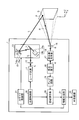
- FIG. 1 is a schematic configuration diagram of a laser radar device according to the present embodiment.
- FIG. 2 is a schematic view showing a peripheral configuration including the light receiving side optical system.
- FIG. 3A is a view showing a modified example of the light receiving element.
- FIG. 3B is a view showing a modified example of the light receiving element.
- FIG. 4A is a perspective view showing a configuration in which a laser radar device is mounted on a train traveling on a track.
- FIG. 4B is a side view showing a configuration in which a laser radar device is mounted on a train traveling on a track.
- FIG. 5 is a perspective view showing a configuration in which a laser radar device is mounted on a vehicle.
- FIG. 1 is a schematic configuration diagram of a laser radar device according to the present embodiment.
- the laser radar device 1 is configured to emit laser light in a horizontal direction (first direction) X of a predetermined measurement target area A set in advance and a vertical direction (second direction) Y orthogonal to the horizontal direction X.
- the light L is irradiated while being scanned, and the reflected light R of the laser light L is received to generate three-dimensional information of the measurement target area A.
- the laser radar device 1 is mounted forward of the traveling direction of a vehicle (traveling body) such as a train traveling on a track, for example, and generates three-dimensional information of the measurement target area A set in the traveling direction of the vehicle.
- a vehicle traveling body
- the laser radar device 1 includes a laser light source 11, a light emitting side lens 12, a scanner 13, a light receiving side lens 16, a light receiving side optical system 17, a light receiving element 18, and an amplifier circuit 19. , A distance calculation unit 20, an information generation unit 21, a light source control unit 30, and a scanner control unit 31.
- the light source control unit 30 controls the operation of the laser light source 11.
- the scanner control unit 31 controls the operation of the scanner 13.
- the light source control unit 30 has a master clock of the laser radar device 1 and transmits a pulse-like light emission synchronization signal to the distance calculation unit 20 simultaneously with the light emission of the laser light L.
- the laser radar device 1 irradiates the laser light L while scanning in the horizontal direction X and the vertical direction Y of the measurement target area A.
- the measurement target area A is an area set at a position away from the laser radar device 1 by a predetermined distance.
- the measurement target area A is updated as needed according to the travel of the vehicle.
- the laser light source 11 emits a laser beam L.
- the laser beam L for example, a laser beam having a wavelength of 200 to 2000 nm is used.
- the laser light source 11 includes, for example, a laser diode, and emits the laser light L in a pulse shape based on a light emission command of the light source control unit 30.
- the light transmission side lens 12 is configured by a single convex lens or a combination of a convex lens and a concave lens, and shapes the laser light L emitted from the laser light source 11 into a point shape (beam shape).
- the scanner 13 scans the laser light L formed in a point shape in the horizontal direction X and the vertical direction Y of the measurement target area A, respectively.
- the scanner 13 has a function of two-dimensionally scanning the measurement target area A, and a horizontal scanning unit 14 which scans the laser light L in the horizontal direction X and a vertical scanning unit 15 which scans the laser light L in the vertical direction Y
- the horizontal scanning unit 14 and the vertical scanning unit 15 are, for example, galvano scanners, and include galvano mirrors 14a and 15a that are plane mirrors, and drive motors 14b and 15b that swing mirror surfaces of the galvano mirrors 14a and 15a. There is.
- the horizontal scanning unit 14 drives the drive motor 14 b under the control of the scanner control unit 31 to swing the galvano mirror 14 a.
- the laser light L collected by the light transmission side lens 12 is deflected at an angle in the horizontal direction by the galvano mirror 14 a and scanned in the horizontal direction X of the measurement target area A.
- the vertical scanning unit 15 drives the drive motor 15b to swing the galvano mirror 15a.
- the angle in the vertical direction of the laser beam L reflected by the galvano mirror 14a is changed, and scanning is performed in the vertical direction Y of the area A to be measured.
- a configuration using a galvano scanner has been described as an example of the horizontal scanning unit 14 and the vertical scanning unit 15.
- the present invention is not limited to this configuration. For example, using a polygon scanner having a polygon mirror Also good.
- the scanner control unit 31 controls the operation of the drive motors 14 b and 15 b based on a predetermined scanning pattern. Thereby, the point-like laser light L is irradiated to the measurement target area A according to the scanning pattern, and the points (areas) in the irradiated measurement target area A become the measurement points S sequentially. In this case, the scanner control unit 31 acquires the mirror angles (transmission control angles) of the galvano mirrors 14 a and 15 a corresponding to the measurement points S, and transmits the mirror angles to the information generation unit 21. In the present embodiment, the scanner 13 irradiates the measurement target area A while scanning a point-like (beam-like) laser beam L.
- the irradiation power density of the laser beam L irradiated to the measurement object area A can be increased, and the signal intensity can be improved.
- measurement performance can be secured even under environmental conditions (for example, fog environment or rain environment) where the transmittance of the laser light L is low.
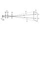
- the light receiving side lens 16 receives the reflected light R reflected from each measurement point S of the measurement target area A.
- the light receiving side optical system 17 focuses the reflected light R received by the light receiving side lens 16 in the horizontal direction X and the vertical direction Y, respectively.
- FIG. 2 is a schematic view showing a peripheral configuration including the light receiving side optical system. As shown in FIG. 2, the reflected light R reflected at each measurement point S in the measurement target area A is received by the light receiving side lens 16. The light receiving side lens 16 forms an image of each measurement point S at a predetermined position (image forming position) on the downstream side of the light receiving side lens 16.
- the light receiving side optical system 17 includes a relay lens 35 disposed at an image forming position of the light receiving side lens 16 and a condensing lens 36 disposed downstream of the relay lens 35.
- the relay lens 35 and the condensing lens 36 are provided one by one, but it goes without saying that a lens unit in which a plurality of lenses are combined may be used.
- the relay lens 35 is formed of a convex lens, and holds the image forming information of the light receiving side lens 16 at the image forming position, and substantially collimates the light flux thereafter. Have a function to transmit to In the present embodiment, the relay lens 35 is disposed at the imaging position of the light receiving side lens 16. However, the present invention is not limited to this. It may be arranged behind.
- the condenser lens 36 is a convex lens, and has the function of condensing all parallel light beams transmitted from the relay lens 35, that is, the imaging information in the horizontal direction X and the vertical direction Y toward the light receiving element 18. For this reason, the light receiving side optical system 17 can condense the imaging information of the light receiving side lens 16 on the light receiving surface 18A of the light receiving element 18 with a simple configuration in which two types of lenses are combined. It is possible to realize The light receiving element 18 is formed by a photoelectric conversion element (for example, a photodiode) that receives the reflected light R and converts it into a current, and is formed by a single element having a single pixel. Therefore, it is possible to respond to the short pulse laser beam L.
- a photoelectric conversion element for example, a photodiode
- the light receiving element 18 receives the reflected light R collected by the light receiving side optical system 17 and outputs a reception signal based on the laser light L contained in the received reflected light R.
- the amplifier circuit 19 amplifies the reception signal output from the light receiving element 18 as a voltage signal. Since the reception signal output from the light receiving element 18 is a weak current signal, the amplifier circuit 19 converts the current signal into a voltage signal and outputs the voltage signal to the distance calculation unit 20.
- the light receiving element 18 and the amplifier circuit 19 are provided to constitute a light receiving unit.
- the distance calculation unit 20 calculates distance information of the measurement point S of the measurement target area A based on the reception signal amplified by the amplifier circuit 19.
- the distance calculation unit 20 receives the pulse-like light emission synchronization signal transmitted from the light source control unit 30 and the reception signal transmitted from the amplifier circuit 19, and the measurement point S of the measurement target area A where the laser light L is irradiated. The distance to the point is calculated, and the distance information is transmitted to the information generation unit 21.
- the distance calculation unit 20 measures the time from the emission of the laser light L to the reception of the reflected light R based on the light emission synchronization signal and the reception signal, and the laser based on the measurement time. The distance to the measurement point S which reflected the light L is calculated.
- the distance calculation unit 20 may transmit the light reception intensity included in the reception signal to the information generation unit 21 in association with the distance information as well as the distance information.
- the information generation unit 21 generates three-dimensional information of the measurement target area A based on the distance information calculated by the distance calculation unit 20 and the position information of the measurement point S.
- the information generation unit 21 acquires coordinate information at the measurement point S based on distance information to the measurement point S and position information of the measurement point S in the horizontal direction X and vertical direction Y, and exists in the measurement target area A.
- Three-dimensional information of the measurement target area A is generated from the coordinate information distribution of the plurality of measurement points S.
- the information generation unit 21 acquires the mirror angles (light transmission control angles) of the galvano mirrors 14a and 15a related to the measurement point S transmitted from the scanner control unit 31, and the horizontal direction X of the measurement point S is acquired based on this mirror angle. And calculate position information in the vertical direction Y.
- the three-dimensional information of the measurement target area A generated by the information generation unit 21 is transmitted to an external device 25 (for example, a computer of a vehicle or the like) in a wired or wireless manner, and is used by the external device 25.
- an external device 25 for example, a computer of a vehicle or the like
- the condensing lens 36 combines all the image forming information of the light receiving side lens 16 transmitted from the relay lens 35 on the light receiving surface 18 A of the light receiving element 18 formed of a single element. Collect light. Therefore, the reflected light R from any measurement point S of the measurement target area A is focused on the light receiving surface 18A of the light receiving element 18, so that the light receiving element 18 constantly detects the entire measurement target area A It can be put into view. Therefore, the reflected light from the measurement target area A can be treated as single information.
- a plurality of light receiving elements are arranged and arranged, and an addition circuit for adding received signals from these light receiving elements is not necessary, and simplification of the circuit configuration can be realized.
- the light receiving element 18 is formed of a single element composed of a single pixel, the miniaturization of the light receiving element 18 can be realized, and hence the miniaturization of the laser radar device 1 can be realized.
- a long light receiving element array in which long light receiving elements described in Japanese Patent No. 5602225 are arranged in an array in a direction orthogonal to the long direction of the light receiving element and the reception signal of each long light receiving element are added
- an adding circuit By providing an adding circuit, a scanless on the light receiving side is realized while securing a wide two-dimensional field of view.
- the elongated light receiving elements in an array in the direction orthogonal to the longitudinal direction of the light receiving elements, the elongated light receiving element array is enlarged, which goes against the purpose of downsizing the laser radar device. There is a fear.
- the laser radar device 1 is provided with the light receiving side optical system 17 so that the reflected light from any measurement point S of the measurement target area A is provided on the light receiving surface 18A of the light receiving element 18
- the light receiving element 18 can always keep the entire area A to be measured within the sensor field of view. Therefore, the reflected light from the measurement target area A can be treated as single information, and miniaturization can be realized.
- the light receiving element 18 having a single pixel is disposed at the image forming position of the light receiving side lens 16.
- the area of the light receiving surface 18A of the light receiving element 18 is extremely small compared to the area of the image forming information at the image forming position of the light receiving side lens 16. I can not do it.
- a light receiving element consisting of a single element having a light receiving surface equal to or greater than the imaging information at the imaging position of the light receiving side lens 16 is required.
- the pixel size is increased, there is a problem that the responsiveness as a light receiving element (photodiode) is reduced.
- the light receiving side optical system 17 includes a relay lens 35 disposed at an image forming position of the light receiving side lens 16 and a condenser lens 36 disposed downstream of the relay lens 35.
- the condensing lens 36 responds to the light receiving surface 18 A of the light receiving element 18 formed of a single element, by focusing all the image forming information of the light receiving side lens 16 transmitted from the relay lens 35. It is possible to cover information of the entire field of view of the light receiving side lens 16 regardless of the pixel shape of the light receiving element 18 without deterioration. For this reason, the light receiving element 18 can be configured as a sensor of a rectangular, square or circular single element, and the selection range of the light receiving element can be widened.
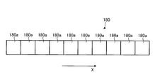
- FIGS. 3A and 3B show a modification of the light receiving element.
- the light receiving element 18 is formed by a single element having a single pixel, but as shown in FIG. 3-1, for example, a single pixel 180a may be in a predetermined direction (for example, a horizontal direction). It is also possible to use a line-shaped light receiving element (line sensor) 180 formed in line with X).
- the pixels 180a for collecting the reflected light can be used as the light receiving elements. According to this, the reflected light can be reliably received by the light receiving element, and the measurement quality can be secured.
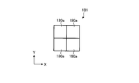
- the linear light receiving element (line sensor) 180 as shown in FIG. 3-2, a plurality of (for example, two) single pixels 180a are formed in the horizontal direction X and the vertical direction Y, respectively.
- the light receiving element group 181 may be used.
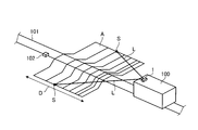
- Fig. 4-1 is a perspective view showing a configuration in which a laser radar device is mounted on a train traveling on a track
- Fig. 4-2 is a side showing a configuration in which a laser radar device is mounted on a train traveling on a track FIG.
- the laser radar device 1 is mounted on a train (running body) 100.
- the train 100 travels on the track 101, and may be configured to be driven by a driver's operation or to be automatically driven by a computer.
- the laser radar device 1 is provided on the upper front side of the train 100, and monitors a measurement target area A set forward in the traveling direction of the train 100. As described above, the laser radar device 1 does not have the scanner on the reception side, and therefore, the laser radar device 1 can be miniaturized. Therefore, in the train 100 on which the laser radar device 1 is mounted, the influence of the reduction of free space in the train 100 or the protrusion to the outside of the train 100 due to the layout of the laser radar device 1 is minimized. Can.
- the measurement target area A is set as a traveling road surface ahead in the traveling direction including the track 101 over a predetermined distance D (for example, 300 to 500 m) from the train 100, and the measurement target area A is It is updated at any time as the train 100 travels.
- the laser radar device 1 scans and irradiates the laser light L toward the measurement target area A, and generates three-dimensional information of the measurement target area A based on distance information and position information of each measurement point S.
- the train 100 is not shown, but a computer for acquiring three-dimensional information of the measurement area A output from the laser radar device 1 as the external device 25 (FIG. 1), and this computer based on the three-dimensional information And a display for displaying the shape of the drawn measurement target area A.
- These computers and displays are disposed in the cab of the train 100.
- the three-dimensional information generated by the laser radar device 1 is output to the computer of the train 100 at any time and displayed on the display via the computer. Therefore, for example, even when there is an obstacle 102 on the line 101, the display of the area to be measured A including the obstacle 102 is displayed on the display, thus providing driving assistance to the driver. can do.
- the shape change in the direction of movement in the measurement target area A exceeds a predetermined threshold, a warning alert is issued on the assumption that the obstacle 102 is likely to be present. It may be configured to inform.
- FIG. 5 is a perspective view showing a configuration in which a laser radar device is mounted on a vehicle.
- the laser radar device 1 is mounted on a vehicle (running body) 150.
- the vehicle 150 travels freely on the road surface, and may be configured to be driven by the driver's steering or to be automatically driven by a computer.
- the laser radar device 1 is provided on the front upper portion of the vehicle 150, and monitors the measurement target area A set on the terrain 200 in front of the traveling direction of the vehicle 150. As described above, the laser radar device 1 does not have the scanner on the reception side, and therefore, the laser radar device 1 can be miniaturized. For this reason, the vehicle 150 mounted with the laser radar device 1 minimizes the reduction of free space in the vehicle 150 or the influence of the protruding portion to the outside of the vehicle 150 due to the layout of the laser radar device 1. Can.
- the measurement target area A is set on the surface of the topography 200 ahead in the traveling direction over a predetermined distance D (for example, 100 m) from the vehicle 150. Updated accordingly.
- the laser radar device 1 scans and irradiates the laser light L toward the measurement target area A, and based on the distance information and position information of each measurement point S, three-dimensional information of the measurement target area A (terrain 200) Generate In FIG. 5, the topography 200 is described as including a large raised portion 200A and a small flat portion 200B.
- the vehicle 150 is provided with the navigation apparatus which performs the route guidance of this vehicle 150 as the external apparatus 25 (FIG. 1).
- the navigation device includes a control unit that controls the entire navigation device, and a display that displays a route (map information), and three-dimensional information of the measurement target area A is output to the control unit.
- the navigation apparatus sets a path 201 passing through the flat portion 200B having a small relief, based on the three-dimensional information of the measurement target area A, avoiding the crest portion 200A having a large relief. According to this configuration, even when traveling on a landform 200 with severe undulations, it is possible to travel on the route 201 including the flat portion 200B as much as possible, and driving assistance to the driver can be realized.
- safe automatic driving can be realized by traveling on the route 201 including the flat portion 200B as much as possible based on the three-dimensional information generated by the laser radar device 1.
- the composition which carries laser radar device 1 in the run object of train 100 or vehicles 150 if it is the run object which carries out self-propelled, it will not restrict to these.
- the laser radar device 1 is mounted on the traveling body, but, for example, the measurement target area A is installed on a pillar standing by the side of intersections or crossings where the measurement target area A is set.
- the configuration may be such that three-dimensional information of the measurement target area A is generated by receiving the reflected light R of a guardrail, a stationary object such as a tree, etc.).
- the laser radar device 1 includes the laser light source 11, the light transmitting side lens 12 for forming the laser light L emitted from the laser light source 11 into a point, and the point
- the scanner 13 irradiates the laser beam L while scanning in the horizontal direction X and the vertical direction Y of the measurement target area A, the light receiving side lens 16 receives the reflected light R reflected from the measurement target area A, and the light receiving A light receiving side optical system 17 for collecting the reflected light R received by the side lens 16 in the horizontal direction X and a vertical direction Y, and a light receiving element 18 for receiving the reflected light R collected by the light receiving side optical system 17
- the information generation unit 21 that generates three-dimensional information of the measurement target area A based on the reception signal output from the light reception element 18, thereby achieving downsizing of the light reception element 18 and receiving the entire measurement target area A.
- Can be accommodated in the sensor field of view of the device 18 can be realized scanless the light-receiving side with a simple
- the light receiving element 18 is configured of a single element having a single pixel, the entire measurement target area A can be included in the sensor field of view of the single element. For this reason, the addition circuit which adds the reception signal of the light receiving element 18 becomes unnecessary, and simplification of a circuit structure can be implement
- the light receiving side optical system 17 is disposed at the image forming position of the light receiving side lens 16, and relay lens 35 for transmitting while holding the image forming information at the image forming position, and the relay lens Since the collimated light beam transmitted from the light source 35 is provided with a condenser lens 36 for condensing the collimated light flux transmitted from the light source 35 toward the light receiving element 18, the imaging information of the light receiving side lens 16 is received by the light receiving element The light can be collected on the light receiving surface 18A.
- the information generation unit 21 determines the distance to the measurement point S of the measurement target area A acquired from the light round trip time from the irradiation of the laser light L to the light reception by the light receiving element 18. To generate three-dimensional information of the measurement area A from the information and each position information of the measurement point S in the horizontal direction X and the vertical direction Y acquired based on the mirror angle of the scanner 13 at the time of irradiating the laser light L With the field-of-view scanning on the light receiving side, acquisition of spatial position coordinates of the received signal becomes unnecessary, and the load of signal processing for generating three-dimensional information can be reduced.
- the above-described laser radar device 1 is mounted on the train 100 or the vehicle 150, three-dimensional information of the traveling route of the train 100 or the vehicle 150 can always be acquired. It can be carried out.
Landscapes
- Physics & Mathematics (AREA)
- Engineering & Computer Science (AREA)
- General Physics & Mathematics (AREA)
- Radar, Positioning & Navigation (AREA)
- Remote Sensing (AREA)
- Computer Networks & Wireless Communication (AREA)
- Electromagnetism (AREA)
- Optics & Photonics (AREA)
- Mechanical Engineering (AREA)
- Health & Medical Sciences (AREA)
- Biomedical Technology (AREA)
- General Health & Medical Sciences (AREA)
- Optical Radar Systems And Details Thereof (AREA)
- Measurement Of Optical Distance (AREA)
- Mechanical Optical Scanning Systems (AREA)
- Length Measuring Devices By Optical Means (AREA)
Priority Applications (4)
| Application Number | Priority Date | Filing Date | Title |
|---|---|---|---|
| EP15886490.0A EP3252497A4 (en) | 2015-03-23 | 2015-11-19 | Laser radar device and traveling body |
| CN201580076971.7A CN107407722B (zh) | 2015-03-23 | 2015-11-19 | 激光雷达装置以及行驶体 |
| US15/553,247 US10534085B2 (en) | 2015-03-23 | 2015-11-19 | Laser radar device and traveling body |
| SG11201706757WA SG11201706757WA (en) | 2015-03-23 | 2015-11-19 | Laser radar device and traveling body |
Applications Claiming Priority (2)
| Application Number | Priority Date | Filing Date | Title |
|---|---|---|---|
| JP2015-060070 | 2015-03-23 | ||
| JP2015060070A JP6522383B2 (ja) | 2015-03-23 | 2015-03-23 | レーザレーダ装置及び走行体 |
Publications (1)
| Publication Number | Publication Date |
|---|---|
| WO2016151938A1 true WO2016151938A1 (ja) | 2016-09-29 |
Family
ID=56977945
Family Applications (1)
| Application Number | Title | Priority Date | Filing Date |
|---|---|---|---|
| PCT/JP2015/082562 WO2016151938A1 (ja) | 2015-03-23 | 2015-11-19 | レーザレーダ装置及び走行体 |
Country Status (6)
Cited By (1)
| Publication number | Priority date | Publication date | Assignee | Title |
|---|---|---|---|---|
| CN111562587A (zh) * | 2019-02-14 | 2020-08-21 | 宁波舜宇车载光学技术有限公司 | 雷达装置及其发射端 |
Families Citing this family (21)
| Publication number | Priority date | Publication date | Assignee | Title |
|---|---|---|---|---|
| CA2892952C (en) | 2015-01-19 | 2019-10-15 | Tetra Tech, Inc. | Protective shroud |
| US10349491B2 (en) | 2015-01-19 | 2019-07-09 | Tetra Tech, Inc. | Light emission power control apparatus and method |
| US9849895B2 (en) | 2015-01-19 | 2017-12-26 | Tetra Tech, Inc. | Sensor synchronization apparatus and method |
| CA2892885C (en) | 2015-02-20 | 2020-07-28 | Tetra Tech, Inc. | 3d track assessment system and method |
| KR101877388B1 (ko) * | 2016-07-21 | 2018-07-11 | 엘지전자 주식회사 | 차량용 라이다 장치 |
| JP7043738B2 (ja) * | 2017-04-20 | 2022-03-30 | 株式会社Ihi | 対象物検知システム |
| CN111819462B (zh) * | 2018-03-08 | 2024-04-16 | 松下知识产权经营株式会社 | 激光雷达 |
| CN108427933B (zh) * | 2018-03-23 | 2024-01-05 | 王雪燕 | 一种用于激光清障的识别系统及识别方法 |
| JP2019191126A (ja) * | 2018-04-27 | 2019-10-31 | シャープ株式会社 | 光レーダ装置 |
| CN110456327B (zh) * | 2018-05-08 | 2024-08-02 | 探维科技(北京)有限公司 | 激光雷达接收装置及激光雷达系统 |
| US10807623B2 (en) | 2018-06-01 | 2020-10-20 | Tetra Tech, Inc. | Apparatus and method for gathering data from sensors oriented at an oblique angle relative to a railway track |
| US10730538B2 (en) | 2018-06-01 | 2020-08-04 | Tetra Tech, Inc. | Apparatus and method for calculating plate cut and rail seat abrasion based on measurements only of rail head elevation and crosstie surface elevation |
| US10625760B2 (en) | 2018-06-01 | 2020-04-21 | Tetra Tech, Inc. | Apparatus and method for calculating wooden crosstie plate cut measurements and rail seat abrasion measurements based on rail head height |
| US11377130B2 (en) | 2018-06-01 | 2022-07-05 | Tetra Tech, Inc. | Autonomous track assessment system |
| WO2019241396A1 (en) | 2018-06-15 | 2019-12-19 | Innovusion Ireland Limited | Lidar systems and methods for focusing on ranges of interest |
| US11604260B2 (en) * | 2018-11-19 | 2023-03-14 | Baidu Usa Llc | LIDAR device with polygon-shape mirror and prism for autonomous driving vehicles |
| EP3969939A4 (en) | 2019-05-16 | 2023-06-07 | Tetra Tech, Inc. | SYSTEM AND METHOD FOR GENERATION AND INTERPRETATION OF POINT CLOUDS OF A RAILWAY CORRIDOR ALONG A STUDY ROUTE |
| JP2020187079A (ja) * | 2019-05-17 | 2020-11-19 | 三菱重工業株式会社 | レーザレーダ装置及び走行体 |
| CN112585488B (zh) * | 2019-07-29 | 2023-08-04 | 深圳市速腾聚创科技有限公司 | 接收光学系统、激光接收模组、激光雷达和光调方法 |
| CN110988858B (zh) * | 2019-11-11 | 2021-12-07 | 西安空间无线电技术研究所 | 一种双波束微波着陆雷达高精度测距方法及系统 |
| CN113030912B (zh) * | 2019-12-09 | 2024-05-28 | 觉芯电子(无锡)有限公司 | 一种基于扫描振镜的激光雷达系统 |
Citations (5)
| Publication number | Priority date | Publication date | Assignee | Title |
|---|---|---|---|---|
| JPH05107043A (ja) * | 1991-10-15 | 1993-04-27 | Nec Corp | 外観検査装置 |
| JPH06258040A (ja) * | 1993-03-02 | 1994-09-16 | S K S Kk | レーザー変位計 |
| JPH09113234A (ja) * | 1995-10-19 | 1997-05-02 | Matsushita Electric Ind Co Ltd | 2次元形状計測センサー |
| JP2005055196A (ja) * | 2003-08-05 | 2005-03-03 | Olympus Corp | 基板検査方法及びその装置 |
| JP2008026243A (ja) * | 2006-07-25 | 2008-02-07 | Konica Minolta Sensing Inc | 三次元形状測定システム、三次元形状測定方法 |
Family Cites Families (13)
| Publication number | Priority date | Publication date | Assignee | Title |
|---|---|---|---|---|
| JPH01121782A (ja) * | 1987-11-05 | 1989-05-15 | Mitsubishi Electric Corp | 受光装置 |
| JP2910452B2 (ja) * | 1992-10-26 | 1999-06-23 | 三菱電機株式会社 | レーザ測距装置 |
| US5805275A (en) * | 1993-04-08 | 1998-09-08 | Kollmorgen Corporation | Scanning optical rangefinder |
| JPH1164518A (ja) * | 1997-08-12 | 1999-03-05 | Mitsubishi Electric Corp | 車両用光レーダ装置 |
| JP2002243543A (ja) * | 2001-02-19 | 2002-08-28 | Keyence Corp | 光電センサ |
| JP2003060213A (ja) * | 2001-08-16 | 2003-02-28 | Matsusada Precision Kk | 大口径広角高速受光装置 |
| US6879419B2 (en) * | 2002-12-05 | 2005-04-12 | Northrop Grumman Corporation | Laser scanner with peripheral scanning capability |
| DE102005049471B4 (de) | 2005-10-13 | 2007-09-13 | Ingenieurbüro Spies GbR (vertretungsberechtigte Gesellschafter: Hans Spies, Martin Spies, 86558 Hohenwart) | Entfernungssensor mit Einzelflächenabtastung |
| JP2009267314A (ja) * | 2008-04-30 | 2009-11-12 | Toyota Central R&D Labs Inc | 受光装置 |
| CN101430377B (zh) * | 2008-11-18 | 2011-06-22 | 北京航空航天大学 | 基于apd阵列的非扫描3d成像激光雷达光学系统 |
| US9007600B2 (en) | 2010-05-07 | 2015-04-14 | Mitsubishi Electric Corporation | Laser radar system |
| JP2014006110A (ja) * | 2012-06-22 | 2014-01-16 | Konica Minolta Inc | レーザレーダ |
| DE102013215627A1 (de) * | 2013-08-08 | 2015-02-12 | Robert Bosch Gmbh | Lichtdetektionsvorrichtung und Steuerverfahren |
-
2015
- 2015-03-23 JP JP2015060070A patent/JP6522383B2/ja not_active Expired - Fee Related
- 2015-11-19 SG SG11201706757WA patent/SG11201706757WA/en unknown
- 2015-11-19 WO PCT/JP2015/082562 patent/WO2016151938A1/ja active Application Filing
- 2015-11-19 EP EP15886490.0A patent/EP3252497A4/en not_active Withdrawn
- 2015-11-19 US US15/553,247 patent/US10534085B2/en not_active Expired - Fee Related
- 2015-11-19 CN CN201580076971.7A patent/CN107407722B/zh not_active Expired - Fee Related
Patent Citations (5)
| Publication number | Priority date | Publication date | Assignee | Title |
|---|---|---|---|---|
| JPH05107043A (ja) * | 1991-10-15 | 1993-04-27 | Nec Corp | 外観検査装置 |
| JPH06258040A (ja) * | 1993-03-02 | 1994-09-16 | S K S Kk | レーザー変位計 |
| JPH09113234A (ja) * | 1995-10-19 | 1997-05-02 | Matsushita Electric Ind Co Ltd | 2次元形状計測センサー |
| JP2005055196A (ja) * | 2003-08-05 | 2005-03-03 | Olympus Corp | 基板検査方法及びその装置 |
| JP2008026243A (ja) * | 2006-07-25 | 2008-02-07 | Konica Minolta Sensing Inc | 三次元形状測定システム、三次元形状測定方法 |
Non-Patent Citations (1)
| Title |
|---|
| See also references of EP3252497A4 * |
Cited By (2)
| Publication number | Priority date | Publication date | Assignee | Title |
|---|---|---|---|---|
| CN111562587A (zh) * | 2019-02-14 | 2020-08-21 | 宁波舜宇车载光学技术有限公司 | 雷达装置及其发射端 |
| CN111562587B (zh) * | 2019-02-14 | 2023-12-05 | 宁波舜宇车载光学技术有限公司 | 雷达装置及其发射端 |
Also Published As
| Publication number | Publication date |
|---|---|
| US10534085B2 (en) | 2020-01-14 |
| EP3252497A4 (en) | 2018-10-10 |
| CN107407722B (zh) | 2020-07-28 |
| EP3252497A1 (en) | 2017-12-06 |
| CN107407722A (zh) | 2017-11-28 |
| SG11201706757WA (en) | 2017-09-28 |
| JP6522383B2 (ja) | 2019-05-29 |
| US20180038957A1 (en) | 2018-02-08 |
| JP2016180623A (ja) | 2016-10-13 |
Similar Documents
| Publication | Publication Date | Title |
|---|---|---|
| JP6522383B2 (ja) | レーザレーダ装置及び走行体 | |
| JP6522384B2 (ja) | レーザレーダ装置及び走行体 | |
| WO2017145406A1 (ja) | レーザレーダ装置及び走行体 | |
| JP6387407B2 (ja) | 周辺検知システム | |
| US20220413102A1 (en) | Lidar systems and methods for vehicle corner mount | |
| US11614521B2 (en) | LiDAR scanner with pivot prism and mirror | |
| JP4960599B2 (ja) | 衝突防止装置及び衝突防止装置搭載車両 | |
| US11871130B2 (en) | Compact perception device | |
| US11768294B2 (en) | Compact lidar systems for vehicle contour fitting | |
| WO2023220316A1 (en) | Dual emitting co-axial lidar system with zero blind zone | |
| US11624806B2 (en) | Systems and apparatuses for mitigating LiDAR noise, vibration, and harshness | |
| US20230366984A1 (en) | Dual emitting co-axial lidar system with zero blind zone | |
| CN117813525A (zh) | 用于车辆轮廓拟合的紧凑型LiDAR系统 | |
| WO2023283205A1 (en) | Compact lidar systems for vehicle contour fitting | |
| CN117178199A (zh) | 具有高分辨率和超宽视场的紧凑型光检测和测距设计 | |
| CN120390889A (zh) | 用于激光雷达生产的探测器对准方法 | |
| WO2025116877A2 (en) | Stray light filter structures for lidar detector array | |
| WO2022272144A1 (en) | Lidar systems and methods for vehicle corner mount | |
| WO2022241060A1 (en) | Systems and apparatuses for mitigating lidar noise, vibration, and harshness | |
| CN118235061A (zh) | 用于检测盲点区域中的物体的紧凑型LiDAR系统 | |
| CN118901027A (zh) | 紧凑型感知装置 | |
| CN120077295A (zh) | 基于二维发射器阵列的激光雷达 |
Legal Events
| Date | Code | Title | Description |
|---|---|---|---|
| 121 | Ep: the epo has been informed by wipo that ep was designated in this application |
Ref document number: 15886490 Country of ref document: EP Kind code of ref document: A1 |
|
| REEP | Request for entry into the european phase |
Ref document number: 2015886490 Country of ref document: EP |
|
| WWE | Wipo information: entry into national phase |
Ref document number: 11201706757W Country of ref document: SG |
|
| WWE | Wipo information: entry into national phase |
Ref document number: 15553247 Country of ref document: US |
|
| NENP | Non-entry into the national phase |
Ref country code: DE |