WO2016148116A1 - 工作機械及びこの工作機械の制御装置 - Google Patents
工作機械及びこの工作機械の制御装置 Download PDFInfo
- Publication number
- WO2016148116A1 WO2016148116A1 PCT/JP2016/058055 JP2016058055W WO2016148116A1 WO 2016148116 A1 WO2016148116 A1 WO 2016148116A1 JP 2016058055 W JP2016058055 W JP 2016058055W WO 2016148116 A1 WO2016148116 A1 WO 2016148116A1
- Authority
- WO
- WIPO (PCT)
- Prior art keywords
- workpiece
- tool
- rotation
- cutting tool
- machine tool
- Prior art date
- Legal status (The legal status is an assumption and is not a legal conclusion. Google has not performed a legal analysis and makes no representation as to the accuracy of the status listed.)
- Ceased
Links
Images




Classifications
-
- B—PERFORMING OPERATIONS; TRANSPORTING
- B23—MACHINE TOOLS; METAL-WORKING NOT OTHERWISE PROVIDED FOR
- B23B—TURNING; BORING
- B23B1/00—Methods for turning or working essentially requiring the use of turning-machines; Use of auxiliary equipment in connection with such methods
-
- B—PERFORMING OPERATIONS; TRANSPORTING
- B23—MACHINE TOOLS; METAL-WORKING NOT OTHERWISE PROVIDED FOR
- B23Q—DETAILS, COMPONENTS, OR ACCESSORIES FOR MACHINE TOOLS, e.g. ARRANGEMENTS FOR COPYING OR CONTROLLING; MACHINE TOOLS IN GENERAL CHARACTERISED BY THE CONSTRUCTION OF PARTICULAR DETAILS OR COMPONENTS; COMBINATIONS OR ASSOCIATIONS OF METAL-WORKING MACHINES, NOT DIRECTED TO A PARTICULAR RESULT
- B23Q15/00—Automatic control or regulation of feed movement, cutting velocity or position of tool or work
- B23Q15/007—Automatic control or regulation of feed movement, cutting velocity or position of tool or work while the tool acts upon the workpiece
- B23Q15/013—Control or regulation of feed movement
-
- G—PHYSICS
- G05—CONTROLLING; REGULATING
- G05B—CONTROL OR REGULATING SYSTEMS IN GENERAL; FUNCTIONAL ELEMENTS OF SUCH SYSTEMS; MONITORING OR TESTING ARRANGEMENTS FOR SUCH SYSTEMS OR ELEMENTS
- G05B19/00—Program-control systems
- G05B19/02—Program-control systems electric
- G05B19/18—Numerical control [NC], i.e. automatically operating machines, in particular machine tools, e.g. in a manufacturing environment, so as to execute positioning, movement or co-ordinated operations by means of program data in numerical form
- G05B19/4093—Numerical control [NC], i.e. automatically operating machines, in particular machine tools, e.g. in a manufacturing environment, so as to execute positioning, movement or co-ordinated operations by means of program data in numerical form characterised by part programming, e.g. entry of geometrical information as taken from a technical drawing, combining this with machining and material information to obtain control information, named part program, for the NC machine
Definitions
- the present invention relates to a machine tool that processes a workpiece while sequentially cutting chips at the time of cutting, and a control device for the machine tool.
- a workpiece holding means for holding a workpiece for holding a workpiece
- a tool rest for holding a cutting tool for cutting the workpiece
- a relative movement of the workpiece holding means and the tool rest to fix the cutting tool to the workpiece.
- the workpiece holding means and the tool post relatively vibrate so that the cutting tool is fed in the machining feed direction while reciprocatingly vibrating along the machining feed direction.
- a machine tool including a vibrating unit that rotates and a rotating unit that relatively rotates the workpiece and the cutting tool is known (see, for example, Patent Document 1).
- the machine tool control device drives and controls the rotation unit, the feeding unit, and the vibration unit, and performs a relative rotation between the workpiece and the cutting tool, and the processing feed direction of the cutting tool with respect to the workpiece.
- the machine tool is caused to perform machining of the workpiece by the feeding operation accompanied with the reciprocating vibration.
- the cutting tool is reciprocally oscillated while performing the relative rotation based on a command from the NC.
- the position of the reciprocating vibration of the cutting tool and the rotation angle of the relative rotation by the rotating means are There was a problem that a gap occurred between them.
- the present invention solves the problems of the prior art as described above, that is, the object of the present invention is to feed the cutting tool in the machining feed direction while reciprocating vibration along the machining feed direction, By correcting the relative rotation by the rotating means and the reciprocating vibration of the vibrating means to be a predetermined value, and providing a machine tool capable of reliably cutting chips and a control device for this machine tool. is there.
- a workpiece holding means for holding a workpiece, a tool post for holding a cutting tool for cutting the workpiece, and cutting with respect to the workpiece by relative movement of the workpiece holding means and the tool rest.
- a feed means for feeding the tool in a predetermined machining feed direction; a vibrating means for relatively vibrating the work holding means and the tool post; and a rotating means for relatively rotating the work and the cutting tool.
- a machine tool for performing workpiece machining by relative rotation between the workpiece and the cutting tool and a feed operation involving the reciprocating vibration of the cutting tool in the machining feed direction with respect to the workpiece The rotation angle of the relative rotation or the rotation angle of the relative rotation is determined using a predetermined timing based on a rotation angle of the rotation or a command for moving the work holding means or the tool post to a predetermined coordinate position.
- the above-described problem is solved by executing the feeding operation with a correcting means for correcting the rotational speed or the command.
- the “predetermined value” refers to a value determined by a control command before being detected by the position detecting means.
- the position detection unit may calculate the value of the rotation angle or the value of the coordinate position a plurality of times during one rotation of the relative rotation. By detecting this, the above-described problem is further solved.
- the position detection unit detects the rotation angle of the main shaft provided with the work holding unit.
- the correction unit is configured to perform vibration timing by the vibration unit in a cycle unit that can be commanded by the vibration unit.
- the correction means increases or decreases the number of rotations of the relative rotation, thereby causing the above-described problem. Is a further solution.
- a work holding means for holding a work
- a tool post for holding a cutting tool for cutting the work, and a cutting operation performed on the work by relative movement of the work holding means and the tool post.
- a feed means for feeding the tool in a predetermined machining feed direction; a vibrating means for relatively vibrating the work holding means and the tool post; and a rotating means for relatively rotating the work and the cutting tool.
- the machine tool is processed by the relative rotation between the workpiece and the cutting tool and the feed operation with the reciprocating vibration in the machining feed direction of the cutting tool with respect to the workpiece.
- a control device for a machine tool to be operated wherein the predetermined rotation is based on a rotation angle of the relative rotation or a command for moving the work holding means or the tool post to a predetermined coordinate position.
- the relative rotation between the workpiece and the cutting tool and the reciprocating vibration of the vibration means are predetermined. It can correct
- this position difference is detected in order to detect the position difference between the detected position information and the predicted position information at a plurality of timings. Can be kept within a predetermined value with higher accuracy.
- the rotation angle of the spindle is easily detected at a predetermined timing. Compared with the case where the position of the reciprocating vibration is detected, the configuration can be simplified.
- the command is issued while the relative rotational speed (rotation speed) between the workpiece and the cutting tool is maintained. Since the timing of the reciprocating vibration is changed in units of periods that can be detected, the position difference between the detected position information and the predicted position information can be accurately stored within a predetermined amount.
- the relative rotational speed between the workpiece and the cutting tool while maintaining the vibration timing by the vibration means in addition to the effects of the inventions according to claims 1 to 3, the relative rotational speed between the workpiece and the cutting tool while maintaining the vibration timing by the vibration means. Therefore, the positional difference between the detected position information and the predicted position information can be accurately stored within a predetermined amount.
- the machine tool control device of the invention of claim 6 can obtain the same effect as the effect of the invention of claim 1.
- FIG. 7 is a chart showing reference spindle rotation angle determination processing in FIG. 6.
- FIG. 7 is a chart showing the synchronization process A in FIG. 6.
- FIG. 7 is a chart showing the synchronization process B of FIG. 6.
- the machine tool of the present invention and the control device for the machine tool use the rotation angle of the relative rotation or the rotation angle of the relative rotation using the predetermined timing based on the command to move the work holding means or the tool post to the predetermined coordinate position.
- a correction unit that corrects the command by performing a feeding operation with a correction unit that corrects the command, the relative rotation between the workpiece and the cutting tool and the reciprocating vibration of the vibration unit are corrected to be a predetermined value, and the chip is surely obtained. Any specific embodiment may be used as long as it can be divided.
- FIG. 1 is a diagram schematically illustrating a machine tool 100 including a control device C according to an embodiment of the present invention.
- the machine tool 100 includes a main shaft 110 as a rotating means and a cutting tool base 130A as a tool rest.
- a chuck 120 as a work holding means is provided at the tip of the main shaft 110.
- the workpiece W is held on the spindle 110 via the chuck 120.
- the main shaft 110 is supported by the main shaft 110A so as to be rotationally driven by the power of a main shaft motor (not shown).
- the headstock 110A is mounted on the bed side of the machine tool 100 so as to be movable in the Z-axis direction, which is the axial direction of the main shaft 110, by the Z-axis direction feed mechanism 160.
- the spindle 110 is moved in the Z-axis direction by the Z-axis direction feed mechanism 160 via the spindle stock 110A.
- the Z-axis direction feed mechanism 160 constitutes a main shaft moving mechanism that moves the main shaft 110 in the Z-axis direction.
- the Z-axis direction feed mechanism 160 includes a base 161 integrated with a fixed side of the Z-axis direction feed mechanism 160 such as the bed, and a Z-axis direction guide rail 162 provided on the base 161 and extending in the Z-axis direction. Yes.
- a Z-axis direction feed table 163 is slidably supported on the Z-axis direction guide rail 162 via a Z-axis direction guide 164.
- a mover 165a of the linear servo motor 165 is provided on the Z-axis direction feed table 163 side, and a stator 165b of the linear servo motor 165 is provided on the base 161 side.
- the headstock 110 ⁇ / b> A is mounted on the Z-axis direction feed table 163, and the Z-axis direction feed table 163 is driven to move in the Z-axis direction by driving the linear servo motor 165. As the Z-axis direction feed table 163 moves, the headstock 110A moves in the Z-axis direction, and the spindle 110 moves in the Z-axis direction.
- a cutting tool 130 such as a cutting tool for turning the workpiece W is mounted on the cutting tool base 130A.
- the cutting tool base 130A is moved to the bed side of the machine tool 100 by an X-axis direction feed mechanism 150 and a Y-axis direction feed mechanism (not shown), an X-axis direction orthogonal to the Z-axis direction, and the Z-axis direction and the X-axis direction. It is provided so as to be movable in the Y-axis direction orthogonal to.
- the X-axis direction feed mechanism 150 and the Y-axis direction feed mechanism constitute a tool post moving mechanism that moves the cutting tool base 130A in the X-axis direction and the Y-axis direction with respect to the main shaft 110.
- the X-axis direction feed mechanism 150 includes a base 151 that is integral with the fixed side of the X-axis direction feed mechanism 150, and an X-axis direction guide rail 152 that is provided on the base 151 and extends in the X-axis direction.
- An X-axis direction feed table 153 is slidably supported on the X-axis direction guide rail 152 via an X-axis direction guide 154.
- a mover 155a of the linear servo motor 155 is provided on the X-axis direction feed table 153 side, and a stator 155b of the linear servo motor 155 is provided on the base 151 side.
- the X-axis direction feed table 153 is driven to move in the X-axis direction.
- the Y-axis direction feed mechanism is the same as the X-axis direction feed mechanism 150 in which the X-axis direction feed mechanism 150 is arranged in the Y-axis direction, and therefore a detailed description of the structure is omitted.
- an X-axis direction feed mechanism 150 is mounted on the bed side via a Y-axis direction feed mechanism (not shown), and a cutting tool table 130A is mounted on the X-axis direction feed table 153.
- the cutting tool base 130A moves in the X-axis direction by the movement drive of the X-axis direction feed table 153, and the Y-axis direction feed mechanism operates in the same manner as the X-axis direction feed mechanism 150 in the Y-axis direction. To move in the Y-axis direction.
- a Y-axis direction feed mechanism (not shown) may be mounted on the bed side via the X-axis direction feed mechanism 150, and the cutting tool base 130A may be mounted on the Y-axis direction feed mechanism side. Since the structure in which the cutting tool base 130A is moved in the X-axis direction and the Y-axis direction by the X-axis direction feed mechanism 150 is conventionally known, detailed description and illustration are omitted.
- the turret moving mechanism (X-axis direction feeding mechanism 150 and Y-axis direction feeding mechanism) and the main shaft moving mechanism (Z-axis direction feeding mechanism 160) cooperate to provide an X-axis direction feeding mechanism 150 and a Y-axis direction feeding mechanism.
- the cutting tool table 130A is mounted on the cutting tool table 130A by the movement of the cutting tool table 130A in the X-axis direction and the Y-axis direction due to the movement of the main shaft table 110A (main shaft 110) in the Z-axis direction by the Z-axis direction feed mechanism 160.
- the cutting tool 130 is fed relative to the workpiece W in an arbitrary machining feed direction.
- both the headstock 110A and the cutting tool base 130A are moved.
- the headstock 110A is fixed so as not to move to the bed side of the machine tool 100, and the tool post moving mechanism.
- the cutting tool base 130A may be configured to move in the X-axis direction, the Y-axis direction, and the Z-axis direction.
- the feeding means is composed of a tool post moving mechanism that moves the cutting tool base 130A in the X-axis direction, the Y-axis direction, and the Z-axis direction, and is fixedly positioned and rotated relative to the main spindle 110.
- the cutting tool base 130A may be fixed so as not to move to the bed side of the machine tool 100, and the spindle moving mechanism may be configured to move the spindle base 110A in the X axis direction, the Y axis direction, and the Z axis direction.
- the feed means is composed of a spindle stock moving mechanism that moves the spindle stock 110A in the X-axis direction, the Y-axis direction, and the Z-axis direction.
- the rotation of the main shaft 110, the Z-axis direction feed mechanism 160, the X-axis direction feed mechanism 150, and the Y-axis direction feed mechanism are driven and controlled by a control unit C1 included in the control device C.
- the control unit C1 is set in advance so as to control the head stock 110A or the cutting tool base 130A to move in the respective directions while reciprocatingly oscillating along the corresponding moving directions using the respective feeding mechanisms as vibration means. ing.
- each feed mechanism is controlled by the control unit C ⁇ b> 1 to move the spindle 110 or the cutting tool base 130 ⁇ / b> A forward (forward) by a predetermined advance amount in one reciprocating vibration, and then move to a predetermined position.
- the cutting tool 130 is fed to the workpiece W in the Z-axis direction as the machining feed direction.
- the machine tool 100 uses the Z-axis direction feed mechanism 160, the X-axis direction feed mechanism 150, and the Y-axis direction feed mechanism to cause the cutting tool 130 to reciprocate along the machining feed direction while rotating the main shaft for one rotation, that is, The workpiece W is machined by being fed in the machining feed direction with the total amount of advance when the spindle phase is changed from 0 degree to 360 degrees as a feed amount.
- the head stock 110A (main shaft 110) or the cutting tool base 130A (cutting tool 130) moves while reciprocatingly oscillating, and the cutting tool 130 cuts the workpiece W into a predetermined shape.
- the peripheral surface of the workpiece W is cut into a sinusoidal shape as shown in FIG.
- the virtual line one-dot chain line
- the amount of change in position when the main axis phase changes from 0 degrees to 360 degrees indicates the feed amount.
- the lowest point of the trough in the phase of the workpiece circumferential surface turned by the n + 1-th rotation (where n is an integer equal to or greater than 1) (a dotted waveform that is the point most cut in the feed direction by the cutting tool 130)
- the position of the peak of the graph is the main axis phase direction (the peak of the graph) relative to the position of the lowest point of the phase trough (vertical peak of the solid line waveform graph) of the shape turned by the n-th cutting tool 130. It shifts in the horizontal axis direction).
- the cutting part at the time of the forward movement of the cutting tool 130 and the cutting part at the time of the backward movement partially overlap, and the part that has been cut at the n-th rotation is added to the n + 1-th cutting part of the work surface. So that a so-called idling operation in which the cutting tool 130 does not cut the workpiece W during vibration cutting occurs. Chips generated from the workpiece W at the time of cutting are sequentially divided by the idling motion.
- the machine tool 100 can smoothly perform the external cutting of the workpiece W while dividing the chips by the reciprocating vibration along the cutting feed direction of the cutting tool 130.
- the n + 1-th cut portion of the work peripheral surface includes a portion that has been cut at the n-th turn.
- the trajectory of the cutting tool 130 during the backward movement at the (n + 1) th rotation (n is an integer of 1 or more) of the workpiece circumferential surface reaches the trajectory of the cutting tool 130 at the nth rotation of the workpiece circumferential surface.
- the phases of the shapes turned by the cutting tool 130 in the (n + 1) th rotation and the nth rotation of the workpiece W do not have to coincide with each other (the same phase), and it is not always necessary to reverse 180 °.
- the frequency N can be 1.1, 1.25, 2.6, 3.75, or the like. It is also possible to set so that less than one vibration (0 ⁇ frequency N ⁇ 1.0) is performed by one rotation of the workpiece W. In this case, the main shaft 110 rotates one rotation or more with respect to one vibration.
- the command by the control unit C1 is performed every predetermined command time unit.
- the reciprocating vibration of the head stock 110A (main shaft 110) or the cutting tool base 130A (cutting tool 130) can be operated at a predetermined frequency based on the command time unit.
- the machine tool 100 of the present embodiment includes a spindle rotation angle encoder (not shown) as position detection means that detects a rotation angle that is a phase of the spindle 110 at a predetermined check timing based on the position of reciprocating vibration of the vibration means.
- the control unit C1 includes a correction unit that corrects the rotation of the main shaft 110 and the reciprocating vibration of the vibration unit so as to be a predetermined value.
- the control unit C1 compares the detected position information of the position detecting means with the theoretical predicted position information of the rotation angle of the main shaft 110 obtained from the rotation speed of the main shaft 110, and the position difference between the detected position information and the predicted position information is determined. In some cases, the position difference is reduced by adjusting one of the rotational speed of the main shaft 110 and the reciprocating vibration of the vibration means.
- step S11 of FIG. 6 the control unit C1 generates a command for each command time unit period as described above so as to be, for example, 14 command cycles.
- step S12 the control unit C1 initializes the variable i.
- step S13 a trigger generated for each command is waited. If there is a trigger, the process proceeds to step S14.
- step S14 the control unit C1 determines whether or not the reference spindle rotation angle is undetermined. If it is determined that it is not yet determined, the process proceeds to step S15. If it is determined that it is not yet determined, the process proceeds to step S19. . For example, even if the reference spindle rotation angle is initially determined, the reference spindle rotation angle may be replaced with a new reference spindle rotation angle including a deviation amount at the next check timing. Good.
- step S15 a reference spindle rotation angle determination process, which will be described in detail later, is performed.
- step S16 the control unit C1 outputs a command.
- step S17 the number of commands is counted, that is, the variable i is incremented by one every time it passes step S17.
- step S18 the control unit C1 determines whether or not the cutting tool 130 has reached the cutting end point. When it is determined that the cutting tool 130 has reached, the sequence is ended, and when it is determined that the cutting tool 130 has not reached, the process returns to step S13. .
- step S19 a synchronization process A or a synchronization process B, which will be described in detail later, is executed, and the process proceeds to step S16.
- step S21 of FIG. 7 the control unit C1 determines whether or not it is a predetermined check timing. If it is determined that it is the check timing, the process proceeds to step S22. If it is determined that it is not the check timing, the reference spindle rotation angle is determined. The processing sequence is terminated, and the process proceeds to step S16 in FIG.
- step S22 the control unit C1 stores the current output value of the main spindle rotation angle encoder, and sets this output value as the reference main spindle rotation angle. In order to facilitate understanding of the present invention, for example, 0 ° (360 °) is set as a reference spindle rotation angle. Then, the sequence of the reference spindle rotation angle determination process is terminated, and the process proceeds to step S16 in FIG.
- step S31 of FIG. 8 the control unit C1 determines whether or not it is a predetermined check timing. If it is determined that it is the check timing, the process proceeds to step S32. If it is determined that it is not the check timing, the sequence of the synchronization process A is determined. And the process proceeds to step S16 in FIG.
- step S32 the control unit C1 compares the current output value of the main spindle rotation angle encoder with the reference main spindle rotation angle, and determines whether or not the reciprocating vibration of the vibration means is advanced with respect to the reference main spindle rotation angle. For example, if the current output value of the main spindle rotation angle encoder is 180 ° or more and less than 360 ° (an angle in a direction delayed from 0 ° as the reference main shaft rotation angle), the reciprocating vibration of the vibration means is advanced. Determination is made and the process proceeds to step S33. Otherwise, it is determined that the reciprocating vibration of the vibration means is not advanced, and the process proceeds to step S34.
- step S33 the control unit C1 selects the previous command in the previous order and sends the same previous command to delay one command timing, thereby rotating the spindle 110 and the reciprocating vibration of the vibration means.
- the sequence of the synchronization process A is terminated, and the process proceeds to step S16 in FIG.
- step S34 the control unit C1 compares the current output value of the main spindle rotation angle encoder with the reference main spindle rotation angle, and determines whether or not the reciprocating vibration of the vibration means is delayed with respect to the reference main spindle rotation angle. For example, if the current output value of the main spindle rotation angle encoder is greater than 0 ° and less than 180 °, it is determined that the reciprocating vibration of the vibration means is delayed, and the process proceeds to step S35. It is determined that the reciprocating vibration is not delayed, the sequence of the synchronization process A is terminated, and the process proceeds to step S16 in FIG.
- step S35 the control unit C1 selects the next command in the order and skips one command, that is, skips and sends the next command to advance the timing of one command by the spindle 110. 6 and the reciprocating vibration of the vibration means are corrected to a predetermined value, the value of the variable i is increased by 1, the sequence of the synchronization process A is terminated, and the process proceeds to step S16 in FIG.
- the control unit C1 as the correction unit advances the rotation of the main shaft 110 and reciprocates the vibration unit by advancing or delaying the vibration timing by the vibration unit in a cycle unit that can be commanded by the vibration unit.
- the vibration is corrected so as to be a predetermined value.
- control unit C1 is configured to synchronize the rotation of the main shaft 110 and the reciprocating vibration of the vibration means by advancing or delaying the vibration timing by the vibration means in units of cycles that can be commanded by the vibration means.
- the increase / decrease amount of the value of the variable i in steps S33 and S35 may be two or more according to the magnitude of the difference between the current output value of the spindle rotation angle encoder and the reference spindle rotation angle.
- step S41 of FIG. 9 the control unit C1 determines whether or not it is a predetermined check timing. If it is determined that it is the check timing, the process proceeds to step S42, and if it is determined that it is not the check timing, the sequence of the synchronization process B And the process proceeds to step S16 in FIG.
- step S42 as in step S32 of the synchronization process A described above, the control unit C1 compares the current output value of the main spindle rotation angle encoder with the reference main spindle rotation angle, and the reciprocation of the vibration means with respect to the reference main spindle rotation angle. It is determined whether or not the vibration is progressing.
- step S43 the control unit C1 sets the rotational speed of the main shaft 110 so that the rotation speed of the main shaft 110 is increased to correct the rotation of the main shaft 110 and the reciprocating vibration of the vibration means to a predetermined value.
- S is increased by, for example, one rotation, the sequence of the synchronization process B is terminated, and the process proceeds to step S16 in FIG.
- step S44 as in step S34 of the synchronization process A described above, the control unit C1 compares the current output value of the main spindle rotation angle encoder with the reference main spindle rotation angle, and the reciprocation of the vibration means with respect to the reference main spindle rotation angle. Determine whether the vibration is delayed.
- step S45 the control unit C1 sets the rotational speed of the main shaft 110 so that the rotation speed of the main shaft 110 is reduced to correct the rotation of the main shaft 110 and the reciprocating vibration of the vibration means to be a predetermined value. Is reduced by, for example, one rotation, the sequence of the synchronization process B is terminated, and the process proceeds to step S16 in FIG.
- the control unit C1 as the correction unit increases or decreases the rotational speed of the main shaft 110 to set the rotation of the main shaft 110 and the reciprocating vibration of the vibration unit to predetermined values. It is comprised so that it may correct
- the increase / decrease amount of the set value S of the rotation speed of the spindle 110 in steps S43 and S45 is set to 2 rotations or more.
- the position detection unit is configured to detect the rotation angle of the main shaft 110 at a predetermined check timing based on the position of the reciprocating vibration of the vibration unit.
- the predetermined timing based on the rotation angle of the main shaft 110 is used.
- the position of the reciprocating vibration of the vibration means may be detected by Alternatively, a plurality of predetermined timings may be set within one relative rotation. For example, as shown in FIG.
- the control unit C1 as the correcting unit compares the detected position information of the position detecting unit with the predicted position information of the rotation angle of the main shaft 110 obtained from the rotation speed of the main shaft 110, and compares the detected position information with the predicted position information.
- the rotational speed of the main shaft 110 and one of the reciprocating vibrations of the vibration means are adjusted so as to reduce this positional difference, and the rotation of the main shaft 110 and the reciprocating vibration of the vibration means are synchronized. May be.
- the trajectory of the cutting tool 130 during the backward movement of the workpiece W at the (n + 1) th rotation (n is an integer of 1 or more) of the workpiece W is represented by n rotations of the workpiece W.
- control is performed so as to intersect with the trajectory of the cutting tool 130 in the eye, it may be reached without intersecting. In other words, control was performed so that the cutting part at the time of forward movement and the cutting part at the time of backward movement overlap, but the cutting part at the time of forward movement and the cutting part at the time of backward movement were controlled to contact each other. May be.
- the cutting portion at the time of backward movement of the cutting tool 130 in one vibration includes the cutting portion at the time of backward movement as a theoretical “point”, and the cutting tool 130 does not cut the workpiece W during the backward movement.
- the idle motion occurs at “points”
- chips generated from the workpiece W during cutting are sequentially divided by the idle motion (the point where the cutting portion during forward movement and the cutting portion during reverse movement contact). Is done.
Landscapes
- Engineering & Computer Science (AREA)
- Physics & Mathematics (AREA)
- Mechanical Engineering (AREA)
- Geometry (AREA)
- Human Computer Interaction (AREA)
- Manufacturing & Machinery (AREA)
- General Physics & Mathematics (AREA)
- Automation & Control Theory (AREA)
- Automatic Control Of Machine Tools (AREA)
- Turning (AREA)
- Numerical Control (AREA)
Abstract
切削工具を加工送り方向に沿った往復振動をさせながら加工送り方向に送り、回転手段による相対回転と振動手段の往復振動とを予め定めされた値となるように補正して切屑を確実に分断する工作機械及びこの工作機械の制御装置を提供すること。 ワークと切削工具との相対回転の回転角度および振動手段の往復振動の位置の一方に基づく所定のタイミングで相対回転の回転角度および往復振動の位置の他方を検出する位置検出手段と、位置検出手段の検出位置情報と振動手段の指令から得られる往復振動位置または相対回転の回転数から得られる相対回転の回転角度の予測位置情報とを比べて、検出位置情報と予測位置情報との位置差があるとき、位置差を小さくするように相対回転の回転数および往復振動の一方を調整して相対回転の回転と往復振動とを予め定められた値となるように補正する補正手段(C1)とを備えている工作機械(100)とその制御装置(C)。
Description
本発明は、切削加工時の切屑を順次分断しながらワークの加工を行う工作機械及びこの工作機械の制御装置に関する。
従来、ワークを保持するワーク保持手段と、前記ワークを切削加工する切削工具を保持する刃物台と、前記ワーク保持手段と前記刃物台との相対移動によって、前記ワークに対して前記切削工具を所定の加工送り方向に送り動作させる送り手段と、前記切削工具が前記加工送り方向に沿って往復振動しながら加工送り方向に送られるように、前記ワーク保持手段と前記刃物台とを相対的に振動させる振動手段と、前記ワークと前記切削工具を相対的に回転させる回転手段とを備えた工作機械が知られている(例えば、特許文献1参照)。
この工作機械の制御装置は、前記回転手段と、前記送り手段と、前記振動手段とを駆動制御し、前記ワークと前記切削工具との相対回転と、前記ワークに対する前記切削工具の前記加工送り方向への前記往復振動を伴う送り動作とによって前記工作機械に、前記ワークの加工を実行させる。
この工作機械の制御装置は、前記回転手段と、前記送り手段と、前記振動手段とを駆動制御し、前記ワークと前記切削工具との相対回転と、前記ワークに対する前記切削工具の前記加工送り方向への前記往復振動を伴う送り動作とによって前記工作機械に、前記ワークの加工を実行させる。
しかしながら、上述した従来の工作機械において、NCからの指令に基づいて前記相対回転させながら切削工具を往復振動させているが、切削工具の往復振動の位置と回転手段による相対回転の回転角度との間でズレが生じるという問題があった。
そこで、本発明は、前述したような従来技術の問題を解決するものであって、すなわち、本発明の目的は、切削工具を加工送り方向に沿った往復振動をさせながら加工送り方向に送り、回転手段による相対回転と振動手段の往復振動とを予め定められた値となるように補正を行い、切屑を確実に分断することが可能な工作機械及びこの工作機械の制御装置を提供することである。
本請求項1に係る発明は、ワークを保持するワーク保持手段と、前記ワークを切削加工する切削工具を保持する刃物台と、前記ワーク保持手段と刃物台との相対移動によってワークに対して切削工具を所定の加工送り方向に送り動作させる送り手段と、前記ワーク保持手段と刃物台とを相対的に振動させる振動手段と、前記ワークと切削工具とを相対的に回転させる回転手段とを備え、前記ワークと前記切削工具との相対回転と、前記ワークに対する前記切削工具の前記加工送り方向への前記往復振動を伴う送り動作とによって、ワークの加工を実行させる工作機械であって、前記相対回転の回転角度又は前記ワーク保持手段あるいは刃物台を所定の座標位置に移動させる指令に基づく所定のタイミングを用いて、前記相対回転の回転角度又は前記ワーク保持手段あるいは刃物台の座標位置を検出する位置検出手段と、該位置検出手段によって検出された回転角度の値又は座標位置の値を予め定められた値となるように、前記相対回転の回転数又は指令を補正する補正手段とを備えて前記送り動作を実行することにより、前述した課題を解決するものである。
ここで、「予め定められた値」とは、位置検出手段に検出されるより前に制御指令により定められる値をいう。
ここで、「予め定められた値」とは、位置検出手段に検出されるより前に制御指令により定められる値をいう。
本請求項2に係る発明は、請求項1に記載された工作機械の構成に加えて、前記位置検出手段が、前記相対回転の1回転中に回転角度の値又は座標位置の値を複数回検出することにより、前述した課題をさらに解決するものである。
本請求項3に係る発明は、請求項1または請求項2に記載された工作機械の構成に加えて、前記位置検出手段が、前記ワーク保持手段を備えた主軸の回転角度を検出する主軸回転角度エンコーダであることにより、前述した課題をさらに解決するものである。
本請求項4に係る発明は、請求項1乃至請求項3に記載された工作機械の構成に加えて、前記補正手段が、前記振動手段の指令が可能な周期単位で前記振動手段による振動タイミングを早めるまたは遅らせることにより、前述した課題をさらに解決するものである。
本請求項5に係る発明は、請求項1乃至請求項3に記載された工作機械の構成に加えて、前記補正手段が、前記相対回転の回転数を大きくまたは小さくすることにより、前述した課題をさらに解決するものである。
本請求項6に係る発明は、ワークを保持するワーク保持手段と、前記ワークを切削加工する切削工具を保持する刃物台と、前記ワーク保持手段と刃物台との相対移動によってワークに対して切削工具を所定の加工送り方向に送り動作させる送り手段と、前記ワーク保持手段と刃物台とを相対的に振動させる振動手段と、前記ワークと切削工具とを相対的に回転させる回転手段とを備えた工作機械に設けられ、前記ワークと前記切削工具との相対回転と、前記ワークに対する前記切削工具の加工送り方向への前記往復振動を伴う送り動作とによって、前記工作機械にワークの加工を実行させる工作機械の制御装置であって、前記相対回転の回転角度又は前記ワーク保持手段あるいは刃物台を所定の座標位置に移動させる指令に基づく所定のタイミングを用いて、前記相対回転の回転角度又は前記ワーク保持手段あるいは刃物台の座標位置を検出する位置検出手段を備え、該位置検出手段によって検出された回転角度の値又は座標位置の値を予め定められた値となるように、前記相対回転の回転数又は指令を補正する補正手段を備えて前記送り動作を実行することにより、前述した課題を解決するものである。
本請求項1に係る発明の工作機械によれば、検出位置情報と予測位置情報との位置差が小さくなるため、ワークと切削工具との相対回転と振動手段の往復振動とを予め定められた値となるように補正し、確実に切屑を分断することができる。
つまり回転手段による相対回転の回転角度と切削工具の往復振動とのズレが補正され、切屑の分断が可能になる。
さらに、所定のタイミングで位置検出手段によって検出された回転角度の値と、理論上の回転角度の値との差になる検出位置情報と予測位置情報との位置差が許容範囲を超えたときにワーク加工面上に見える筋状の外観不良を目立たなくすることができる。
つまり回転手段による相対回転の回転角度と切削工具の往復振動とのズレが補正され、切屑の分断が可能になる。
さらに、所定のタイミングで位置検出手段によって検出された回転角度の値と、理論上の回転角度の値との差になる検出位置情報と予測位置情報との位置差が許容範囲を超えたときにワーク加工面上に見える筋状の外観不良を目立たなくすることができる。
本請求項2に係る発明の工作機械によれば、請求項1に係る発明が奏する効果に加えて、複数のタイミングで検出位置情報と予測位置情報との位置差を検出するため、この位置差をより精度よく所定値内に収めることができる。
本請求項3に係る発明の工作機械によれば、請求項1または請求項2に係る発明が奏する効果に加えて、所定のタイミングで主軸の回転角度が簡単に検出されるため、振動手段の往復振動の位置を検出する場合と比べて、構成をシンプルにすることができる。
本請求項4に係る発明の工作機械によれば、請求項1乃至請求項3に係る発明が奏する効果に加えて、ワークと切削工具との相対回転速度(回転数)が維持されたままで指令が可能な周期単位で往復振動のタイミングが変更されるため、検出位置情報と予測位置情報との位置差を精度よく所定量内に収めることができる。
本請求項5に係る発明の工作機械によれば、請求項1乃至請求項3に係る発明が奏する効果に加えて、振動手段による振動タイミングが維持されたままでワークと切削工具との相対回転速度が変更されるため、検出位置情報と予測位置情報との位置差を精度よく所定量内に収めることができる。
本請求項6に係る発明の工作機械の制御装置によれば、工作機械の制御装置において、請求項1に係る発明が奏する効果と同様の効果を得ることができる。
本発明の工作機械及びこの工作機械の制御装置は、相対回転の回転角度又はワーク保持手段あるいは刃物台を所定の座標位置に移動させる指令に基づく所定のタイミングを用いて、相対回転の回転角度又はワーク保持手段あるいは刃物台の座標位置を検出する位置検出手段と、この位置検出手段によって検出された回転角度の値又は座標位置の値を予め定められた値となるように、相対回転の回転数又は指令を補正する補正手段とを備えて送り動作を実行することにより、ワークと切削工具との相対回転と振動手段の往復振動とを予め定められた値となるように補正し、確実に切屑を分断するものであれば、その具体的な実施態様は、如何なるものであっても構わない。
図1は、本発明の実施例の制御装置Cを備えた工作機械100の概略を示す図である。
工作機械100は、回転手段としての主軸110と、刃物台としての切削工具台130Aとを備えている。
主軸110の先端にはワーク保持手段としてのチャック120が設けられている。
チャック120を介して主軸110にワークWが保持される。
主軸110は、図示しない主軸モータの動力によって回転駆動されるように主軸台110Aに支持されている。
工作機械100は、回転手段としての主軸110と、刃物台としての切削工具台130Aとを備えている。
主軸110の先端にはワーク保持手段としてのチャック120が設けられている。
チャック120を介して主軸110にワークWが保持される。
主軸110は、図示しない主軸モータの動力によって回転駆動されるように主軸台110Aに支持されている。
主軸台110Aは、工作機械100のベッド側に、Z軸方向送り機構160によって主軸110の軸線方向となるZ軸方向に移動自在に搭載されている。
主軸110は、主軸台110Aを介してZ軸方向送り機構160によって、前記Z軸方向に移動する。
Z軸方向送り機構160は、主軸110をZ軸方向に移動させる主軸移動機構を構成している。
主軸110は、主軸台110Aを介してZ軸方向送り機構160によって、前記Z軸方向に移動する。
Z軸方向送り機構160は、主軸110をZ軸方向に移動させる主軸移動機構を構成している。
Z軸方向送り機構160は、前記ベッド等のZ軸方向送り機構160の固定側と一体的なベース161と、ベース161に設けられたZ軸方向に延びるZ軸方向ガイドレール162とを備えている。
Z軸方向ガイドレール162に、Z軸方向ガイド164を介してZ軸方向送りテーブル163がスライド自在に支持されている。
Z軸方向送りテーブル163側にリニアサーボモータ165の可動子165aが設けられ、ベース161側にリニアサーボモータ165の固定子165bが設けられている。
Z軸方向ガイドレール162に、Z軸方向ガイド164を介してZ軸方向送りテーブル163がスライド自在に支持されている。
Z軸方向送りテーブル163側にリニアサーボモータ165の可動子165aが設けられ、ベース161側にリニアサーボモータ165の固定子165bが設けられている。
Z軸方向送りテーブル163に主軸台110Aが搭載され、リニアサーボモータ165の駆動によってZ軸方向送りテーブル163が、Z軸方向に移動駆動される。
Z軸方向送りテーブル163の移動によって主軸台110AがZ軸方向に移動し、主軸110のZ軸方向への移動が行われる。
Z軸方向送りテーブル163の移動によって主軸台110AがZ軸方向に移動し、主軸110のZ軸方向への移動が行われる。
切削工具台130Aには、ワークWを旋削加工するバイト等の切削工具130が装着されている。
切削工具台130Aは、工作機械100のベッド側に、X軸方向送り機構150及び図示しないY軸方向送り機構によって、前記Z軸方向に直交するX軸方向と、前記Z軸方向及びX軸方向に直交するY軸方向とに移動自在に設けられている。
X軸方向送り機構150とY軸方向送り機構とによって、切削工具台130Aを主軸110に対して前記X軸方向及びY軸方向に移動させる刃物台移動機構が構成されている。
切削工具台130Aは、工作機械100のベッド側に、X軸方向送り機構150及び図示しないY軸方向送り機構によって、前記Z軸方向に直交するX軸方向と、前記Z軸方向及びX軸方向に直交するY軸方向とに移動自在に設けられている。
X軸方向送り機構150とY軸方向送り機構とによって、切削工具台130Aを主軸110に対して前記X軸方向及びY軸方向に移動させる刃物台移動機構が構成されている。
X軸方向送り機構150は、X軸方向送り機構150の固定側と一体的なベース151と、ベース151に設けられたX軸方向に延びるX軸方向ガイドレール152とを備えている。
X軸方向ガイドレール152に、X軸方向ガイド154を介してX軸方向送りテーブル153がスライド自在に支持されている。
X軸方向ガイドレール152に、X軸方向ガイド154を介してX軸方向送りテーブル153がスライド自在に支持されている。
X軸方向送りテーブル153側にリニアサーボモータ155の可動子155aが設けられ、ベース151側にリニアサーボモータ155の固定子155bが設けられている。
リニアサーボモータ155の駆動によってX軸方向送りテーブル153が、X軸方向に移動駆動される。
なおY軸方向送り機構は、X軸方向送り機構150をY軸方向に配置したものであり、X軸方向送り機構150と同様の構造であるため、構造についての詳細な説明は割愛する。
リニアサーボモータ155の駆動によってX軸方向送りテーブル153が、X軸方向に移動駆動される。
なおY軸方向送り機構は、X軸方向送り機構150をY軸方向に配置したものであり、X軸方向送り機構150と同様の構造であるため、構造についての詳細な説明は割愛する。
図1においては、図示しないY軸方向送り機構を介してX軸方向送り機構150を前記ベッド側に搭載し、X軸方向送りテーブル153に切削工具台130Aが搭載されている。
切削工具台130Aは、X軸方向送りテーブル153の移動駆動によってX軸方向に移動し、Y軸方向送り機構が、Y軸方向に対して、X軸方向送り機構150と同様の動作をすることによって、Y軸方向に移動する。
切削工具台130Aは、X軸方向送りテーブル153の移動駆動によってX軸方向に移動し、Y軸方向送り機構が、Y軸方向に対して、X軸方向送り機構150と同様の動作をすることによって、Y軸方向に移動する。
なお図示しないY軸方向送り機構を、X軸方向送り機構150を介して前記ベッド側に搭載し、Y軸方向送り機構側に切削工具台130Aを搭載してもよく、Y軸方向送り機構とX軸方向送り機構150とによって切削工具台130AをX軸方向及びY軸方向に移動させる構造は従来公知であるため、詳細な説明及び図示は割愛する。
前記刃物台移動機構(X軸方向送り機構150とY軸方向送り機構)と前記主軸移動機構(Z軸方向送り機構160)とが協動し、X軸方向送り機構150とY軸方向送り機構によるX軸方向とY軸方向への切削工具台130Aの移動と、Z軸方向送り機構160による主軸台110A(主軸110)のZ軸方向への移動によって、切削工具台130Aに装着されている切削工具130は、ワークWに対して相対的に任意の加工送り方向に送られる。
前記主軸移動機構と前記刃物台移動機構とから構成される送り手段により、切削工具130を、ワークWに対して相対的に任意の加工送り方向に送ることによって、図2に示すように、ワークWは、前記切削工具130により任意の形状に切削加工される。
なお本実施形態においては、主軸台110Aと切削工具台130Aの両方を移動するように構成しているが、主軸台110Aを工作機械100のベッド側に移動しないように固定し、刃物台移動機構を、切削工具台130AをX軸方向、Y軸方向、Z軸方向に移動させるように構成してもよい。
この場合、前記送り手段が、切削工具台130AをX軸方向、Y軸方向、Z軸方向に移動させる刃物台移動機構から構成され、固定的に位置決めされて回転駆動される主軸110に対して、切削工具台130Aを移動させることによって、前記切削工具130をワークWに対して加工送り動作させることができる。
この場合、前記送り手段が、切削工具台130AをX軸方向、Y軸方向、Z軸方向に移動させる刃物台移動機構から構成され、固定的に位置決めされて回転駆動される主軸110に対して、切削工具台130Aを移動させることによって、前記切削工具130をワークWに対して加工送り動作させることができる。
また切削工具台130Aを工作機械100のベッド側に移動しないように固定し、主軸移動機構を、主軸台110AをX軸方向、Y軸方向、Z軸方向に移動させるように構成してもよい。
この場合、前記送り手段が、主軸台110AをX軸方向、Y軸方向、Z軸方向に移動させる主軸台移動機構から構成され、固定的に位置決めされる切削工具台130Aに対して、主軸台110Aを移動させることによって、前記切削工具130をワークWに対して加工送り動作させることができる。
また、本実施例では、切削工具130に対してワークWを回転させる構成としたが、ワークWに対して切削工具130を回転させる構成としてもよい。
この場合、前記送り手段が、主軸台110AをX軸方向、Y軸方向、Z軸方向に移動させる主軸台移動機構から構成され、固定的に位置決めされる切削工具台130Aに対して、主軸台110Aを移動させることによって、前記切削工具130をワークWに対して加工送り動作させることができる。
また、本実施例では、切削工具130に対してワークWを回転させる構成としたが、ワークWに対して切削工具130を回転させる構成としてもよい。
主軸110の回転、Z軸方向送り機構160、X軸方向送り機構150、Y軸方向送り機構は、制御装置Cが有する制御部C1によって駆動制御される。
制御部C1は、各送り機構を振動手段として、各々対応する移動方向に沿って往復振動させながら、主軸台110A又は切削工具台130Aを各々の方向に移動させるように制御するように予め設定されている。
制御部C1は、各送り機構を振動手段として、各々対応する移動方向に沿って往復振動させながら、主軸台110A又は切削工具台130Aを各々の方向に移動させるように制御するように予め設定されている。
各送り機構は、制御部C1の制御により、図3に示すように、主軸110又は切削工具台130Aを、1回の往復振動において、所定の前進量だけ前進(往動)移動してから所定の後退量だけ後退(復動)移動し、その差の進行量だけ各移動方向に移動させ、協動してワークWに対して前記切削工具130を前記加工送り方向としてZ軸方向に送る。
工作機械100は、Z軸方向送り機構160、X軸方向送り機構150、Y軸方向送り機構により、切削工具130が前記加工送り方向に沿った往復振動をしながら、主軸1回転分、すなわち、主軸位相0度から360度まで変化したときの前記進行量の合計を送り量として、加工送り方向に送られることによって、ワークWの加工を行う。
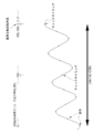
ワークWが回転した状態で、主軸台110A(主軸110)又は切削工具台130A(切削工具130)が、往復振動しながら移動し、切削工具130によって、ワークWを所定の形状に外形切削加工する場合、ワークWの周面は、図4に示すように、正弦曲線状に切削される。
なお正弦曲線状の波形の谷を通過する仮想線(1点鎖線)において、主軸位相0度から360度まで変化したときの位置の変化量が、前記送り量を示す。
図4に示されるように、ワークWの1回転当たりの主軸台110A(主軸110)又は切削工具台130Aの振動数Nが、3.5回(振動数N=3.5)を例に説明する。
なお正弦曲線状の波形の谷を通過する仮想線(1点鎖線)において、主軸位相0度から360度まで変化したときの位置の変化量が、前記送り量を示す。
図4に示されるように、ワークWの1回転当たりの主軸台110A(主軸110)又は切削工具台130Aの振動数Nが、3.5回(振動数N=3.5)を例に説明する。
この場合、n+1回転目(nは1以上の整数)の切削工具130により旋削されるワーク周面形状の位相の谷の最低点(切削工具130によって送り方向に最も切削された点となる点線波形グラフの山の頂点)の位置が、n回転目の切削工具130により旋削された形状の位相の谷の最低点(実線波形グラフの山の頂点)の位置に対して、主軸位相方向(グラフの横軸方向)でずれる。
これにより、切削工具130の往動時の切削加工部分と、復動時の切削加工部分とが一部重複し、ワーク周面のn+1回転目の切削部分に、n回転目に切削済みの部分が含まれ、振動切削中に切削工具130がワークWを切削しない所謂、空振り動作が生じる。
切削加工時にワークWから生じる切屑は、前記空振り動作によって順次分断される。
工作機械100は、切削工具130の切削送り方向に沿った前記往復振動によって切屑を分断しながら、ワークWの外形切削加工を円滑に行うことができる。
切削加工時にワークWから生じる切屑は、前記空振り動作によって順次分断される。
工作機械100は、切削工具130の切削送り方向に沿った前記往復振動によって切屑を分断しながら、ワークWの外形切削加工を円滑に行うことができる。
切削工具130の前記往復振動によって切屑を順次分断する場合、ワーク周面のn+1回転目の切削部分に、n回転目に切削済みの部分が含まれていればよい。
言い換えると、ワーク周面のn+1回転目(nは1以上の整数)における復動時の切削工具130の軌跡が、ワーク周面のn回転目における切削工具130の軌跡まで到達すればよい。
図4に示されるように、n+1回転目とn回転目のワークWにおける切削工具130により旋削される形状の位相が一致(同位相)とならなければよく、必ずしも180°反転させる必要はない。
言い換えると、ワーク周面のn+1回転目(nは1以上の整数)における復動時の切削工具130の軌跡が、ワーク周面のn回転目における切削工具130の軌跡まで到達すればよい。
図4に示されるように、n+1回転目とn回転目のワークWにおける切削工具130により旋削される形状の位相が一致(同位相)とならなければよく、必ずしも180°反転させる必要はない。
例えば振動数Nは、1.1や1.25、2.6、3.75等とすることができる。
ワークWの1回転で1回より少ない振動(0<振動数N<1.0)を行うように設定することもできる。
この場合、1振動に対して1回転以上主軸110が回転する。
ワークWの1回転で1回より少ない振動(0<振動数N<1.0)を行うように設定することもできる。
この場合、1振動に対して1回転以上主軸110が回転する。
工作機械100において、制御部C1による指令は、所定の指令時間単位毎で行われる。
主軸台110A(主軸110)又は切削工具台130A(切削工具130)の往復振動は、前記指令時間単位に基づく所定の周波数で動作が可能となる。
例えば、制御部C1によって1秒間に250回の指令を送ることが可能な工作機械100の場合、制御部C1による指令は、1÷250=4(ms)周期(指令時間単位毎)で行われる。
主軸台110A(主軸110)又は切削工具台130A(切削工具130)の往復振動は、前記指令時間単位に基づく所定の周波数で動作が可能となる。
例えば、制御部C1によって1秒間に250回の指令を送ることが可能な工作機械100の場合、制御部C1による指令は、1÷250=4(ms)周期(指令時間単位毎)で行われる。
本実施例の工作機械100は、振動手段の往復振動の位置に基づく所定のチェックタイミングで主軸110の位相である回転角度を検出する位置検出手段としての主軸回転角度エンコーダ(図示せず)を備えている。
また、制御部C1は、主軸110の回転と振動手段の往復振動とを予め定められた値となるように補正する補正手段を備えている。
制御部C1は、位置検出手段の検出位置情報と主軸110の回転数から得られる主軸110の回転角度の理論上の予測位置情報とを比べて、検出位置情報と予測位置情報との位置差があるとき、主軸110の回転数および振動手段の往復振動の一方を調整して前記位置差を小さくするように構成されている。
また、制御部C1は、主軸110の回転と振動手段の往復振動とを予め定められた値となるように補正する補正手段を備えている。
制御部C1は、位置検出手段の検出位置情報と主軸110の回転数から得られる主軸110の回転角度の理論上の予測位置情報とを比べて、検出位置情報と予測位置情報との位置差があるとき、主軸110の回転数および振動手段の往復振動の一方を調整して前記位置差を小さくするように構成されている。
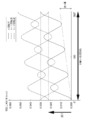
例えば、図5に示すように、主軸1回転当たりの切削工具130の振動数が3.5回とし、チェックタイミングが3.5振動ごとであるとし、14回の指令で切削工具130が3.5振動する場合について図6~図9に沿って説明する。
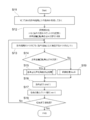
図6のステップS11では、制御部C1が、上述したような指令時間単位周期ごとの指令を、例えば14指令サイクルとなるように、生成する。
図6のステップS11では、制御部C1が、上述したような指令時間単位周期ごとの指令を、例えば14指令サイクルとなるように、生成する。
ステップS12では、制御部C1が、変数iを初期化する。
ステップS13では、指令ごとに発生するトリガを待ち、トリガがあればステップS14へ進む。
ステップS14では、制御部C1が、基準主軸回転角度が未決定か否かを判定し、未決定であると判定した場合はステップS15へ進み、未決定ではないと判定した場合はステップS19へ進む。
なお、例えば、最初に基準主軸回転角度が決定されていた場合であっても、最初に基準主軸回転角度を次のチェックタイミングのときにずれ量を含めた新たな基準主軸回転角度に置き換えてもよい。
ステップS13では、指令ごとに発生するトリガを待ち、トリガがあればステップS14へ進む。
ステップS14では、制御部C1が、基準主軸回転角度が未決定か否かを判定し、未決定であると判定した場合はステップS15へ進み、未決定ではないと判定した場合はステップS19へ進む。
なお、例えば、最初に基準主軸回転角度が決定されていた場合であっても、最初に基準主軸回転角度を次のチェックタイミングのときにずれ量を含めた新たな基準主軸回転角度に置き換えてもよい。
ステップS15では、詳しくは後述する基準主軸回転角度決定処理を行う。
ステップS16では、制御部C1が指令を出力する。
ステップS17では、指令の数のカウント、すなわち、変数iをステップS17を通過するたびに1つ増加させる。
ステップS18では、切削工具130が切削終了点に到達したか否かを制御部C1が判定し、到達したと判定した場合はシーケンスを終了し、到達していないと判定した場合はステップS13へ戻る。
ステップS19では、詳しくは後述する同期処理A、または同期処理Bを実行し、ステップS16へ進む。
ステップS16では、制御部C1が指令を出力する。
ステップS17では、指令の数のカウント、すなわち、変数iをステップS17を通過するたびに1つ増加させる。
ステップS18では、切削工具130が切削終了点に到達したか否かを制御部C1が判定し、到達したと判定した場合はシーケンスを終了し、到達していないと判定した場合はステップS13へ戻る。
ステップS19では、詳しくは後述する同期処理A、または同期処理Bを実行し、ステップS16へ進む。
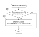
図7のステップS21では、制御部C1が所定のチェックタイミングか否かを判定し、チェックタイミングであると判定した場合はステップS22へ進み、チェックタイミングではないと判定した場合は基準主軸回転角度決定処理のシーケンスを終了して図6のステップS16へ進む。
ステップS22では、制御部C1が、現在の主軸回転角度エンコーダの出力値を記憶し、この出力値を基準主軸回転角度とする。
本発明の理解を容易にするために、例えば0°(360°)を基準主軸回転角度とする。
そして、基準主軸回転角度決定処理のシーケンスを終了して図6のステップS16へ進む。
ステップS22では、制御部C1が、現在の主軸回転角度エンコーダの出力値を記憶し、この出力値を基準主軸回転角度とする。
本発明の理解を容易にするために、例えば0°(360°)を基準主軸回転角度とする。
そして、基準主軸回転角度決定処理のシーケンスを終了して図6のステップS16へ進む。
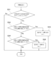
図8のステップS31では、制御部C1が所定のチェックタイミングか否かを判定し、チェックタイミングであると判定した場合はステップS32へ進み、チェックタイミングではないと判定した場合は同期処理Aのシーケンスを終了して図6のステップS16へ進む。
ステップS32では、制御部C1が、現在の主軸回転角度エンコーダの出力値と基準主軸回転角度とを比べて、基準主軸回転角度に対して振動手段の往復振動が進んでいるか否かを判定する。
例えば、現在の主軸回転角度エンコーダの出力値が180°以上360°未満(基準主軸回転角度とした0°よりも遅れている方向の角度)である場合は振動手段の往復振動が進んでいると判定してステップS33へ進み、それ以外である場合は振動手段の往復振動が進んでいないと判定してステップS34へ進む。
ステップS33では、順番が1つ前の指令を制御部C1が再び選択して1回前の同じ指令を送ることで指令のタイミングの1つ分を遅らせて主軸110の回転と振動手段の往復振動とを予め定められた値となるように補正して変数iの値を1つ減らし、同期処理Aのシーケンスを終了して図6のステップS16へ進む。
例えば、現在の主軸回転角度エンコーダの出力値が180°以上360°未満(基準主軸回転角度とした0°よりも遅れている方向の角度)である場合は振動手段の往復振動が進んでいると判定してステップS33へ進み、それ以外である場合は振動手段の往復振動が進んでいないと判定してステップS34へ進む。
ステップS33では、順番が1つ前の指令を制御部C1が再び選択して1回前の同じ指令を送ることで指令のタイミングの1つ分を遅らせて主軸110の回転と振動手段の往復振動とを予め定められた値となるように補正して変数iの値を1つ減らし、同期処理Aのシーケンスを終了して図6のステップS16へ進む。
ステップS34では、制御部C1が、現在の主軸回転角度エンコーダの出力値と基準主軸回転角度とを比べて、基準主軸回転角度に対して振動手段の往復振動が遅れているか否かを判定する。
例えば、現在の主軸回転角度エンコーダの出力値が0°より大きく180°未満である場合は振動手段の往復振動が遅れていると判定してステップS35へ進み、それ以外である場合は振動手段の往復振動が遅れていないと判定し、同期処理Aのシーケンスを終了して図6のステップS16へ進む。
例えば、現在の主軸回転角度エンコーダの出力値が0°より大きく180°未満である場合は振動手段の往復振動が遅れていると判定してステップS35へ進み、それ以外である場合は振動手段の往復振動が遅れていないと判定し、同期処理Aのシーケンスを終了して図6のステップS16へ進む。
ステップS35では、順番が1つ後の指令を制御部C1が選択して1つ指令を飛ばして、すなわちスキップしてその次の指令を送ることで指令のタイミングの1つ分を早めて主軸110の回転と振動手段の往復振動とを予め定められた値となるように補正して変数iの値を1つ増やし、同期処理Aのシーケンスを終了して図6のステップS16へ進む。
以上、説明したように、同期処理Aでは、補正手段としての制御部C1が、振動手段の指令が可能な周期単位で振動手段による振動タイミングを早めるまたは遅らせて主軸110の回転と振動手段の往復振動とを予め定められた値となるように補正をするように構成されている。
すなわち、制御部C1が、振動手段の指令が可能な周期単位で振動手段による振動タイミングを早めるまたは遅らせて主軸110の回転と振動手段の往復振動との同期をとるように構成されている。
なお、現在の主軸回転角度エンコーダの出力値と基準主軸回転角度との差の大きさに応じて、ステップS33、S35における変数iの値の増減量を2以上にしてもよい。
以上、説明したように、同期処理Aでは、補正手段としての制御部C1が、振動手段の指令が可能な周期単位で振動手段による振動タイミングを早めるまたは遅らせて主軸110の回転と振動手段の往復振動とを予め定められた値となるように補正をするように構成されている。
すなわち、制御部C1が、振動手段の指令が可能な周期単位で振動手段による振動タイミングを早めるまたは遅らせて主軸110の回転と振動手段の往復振動との同期をとるように構成されている。
なお、現在の主軸回転角度エンコーダの出力値と基準主軸回転角度との差の大きさに応じて、ステップS33、S35における変数iの値の増減量を2以上にしてもよい。
図9のステップS41では、制御部C1が所定のチェックタイミングか否かを判定し、チェックタイミングであると判定した場合はステップS42へ進み、チェックタイミングではないと判定した場合は同期処理Bのシーケンスを終了して図6のステップS16へ進む。
ステップS42では、上述した同期処理AのステップS32と同様、制御部C1が、現在の主軸回転角度エンコーダの出力値と基準主軸回転角度とを比べて、基準主軸回転角度に対して振動手段の往復振動が進んでいるか否かを判定する。
ステップS42では、上述した同期処理AのステップS32と同様、制御部C1が、現在の主軸回転角度エンコーダの出力値と基準主軸回転角度とを比べて、基準主軸回転角度に対して振動手段の往復振動が進んでいるか否かを判定する。
ステップS43では、主軸110の回転速度を上げて主軸110の回転と振動手段の往復振動とを予め定められた値となるように補正をするように制御部C1が主軸110の回転数の設定値Sを例えば1回転分増加させ、同期処理Bのシーケンスを終了して図6のステップS16へ進む。
ステップS44では、上述した同期処理AのステップS34と同様、制御部C1が、現在の主軸回転角度エンコーダの出力値と基準主軸回転角度とを比べて、基準主軸回転角度に対して振動手段の往復振動が遅れているか否かを判定する。
ステップS44では、上述した同期処理AのステップS34と同様、制御部C1が、現在の主軸回転角度エンコーダの出力値と基準主軸回転角度とを比べて、基準主軸回転角度に対して振動手段の往復振動が遅れているか否かを判定する。
ステップS45では、主軸110の回転速度を下げて主軸110の回転と振動手段の往復振動とを予め定められた値となるように補正するように制御部C1が主軸110の回転数の設定値Sを例えば1回転分減少させ、同期処理Bのシーケンスを終了して図6のステップS16へ進む。
以上、説明したように、同期処理Bでは、補正手段としての制御部C1が、主軸110の回転数を大きくまたは小さくして主軸110の回転と振動手段の往復振動とを予め定められた値となるように補正するように構成されている。
すなわち、制御部C1が、主軸110の回転数を大きくまたは小さくして主軸110の回転と振動手段の往復振動との同期をとるように構成されている。
以上、説明したように、同期処理Bでは、補正手段としての制御部C1が、主軸110の回転数を大きくまたは小さくして主軸110の回転と振動手段の往復振動とを予め定められた値となるように補正するように構成されている。
すなわち、制御部C1が、主軸110の回転数を大きくまたは小さくして主軸110の回転と振動手段の往復振動との同期をとるように構成されている。
なお、現在の主軸回転角度エンコーダの出力値と基準主軸回転角度との差の大きさに応じて、ステップS43、S45における主軸110の回転数の設定値Sの増減量を2回転以上にしてもよい。
また、本実施例では、位置検出手段が、振動手段の往復振動の位置に基づく所定のチェックタイミングで主軸110の回転角度を検出するように構成したが、主軸110の回転角度に基づく所定のタイミングで振動手段の往復振動の位置を検出するように構成してもよい。
あるいは、所定のタイミングが、相対回転の1回転の内に複数設定される構成としても良い。
例えば、図10に示すように、主軸1回転当たり14回の指令で切削工具130の振動数を3.5回とし、180°の基準主軸回転角度ごとにチェックタイミングを設けた場合、チェックタイミングが、主軸1回転当たり2回となる。
そして、補正手段としての制御部C1が、位置検出手段の検出位置情報と主軸110の回転数から得られる主軸110の回転角度の予測位置情報とを比べて、検出位置情報と予測位置情報との位置差があるとき、この位置差を小さくするように主軸110の回転数および振動手段の往復振動の一方を調整して主軸110の回転と振動手段の往復振動との同期をとるように構成してもよい。
また、本実施例では、位置検出手段が、振動手段の往復振動の位置に基づく所定のチェックタイミングで主軸110の回転角度を検出するように構成したが、主軸110の回転角度に基づく所定のタイミングで振動手段の往復振動の位置を検出するように構成してもよい。
あるいは、所定のタイミングが、相対回転の1回転の内に複数設定される構成としても良い。
例えば、図10に示すように、主軸1回転当たり14回の指令で切削工具130の振動数を3.5回とし、180°の基準主軸回転角度ごとにチェックタイミングを設けた場合、チェックタイミングが、主軸1回転当たり2回となる。
そして、補正手段としての制御部C1が、位置検出手段の検出位置情報と主軸110の回転数から得られる主軸110の回転角度の予測位置情報とを比べて、検出位置情報と予測位置情報との位置差があるとき、この位置差を小さくするように主軸110の回転数および振動手段の往復振動の一方を調整して主軸110の回転と振動手段の往復振動との同期をとるように構成してもよい。
なお、本実施例では、上述した図4のように、制御部C1がワークWのn+1回転目(nは1以上の整数)における復動時の切削工具130の軌跡を、ワークWのn回転目における切削工具130の軌跡と交差させるように制御したが、交差させずに到達させるだけでもよい。
言い換えると、往動時の切削加工部分と復動時の切削加工部分とが重複するように制御したが、往動時の切削加工部分と復動時の切削加工部分とが接するように制御してもよい。
これによって、1振動において切削工具130の往動時の切削加工部分に、復動時の切削加工部分が理論上「点」として含まれ、復動中に切削工具130がワークWを切削しない所謂、空振り動作が「点」で生じることにより、切削加工時にワークWから生じる切屑は、前記空振り動作(往動時の切削加工部分と、復動時の切削加工部分とが接する点)によって順次分断される。
言い換えると、往動時の切削加工部分と復動時の切削加工部分とが重複するように制御したが、往動時の切削加工部分と復動時の切削加工部分とが接するように制御してもよい。
これによって、1振動において切削工具130の往動時の切削加工部分に、復動時の切削加工部分が理論上「点」として含まれ、復動中に切削工具130がワークWを切削しない所謂、空振り動作が「点」で生じることにより、切削加工時にワークWから生じる切屑は、前記空振り動作(往動時の切削加工部分と、復動時の切削加工部分とが接する点)によって順次分断される。
100 ・・・ 工作機械
110 ・・・ 主軸
110A・・・ 主軸台
120 ・・・ チャック
130 ・・・ 切削工具
130A・・・ 切削工具台
150 ・・・ X軸方向送り機構
151 ・・・ ベース
152 ・・・ X軸方向ガイドレール
153 ・・・ X軸方向送りテーブル
154 ・・・ X軸方向ガイド
155 ・・・ リニアサーボモータ
155a・・・ 可動子
155b・・・ 固定子
160 ・・・ Z軸方向送り機構
161 ・・・ ベース
162 ・・・ Z軸方向ガイドレール
163 ・・・ Z軸方向送りテーブル
164 ・・・ Z軸方向ガイド
165 ・・・ リニアサーボモータ
165a・・・ 可動子
165b・・・ 固定子
C ・・・ 制御装置
C1 ・・・ 制御部
W ・・・ ワーク
110 ・・・ 主軸
110A・・・ 主軸台
120 ・・・ チャック
130 ・・・ 切削工具
130A・・・ 切削工具台
150 ・・・ X軸方向送り機構
151 ・・・ ベース
152 ・・・ X軸方向ガイドレール
153 ・・・ X軸方向送りテーブル
154 ・・・ X軸方向ガイド
155 ・・・ リニアサーボモータ
155a・・・ 可動子
155b・・・ 固定子
160 ・・・ Z軸方向送り機構
161 ・・・ ベース
162 ・・・ Z軸方向ガイドレール
163 ・・・ Z軸方向送りテーブル
164 ・・・ Z軸方向ガイド
165 ・・・ リニアサーボモータ
165a・・・ 可動子
165b・・・ 固定子
C ・・・ 制御装置
C1 ・・・ 制御部
W ・・・ ワーク
Claims (6)
- ワークを保持するワーク保持手段と、前記ワークを切削加工する切削工具を保持する刃物台と、前記ワーク保持手段と刃物台との相対移動によってワークに対して切削工具を所定の加工送り方向に送り動作させる送り手段と、前記ワーク保持手段と刃物台とを相対的に振動させる振動手段と、前記ワークと切削工具とを相対的に回転させる回転手段とを備え、
前記ワークと前記切削工具との相対回転と、前記ワークに対する前記切削工具の前記加工送り方向への前記往復振動を伴う送り動作とによって、ワークの加工を実行させる工作機械であって、
前記相対回転の回転角度又は前記ワーク保持手段あるいは刃物台を所定の座標位置に移動させる指令に基づく所定のタイミングを用いて、前記相対回転の回転角度又は前記ワーク保持手段あるいは刃物台の座標位置を検出する位置検出手段と、
該位置検出手段によって検出された回転角度の値又は座標位置の値を予め定められた値となるように、前記相対回転の回転数又は指令を補正する補正手段とを備えて前記送り動作を実行する工作機械。 - 前記位置検出手段が、前記相対回転の1回転中に回転角度の値又は座標位置の値を複数回検出する請求項1に記載の工作機械。
- 前記位置検出手段が、前記ワーク保持手段を備えた主軸の回転角度を検出する主軸回転角度エンコーダである請求項1または請求項2に記載の工作機械。
- 前記補正手段が、前記振動手段の指令が可能な周期単位で前記振動手段による振動タイミングを早めるまたは遅らせる請求項1乃至請求項3に記載の工作機械。
- 前記補正手段が、前記相対回転の回転数を大きくまたは小さくする請求項1乃至請求項3に記載の工作機械。
- ワークを保持するワーク保持手段と、前記ワークを切削加工する切削工具を保持する刃物台と、前記ワーク保持手段と刃物台との相対移動によってワークに対して切削工具を所定の加工送り方向に送り動作させる送り手段と、前記ワーク保持手段と刃物台とを相対的に振動させる振動手段と、前記ワークと切削工具とを相対的に回転させる回転手段とを備えた工作機械に設けられ、
前記ワークと前記切削工具との相対回転と、前記ワークに対する前記切削工具の加工送り方向への前記往復振動を伴う送り動作とによって、前記工作機械にワークの加工を実行させる工作機械の制御装置であって、
前記相対回転の回転角度又は前記ワーク保持手段あるいは刃物台を所定の座標位置に移動させる指令に基づく所定のタイミングを用いて、前記相対回転の回転角度又は前記ワーク保持手段あるいは刃物台の座標位置を検出する位置検出手段を備え、該位置検出手段によって検出された回転角度の値又は座標位置の値を予め定められた値となるように、前記相対回転の回転数又は指令を補正する補正手段を備えて前記送り動作を実行する工作機械の制御装置。
Priority Applications (1)
| Application Number | Priority Date | Filing Date | Title |
|---|---|---|---|
| JP2017506551A JP6608426B2 (ja) | 2015-03-18 | 2016-03-15 | 工作機械及びこの工作機械の制御装置 |
Applications Claiming Priority (2)
| Application Number | Priority Date | Filing Date | Title |
|---|---|---|---|
| JP2015-055234 | 2015-03-18 | ||
| JP2015055234 | 2015-03-18 |
Publications (1)
| Publication Number | Publication Date |
|---|---|
| WO2016148116A1 true WO2016148116A1 (ja) | 2016-09-22 |
Family
ID=56918829
Family Applications (1)
| Application Number | Title | Priority Date | Filing Date |
|---|---|---|---|
| PCT/JP2016/058055 Ceased WO2016148116A1 (ja) | 2015-03-18 | 2016-03-15 | 工作機械及びこの工作機械の制御装置 |
Country Status (3)
| Country | Link |
|---|---|
| JP (1) | JP6608426B2 (ja) |
| TW (1) | TW201634176A (ja) |
| WO (1) | WO2016148116A1 (ja) |
Cited By (8)
| Publication number | Priority date | Publication date | Assignee | Title |
|---|---|---|---|---|
| JP2018094690A (ja) * | 2016-12-15 | 2018-06-21 | シチズン時計株式会社 | 工作機械の制御装置および工作機械 |
| JP2018181100A (ja) * | 2017-04-18 | 2018-11-15 | ファナック株式会社 | 揺動切削を行う工作機械の制御装置 |
| CN108873804A (zh) * | 2017-05-16 | 2018-11-23 | 发那科株式会社 | 用于摆动切削的显示装置以及加工系统 |
| JP2019008665A (ja) * | 2017-06-27 | 2019-01-17 | ファナック株式会社 | 制御装置 |
| JP2019040252A (ja) * | 2017-08-22 | 2019-03-14 | ファナック株式会社 | 数値制御装置 |
| CN112368093A (zh) * | 2018-09-07 | 2021-02-12 | 山崎马扎克公司 | 机床、利用机床的加工方法以及用于机床的加工程序 |
| CN115516390A (zh) * | 2020-05-14 | 2022-12-23 | 发那科株式会社 | 机床的控制装置、控制系统 |
| TWI789382B (zh) * | 2017-03-29 | 2023-01-11 | 日商西鐵城時計股份有限公司 | 工具機的控制裝置以及工具機 |
Families Citing this family (3)
| Publication number | Priority date | Publication date | Assignee | Title |
|---|---|---|---|---|
| JP7053526B2 (ja) | 2019-03-25 | 2022-04-12 | ファナック株式会社 | 主軸振動測定システム、主軸振動測定方法、およびプログラム |
| WO2020209134A1 (ja) * | 2019-04-11 | 2020-10-15 | シチズン時計株式会社 | 工作機械及び検知方法 |
| JP7593791B2 (ja) * | 2019-12-16 | 2024-12-03 | ファナック株式会社 | 工作機械の制御装置及び工作機械制御方法 |
Citations (2)
| Publication number | Priority date | Publication date | Assignee | Title |
|---|---|---|---|---|
| JPH04323705A (ja) * | 1991-04-24 | 1992-11-12 | Fanuc Ltd | 回転軸同期繰り返し制御方法及び装置 |
| JP5033929B1 (ja) * | 2011-11-10 | 2012-09-26 | ハリキ精工株式会社 | 工作機械 |
Family Cites Families (2)
| Publication number | Priority date | Publication date | Assignee | Title |
|---|---|---|---|---|
| JP2009190119A (ja) * | 2008-02-14 | 2009-08-27 | Excel Engineering:Kk | 切りくず分断機能を備えた切削加工装置および切削加工方法 |
| CN104995571B (zh) * | 2013-02-12 | 2017-03-08 | 三菱电机株式会社 | 数控装置 |
-
2016
- 2016-03-15 WO PCT/JP2016/058055 patent/WO2016148116A1/ja not_active Ceased
- 2016-03-15 TW TW105107934A patent/TW201634176A/zh unknown
- 2016-03-15 JP JP2017506551A patent/JP6608426B2/ja not_active Expired - Fee Related
Patent Citations (2)
| Publication number | Priority date | Publication date | Assignee | Title |
|---|---|---|---|---|
| JPH04323705A (ja) * | 1991-04-24 | 1992-11-12 | Fanuc Ltd | 回転軸同期繰り返し制御方法及び装置 |
| JP5033929B1 (ja) * | 2011-11-10 | 2012-09-26 | ハリキ精工株式会社 | 工作機械 |
Cited By (16)
| Publication number | Priority date | Publication date | Assignee | Title |
|---|---|---|---|---|
| JP2018094690A (ja) * | 2016-12-15 | 2018-06-21 | シチズン時計株式会社 | 工作機械の制御装置および工作機械 |
| TWI789382B (zh) * | 2017-03-29 | 2023-01-11 | 日商西鐵城時計股份有限公司 | 工具機的控制裝置以及工具機 |
| US10514673B2 (en) | 2017-04-18 | 2019-12-24 | Fanuc Corporation | Control device for machine tool performing oscillation cutting |
| JP2018181100A (ja) * | 2017-04-18 | 2018-11-15 | ファナック株式会社 | 揺動切削を行う工作機械の制御装置 |
| CN108873804B (zh) * | 2017-05-16 | 2020-07-07 | 发那科株式会社 | 用于摆动切削的显示装置以及加工系统 |
| US10503141B2 (en) | 2017-05-16 | 2019-12-10 | Fanuc Corporation | Display device and machining system for oscillation cutting |
| CN108873804A (zh) * | 2017-05-16 | 2018-11-23 | 发那科株式会社 | 用于摆动切削的显示装置以及加工系统 |
| JP2018195002A (ja) * | 2017-05-16 | 2018-12-06 | ファナック株式会社 | 揺動切削のための表示装置および加工システム |
| US10466682B2 (en) | 2017-06-27 | 2019-11-05 | Fanuc Corporation | Controller |
| JP2019008665A (ja) * | 2017-06-27 | 2019-01-17 | ファナック株式会社 | 制御装置 |
| JP2019040252A (ja) * | 2017-08-22 | 2019-03-14 | ファナック株式会社 | 数値制御装置 |
| CN112368093A (zh) * | 2018-09-07 | 2021-02-12 | 山崎马扎克公司 | 机床、利用机床的加工方法以及用于机床的加工程序 |
| CN112368093B (zh) * | 2018-09-07 | 2024-02-20 | 山崎马扎克公司 | 机床、利用机床的加工方法以及用于机床的存储介质 |
| US11998990B2 (en) | 2018-09-07 | 2024-06-04 | Yamazaki Mazak Corporation | Machine tool, machining method using a machine tool, and machining program for machine tool |
| CN115516390A (zh) * | 2020-05-14 | 2022-12-23 | 发那科株式会社 | 机床的控制装置、控制系统 |
| US12440936B2 (en) | 2020-05-14 | 2025-10-14 | Fanuc Corporation | Control device and control system for machine tool |
Also Published As
| Publication number | Publication date |
|---|---|
| TW201634176A (zh) | 2016-10-01 |
| JP6608426B2 (ja) | 2019-11-20 |
| JPWO2016148116A1 (ja) | 2018-01-11 |
Similar Documents
| Publication | Publication Date | Title |
|---|---|---|
| JP6608426B2 (ja) | 工作機械及びこの工作機械の制御装置 | |
| JP7304315B2 (ja) | 工作機械及びこの工作機械の制御装置 | |
| JP6343676B2 (ja) | 工作機械及びこの工作機械の制御装置 | |
| JP6416217B2 (ja) | 工作機械の制御装置及びこの制御装置を備えた工作機械 | |
| JP6914840B2 (ja) | 工作機械の制御装置及びこの制御装置を備えた工作機械 | |
| US11338404B2 (en) | Machine tool and control apparatus of the machine tool | |
| JP6470085B2 (ja) | 工作機械及びこの工作機械の制御装置 | |
| CN110475637B (zh) | 机床的控制装置以及机床 | |
| JP7214568B2 (ja) | 工作機械及びこの工作機械の制御装置 | |
| WO2015146946A1 (ja) | 工作機械の制御装置及びこの制御装置を備えた工作機械 | |
| JP6289766B2 (ja) | 工作機械の制御装置、工作機械 | |
| WO2016152768A1 (ja) | 工作機械及びこの工作機械の制御装置 | |
| WO2019073908A1 (ja) | 工作機械 | |
| JP2016182652A (ja) | 工作機械及びこの工作機械の制御装置 |
Legal Events
| Date | Code | Title | Description |
|---|---|---|---|
| 121 | Ep: the epo has been informed by wipo that ep was designated in this application |
Ref document number: 16764946 Country of ref document: EP Kind code of ref document: A1 |
|
| ENP | Entry into the national phase |
Ref document number: 2017506551 Country of ref document: JP Kind code of ref document: A |
|
| NENP | Non-entry into the national phase |
Ref country code: DE |
|
| 122 | Ep: pct application non-entry in european phase |
Ref document number: 16764946 Country of ref document: EP Kind code of ref document: A1 |