WO2016148023A1 - 車両用通信システム及び車載通信装置 - Google Patents
車両用通信システム及び車載通信装置 Download PDFInfo
- Publication number
- WO2016148023A1 WO2016148023A1 PCT/JP2016/057610 JP2016057610W WO2016148023A1 WO 2016148023 A1 WO2016148023 A1 WO 2016148023A1 JP 2016057610 W JP2016057610 W JP 2016057610W WO 2016148023 A1 WO2016148023 A1 WO 2016148023A1
- Authority
- WO
- WIPO (PCT)
- Prior art keywords
- vehicle
- signal
- wireless device
- unit
- transmission
- Prior art date
- Legal status (The legal status is an assumption and is not a legal conclusion. Google has not performed a legal analysis and makes no representation as to the accuracy of the status listed.)
- Ceased
Links
Images



Classifications
-
- B—PERFORMING OPERATIONS; TRANSPORTING
- B60—VEHICLES IN GENERAL
- B60C—VEHICLE TYRES; TYRE INFLATION; TYRE CHANGING; CONNECTING VALVES TO INFLATABLE ELASTIC BODIES IN GENERAL; DEVICES OR ARRANGEMENTS RELATED TO TYRES
- B60C23/00—Devices for measuring, signalling, controlling, or distributing tyre pressure or temperature, specially adapted for mounting on vehicles; Arrangement of tyre inflating devices on vehicles, e.g. of pumps or of tanks; Tyre cooling arrangements
- B60C23/02—Signalling devices actuated by tyre pressure
- B60C23/04—Signalling devices actuated by tyre pressure mounted on the wheel or tyre
- B60C23/0408—Signalling devices actuated by tyre pressure mounted on the wheel or tyre transmitting the signals by non-mechanical means from the wheel or tyre to a vehicle body mounted receiver
- B60C23/0483—Wireless routers between wheel mounted transmitters and chassis mounted receivers
-
- H—ELECTRICITY
- H04—ELECTRIC COMMUNICATION TECHNIQUE
- H04B—TRANSMISSION
- H04B1/00—Details of transmission systems, not covered by a single one of groups H04B3/00 - H04B13/00; Details of transmission systems not characterised by the medium used for transmission
- H04B1/38—Transceivers, i.e. devices in which transmitter and receiver form a structural unit and in which at least one part is used for functions of transmitting and receiving
- H04B1/3822—Transceivers, i.e. devices in which transmitter and receiver form a structural unit and in which at least one part is used for functions of transmitting and receiving specially adapted for use in vehicles
-
- B—PERFORMING OPERATIONS; TRANSPORTING
- B60—VEHICLES IN GENERAL
- B60C—VEHICLE TYRES; TYRE INFLATION; TYRE CHANGING; CONNECTING VALVES TO INFLATABLE ELASTIC BODIES IN GENERAL; DEVICES OR ARRANGEMENTS RELATED TO TYRES
- B60C23/00—Devices for measuring, signalling, controlling, or distributing tyre pressure or temperature, specially adapted for mounting on vehicles; Arrangement of tyre inflating devices on vehicles, e.g. of pumps or of tanks; Tyre cooling arrangements
- B60C23/02—Signalling devices actuated by tyre pressure
- B60C23/04—Signalling devices actuated by tyre pressure mounted on the wheel or tyre
- B60C23/0408—Signalling devices actuated by tyre pressure mounted on the wheel or tyre transmitting the signals by non-mechanical means from the wheel or tyre to a vehicle body mounted receiver
- B60C23/0422—Signalling devices actuated by tyre pressure mounted on the wheel or tyre transmitting the signals by non-mechanical means from the wheel or tyre to a vehicle body mounted receiver characterised by the type of signal transmission means
- B60C23/0433—Radio signals
- B60C23/0435—Vehicle body mounted circuits, e.g. transceiver or antenna fixed to central console, door, roof, mirror or fender
- B60C23/0438—Vehicle body mounted circuits, e.g. transceiver or antenna fixed to central console, door, roof, mirror or fender comprising signal transmission means, e.g. for a bidirectional communication with a corresponding wheel mounted receiver
- B60C23/0442—Vehicle body mounted circuits, e.g. transceiver or antenna fixed to central console, door, roof, mirror or fender comprising signal transmission means, e.g. for a bidirectional communication with a corresponding wheel mounted receiver the transmitted signal comprises further information, e.g. instruction codes, sensor characteristics or identification data
-
- B—PERFORMING OPERATIONS; TRANSPORTING
- B60—VEHICLES IN GENERAL
- B60C—VEHICLE TYRES; TYRE INFLATION; TYRE CHANGING; CONNECTING VALVES TO INFLATABLE ELASTIC BODIES IN GENERAL; DEVICES OR ARRANGEMENTS RELATED TO TYRES
- B60C23/00—Devices for measuring, signalling, controlling, or distributing tyre pressure or temperature, specially adapted for mounting on vehicles; Arrangement of tyre inflating devices on vehicles, e.g. of pumps or of tanks; Tyre cooling arrangements
- B60C23/02—Signalling devices actuated by tyre pressure
- B60C23/04—Signalling devices actuated by tyre pressure mounted on the wheel or tyre
- B60C23/0408—Signalling devices actuated by tyre pressure mounted on the wheel or tyre transmitting the signals by non-mechanical means from the wheel or tyre to a vehicle body mounted receiver
- B60C23/0422—Signalling devices actuated by tyre pressure mounted on the wheel or tyre transmitting the signals by non-mechanical means from the wheel or tyre to a vehicle body mounted receiver characterised by the type of signal transmission means
- B60C23/0433—Radio signals
- B60C23/0447—Wheel or tyre mounted circuits
- B60C23/0455—Transmission control of wireless signals
- B60C23/0461—Transmission control of wireless signals externally triggered, e.g. by wireless request signal, magnet or manual switch
-
- B—PERFORMING OPERATIONS; TRANSPORTING
- B60—VEHICLES IN GENERAL
- B60C—VEHICLE TYRES; TYRE INFLATION; TYRE CHANGING; CONNECTING VALVES TO INFLATABLE ELASTIC BODIES IN GENERAL; DEVICES OR ARRANGEMENTS RELATED TO TYRES
- B60C23/00—Devices for measuring, signalling, controlling, or distributing tyre pressure or temperature, specially adapted for mounting on vehicles; Arrangement of tyre inflating devices on vehicles, e.g. of pumps or of tanks; Tyre cooling arrangements
- B60C23/02—Signalling devices actuated by tyre pressure
- B60C23/04—Signalling devices actuated by tyre pressure mounted on the wheel or tyre
- B60C23/0408—Signalling devices actuated by tyre pressure mounted on the wheel or tyre transmitting the signals by non-mechanical means from the wheel or tyre to a vehicle body mounted receiver
- B60C23/0422—Signalling devices actuated by tyre pressure mounted on the wheel or tyre transmitting the signals by non-mechanical means from the wheel or tyre to a vehicle body mounted receiver characterised by the type of signal transmission means
- B60C23/0433—Radio signals
- B60C23/0447—Wheel or tyre mounted circuits
- B60C23/0455—Transmission control of wireless signals
- B60C23/0464—Transmission control of wireless signals to avoid signal interference
-
- B—PERFORMING OPERATIONS; TRANSPORTING
- B60—VEHICLES IN GENERAL
- B60R—VEHICLES, VEHICLE FITTINGS, OR VEHICLE PARTS, NOT OTHERWISE PROVIDED FOR
- B60R16/00—Electric or fluid circuits specially adapted for vehicles and not otherwise provided for; Arrangement of elements of electric or fluid circuits specially adapted for vehicles and not otherwise provided for
- B60R16/02—Electric or fluid circuits specially adapted for vehicles and not otherwise provided for; Arrangement of elements of electric or fluid circuits specially adapted for vehicles and not otherwise provided for electric constitutive elements
- B60R16/023—Electric or fluid circuits specially adapted for vehicles and not otherwise provided for; Arrangement of elements of electric or fluid circuits specially adapted for vehicles and not otherwise provided for electric constitutive elements for transmission of signals between vehicle parts or subsystems
-
- H—ELECTRICITY
- H04—ELECTRIC COMMUNICATION TECHNIQUE
- H04B—TRANSMISSION
- H04B15/00—Suppression or limitation of noise or interference
-
- H—ELECTRICITY
- H04—ELECTRIC COMMUNICATION TECHNIQUE
- H04B—TRANSMISSION
- H04B15/00—Suppression or limitation of noise or interference
- H04B15/02—Reducing interference from electric apparatus by means located at or near the interfering apparatus
- H04B15/04—Reducing interference from electric apparatus by means located at or near the interfering apparatus the interference being caused by substantially sinusoidal oscillations, e.g. in a receiver or in a tape-recorder
Definitions
- the present invention provides a vehicle communication system including a portable device and a vehicle-mounted wireless device that wirelessly transmit a signal using radio waves in the same frequency band, and a vehicle-mounted communication device that receives the signal, and the vehicle communication system
- the present invention relates to an in-vehicle communication device.
- TPMS Transire Pressure Monitoring System
- TPMS detects tire air pressure and wirelessly transmits a signal indicating the detected air pressure using radio waves in the UHF band, and is provided in the vehicle body, and receives a signal wirelessly transmitted from the in-vehicle wireless device
- An in-vehicle communication device that performs the notification, and a notification device that notifies the air pressure indicated by the received signal.
- the frequency band of the signal transmitted by the in-vehicle wireless device of TPMS is the same as the frequency band of the signal transmitted by the portable device constituting the passive entry system, the keyless entry system, the smart start system, etc., that is, the electronic key. May occur. Interference causes a malfunction of a passive entry system or the like. In addition, it may cause malfunction of the tire pressure monitoring system.
- An object of the present invention is to prevent interference between signals transmitted from an in-vehicle wireless device constituting one wireless communication system such as TPMS and a portable device constituting another wireless communication system.
- the object is to provide a vehicle communication system and an in-vehicle communication device.
- a vehicle communication system includes a portable device that wirelessly transmits a signal related to operation of a vehicle in a predetermined frequency band, an in-vehicle wireless device that wirelessly transmits a signal related to the vehicle in the predetermined frequency band, A vehicle communication system that is provided at a location different from the in-vehicle wireless device, and includes a vehicle-mounted communication device that performs wireless communication with the portable device and the in-vehicle wireless device, wherein the in-vehicle communication device includes: In-vehicle receiver that receives signals transmitted from the portable device and the in-vehicle wireless device, a determination unit that determines the presence or absence of interference based on the signal received by the in-vehicle receiver, and interference occurs in the determination unit An in-vehicle transmission unit that transmits a stop signal instructing stoppage of signal transmission to the portable device or the in-vehicle wireless device, the portable device or the in-vehicle wireless device outputs the stop signal. If received
- the present application can be realized not only as a vehicle communication system and an in-vehicle communication device including such a characteristic processing unit, but also as a vehicle communication method using such characteristic processing as a step.
- the program can be realized as a program for causing a computer to execute such steps. Moreover, it can implement
- FIG. 10 is a flowchart illustrating a processing procedure of the in-vehicle wireless device according to the fifth embodiment.
- 14 is a flowchart illustrating a processing procedure of the in-vehicle communication device according to the sixth embodiment.
- 14 is a flowchart illustrating a processing procedure of the in-vehicle communication device according to the sixth embodiment.
- FIG. 10 is a block diagram illustrating a configuration example of an in-vehicle wireless device according to a seventh embodiment.
- 15 is a flowchart illustrating a processing procedure of the in-vehicle wireless device according to the seventh embodiment. It is a block diagram which shows the example of 1 structure of the vehicle-mounted communication apparatus which concerns on Embodiment 8.
- FIG. 10 is a flowchart illustrating a processing procedure of the in-vehicle wireless device according to the fifth embodiment.
- 14 is a flowchart illustrating a processing procedure of the in-vehicle communication device according to the sixth embodiment.
- 14 is
- a vehicle communication system includes a portable device that wirelessly transmits a signal related to an operation of a vehicle in a predetermined frequency band, and an in-vehicle wireless that wirelessly transmits a signal related to the vehicle in the predetermined frequency band.
- the vehicle-mounted communication device that is provided at a location different from the vehicle-mounted wireless device and performs wireless communication between the portable device and the vehicle-mounted communication device, the vehicle-mounted communication device A vehicle-mounted receiving unit that receives signals transmitted from the portable device and the vehicle-mounted communication device, a determination unit that determines the presence or absence of interference based on the signal received by the vehicle-mounted receiving unit, and the determination unit
- the mobile device or the in-vehicle wireless device includes an in-vehicle transmission unit that transmits a stop signal that instructs the portable device or the in-vehicle wireless device to stop transmitting signals. Received stop signal If, it stops the transmission of the signal.
- the in-vehicle wireless device stops transmission of the signal for a predetermined time, and resumes transmission of the signal after the predetermined time has elapsed. Therefore, the in-vehicle communication device can receive a signal from the portable device during a predetermined time, and can receive a signal from the in-vehicle wireless device after the predetermined time has elapsed.
- the portable device may be configured to stop signal transmission for a predetermined time and resume signal transmission after a predetermined time has elapsed. Therefore, the in-vehicle communication device can receive a signal from the in-vehicle wireless device during a predetermined time, and can receive a signal from the portable device after the predetermined time has elapsed.
- the in-vehicle communication device when interference occurs, deletes the information of the signal received by the in-vehicle receiving unit at that time. Accordingly, it is possible to prevent erroneous information from being received due to interference.
- the in-vehicle transmission unit receives a signal transmitted from the portable device after transmitting a request signal for requesting signal transmission to the in-vehicle wireless device
- the in-vehicle transmission unit receives the signal transmitted from the portable device. It is preferable that the stop signal is transmitted to the in-vehicle wireless device before the signal is transmitted.
- requires transmission of a signal is transmitted to a vehicle-mounted radio
- the in-vehicle communication unit receives a signal transmitted from the portable device after transmitting the request signal, the in-vehicle communication device sends a stop signal to the in-vehicle wireless device before the signal is transmitted from the in-vehicle wireless device according to the request signal. Send.
- the in-vehicle communication device requests transmission of a signal to the in-vehicle wireless device, but when there is a possibility of interference due to the signal from the portable device, the in-vehicle wireless device immediately transmits a stop signal to the in-vehicle wireless device. Stop sending the signal. And the vehicle-mounted communication apparatus can receive the signal from a portable machine in the state which interference does not arise.
- an air pressure detection unit that detects an air pressure of a tire of the vehicle is provided, and the in-vehicle wireless device transmits a signal related to the air pressure detected by the air pressure detection unit.
- the in-vehicle wireless device transmits a signal related to the tire air pressure to the in-vehicle communication device.
- the in-vehicle communication device can prevent interference and obtain information related to tire air pressure.
- a vehicle speed detection unit that detects the speed of the vehicle is provided, and the vehicle-mounted transmission unit intermittently transmits a request signal that requests transmission of a signal to the vehicle-mounted radio, and the vehicle speed detection unit
- a configuration is preferable in which, when the detected speed is equal to or higher than a predetermined speed and the determination unit determines that interference has occurred, the transmission frequency of the request signal is increased.
- the in-vehicle transmission unit of the in-vehicle communication device intermittently transmits a request signal to the in-vehicle wireless device, and each time the in-vehicle wireless device receives the request signal, the signal related to the tire pressure is in-vehicle communication. Send to device.
- the in-vehicle transmission unit of the in-vehicle communication device increases the transmission frequency of the request signal when the speed of the vehicle is equal to or higher than a predetermined speed and interference occurs.
- the signal related to the tire air pressure is more important than the signal transmitted from the portable device. Therefore, when the vehicle speed is equal to or higher than the predetermined speed and interference occurs, the in-vehicle communication device increases the probability of successful reception of the important signal by causing the signal related to the tire air pressure to be transmitted more frequently. Can do.
- a vehicle speed detection unit that detects the speed of the vehicle is provided, and the in-vehicle transmission unit has a speed detected by the vehicle speed detection unit equal to or higher than a predetermined speed, and interference occurs in the determination unit.
- a predetermined instruction signal is transmitted to the in-vehicle wireless device, the in-vehicle wireless device intermittently transmits a signal related to the vehicle, and the in-vehicle receiving unit receives the instruction signal
- a configuration for increasing the transmission frequency of signals related to the vehicle is preferable.
- the in-vehicle wireless device intermittently transmits a signal related to the tire air pressure to the in-vehicle communication device.
- the in-vehicle transmission unit of the in-vehicle communication device transmits a predetermined instruction signal to the in-vehicle wireless device when the speed of the vehicle is equal to or higher than the predetermined speed and interference occurs.
- the in-vehicle wireless device increases the transmission frequency of a signal related to tire air pressure. Therefore, when the vehicle speed is equal to or higher than the predetermined speed and interference occurs, the in-vehicle communication device increases the probability of successful reception of the important signal by causing the signal related to the tire air pressure to be transmitted more frequently. Can do.
- the in-vehicle wireless device includes a monitoring unit that monitors the presence / absence of a signal in the predetermined frequency band transmitted from the outside, and transmits a signal related to the vehicle when there is no signal in the predetermined frequency band. It is preferable that the transmission of the signal related to the vehicle is stopped when there is a signal in the predetermined frequency band.
- the in-vehicle wireless device monitors a signal in a predetermined frequency band, and controls transmission and stop of the signal related to the vehicle according to the presence or absence of the signal in the frequency band. Therefore, the in-vehicle communication device can receive a signal transmitted from the in-vehicle wireless device in a situation where there is a low possibility of interference.
- An in-vehicle communication device includes a portable device that wirelessly transmits a signal related to an operation of a vehicle in a predetermined frequency band, and an in-vehicle wireless device that wirelessly transmits a signal related to the vehicle in the predetermined frequency band.
- a vehicle-mounted communication device that communicates with the vehicle-mounted receiving unit that receives the signal in the predetermined frequency band, and a determination unit that determines the presence or absence of interference based on the signal received by the vehicle-mounted receiving unit; And an in-vehicle transmission unit that transmits a stop signal that instructs the portable device or the in-vehicle wireless device to stop transmitting signals when it is determined by the determination unit that interference has occurred.
- the in-vehicle communication device can receive a signal transmitted from the portable device or the in-vehicle wireless device.
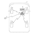
- FIG. 1 is a schematic diagram showing a configuration example of a vehicle communication system according to Embodiment 1 of the present invention.
- the vehicular communication system according to the first embodiment shares hardware related to radio communication and constitutes a radio communication system of a TPMS and a passive entry system.
- the vehicle communication system includes an in-vehicle communication device 1 provided at an appropriate location of a vehicle body, an in-vehicle wireless device 2 provided on each wheel of a tire 3 attached to the vehicle C, and a portable device 4 according to a passive entry system. And a notification device 5 according to TPMS.
- TPMS is composed of an in-vehicle communication device 1, an in-vehicle wireless device 2, and a notification device 5.
- the in-vehicle wireless device 2 periodically detects the air pressure of the tire 3 attached to each wheel, and transmits the detected air pressure to the in-vehicle communication device 1 by using a radio wave in a UHF (Ultra High Frequency) band.
- the in-vehicle communication device 1 acquires information on the air pressure of each tire 3 by performing wireless communication with each in-vehicle wireless device 2.
- a notification device 5 is connected to the in-vehicle communication device 1 via a communication line, and the in-vehicle communication device 1 transmits the acquired air pressure information to the notification device 5.
- the notification device 5 receives the air pressure information transmitted from the in-vehicle communication device 1 and notifies the air pressure.
- the notification device 5 issues a warning when the air pressure of the tire 3 is less than a predetermined threshold value.
- the passive entry system which comprises the communication system for vehicles is an example, and can apply this invention to the system which performs wireless communication between the portable device 4 and the vehicle-mounted communication apparatus 1, and performs various vehicle control.
- the communication system for a vehicle may constitute a smart start system that enables starting of a prime mover mounted on a vehicle without using a keyless entry system or a mechanical key together with TPMS.
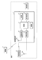
- FIG. 2 is a block diagram showing a configuration example of the in-vehicle communication device 1.
- the in-vehicle communication device 1 includes a control unit 11 that controls the operation of each component of the in-vehicle communication device 1.
- the control unit 11 is connected to a storage unit 12, an in-vehicle receiving unit 13, an in-vehicle transmitting unit 14, a time measuring unit 15, and an in-vehicle communication unit 16.
- the control unit 11 is a microcomputer having, for example, one or a plurality of CPUs (Central Processing Units), a multi-core CPU, a ROM (Read Only Memory), a RAM (Random Access Memory), an input / output interface, and the like.
- the CPU of the control unit 11 is connected to the storage unit 12, the in-vehicle receiving unit 13, the in-vehicle transmitting unit 14, the time measuring unit 15, and the in-vehicle communication unit 16 through an input / output interface.
- the control unit 11 executes the control program stored in the storage unit 12 to control the operation of each component unit, and the tire pressure monitoring process, the door locking and unlocking process, and the interference prevention process according to the present embodiment. Execute.
- the storage unit 12 is a nonvolatile memory such as an EEPROM (ElectricallyrErasable Programmable ROM) or a flash memory.
- the storage unit 12 executes the tire air pressure monitoring process, the door locking / unlocking process, and the interference prevention process according to the present embodiment by controlling the operation of each component of the in-vehicle communication device 1 by the control unit 11.
- the control program is stored.
- the in-vehicle receiving unit 13 is connected to an RF antenna 13a.
- the in-vehicle receiving unit 13 receives a signal transmitted from the in-vehicle wireless device 2 or the portable device 4 using radio waves in the RF band by the RF antenna 13a.
- the in-vehicle receiving unit 13 is a circuit that demodulates the received signal and outputs the demodulated signal to the control unit 11.
- a carrier wave a UHF (Ultra High Frequency) band of 300 MHz to 3 GHz is used, but the carrier wave is not limited to this frequency band.
- the in-vehicle transmission unit 14 is a circuit that modulates the signal output from the control unit 11 into an LF band signal and transmits the modulated signal from the LF antenna 14 a to the in-vehicle wireless device 2 or the portable device 4.
- the carrier wave uses an LF (Low Frequency) band of 30 kHz to 300 kHz, but is not limited to this frequency band.
- the timer unit 15 is constituted by, for example, a timer, a real-time clock, etc., starts timing according to the control of the control unit 11, and gives the timing result to the control unit 11.
- the in-vehicle communication unit 16 is a communication circuit that performs communication in accordance with a communication protocol such as CAN (Controller Area Network) or LIN (Local Interconnect Network), and transmits information related to the air pressure of the tire 3 to the notification device 5.
- a communication protocol such as CAN (Controller Area Network) or LIN (Local Interconnect Network)
- the notification device 5 is, for example, a display unit provided with a display unit or a speaker for notifying information related to the air pressure of the tire 3 transmitted from the in-vehicle communication unit 16 by an image or sound, or a display provided on an instrument panel instrument. Etc.
- the display unit is a liquid crystal display, an organic EL display, a head-up display, or the like.
- the notification device 5 displays the air pressure of each tire 3 provided in the vehicle C.
- the sensor control unit 21 is a microcomputer having, for example, one or a plurality of CPUs, a multi-core CPU, a ROM, a RAM, an input / output interface, and the like.
- the CPU of the sensor control unit 21 is connected to the sensor storage unit 22, the sensor transmission unit 23, the sensor reception unit 24, the air pressure detection unit 25, and the time measurement unit 26 via an input / output interface.
- the sensor control unit 21 reads a control program stored in the sensor storage unit 22 and controls each unit.
- the in-vehicle wireless device 2 includes a battery (not shown) and operates with electric power from the battery.
- the sensor storage unit 22 is a nonvolatile memory.
- the sensor storage unit 22 stores a control program for the CPU of the sensor control unit 21 to perform processing related to detection and transmission of the air pressure of the tire 3.
- the air pressure detection unit 25 includes, for example, a diaphragm, and detects the air pressure of the tire 3 based on the deformation amount of the diaphragm that changes depending on the magnitude of the pressure.
- the air pressure is an absolute pressure. Absolute pressure is the magnitude of pressure relative to absolute vacuum. In the present embodiment, it has been described that the air pressure detected by the air pressure detection unit 25 is an absolute pressure. However, a gauge pressure or a differential pressure indicating the magnitude of pressure with respect to a predetermined reference pressure may be detected. .
- the predetermined reference pressure is, for example, a median value, a lower limit value, an upper limit value, or the like of the range of air pressure when the tire 3 does not require inspection.
- the air pressure detection unit 25 outputs a signal indicating the detected air pressure of the tire 3 to the sensor control unit 21.
- the sensor control unit 21 generates a signal including information such as the air pressure of the tire 3 and the device ID unique to the in-vehicle wireless device 2 by executing the control program, and outputs the signal to the sensor transmission unit 23.
- the sensor transmission unit 23 is connected to an RF antenna 23a.
- the sensor transmission unit 23 modulates the signal generated by the sensor control unit 21 into a UHF band signal, and transmits the modulated signal using the RF antenna 23a.
- the sensor receiving unit 24 is connected to an LF antenna 24a.
- the sensor receiving unit 24 receives a signal transmitted from the in-vehicle communication device 1 using radio waves in the LF band by the LF antenna 24 a and outputs the received signal to the sensor control unit 21.
- FIG. 4 is a block diagram showing a configuration example of the portable device 4.
- the portable device 4 includes a portable device control unit 41 that controls the operation of each component of the portable device 4.
- a portable device storage unit 42, a portable transmission unit 43, a portable reception unit 44, and a signal strength measurement unit 45 are connected to the portable device control unit 41.
- the portable device control unit 41 is a microcomputer having, for example, one or a plurality of CPUs, a multi-core CPU, a ROM, a RAM, an input / output interface, and the like.
- the CPU of the portable device control unit 41 is connected to the portable device storage unit 42, the portable transmission unit 43, the portable reception unit 44, and the signal strength measurement unit 45 via an input / output interface.
- the portable device control unit 41 reads a control program stored in the portable device storage unit 42 and controls each unit.
- the portable device storage unit 42 is a nonvolatile memory.
- the portable device storage unit 42 controls the operation of each component of the portable device 4 by the portable device control unit 41 to transmit a signal including information for detecting the position of the portable device 4 to the in-vehicle communication device 1.
- a control program for executing processing to be transmitted is stored.
- the mobile receiver 44 is connected to the LF antenna 44a, receives various signals transmitted from the in-vehicle communication device 1 using radio waves in the LF band, and outputs the received signals to the mobile device controller 41.
- FIG. 8 is a flowchart showing a processing procedure of the in-vehicle communication device 1 according to the third embodiment.
- the control unit 11 of the in-vehicle communication device 1 according to the second embodiment executes the same processes as steps S11 to S14 of the first embodiment in steps S311 to S314.
- step S313: YES the control unit 11 according to the third embodiment transmits a stop signal instructing stop of signal transmission to the in-vehicle wireless device 2 by the in-vehicle transmission unit 14.
- Step S314 the information obtained by performing the reception process when interference occurs is discarded (Step S315), and the process returns to Step S313.
- the control unit 11 performs the same processing as steps S15 to S18 of the first embodiment in steps S316 to S319.
- the in-vehicle wireless device 2 transmits a signal related to the air pressure of the tire 3 in response to a request from the in-vehicle communication device 1, and the in-vehicle communication device 1. Receives the signal.
- the in-vehicle communication device 1 requests transmission of a signal to the in-vehicle wireless device 2, but there is a possibility that interference occurs due to the signal from the portable device 4, the in-vehicle wireless device 1 immediately transmits a stop signal to the in-vehicle wireless device 2. The transmission of the signal from the machine 2 is stopped.
- the vehicle-mounted communication apparatus 1 can receive the signal from the portable device 4 in a state where interference does not occur. Therefore, it is possible to prevent interference between signals transmitted from the in-vehicle wireless device 2 constituting the TPMS and the portable device 4 constituting the passive entry system.
- Embodiment 4 was demonstrated as a modification of Embodiment 1, you may comprise the communication system for vehicles combining this Embodiment 3 and 4.
- FIG. 1 is a diagrammatic representation of Embodiment 1
- FIG. 11 is a block diagram illustrating a configuration example of the in-vehicle communication device 501 according to the fifth embodiment. Similar to the first embodiment, the in-vehicle communication device 501 according to the fifth embodiment includes a control unit 11, a storage unit 12, an in-vehicle transmission unit 14, an in-vehicle reception unit 13, a timekeeping unit 15, and an in-vehicle communication unit 16. In addition to the notification device 5, a vehicle speed detection unit 6 is connected to the in-vehicle communication unit 16.
- the vehicle speed detection unit 6 includes, for example, a magnetic pickup that transmits a signal proportional to the rotation speed of an axle provided in the vehicle C, a non-contact sensor that includes a Hall element, and a counting circuit that measures the number of pulses from the non-contact sensor. And detecting the speed of the vehicle C by measuring the number of pulses.
- the vehicle speed detection unit 6 outputs vehicle speed information indicating the speed of the vehicle C to the in-vehicle communication unit 16, and the control unit 11 acquires vehicle speed information at the vehicle speed detection unit 6.
- the non-contact sensor is an example of a speed detection unit and is not limited to such a structure. For example, you may comprise the vehicle speed detection part 6 so that the speed of the vehicle C may be detected based on the positional information on the vehicle C detected by GPS.
- step S511 determines whether or not a signal is received by the in-vehicle receiving unit 13 (step S511). If it is determined that no signal is received (step S511: NO), the control unit 11 returns the process to step S511, and monitors the reception state of the signal.
- step S511 When it determines with having received the signal (step S511: YES), the control part 11 starts a reception process (step S512), and determines whether interference has arisen (step S513). When it is determined that interference has occurred (step S513: YES), the control unit 11 detects the vehicle speed at the vehicle speed detection unit 6 (step S514), and determines whether or not the detected vehicle speed is equal to or higher than a predetermined speed. (Step S515).
- step S515 When it is determined that the vehicle speed is equal to or higher than the predetermined speed (step S515: YES), the control unit 11 transmits an increase instruction signal for increasing the transmission frequency of the signal indicating the air pressure of the tire 3 to the in-vehicle radio unit. 2 (step S516), and the process returns to step S513.
- step S515: NO When it determines with a vehicle speed being less than predetermined speed (step S515: NO), the control part 11 transmits a stop signal to the vehicle-mounted radio
- step S513 If it is determined that interference has not occurred (step S513: NO), the control unit 11 performs a reception process of a signal transmitted from the portable device 4 or the in-vehicle wireless device 2 (step S518). Next, the control unit 11 determines whether or not the signal reception process has been completed (step S519). When it is determined that the reception of the signal from the portable device 4 or the in-vehicle wireless device 2 has not been completed (step S519: NO), the control unit 11 returns the process to step S513 and continues the reception process.
- step S519 If it is determined that the reception process has been completed (step S519: YES), the control unit 11 determines whether or not a process for stopping transmission of signals from the in-vehicle wireless device 2 is being executed (step S520). When it determines with the process which stops transmission of the signal from the vehicle-mounted radio 2 being performed (step S520: YES), the control part 11 sends the stop signal which instruct
- step S521 When it is determined that the process of step S521 is completed or the process of stopping the transmission of the signal from the in-vehicle wireless device 2 is not executed (step S520: NO), the control unit 11 indicates the air pressure of the tire 3. It is determined whether or not a process for transmitting a signal with high frequency is being executed (step S522). When it determines with not performing the process which transmits the signal which shows the air pressure of the tire 3 with high frequency (step S522: NO), the control part 11 returns a process to step S511.
- the in-vehicle communication device 501 transmits a stop signal to the in-vehicle wireless device 2 to transmit a signal from the in-vehicle wireless device 2 as in the first embodiment. Can be received and a signal transmitted from the portable device 4 can be received in a state where no interference occurs. Since the speed of the vehicle C is less than the predetermined speed and the air pressure of the tire 3 is less important, the in-vehicle communication device 501 receives the signal from the portable device 4 preferentially and then receives the signal from the in-vehicle wireless device 2. be able to.
- the fifth embodiment has been described as a modification of the first embodiment, the second and fifth embodiments may be combined to form a vehicle communication system, or the third and fifth embodiments may be combined to form a vehicle communication.
- a system may be configured.
- step S617 When it is determined that the vehicle speed is equal to or higher than the predetermined speed (step S617: YES), the control unit 11 increases the transmission frequency of the request signal according to the vehicle speed (step S618), and returns the process to step S615.
- the in-vehicle communication device 1 transmits the request signal to the in-vehicle wireless device 2 at a predetermined transmission frequency, but the frequency of the request signal increases by the processing in step S618. For this reason, the probability of successful reception of a signal indicating the air pressure of the tire 3 increases.
- step S617 When it determines with a vehicle speed being less than predetermined speed (step S617: NO), the control part 11 transmits a stop signal to the vehicle-mounted radio
- Step S615 when it is determined that interference does not occur (Step S615: NO), the control unit 11 performs reception processing of the signal transmitted from the portable device 4 or the in-vehicle wireless device 2 (Step S620). Next, the control unit 11 determines whether or not the signal reception process has been completed (step S621). When it is determined that reception of a signal from the portable device 4 or the in-vehicle wireless device 2 has not been completed (step S621: NO), the control unit 11 returns the process to step S615.
- step S621 When it is determined that the reception process has been completed (step S621: YES), the control unit 11 determines whether or not a process for transmitting a request signal with high frequency is being executed (step S622). When it determines with not performing the process which transmits a request signal with high frequency (step S622: NO), the control part 11 returns a process to step S611. When it determines with performing the process which transmits a request signal with high frequency (step S622: YES), the control part 11 detects a vehicle speed in the vehicle speed detection part 6 (step S623), and a vehicle speed is less than predetermined speed. It is determined whether or not (step S624).
- the in-vehicle communication device 1 When a signal transmission is requested to the in-vehicle wireless device 2, but the speed of the vehicle C is less than a predetermined speed and interference occurs, the in-vehicle communication device 1 immediately sends a stop signal to the in-vehicle wireless device 2 as in the fourth embodiment. By transmitting, the transmission of the signal from the in-vehicle wireless device 2 is stopped. And the vehicle-mounted communication apparatus 1 can receive the signal from the portable device 4 in a state where interference does not occur. Thus, while preventing the signal transmitted from the vehicle-mounted radio
- FIG. 17 is a block diagram illustrating a configuration example of the in-vehicle wireless device 2 according to the seventh embodiment. Similar to the first embodiment, the in-vehicle wireless device 2 according to the seventh embodiment includes a sensor control unit 21, a sensor storage unit 22, a sensor transmission unit 23, a sensor reception unit 24, an air pressure detection unit 25, and a timer unit 26. Further, the in-vehicle wireless device 2 includes a switching unit 27 that switches the antenna that receives a signal to the RF antenna 23a or the LF antenna 24a. Switching of the receiving antenna by the switching unit 27 is controlled by the sensor control unit 21.
- FIG. 18 is a flowchart showing a processing procedure of the in-vehicle wireless device 2 according to the seventh embodiment.
- the sensor control unit 21 of the in-vehicle wireless device 2 refers to the time measurement result of the time measurement unit 26 and determines whether it is the transmission timing of the signal indicating the air pressure of the tire 3 (step S731). If it is determined that it is not the transmission timing (step S731: NO), the sensor control unit 21 returns the process to step S731, and waits until the transmission timing arrives.
- step S731 If it is determined that it is the transmission timing (step S731: YES), the sensor control unit 21 switches the antenna used for signal reception to the RF antenna 23a (step S732), and receives the signal using the RF antenna 23a (step S732). Step S733).
- the reception antenna By switching the reception antenna to the RF antenna 23a, the presence of a UHF band signal, for example, a signal transmitted from the portable device 4 can be confirmed. Then, the antenna used for signal reception is switched to the original LF antenna 24a (step S734).
- the sensor control unit 21 determines whether or not there is a possibility of interference between the signal transmitted from the in-vehicle wireless device 2 and the signal transmitted from the portable device 4 based on the reception result of step S733. (Step S735).
- the sensor control unit 21 may determine that there is a possibility of interference when any signal is received in the process of step S733. If it is determined that there is a possibility of interference (step S735: YES), the sensor control unit 21 returns the process to step S731.
- the in-vehicle wireless device 2 monitors the UHF band signal, and when there is no UHF band signal, the signal related to the tire 3 air pressure. When the UHF band signal is present, the signal transmission is stopped. Therefore, the in-vehicle communication device 701 can receive a signal transmitted from the in-vehicle wireless device 2 in a situation where there is a low possibility of interference. Therefore, it prevents the signal transmitted from the in-vehicle wireless device 2 constituting the TPMS and the portable device 4 constituting the passive entry system from interfering more effectively, and is transmitted from the in-vehicle wireless device 2 and the portable device 4. Can receive signals.
- Embodiment 7 has been described as a modification of Embodiment 1, a vehicle communication system may be configured by combining Embodiments 1 to 6 with the configuration of the in-vehicle wireless device 2 according to Embodiment 7.
- the configuration of the vehicular communication system according to the eighth embodiment is the same as that of the fourth embodiment, and differs from the fourth embodiment in that the second in-vehicle wireless device 7 connected by wire is provided. Will be explained. Since other configurations and operational effects are the same as those of the fourth embodiment, the corresponding portions are denoted by the same reference numerals and detailed description thereof is omitted.
- FIG. 19 is a block diagram illustrating a configuration example of the in-vehicle communication device 801 according to the eighth embodiment.
- the in-vehicle communication device 801 according to the eighth embodiment has the same configuration as that of the first embodiment, and further includes a drive unit 17.
- a second in-vehicle wireless device 7 is connected to the drive unit 17.
- the control unit 11 transmits the request signal to the second in-vehicle wireless device 7 by wire in the driving unit 17.
- the second in-vehicle wireless device 7 wirelessly transmits a signal corresponding to the request signal to the in-vehicle receiving unit 13 in the UHF band.
- Embodiment 8 was demonstrated as a modification of Embodiment 4, you may comprise the communication system for vehicles by combining the structure of the vehicle-mounted communication apparatus 801 which concerns on this Embodiment 8 with this other Embodiment.
- the configuration in which the in-vehicle communication device 801 stops signal transmission by the in-vehicle wireless device 2 when interference occurs has been described.
- the signal transmission by the portable device 4 is stopped. It may be configured.
- the portable device 4 may be configured to execute the signal transmission stop process and the cancel process performed by the in-vehicle wireless device 2 according to the first to eighth embodiments.
Landscapes
- Engineering & Computer Science (AREA)
- Computer Networks & Wireless Communication (AREA)
- Mechanical Engineering (AREA)
- Signal Processing (AREA)
- Measuring Fluid Pressure (AREA)
- Transceivers (AREA)
- Noise Elimination (AREA)
- Arrangements For Transmission Of Measured Signals (AREA)
- Mobile Radio Communication Systems (AREA)
Abstract
TPMS等の一の無線通信システムを構成する車載無線機と、他の無線通信システムを構成している携帯機とから送信される信号が混信することを防止することができる車両用通信システムを提供する。 車両用通信システム、車両Cの操作に係る信号を所定周波数帯で無線送信する携帯機4と、車両Cに係る信号を所定周波数帯で無線送信する車載無線機2と、該車載無線機2と異なる箇所に設けられており、携帯機4及び車載無線機2との間で無線通信を行う車載通信装置1とを備える。車載通信装置1は、携帯機4及び車載通信装置1から送信された信号を受信し、受信した信号に基づいて混信の有無を判定する。車載通信装置1は混信が生じていると判定した場合、携帯機4又は車載無線機2へ信号の送信停止を指示する停止信号を送信する。携帯機4又は車載無線機2は、停止信号を受信した場合、信号の送信を停止する。
Description
本発明は、同一周波数帯の電波を用いて信号を無線送信する携帯機及び車載無線機と、該信号を受信する車載通信装置とを備えた車両用通信システム、及び該車両用通信システムを構成する車載通信装置に関する。
車両に取り付けられたタイヤの空気圧を検出し、検出した空気圧が異常であった場合、使用者に警告等を発するTPMS(Tire Pressure Monitoring System)がある。TPMSはタイヤの空気圧を検出し、検出した空気圧を示す信号をUHF帯の電波を用いて無線送信する車載無線機と、車体に設けられており、該車載無線機から無線送信された信号を受信する車載通信装置と、受信した信号が示す空気圧を報知する報知装置とを備える。
しかしながら、TPMSの車載無線機が送信する信号の周波数帯は、パッシブエントリシステム、キーレスエントリシステム、スマートスタートシステム等を構成する携帯機、即ち電子キーが送信する信号の周波数帯と同一であり、混信が生ずることがある。混信は、パッシブエントリシステム等の誤動作の原因となる。また、タイヤ空気圧監視システムの誤動作の原因にもなる。
本発明の目的は、TPMS等の一の無線通信システムを構成する車載無線機と、他の無線通信システムを構成している携帯機とから送信される信号が混信することを防止することができる車両用通信システム及び車載通信装置を提供することにある。
本発明の一態様に係る車両用通信システムは、車両の操作に係る信号を所定周波数帯で無線送信する携帯機と、前記車両に係る信号を前記所定周波数帯で無線送信する車載無線機と、該車載無線機と異なる箇所に設けられており、前記携帯機及び前記車載無線機との間で無線通信を行う車載通信装置とを備える車両用通信システムであって、前記車載通信装置は、前記携帯機及び前記車載無線機から送信された信号を受信する車載受信部と、該車載受信部にて受信した信号に基づいて混信の有無を判定する判定部と、該判定部にて混信が生じていると判定された場合、前記携帯機又は前記車載無線機へ信号の送信停止を指示する停止信号を送信する車載送信部とを備え、前記携帯機又は前記車載無線機は、前記停止信号を受信した場合、信号の送信を停止する。
本発明の一態様に係る車載通信装置は、車両の操作に係る信号を所定周波数帯で無線送信する携帯機と、前記車両に係る信号を前記所定周波数帯で無線送信する車載無線機との間で通信を行う車載通信装置であって、前記所定周波数帯の信号を受信する車載受信部と、該車載受信部にて受信した信号に基づいて混信の有無を判定する判定部と、該判定部にて混信が生じていると判定された場合、前記携帯機又は前記車載無線機へ信号の送信停止を指示する停止信号を送信する車載送信部とを備える。
なお、本願は、このような特徴的な処理部を備える車両用通信システム及び車載通信装置して実現することができるだけでなく、かかる特徴的な処理をステップとする車両用通信方法として実現したり、かかるステップをコンピュータに実行させるためのプログラムとして実現したりすることができる。また、車両用通信システム及び車載通信装置の一部又は全部を実現する半導体集積回路として実現したり、車両用通信システム及び車載通信装置を含むその他のシステムとして実現したりすることができる。
上記によれば、TPMS等の一の無線通信システムを構成する車載無線機と、他の無線通信システムを構成している携帯機とから送信される信号が混信することを防止することができる車両用通信システム及び車載通信装置を提供することが可能となる。
[本発明の実施形態の説明]
最初に本発明の実施態様を列記して説明する。また、以下に記載する実施形態の少なくとも一部を任意に組み合わせてもよい。
最初に本発明の実施態様を列記して説明する。また、以下に記載する実施形態の少なくとも一部を任意に組み合わせてもよい。
(1)本発明の一態様に係る車両用通信システムは、車両の操作に係る信号を所定周波数帯で無線送信する携帯機と、前記車両に係る信号を前記所定周波数帯で無線送信する車載無線機と、該車載無線機と異なる箇所に設けられており、前記携帯機及び前記車載通信装置との間で無線通信を行う車載通信装置とを備える車両用通信システムであって、前記車載通信装置は、前記携帯機及び前記車載通信装置から送信された信号を受信する車載受信部と、該車載受信部にて受信した信号に基づいて混信の有無を判定する判定部と、該判定部にて混信が生じていると判定された場合、前記携帯機又は前記車載無線機へ信号の送信停止を指示する停止信号を送信する車載送信部とを備え、前記携帯機又は前記車載無線機は、前記停止信号を受信した場合、信号の送信を停止する。
本願にあっては、車載通信装置は、携帯機から無線送信された信号を受信することができ、一の通信システムを構成している。また、車載通信システムは、車載無線機から無線送信された信号を受信することができ、他の通信システムを構成している。携帯機及び車載無線機から同時的に信号が無線送信された場合、該信号の周波数帯は同一であるため、混信が生ずる。
車載通信装置の判定部は、車載受信部にて受信した信号に基づいて、混信の有無を判定する。混信していると判定された場合、車載通信装置の車載送信部は、停止信号を車載無線機へ送信する。停止信号を受信した車載無線機は信号の送信を停止する。従って、その後、混信が生じることは無く、車載通信装置は、携帯機から送信される信号を受信することができる。
同様に、車載通信装置の車載送信部は、停止信号を携帯機へ送信するようにしても良い。停止信号を受信した携帯機は信号の送信を停止する。従って、その後、混信が生じることは無く、車載通信装置は、車載無線機から送信される信号を受信することができる。
車載通信装置の判定部は、車載受信部にて受信した信号に基づいて、混信の有無を判定する。混信していると判定された場合、車載通信装置の車載送信部は、停止信号を車載無線機へ送信する。停止信号を受信した車載無線機は信号の送信を停止する。従って、その後、混信が生じることは無く、車載通信装置は、携帯機から送信される信号を受信することができる。
同様に、車載通信装置の車載送信部は、停止信号を携帯機へ送信するようにしても良い。停止信号を受信した携帯機は信号の送信を停止する。従って、その後、混信が生じることは無く、車載通信装置は、車載無線機から送信される信号を受信することができる。
(2)前記車載送信部は、前記携帯機又は前記車載無線機へ送信停止の解除を指示する停止解除信号を送信し、前記携帯機又は前記車載無線機は、前記停止解除信号を受信した場合、信号の送信を再開する構成が好ましい。
本願にあっては、車載無線機へ停止信号を送信した場合、車載無線機は信号の送信を停止する。車載通信装置は車載無線機へ解除信号を送信することによって、車載無線機による信号の送信を再開させることができる。
従って、車載通信装置は、停止信号を送信することによって車載無線機からの信号の送信を停止させ、携帯機からの信号を受信することができる。その後、車載通信装置は、解除信号を送信することによって車載無線機からの信号の送信を再開させ、車載無線機からの信号を受信することができる。
同様に、携帯機へ停止信号を送信した場合、携帯機は信号の送信を停止する。車載通信装置は携帯機へ解除信号を送信することによって、携帯機による信号の送信を再開させることができる。
従って、車載通信装置は、停止信号を送信することによって携帯機からの信号の送信を停止させ、車載無線機からの信号を受信することができる。その後、車載通信装置は、解除信号を送信することによって携帯機からの信号の送信を再開させ、携帯機からの信号を受信することができる。
従って、車載通信装置は、停止信号を送信することによって車載無線機からの信号の送信を停止させ、携帯機からの信号を受信することができる。その後、車載通信装置は、解除信号を送信することによって車載無線機からの信号の送信を再開させ、車載無線機からの信号を受信することができる。
同様に、携帯機へ停止信号を送信した場合、携帯機は信号の送信を停止する。車載通信装置は携帯機へ解除信号を送信することによって、携帯機による信号の送信を再開させることができる。
従って、車載通信装置は、停止信号を送信することによって携帯機からの信号の送信を停止させ、車載無線機からの信号を受信することができる。その後、車載通信装置は、解除信号を送信することによって携帯機からの信号の送信を再開させ、携帯機からの信号を受信することができる。
(3)前記携帯機又は前記車載無線機は、前記停止信号を受信した時からの経過時間を経時する計時部を備え、前記停止信号を受信した時から所定時間が経過した場合、信号の送信を再開する構成が好ましい。
本願にあっては、車載無線機へ停止信号を送信した場合、車載無線機は信号の送信を所定時間停止し、所定時間経過後、信号の送信を再開する。従って、車載通信装置は、所定時間の間に携帯機からの信号を受信し、所定時間経過後、車載無線機からの信号を受信することができる。
同様に、携帯機へ停止信号を送信した場合、携帯機は信号の送信を所定時間停止し、所定時間経過後、信号の送信を再開するように構成することもできる。従って、車載通信装置は、所定時間の間に車載無線機からの信号を受信し、所定時間経過後、携帯機からの信号を受信することができる。
同様に、携帯機へ停止信号を送信した場合、携帯機は信号の送信を所定時間停止し、所定時間経過後、信号の送信を再開するように構成することもできる。従って、車載通信装置は、所定時間の間に車載無線機からの信号を受信し、所定時間経過後、携帯機からの信号を受信することができる。
(4)前記車載通信装置は、前記判定部にて混信が生じていると判定された場合、前記車載受信部にて受信した信号の情報を削除する構成が好ましい。
本願にあっては、車載通信装置は、混信が発生した場合、そのときに車載受信部が受信した信号の情報を削除する。従って、混信によって誤った情報を受信することを防ぐことができる。
(5)前記車載送信部は、信号の送信を要求する要求信号を前記車載無線機へ送信した後、前記車載受信部が前記携帯機から送信された信号を受信した場合、前記車載無線機から信号が送信される前に前記車載無線機へ前記停止信号を送信する構成が好ましい。
本願にあっては、信号の送信を要求する要求信号を車載無線機へ送信し、車載無線機は要求信号に応じて信号を送信する。
車載通信装置は、要求信号の送信後、車載受信部が携帯機から送信された信号を受信した場合、要求信号に応じて車載無線機から信号が送信される前に車載無線機へ停止信号を送信する。つまり、車載通信装置は、車載無線機へ信号の送信を要求したものの、携帯機からの信号によって混信が生ずるおそれがある場合、直ちに停止信号を車載無線機へ送信することによって、車載無線機からの信号の送信を停止させる。そして、車載通信装置は、混信が生じない状態で、携帯機からの信号を受信することができる。
車載通信装置は、要求信号の送信後、車載受信部が携帯機から送信された信号を受信した場合、要求信号に応じて車載無線機から信号が送信される前に車載無線機へ停止信号を送信する。つまり、車載通信装置は、車載無線機へ信号の送信を要求したものの、携帯機からの信号によって混信が生ずるおそれがある場合、直ちに停止信号を車載無線機へ送信することによって、車載無線機からの信号の送信を停止させる。そして、車載通信装置は、混信が生じない状態で、携帯機からの信号を受信することができる。
(6)前記車両のタイヤの空気圧を検出する空気圧検出部を備え、前記車載無線機は、前記空気圧検出部にて検出された空気圧に係る信号を送信する構成が好ましい。
本願にあっては、車載無線機は、タイヤの空気圧に係る信号を車載通信装置へ送信する。車載通信装置は、混信を防止し、タイヤの空気圧に係る情報を得ることができる。
(7)前記車両の速度を検出する車速検出部を備え、前記車載送信部は、前記車載無線機へ信号の送信を要求する要求信号を間欠的に送信しており、前記車速検出部にて検出された速度が所定速度以上であり、前記判定部にて混信が生じていると判定された場合、前記要求信号の送信頻度を上昇させる構成が好ましい。
本願にあっては、車載通信装置の車載送信部は、要求信号を車載無線機へ間欠的に送信しており、車載無線機は要求信号を受信する都度、タイヤの空気圧に係る信号を車載通信装置へ送信する。車載通信装置の車載送信部は、車両の速度が所定速度以上であり、混信が生じている場合、前記要求信号の送信頻度を上昇させる。
車両の速度が所定速度以上である場合、携帯機から送信される信号よりも、タイヤの空気圧に係る信号の方が重要な信号になる。従って、車載通信装置は、車両の速度が所定速度以上で、混信が生じた場合、タイヤの空気圧に係る信号をより高頻度で送信させることにより、重要な該信号の受信成功確率を上昇させることができる。
車両の速度が所定速度以上である場合、携帯機から送信される信号よりも、タイヤの空気圧に係る信号の方が重要な信号になる。従って、車載通信装置は、車両の速度が所定速度以上で、混信が生じた場合、タイヤの空気圧に係る信号をより高頻度で送信させることにより、重要な該信号の受信成功確率を上昇させることができる。
(8)前記車両の速度を検出する車速検出部を備え、前記車載送信部は、前記車速検出部にて検出された速度が所定速度以上であり、前記判定部にて混信が生じていると判定された場合、所定の指示信号を前記車載無線機へ送信し、前記車載無線機は、前記車両に係る信号を間欠的に送信しており、前記車載受信部が前記指示信号を受信した場合、前記車両に係る信号の送信頻度を上昇させる構成が好ましい。
本願にあっては、車載無線機は、タイヤの空気圧に係る信号を間欠的に車載通信装置へ送信する。車載通信装置の車載送信部は、車両の速度が所定速度以上であり、混信が生じている場合、所定の指示信号を車載無線機へ送信する。車載無線機は、前記指示信号を受信した場合、タイヤの空気圧に係る信号の送信頻度を上昇させる。
従って、車載通信装置は、車両の速度が所定速度以上で、混信が生じた場合、タイヤの空気圧に係る信号をより高頻度で送信させることにより、重要な該信号の受信成功確率を上昇させることができる。
従って、車載通信装置は、車両の速度が所定速度以上で、混信が生じた場合、タイヤの空気圧に係る信号をより高頻度で送信させることにより、重要な該信号の受信成功確率を上昇させることができる。
(9)前記車載無線機は、外部から送信される前記所定周波数帯の信号の有無を監視する監視部を備え、前記所定周波数帯の信号が無い場合、前記車両に係る信号の送信を送信し、前記所定周波数帯の信号が有る場合、前記車両に係る信号の送信を停止する構成が好ましい。
本願にあっては、車載無線機は、所定周波数帯の信号を監視しており、該周波数帯の信号の有無に応じて、車両に係る信号の送信及び停止を制御する。従って、車載通信装置は、混信が生じる可能性が低い状況で車載無線機から送信された信号を受信することができる。
(10)本発明の一態様に係る車載通信装置は、車両の操作に係る信号を所定周波数帯で無線送信する携帯機と、前記車両に係る信号を前記所定周波数帯で無線送信する車載無線機との間で通信を行う車載通信装置であって、前記所定周波数帯の信号を受信する車載受信部と、該車載受信部にて受信した信号に基づいて混信の有無を判定する判定部と、該判定部にて混信が生じていると判定された場合、前記携帯機又は前記車載無線機へ信号の送信停止を指示する停止信号を送信する車載送信部とを備える。
本願にあっては、態様(1)と同様、混信が生じることは無く、車載通信装置は、携帯機又は車載無線機から送信される信号を受信することができる。
[本発明の実施形態の詳細]
本発明の実施形態に係る車載通信システムの具体例を、以下に図面を参照しつつ説明する。なお、本発明はこれらの例示に限定されるものではなく、請求の範囲によって示され、請求の範囲と均等の意味及び範囲内でのすべての変更が含まれることが意図される。
本発明の実施形態に係る車載通信システムの具体例を、以下に図面を参照しつつ説明する。なお、本発明はこれらの例示に限定されるものではなく、請求の範囲によって示され、請求の範囲と均等の意味及び範囲内でのすべての変更が含まれることが意図される。
(実施形態1)
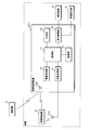
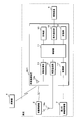
図1は本発明の実施形態1に係る車両用通信システムの一構成例を示す模式図である。本実施形態1に係る車両用通信システムは、無線通信に係るハードウェアを共用し、TPMS及びパッシブエントリシステムの無線通信システムを構成している。車両用通信システムは、車体の適宜箇所に設けられた車載通信装置1と、車両Cに取り付けられたタイヤ3のホイール夫々に設けられた車載無線機2と、パッシブエントリシステムに係る携帯機4と、TPMSに係る報知装置5とを備える。
図1は本発明の実施形態1に係る車両用通信システムの一構成例を示す模式図である。本実施形態1に係る車両用通信システムは、無線通信に係るハードウェアを共用し、TPMS及びパッシブエントリシステムの無線通信システムを構成している。車両用通信システムは、車体の適宜箇所に設けられた車載通信装置1と、車両Cに取り付けられたタイヤ3のホイール夫々に設けられた車載無線機2と、パッシブエントリシステムに係る携帯機4と、TPMSに係る報知装置5とを備える。
TPMSは車載通信装置1、車載無線機2及び報知装置5によって構成される。車載無線機2は、各ホイールに装着されるタイヤ3の空気圧を定期的に検出し、検出した空気圧をUHF(Ultra High Frequency)帯の電波により車載通信装置1へ送信する。車載通信装置1は各車載無線機2と無線通信を行うことにより、各タイヤ3の空気圧の情報を取得する。車載通信装置1には通信線を介して報知装置5が接続されており、車載通信装置1は取得した空気圧の情報を報知装置5へ送信する。報知装置5は車載通信装置1から送信された空気圧の情報を受信し、空気圧を報知する。また、報知装置5はタイヤ3の空気圧が所定の閾値未満である場合、警告を発する。
一方、パッシブエントリシステムは、車載通信装置1及び携帯機4によって構成される。車載通信装置1は、使用者が所持する携帯機4との間で無線通信を行い、携帯機4を認証し、該携帯機4の位置を検出する。車両Cのドアハンドルには図示しないタッチセンサが設けられており、タッチセンサによって使用者の手がドアハンドルに触れたことを検出した場合、又はドアスイッチが押された場合等、正規の携帯機4が車外に位置するとき、車載通信装置1は、車両Cのドアの施錠及び解錠等の処理を実行する。
なお、車両用通信システムを構成するパッシブエントリシステムは一例であり、携帯機4と、車載通信装置1との間で無線通信を行い、各種車両制御を行うシステムに本発明を適用することができる。例えば、車両用通信システムは、TPMSと共に、キーレスエントリシステム、メカニカルキーを用いること無く、車輌に搭載された原動機の始動を可能にするスマートスタートシステム等を構成しても良い。
なお、車両用通信システムを構成するパッシブエントリシステムは一例であり、携帯機4と、車載通信装置1との間で無線通信を行い、各種車両制御を行うシステムに本発明を適用することができる。例えば、車両用通信システムは、TPMSと共に、キーレスエントリシステム、メカニカルキーを用いること無く、車輌に搭載された原動機の始動を可能にするスマートスタートシステム等を構成しても良い。
図2は車載通信装置1の一構成例を示すブロック図である。車載通信装置1は、該車載通信装置1の各構成部の動作を制御する制御部11を備える。制御部11には、記憶部12、車載受信部13、車載送信部14、計時部15及び車内通信部16が接続されている。
制御部11は、例えば一又は複数のCPU(Central Processing Unit)、マルチコアCPU、ROM(Read Only Memory)、RAM(Random Access Memory)、入出力インタフェース等を有するマイコンである。制御部11のCPUは入出力インタフェースを介して記憶部12、車載受信部13、車載送信部14、計時部15及び車内通信部16に接続している。制御部11は記憶部12に記憶されている制御プログラムを実行することにより、各構成部の動作を制御し、タイヤ空気圧監視処理、ドアの施錠及び解錠処理、本実施形態に係る混信防止処理を実行する。
記憶部12は、EEPROM(Electrically Erasable Programmable ROM)、フラッシュメモリ等の不揮発性メモリである。記憶部12は、制御部11が車載通信装置1の各構成部の動作を制御することにより、タイヤ空気圧監視処理、ドアの施錠及び解錠処理、本実施形態に係る混信防止処理を実行するための制御プログラムを記憶している。
車載受信部13には、RFアンテナ13aが接続されている。車載受信部13は、車載無線機2又は携帯機4からRF帯の電波を用いて送信された信号を、RFアンテナ13aにて受信する。車載受信部13は、受信した信号を復調し、復調された信号を制御部11へ出力する回路である。搬送波としては300MHz~3GHzのUHF(Ultra High Frequency)帯を使用するが、この周波数帯に限定するものでは無い。
車載送信部14は、制御部11から出力された信号をLF帯の信号に変調し、変調された信号をLFアンテナ14aから車載無線機2又は携帯機4へ送信する回路である。搬送波としては30kHz~300kHzのLF(Low Frequency)帯を使用するが、この周波数帯に限定するものでは無い。
計時部15は、例えばタイマ、リアルタイムクロック等により構成され、制御部11の制御に従って計時を開始し、計時結果を制御部11に与える。
車内通信部16は、CAN(Controller Area Network)又はLIN(Local Interconnect Network)等の通信プロトコルに従って通信を行う通信回路であり、タイヤ3の空気圧に係る情報を報知装置5へ送信する。
報知装置5は、例えば、車内通信部16から送信されたタイヤ3の空気圧に係る情報を画像又は音声によって報知する表示部又はスピーカを備えたオーディオ機器、インスツルメントパネルの計器に設けられた表示部等である。表示部は液晶ディスプレイ、有機ELディスプレイ、ヘッドアップディスプレイ等である。例えば、報知装置5は、車両Cに設けられた各タイヤ3の空気圧を表示する。
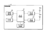
図3は車載無線機2の一構成例を示すブロック図である。車載無線機2は、該車載無線機2の各構成部の動作を制御するセンサ制御部21を備える。センサ制御部21には、センサ用記憶部22、センサ送信部23、センサ受信部24、空気圧検出部25及び計時部26が接続されている。
センサ制御部21は、例えば一又は複数のCPU、マルチコアCPU、ROM、RAM、入出力インタフェース等を有するマイコンである。センサ制御部21のCPUは入出力インタフェースを介してセンサ用記憶部22、センサ送信部23、センサ受信部24、空気圧検出部25及び計時部26に接続している。センサ制御部21はセンサ用記憶部22に記憶されている制御プログラムを読み出し、各部を制御する。車載無線機2は、図示しない電池を備え、当該電池からの電力により動作する。
センサ用記憶部22は不揮発性メモリである。センサ用記憶部22には、センサ制御部21のCPUがタイヤ3の空気圧の検出及び送信に係る処理を行うための制御プログラムが記憶されている。
空気圧検出部25は、例えばダイヤフラムを備え、圧力の大きさによって変化するダイヤフラムの変形量に基づき、タイヤ3の空気圧を検出する。該空気圧は絶対圧である。絶対圧は、絶対真空を基準にした圧力の大きさである。なお、本実施形態において、空気圧検出部25が検出する空気圧は、絶対圧であることを説明したが、ゲージ圧、所定の基準圧に対する圧力の大きさを示す差圧を検出する構成としてもよい。所定の基準圧は、例えばタイヤ3の状態が点検を必要としない状態における空気圧の範囲の中央値、下限値、又は上限値等である。
空気圧検出部25は検出したタイヤ3の空気圧を示す信号をセンサ制御部21へ出力する。センサ制御部21は、制御プログラムを実行することにより、タイヤ3の空気圧、車載無線機2に固有の装置ID等の情報を含む信号を生成し、センサ送信部23へ出力する。
空気圧検出部25は検出したタイヤ3の空気圧を示す信号をセンサ制御部21へ出力する。センサ制御部21は、制御プログラムを実行することにより、タイヤ3の空気圧、車載無線機2に固有の装置ID等の情報を含む信号を生成し、センサ送信部23へ出力する。
センサ送信部23には、RFアンテナ23aが接続されている。センサ送信部23は、センサ制御部21が生成した信号をUHF帯の信号に変調し、変調した信号を、RFアンテナ23aを用いて送信する。
センサ受信部24には、LFアンテナ24aが接続されている。センサ受信部24は、車載通信装置1からLF帯の電波を用いて送信された信号を、LFアンテナ24aにて受信し、受信した信号をセンサ制御部21へ出力する。
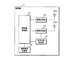
図4は携帯機4の一構成例を示すブロック図である。携帯機4は、該携帯機4の各構成部の動作を制御する携帯機制御部41を備える。携帯機制御部41には、携帯機用記憶部42、携帯送信部43、携帯受信部44及び信号強度測定部45が接続されている。
携帯機制御部41は、例えば一又は複数のCPU、マルチコアCPU、ROM、RAM、入出力インタフェース等を有するマイコンである。携帯機制御部41のCPUは入出力インタフェースを介して携帯機用記憶部42、携帯送信部43、携帯受信部44及び信号強度測定部45に接続している。携帯機制御部41は携帯機用記憶部42に記憶されている制御プログラムを読み出し、各部を制御する。
携帯機用記憶部42は不揮発性メモリである。携帯機用記憶部42は、携帯機制御部41が携帯機4の各構成部の動作を制御することにより、携帯機4の位置検出を行うための情報を含む信号等を車載通信装置1へ送信する処理を実行するための制御プログラムを記憶している。
携帯受信部44はLFアンテナ44aに接続されており、車載通信装置1からLF帯の電波を用いて送信された各種信号を受信し、受信した信号を携帯機制御部41へ出力する。
受信信号強度検出部は、LFアンテナ44aが受信した信号の受信信号強度を検出し、検出した受信信号強度を携帯機制御部41へ出力する回路である。
携帯送信部43はRFアンテナ43aに接続されており、携帯機制御部41から出力された信号をRF帯の信号に変調し、変調した信号をRFアンテナ43aから送信する。携帯送信部43はUHF帯の電波を用いて信号を送信する。
次に、車載無線機2及び携帯機4から送信された信号の混信防止に係る処理手順を説明する。実施形態1においては、車載無線機2は、所定の送信頻度で定期的にタイヤ3の空気圧に係る信号を自立的に送信しているものとする。
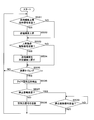
図5は実施形態1に係る車載通信装置1の処理手順を示すフローチャートである。車載通信装置1は、車載受信部13にて信号を受信したか否かを判定する(ステップS11)。信号を受信していないと判定した場合(ステップS11:NO)、制御部11は処理をステップS11へ戻し、信号の受信状態を監視する。
図5は実施形態1に係る車載通信装置1の処理手順を示すフローチャートである。車載通信装置1は、車載受信部13にて信号を受信したか否かを判定する(ステップS11)。信号を受信していないと判定した場合(ステップS11:NO)、制御部11は処理をステップS11へ戻し、信号の受信状態を監視する。
信号を受信したと判定した場合(ステップS11:YES)、制御部11は、受信処理を開始し(ステップS12)、混信が生じているか否かを判定する(ステップS13)。混信の有無は、例えば受信した信号から意味のある情報を抽出できるか否かに基づいて判定すれば良い。混信は、車載無線機2と、携帯機4とから信号が同時的に送信された場合に生ずる。混信が生じていると判定した場合(ステップS13:YES)、制御部11は、信号の送信の停止を指示する停止信号を、車載送信部14にて車載無線機2へ送信し(ステップS14)、処理をステップS13へ戻す。後述するように停止信号を受信した車載無線機2は信号の送信を停止する。
混信が生じていないと判定した場合(ステップS13:NO)、制御部11は、携帯機4又は車載無線機2から送信された信号の受信処理を実行する(ステップS15)。特に混信が生じていない場合、車載無線機2又は携帯機4から送信された信号の受信処理が行われる。混信が生じた後、車載無線機2が信号の送信を停止している場合、制御部11は携帯機4から送信された信号を受信することになる。
次いで、制御部11は、信号の受信処理を完了したか否かを判定する(ステップS16)。携帯機4又は車載無線機2からの信号の受信を完了していないと判定した場合(ステップS16:NO)、制御部11は処理をステップS13へ戻し、受信処理を継続する。
受信処理を完了したと判定した場合(ステップS16:YES)、制御部11は、車載無線機2からの信号の送信を停止させる処理を実行中であるか否かを判定する(ステップS17)。車載無線機2からの信号の送信を停止させる処理を実行していないと判定した場合(ステップS17::NO)、制御部11は処理をステップS11へ戻す。車載無線機2からの信号の送信を停止させる処理を実行中であると判定した場合(ステップS17:YES)、制御部11は、送信停止処理の解除を指示する停止信号を、車載送信部14にて車載無線機2へ送信し(ステップS18)、処理をステップS11へ戻す。後述するように停止解除信号を受信した車載無線機2は信号の送信を再開する。
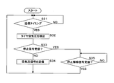
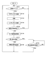
図6は実施形態1に係る車載無線機2の処理手順を示すフローチャートである。車載無線機2のセンサ制御部21は、計時部26の計時結果を参照し、タイヤ3の空気圧を示す信号の送信タイミングであるか否かを判定する(ステップS31)。車載無線機2は、例えば60秒間に1回の送信頻度で、タイヤ3の空気圧に係る信号を車載通信装置1へ送信する。送信タイミングで無いと判定した場合(ステップS31:NO)、センサ制御部21は処理をステップS31へ戻し、送信タイミングが到来するまで、待機する。
送信タイミングであると判定した場合(ステップS31:YES)、センサ制御部21は、空気圧検出部25にてタイヤ3の空気圧を検出する(ステップS32)。次いで、センサ制御部21は、センサ受信部24にて停止信号を受信したか否かを判定する(ステップS33)。停止信号を受信していないと判定した場合(ステップS33:NO)、センサ制御部21は、検出した空気圧を示す信号を、センサ送信部23にて車載通信装置1へ送信し(ステップS34)、処理をステップS31へ戻す。
停止信号を受信したと判定した場合(ステップS33:YES)、その後、センサ制御部21は停止解除信号を受信したか否かを判定する(ステップS35)。停止解除信号を受信していないと判定した場合(ステップS35:NO)、センサ制御部21は、処理をステップS35へ戻し、停止解除信号を受信するまで待機する。つまり、タイヤ3の空気圧の検出及び検出した空気圧を示す信号の送信処理を停止する。停止解除信号を受信した場合(ステップS35:YES)、センサ制御部21は、処理をステップS31へ戻し、空気圧の検出及び該空気圧を示す信号の送信処理を再開する。
このように構成された車両用通信システムによれば、車載無線機2及び携帯機4から同時的に信号が送信されて混信が生じた場合、車載通信装置1は、停止信号を車載無線機2へ送信することによって、車載無線機2からの信号の送信を停止させ、混信が生じない状態にすることができる。車載通信装置1は、車載無線機2からの信号の送信を一時的に停止させることにより、携帯機4から送信された信号を受信することができる。従って、TPMSを構成する車載無線機2と、パッシブエントリシステムを構成する携帯機4とから送信される信号が混信することを防止し、携帯機4から送信された信号を受信することができる。
そして、車載通信装置1は、携帯機4からの信号の受信を完了した後、解除信号を車載無線機2へ送信することによって信号の送信を再開させることができる。車載通信装置1は、車載無線機2から送信されるタイヤ3の空気圧に係る信号を受信することができる。
(実施形態2)
実施形態2に係る車両用通信システムの構成は実施形態1と同様であり、信号停止処理の解除手順が実施形態1と異なるため、以下では、主にかかる相違点を説明する。その他の構成及び作用効果は実施形態1と同様であるため、対応する箇所には同様の符号を付して詳細な説明を省略する。
実施形態1に係る車載通信装置1は、停止信号の送信後、携帯機4からの信号の受信処理を完了した際、停止解除信号を車載無線機2へ送信し、信号の送信を再開させる構成であるが、実施形態2に係る車載無線機2は自立的に信号の送信を再開する構成である。
実施形態2に係る車両用通信システムの構成は実施形態1と同様であり、信号停止処理の解除手順が実施形態1と異なるため、以下では、主にかかる相違点を説明する。その他の構成及び作用効果は実施形態1と同様であるため、対応する箇所には同様の符号を付して詳細な説明を省略する。
実施形態1に係る車載通信装置1は、停止信号の送信後、携帯機4からの信号の受信処理を完了した際、停止解除信号を車載無線機2へ送信し、信号の送信を再開させる構成であるが、実施形態2に係る車載無線機2は自立的に信号の送信を再開する構成である。
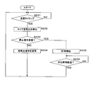
図7は実施形態2に係る車載無線機2の処理手順を示すフローチャートである。実施形態2に係る車載無線機2のセンサ制御部21は、実施形態1のステップS31~ステップS34と同様の処理をステップS231~ステップS234で実行する。ステップS233において、センサ制御部21は、センサ受信部24にて停止信号を受信したか否かを判定する(ステップS233)。停止信号を受信したと判定した場合(ステップS233:YES)、センサ制御部21は、計時部26にて計時を開始する(ステップS235)。そして、センサ制御部21は、計時開始後、所定時間が経過したか否かを判定する(ステップS236)。所定時間が経過していないと判定した場合(ステップS236:NO)、センサ制御部21は、処理をステップS236へ戻し、所定時間が経過するまで待機する。所定時間が経過したと判定した場合(ステップS236:YES)、センサ制御部21は、処理をステップS231へ戻し、空気圧の検出及び該空気圧を示す信号の送信処理を再開する。
実施形態2に係る車両用通信システムによれば、車載通信装置1は、停止信号を車載無線機2へ送信することによって、車載無線機2からの信号の送信を停止させ、混信が生じない状態で携帯機4からの信号を受信することができる。その後、所定時間が経過すると車載無線機2は信号の送信を自立的に再開し、車載通信装置1は車載無線機2から送信されるタイヤ3の空気圧に係る信号を受信することができる。
従って、TPMSを構成する車載無線機2と、パッシブエントリシステムを構成している携帯機4とから送信される信号が混信することを防止することができる。また、車載通信装置1は解除信号を送信しなくても、車載無線機2による信号の送信を再開させることができる。
従って、TPMSを構成する車載無線機2と、パッシブエントリシステムを構成している携帯機4とから送信される信号が混信することを防止することができる。また、車載通信装置1は解除信号を送信しなくても、車載無線機2による信号の送信を再開させることができる。
(実施形態3)
実施形態3に係る車両用通信システムの構成は実施形態1と同様であり、混信発生時に受信した情報を破棄する処理が実施形態1と異なるため、以下では、主にかかる相違点を説明する。その他の構成及び作用効果は実施形態1と同様であるため、対応する箇所には同様の符号を付して詳細な説明を省略する。
実施形態3に係る車両用通信システムの構成は実施形態1と同様であり、混信発生時に受信した情報を破棄する処理が実施形態1と異なるため、以下では、主にかかる相違点を説明する。その他の構成及び作用効果は実施形態1と同様であるため、対応する箇所には同様の符号を付して詳細な説明を省略する。
図8は実施形態3に係る車載通信装置1の処理手順を示すフローチャートである。実施形態2に係る車載通信装置1の制御部11は、実施形態1のステップS11~ステップS14と同様の処理をステップS311~ステップS314で実行する。混信が生じていると判定した場合(ステップS313:YES)、実施形態3に係る制御部11は、信号の送信の停止を指示する停止信号を、車載送信部14にて車載無線機2へ送信し(ステップS314)、混信発生時に受信処理を行って得た情報を破棄し(ステップS315)、処理をステップS313へ戻す。
混信が生じていないと判定した場合(ステップS313:NO)、制御部11は、実施形態1のステップS15~S18と同様の処理をステップS316~ステップS319で実行する。
混信が生じていないと判定した場合(ステップS313:NO)、制御部11は、実施形態1のステップS15~S18と同様の処理をステップS316~ステップS319で実行する。
実施形態3に係る車両用通信システムによれば、車載通信装置1は、混信が発生したときに車載受信部13が受信した信号の情報を削除するため、混信によって誤った情報を受信することを防ぐことができる。
なお、本実施形態3を実施形態1の変形例として説明したが、本実施形態2及び3を組み合わせて車両用通信システムを構成しても良い。
(実施形態4)
実施形態4に係る車両用通信システムの構成は実施形態1と同様であり、車載通信装置1からの要求に応じて車載無線機2がタイヤ3の空気圧を示す信号を送信する点が実施形態1と異なるため、以下では、主にかかる相違点を説明する。その他の構成及び作用効果は実施形態1と同様であるため、対応する箇所には同様の符号を付して詳細な説明を省略する。
実施形態4に係る車両用通信システムの構成は実施形態1と同様であり、車載通信装置1からの要求に応じて車載無線機2がタイヤ3の空気圧を示す信号を送信する点が実施形態1と異なるため、以下では、主にかかる相違点を説明する。その他の構成及び作用効果は実施形態1と同様であるため、対応する箇所には同様の符号を付して詳細な説明を省略する。
図9は実施形態4に係る車載通信装置1の処理手順を示すフローチャートである。車載通信装置1の制御部11は、計時部15の計時結果を参照し、タイヤ3の空気圧を示す信号の送信タイミングであるか否かを判定する(ステップS411)。送信タイミングで無いと判定した場合(ステップS411:NO)、制御部11は処理をステップS411へ戻し、送信タイミングが到来するまで、待機する。
送信タイミングであると判定した場合(ステップS411:YES)、制御部11は、タイヤ3の空気圧を示した信号の送信を要求する要求信号を、車載送信部14にて車載無線機2へ送信する(ステップS412)。ステップS411~ステップS412の処理によって、車載通信装置1から車載無線機2へ所定の送信頻度で要求信号が送信されることになる。
次いで、制御部11は、車載受信部13にて信号を受信したか否かを判定する(ステップS413)。信号を受信していないと判定した場合(ステップS413:NO)、制御部11は処理をステップS413へ戻し、信号の受信状態を監視する。
信号を受信したと判定した場合(ステップS413:YES)、制御部11は、受信処理を開始し(ステップS414)、混信が生じているか否かを判定する(ステップS415)。混信が生じていると判定した場合(ステップS415:YES)、制御部11は、信号の送信の停止を指示する停止信号を、車載送信部14にて車載無線機2へ送信し(ステップS416)、処理をステップS415へ戻し、受信処理を継続する。
混信が生じていないと判定した場合(ステップS415:NO)、制御部11は、携帯機4又は車載無線機2から送信された信号の受信処理を実行する(ステップS417)。次いで、制御部11は、信号の受信処理を完了したか否かを判定する(ステップS418)。携帯機4又は車載無線機2からの信号の受信を完了していないと判定した場合(ステップS418:NO)、制御部11は処理をステップS415へ戻す。受信処理を完了したと判定した場合(ステップS418:YES)、制御部11は、処理をステップS411へ戻す。
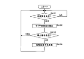
図10は実施形態4に係る車載無線機2の処理手順を示すフローチャートである。車載無線機2のセンサ制御部21は、車載通信装置1から送信された要求信号を受信したか否かを判定する(ステップS431)。要求信号を受信していないと判定した場合(ステップS431:NO)、センサ制御部21は処理をステップS431へ戻し、要求信号を受信するまで待機する。
要求信号を受信したと判定した場合(ステップS431:YES)、センサ制御部21は、空気圧検出部25にてタイヤ3の空気圧を検出する(ステップS432)。次いで、センサ制御部21は、センサ受信部24にて停止信号を受信したか否かを判定する(ステップS433)。停止信号を受信していないと判定した場合(ステップS433:NO)、センサ制御部21は、検出した空気圧を示す信号を、センサ送信部23にて車載通信装置1へ送信し(ステップS434)、処理をステップS431へ戻す。
停止信号を受信したと判定した場合(ステップS433:YES)、空気圧を示す信号の送信を行わず、センサ制御部21は、処理をステップS431へ戻す。次に車載通信装置1から要求信号が送信されるまで車載無線機2からタイヤ3の空気圧を示す信号は送信されない。
このように構成された実施形態4に係る車両用通信システムによれば、車載通信装置1からの要求に応じて、車載無線機2がタイヤ3の空気圧に係る信号を送信し、車載通信装置1は、該信号を受信する。車載通信装置1は、車載無線機2へ信号の送信を要求したものの、携帯機4からの信号によって混信が生ずるおそれがある場合、直ちに停止信号を車載無線機2へ送信することによって、車載無線機2からの信号の送信を停止させる。そして、車載通信装置1は、混信が生じない状態で、携帯機4からの信号を受信することができる。
従って、TPMSを構成する車載無線機2と、パッシブエントリシステムを構成している携帯機4とから送信される信号が混信することを防止することができる。
従って、TPMSを構成する車載無線機2と、パッシブエントリシステムを構成している携帯機4とから送信される信号が混信することを防止することができる。
なお、実施形態4を実施形態1の変形例として説明したが、本実施形態3及び4を組み合わせて車両用通信システムを構成しても良い。
(実施形態5)
実施形態5に係る車両用通信システムの構成は実施形態1と同様であり、車両Cの速度に応じた混信時の処理内容が実施形態1と異なるため、以下では、主にかかる相違点を説明する。その他の構成及び作用効果は実施形態1と同様であるため、対応する箇所には同様の符号を付して詳細な説明を省略する。
実施形態5に係る車両用通信システムの構成は実施形態1と同様であり、車両Cの速度に応じた混信時の処理内容が実施形態1と異なるため、以下では、主にかかる相違点を説明する。その他の構成及び作用効果は実施形態1と同様であるため、対応する箇所には同様の符号を付して詳細な説明を省略する。
図11は実施形態5に係る車載通信装置501の一構成例を示すブロック図である。実施形態5に係る車載通信装置501は、実施形態1と同様、制御部11、記憶部12、車載送信部14、車載受信部13、計時部15及び車内通信部16を備える。車内通信部16には、報知装置5に加え、車速検出部6が接続されている。
車速検出部6は、例えば車両Cに備えられた車軸の回転数に比例した信号を発信する磁気ピックアップ、ホール素子等を備えた非接触センサ、及び該非接触センサからのパルス数を計測する計数回路を備え、パルス数を計測することによって車両Cの速度を検出する。車速検出部6は、車両Cの速度を示した車速情報を車内通信部16へ出力し、制御部11は、車速検出部6にて車速情報を取得する。
非接触センサは速度検出部の一例であり、かかる構造に限定されるものでは無い。例えば、GPSにて検出された車両Cの位置情報に基づいて、車両Cの速度を検出するように車速検出部6を構成しても良い。
非接触センサは速度検出部の一例であり、かかる構造に限定されるものでは無い。例えば、GPSにて検出された車両Cの位置情報に基づいて、車両Cの速度を検出するように車速検出部6を構成しても良い。
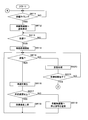
図12及び図13は実施形態5に係る車載通信装置501の処理手順を示すフローチャートである。実施形態5においては、車載無線機2は、所定の送信頻度で定期的にタイヤ3の空気圧に係る信号を自立的に送信しており、車載通信装置501からの指示により、信号の送信頻度を変更するように構成されている。
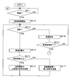
車載通信装置501は、車載受信部13にて信号を受信したか否かを判定する(ステップS511)。信号を受信していないと判定した場合(ステップS511:NO)、制御部11は処理をステップS511へ戻し、信号の受信状態を監視する。信号を受信したと判定した場合(ステップS511:YES)、制御部11は、受信処理を開始し(ステップS512)、混信が生じているか否かを判定する(ステップS513)。混信が生じていると判定した場合(ステップS513:YES)、制御部11は、車速検出部6にて車速を検出し(ステップS514)、検出した車速が所定速度以上であるか否かを判定する(ステップS515)。
車載通信装置501は、車載受信部13にて信号を受信したか否かを判定する(ステップS511)。信号を受信していないと判定した場合(ステップS511:NO)、制御部11は処理をステップS511へ戻し、信号の受信状態を監視する。信号を受信したと判定した場合(ステップS511:YES)、制御部11は、受信処理を開始し(ステップS512)、混信が生じているか否かを判定する(ステップS513)。混信が生じていると判定した場合(ステップS513:YES)、制御部11は、車速検出部6にて車速を検出し(ステップS514)、検出した車速が所定速度以上であるか否かを判定する(ステップS515)。
車速が所定速度以上であると判定した場合(ステップS515:YES)、制御部11は、タイヤ3の空気圧を示す信号の送信頻度を上昇させる上昇指示信号を、車載送信部14にて車載無線機2へ送信し(ステップS516)、処理をステップS513へ戻す。
車速が所定速度未満であると判定した場合(ステップS515:NO)、制御部11は、停止信号を、車載送信部14にて車載無線機2へ送信し(ステップS517)、処理をステップS513へ戻す。
車速が所定速度未満であると判定した場合(ステップS515:NO)、制御部11は、停止信号を、車載送信部14にて車載無線機2へ送信し(ステップS517)、処理をステップS513へ戻す。
混信が生じていないと判定した場合(ステップS513:NO)、制御部11は、携帯機4又は車載無線機2から送信された信号の受信処理を実行する(ステップS518)。次いで、制御部11は、信号の受信処理を完了したか否かを判定する(ステップS519)。携帯機4又は車載無線機2からの信号の受信を完了していないと判定した場合(ステップS519:NO)、制御部11は処理をステップS513へ戻し、受信処理を継続する。
受信処理を完了したと判定した場合(ステップS519:YES)、制御部11は、車載無線機2からの信号の送信を停止させる処理を実行中であるか否かを判定する(ステップS520)。車載無線機2からの信号の送信を停止させる処理を実行中であると判定した場合(ステップS520:YES)、制御部11は、送信停止処理の解除を指示する停止信号を、車載送信部14にて車載無線機2へ送信する(ステップS521)。
ステップS521の処理を終えた場合、又は車載無線機2からの信号の送信を停止させる処理を実行していないと判定した場合(ステップS520:NO)、制御部11は、タイヤ3の空気圧を示す信号を高頻度で送信させる処理の実行中であるか否かを判定する(ステップS522)。タイヤ3の空気圧を示す信号を高頻度で送信させる処理の実行中で無いと判定した場合(ステップS522:NO)、制御部11は、処理をステップS511へ戻す。タイヤ3の空気圧を示す信号を高頻度で送信させる処理の実行中であると判定した場合(ステップS522:YES)、制御部11は、車速検出部6にて車速を検出し(ステップS523)、車速が所定速度未満であるか否かを判定する(ステップS524)。車速が所定速度以上であると判定した場合(ステップS524:NO)、制御部11は処理をステップS511へ戻す。車速が所定速度未満であると判定した場合(ステップS524:YES)、制御部11は、タイヤ3の空気圧を示す信号を高頻度で送信させる処理の解除を示す上昇指示解除信号を、車載送信部14にて車載無線機2へ送信し(ステップS525)、処理をステップS511へ戻す。
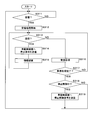
図14は実施形態5に係る車載無線機2の処理手順を示すフローチャートである。車載無線機2のセンサ制御部21は、センサ受信部24にて送信頻度の上昇指示信号を受信したか否かを判定する(ステップS531)。上昇指示信号を受信したと判定した場合(ステップS531:YES)、センサ制御部21は、タイヤ3の空気圧を示す信号の送信頻度を上昇させる(ステップS532)。
ステップS532の処理を終えた場合、又は上昇指示信号を受信していないと判定した場合(ステップS531:NO)、センサ制御部21は、上昇指示解除信号を受信したか否かを判定する(ステップS533)。上昇指示解除信号を受信したと判定した場合(ステップS533:YES)、センサ制御部21は、タイヤ3の空気圧を示す信号の送信頻度を上昇前の所定の送信頻度に戻す(ステップS534)。
ステップS534の処理を終えた場合、又は上昇指示解除信号を受信していないと判定した場合(ステップS533:NO)、センサ制御部21は、実施形態1におけるステップS31~ステップS35と同様の処理を、ステップS535~ステップS539にて実行する。
このように構成された実施形態4に係る車両用通信システムによれば、車両Cの速度が所定速度以上で、混信が生じた場合、車載通信装置501は、タイヤ3の空気圧に係る信号をより高頻度で送信させることにより、該信号の受信成功確率を上昇させることができる。車両Cの速度が所定速度以上である場合、携帯機4からの信号よりも、タイヤ3の空気圧に係る信号の方が重要であるところ、車載通信装置501は、タイヤ3の空気圧の情報をより確実に取得することができる。
車両Cの速度が所定速度未満で、混信が生じた場合、実施形態1と同様、車載通信装置501は、停止信号を車載無線機2へ送信することによって、車載無線機2からの信号の送信を停止させ、混信が生じない状態で携帯機4から送信された信号を受信することができる。
車両Cの速度が所定速度未満でタイヤ3の空気圧の重要性が低いため、車載通信装置501は、携帯機4からの信号を優先的に受信し、その後車載無線機2からの信号を受信することができる。
このように、TPMSを構成する車載無線機2と、パッシブエントリシステムを構成する携帯機4とから送信される信号が混信することを防止すると共に、車載通信装置501は、重要な情報を有する信号を優先的に受信することができる。
車両Cの速度が所定速度未満でタイヤ3の空気圧の重要性が低いため、車載通信装置501は、携帯機4からの信号を優先的に受信し、その後車載無線機2からの信号を受信することができる。
このように、TPMSを構成する車載無線機2と、パッシブエントリシステムを構成する携帯機4とから送信される信号が混信することを防止すると共に、車載通信装置501は、重要な情報を有する信号を優先的に受信することができる。
なお、実施形態5を実施形態1の変形例として説明したが、本実施形態2及び5を組み合わせて車両用通信システムを構成しても良いし、本実施形態3及び5を組み合わせて車両用通信システムを構成しても良い。
(実施形態6)
実施形態6に係る車両用通信システムの構成は実施形態4と同様であり、車両Cの速度に応じた混信時の処理内容が実施形態4と異なるため、以下では、主にかかる相違点を説明する。その他の構成及び作用効果は実施形態4と同様であるため、対応する箇所には同様の符号を付して詳細な説明を省略する。
実施形態6に係る車両用通信システムは、実施形態4と同様、タイヤ3の空気圧の検出及び送信タイミングを、車載通信装置1が制御しており、混信発生時の処理内容は実施形態5と同様である。
実施形態6に係る車両用通信システムの構成は実施形態4と同様であり、車両Cの速度に応じた混信時の処理内容が実施形態4と異なるため、以下では、主にかかる相違点を説明する。その他の構成及び作用効果は実施形態4と同様であるため、対応する箇所には同様の符号を付して詳細な説明を省略する。
実施形態6に係る車両用通信システムは、実施形態4と同様、タイヤ3の空気圧の検出及び送信タイミングを、車載通信装置1が制御しており、混信発生時の処理内容は実施形態5と同様である。
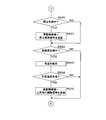
図15及び図16は実施形態6に係る車載通信装置1の処理手順を示すフローチャートである。車載通信装置1の制御部11は、実施形態4におけるステップS411~ステップS415と同様の処理をステップS611~ステップS615にて実行する。ステップS615において、混信が生じていると判定した場合(ステップS615:YES)、制御部11は、車速検出部6にて車速を検出し(ステップS616)、車速が所定速度以上であるか否かを判定する(ステップS617)。車速が所定速度以上であると判定した場合(ステップS617:YES)、制御部11は、車速に応じて要求信号の送信頻度を上昇させ(ステップS618)、処理をステップS615に戻す。通常時において車載通信装置1は、所定の送信頻度で要求信号を車載無線機2へ送信しているが、ステップS618の処理によって、要求信号の送信頻度が上昇する。このため、タイヤ3の空気圧を示す信号の受信成功確率が上昇する。
車速が所定速度未満であると判定した場合(ステップS617:NO)、制御部11は、停止信号を、車載送信部14にて車載無線機2へ送信し(ステップS619)、処理をステップS615へ戻し、受信処理を継続する。
ステップS615において、混信が生じていないと判定した場合(ステップS615:NO)、制御部11は、携帯機4又は車載無線機2から送信された信号の受信処理を実行する(ステップS620)。次いで、制御部11は、信号の受信処理を完了したか否かを判定する(ステップS621)。携帯機4又は車載無線機2からの信号の受信を完了していないと判定した場合(ステップS621:NO)、制御部11は処理をステップS615へ戻す。
受信処理を完了したと判定した場合(ステップS621:YES)、制御部11は、要求信号を高頻度で送信する処理を実行中であるか否かを判定する(ステップS622)。要求信号を高頻度で送信する処理を実行していないと判定した場合(ステップS622:NO)、制御部11は、処理をステップS611へ戻す。要求信号を高頻度で送信する処理を実行していると判定した場合(ステップS622:YES)、制御部11は、車速検出部6にて車速を検出し(ステップS623)、車速が所定速度未満であるか否かを判定する(ステップS624)。
車速が所定速度以上であると判定した場合(ステップS624:NO)、制御部11は処理をステップS611へ戻す。車速が所定速度未満であると判定した場合(ステップS624:YES)、制御部11は、要求信号の送信頻度を上昇前の所定の送信頻度に戻し(ステップS625)、処理をステップS611へ戻す。
実施形態6に係る車両用通信システムによれば、車両Cの速度が所定速度以上で、混信が生じた場合、車載通信装置1は、より高頻度で車載無線機2へ要求信号を送信することによって、タイヤ3の空気圧に係る信号をより高頻度で送信させることができ、該信号の受信成功確率を上昇させることができる。車両Cの速度が所定速度以上である場合、携帯機4からの信号よりも、タイヤ3の空気圧に係る信号の方が重要であるところ、車載通信装置1は、タイヤ3の空気圧の情報をより確実に取得することができる。
車載無線機2へ信号の送信を要求したものの、車両Cの速度が所定速度未満で、混信が生じた場合、実施形態4と同様、車載通信装置1は、直ちに停止信号を車載無線機2へ送信することによって、車載無線機2からの信号の送信を停止させる。そして、車載通信装置1は、混信が生じない状態で、携帯機4からの信号を受信することができる。
このように、TPMSを構成する車載無線機2と、パッシブエントリシステムを構成する携帯機4とから送信される信号が混信することを防止すると共に、車載通信装置1は、重要な情報を有する信号を優先的に受信することができる。
このように、TPMSを構成する車載無線機2と、パッシブエントリシステムを構成する携帯機4とから送信される信号が混信することを防止すると共に、車載通信装置1は、重要な情報を有する信号を優先的に受信することができる。
なお、実施形態6を実施形態4の変形例として説明したが、本実施形態3及び6を組み合わせて車両用通信システムを構成しても良い。
(実施形態7)
実施形態7に係る車両用通信システムの構成は実施形態1と同様であり、車載無線機2の構成及び処理手順が実施形態1と異なるため、以下では、主にかかる相違点を説明する。その他の構成及び作用効果は実施形態1と同様であるため、対応する箇所には同様の符号を付して詳細な説明を省略する。
実施形態7に係る車両用通信システムの構成は実施形態1と同様であり、車載無線機2の構成及び処理手順が実施形態1と異なるため、以下では、主にかかる相違点を説明する。その他の構成及び作用効果は実施形態1と同様であるため、対応する箇所には同様の符号を付して詳細な説明を省略する。
図17は実施形態7に係る車載無線機2の一構成例を示すブロック図である。実施形態7に係る車載無線機2は、実施形態1と同様、センサ制御部21、センサ用記憶部22、センサ送信部23、センサ受信部24、空気圧検出部25及び計時部26を備える。更に、車載無線機2は、信号を受信するアンテナは、RFアンテナ23a又はLFアンテナ24aに切り替える切替部27を備える。切替部27による受信アンテナの切り替えはセンサ制御部21により制御される。車載無線機2は、通常、RFアンテナ23aを用いて信号を送信し、LFアンテナ24aを用いて信号を受信するが、切替部27によって、受信アンテナをRFアンテナ23aに切り替えることができる。受信アンテナをRFアンテナ23aに切り替えることによって、車載無線機2は車両C周辺を伝搬しているUHF帯の信号を受信することができる。
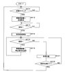
図18は実施形態7に係る車載無線機2の処理手順を示すフローチャートである。車載無線機2のセンサ制御部21は、計時部26の計時結果を参照し、タイヤ3の空気圧を示す信号の送信タイミングであるか否かを判定する(ステップS731)。送信タイミングで無いと判定した場合(ステップS731:NO)、センサ制御部21は処理をステップS731へ戻し、送信タイミングが到来するまで、待機する。
送信タイミングであると判定した場合(ステップS731:YES)、センサ制御部21は、信号の受信に使用するアンテナをRFアンテナ23aに切り替え(ステップS732)、RFアンテナ23aを用いて信号を受信する(ステップS733)。受信アンテナをRFアンテナ23aに切り替えることによって、UHF帯の信号、例えば、携帯機4から送信される信号の存在を確認することができる。そして、信号の受信に使用するアンテナを元のLFアンテナ24aに切り替える(ステップS734)。
次いで、センサ制御部21は、ステップS733の受信結果に基づいて、車載無線機2から送信される信号と、携帯機4から送信される信号とが混信する可能性があるか否かを判定する(ステップS735)。センサ制御部21は、ステップS733の処理で何らかの信号を受信した場合、混信する可能性があると判断すれば良い。混信の可能性があると判定した場合(ステップS735:YES)、センサ制御部21は、処理をステップS731へ戻す。
混信の可能性が無いと判定した場合(ステップS735:NO)、センサ制御部21は、実施形態1におけるステップS32~ステップS35と同様の処理を、以下のステップS736~739にて実行する。
このように構成された実施形態7に係る車両用通信システムによれば、車載無線機2は、UHF帯の信号を監視しており、UHF帯の信号が無いときにタイヤ3の空気圧に係る信号を送信し、UHF帯の信号が存在している場合、信号の送信を停止する。従って、車載通信装置701は、混信が生じる可能性が低い状況で車載無線機2から送信された信号を受信することができる。よって、TPMSを構成する車載無線機2と、パッシブエントリシステムを構成する携帯機4とから送信される信号が混信することをより効果的に防止し、車載無線機2及び携帯機4から送信された信号を受信することができる。
なお、実施形態7を実施形態1の変形例として説明したが、本実施形態1~6に本実施形態7に係る車載無線機2の構成を組み合わせて車両用通信システムを構成しても良い。
(実施形態8)
実施形態8に係る車両用通信システムの構成は実施形態4と同様であり、有線接続された第2の車載無線機7を備える点が実施形態4と異なるため、以下では、主にかかる相違点を説明する。その他の構成及び作用効果は実施形態4と同様であるため、対応する箇所には同様の符号を付して詳細な説明を省略する。
実施形態8に係る車両用通信システムの構成は実施形態4と同様であり、有線接続された第2の車載無線機7を備える点が実施形態4と異なるため、以下では、主にかかる相違点を説明する。その他の構成及び作用効果は実施形態4と同様であるため、対応する箇所には同様の符号を付して詳細な説明を省略する。
図19は実施形態8に係る車載通信装置801の一構成例を示すブロック図である。実施形態8に係る車載通信装置801は、実施形態1と同様の構成であり、更に駆動部17を備える。駆動部17には、第2の車載無線機7が接続されている。制御部11は、駆動部17にて要求信号を第2の車載無線機7へ有線送信する。第2の車載無線機7は、該要求信号を受信した場合、前記要求信号に応じた信号を車載受信部13へUHF帯で無線送信する。
このように構成された実施形態8に係る車両用通信システムにおいても、実施形態4と同様の作用効果を奏し、TPMSを構成する車載無線機2と、パッシブエントリシステムを構成している携帯機4とから送信される信号が混信することを防止することができる。
なお、実施形態8を実施形態4の変形例として説明したが、その他の本実施形態に本実施形態8に係る車載通信装置801の構成を組み合わせて車両用通信システムを構成しても良い。
また、実施形態1~8においては、混信が生じた場合、車載通信装置801が車載無線機2による信号の送信を停止させる構成を説明したが、携帯機4による信号の送信を停止させるように構成しても良い。この場合、実施形態1~8に係る車載無線機2が実行していた信号の送信停止処理、解除処理を携帯機4が実行するように構成すれば良い。
1 車載通信装置
2 車載無線機
3 タイヤ
4 携帯機
5 報知装置
6 車速検出部
7 第2の車載無線機
11 制御部
12 記憶部
13 車載受信部
13a RFアンテナ
14 車載送信部
14a LFアンテナ
15 計時部
16 車内通信部
17 駆動部
21 センサ制御部
22 センサ用記憶部
23 センサ送信部
23a RFアンテナ
24 センサ受信部
24a LFアンテナ
25 空気圧検出部
26 計時部
27 切替部
41 携帯機制御部
42 携帯機用記憶部
43 携帯送信部
43a RFアンテナ
44 携帯受信部
44a LFアンテナ
45 信号強度測定部
C 車両
2 車載無線機
3 タイヤ
4 携帯機
5 報知装置
6 車速検出部
7 第2の車載無線機
11 制御部
12 記憶部
13 車載受信部
13a RFアンテナ
14 車載送信部
14a LFアンテナ
15 計時部
16 車内通信部
17 駆動部
21 センサ制御部
22 センサ用記憶部
23 センサ送信部
23a RFアンテナ
24 センサ受信部
24a LFアンテナ
25 空気圧検出部
26 計時部
27 切替部
41 携帯機制御部
42 携帯機用記憶部
43 携帯送信部
43a RFアンテナ
44 携帯受信部
44a LFアンテナ
45 信号強度測定部
C 車両
Claims (10)
- 車両の操作に係る信号を所定周波数帯で無線送信する携帯機と、前記車両に係る信号を前記所定周波数帯で無線送信する車載無線機と、該車載無線機と異なる箇所に設けられており、前記携帯機及び前記車載無線機との間で無線通信を行う車載通信装置とを備える車両用通信システムであって、
前記車載通信装置は、
前記携帯機及び前記車載無線機から送信された信号を受信する車載受信部と、
該車載受信部にて受信した信号に基づいて混信の有無を判定する判定部と、
該判定部にて混信が生じていると判定された場合、前記携帯機又は前記車載無線機へ信号の送信停止を指示する停止信号を送信する車載送信部と
を備え、
前記携帯機又は前記車載無線機は、前記停止信号を受信した場合、信号の送信を停止する
車両用通信システム。 - 前記車載送信部は、前記携帯機又は前記車載無線機へ送信停止の解除を指示する停止解除信号を送信し、前記携帯機又は前記車載無線機は、前記停止解除信号を受信した場合、信号の送信を再開する
請求項1に記載の車両用通信システム。 - 前記携帯機又は前記車載無線機は、
前記停止信号を受信した時からの経過時間を経時する計時部を備え、前記停止信号を受信した時から所定時間が経過した場合、信号の送信を再開する
請求項1に記載の車両用通信システム。 - 前記車載通信装置は、
前記判定部にて混信が生じていると判定された場合、前記車載受信部にて受信した信号の情報を削除する
請求項1~請求項3のいずれか一つに記載の車両用通信システム。 - 前記車載送信部は、
信号の送信を要求する要求信号を前記車載無線機へ送信した後、前記車載受信部が前記携帯機から送信された信号を受信した場合、前記車載無線機から信号が送信される前に前記車載無線機へ前記停止信号を送信する
請求項1~請求項4のいずれか一つに記載の車両用通信システム。 - 前記車両のタイヤの空気圧を検出する空気圧検出部を備え、
前記車載無線機は、
前記空気圧検出部にて検出された空気圧に係る信号を送信する
請求項1~請求項5のいずれか一つに記載の車両用通信システム。 - 前記車両の速度を検出する車速検出部を備え、
前記車載送信部は、
前記車載無線機へ信号の送信を要求する要求信号を間欠的に送信しており、
前記車速検出部にて検出された速度が所定速度以上であり、前記判定部にて混信が生じていると判定された場合、前記要求信号の送信頻度を上昇させる
請求項6に記載の車両用通信システム。 - 前記車両の速度を検出する車速検出部を備え、
前記車載送信部は、
前記車速検出部にて検出された速度が所定速度以上であり、前記判定部にて混信が生じていると判定された場合、所定の指示信号を前記車載無線機へ送信し、
前記車載無線機は、
前記車両に係る信号を間欠的に送信しており、前記車載受信部が前記指示信号を受信した場合、前記車両に係る信号の送信頻度を上昇させる
請求項6に記載の車両用通信システム。 - 前記車載無線機は、
外部から送信される前記所定周波数帯の信号の有無を監視する監視部を備え、
前記所定周波数帯の信号が無い場合、前記車両に係る信号の送信を送信し、前記所定周波数帯の信号が有る場合、前記車両に係る信号の送信を停止する
請求項1~請求項8のいずれか一つに記載の車両用通信システム。 - 車両の操作に係る信号を所定周波数帯で無線送信する携帯機と、前記車両に係る信号を前記所定周波数帯で無線送信する車載無線機との間で通信を行う車載通信装置であって、
前記所定周波数帯の信号を受信する車載受信部と、
該車載受信部にて受信した信号に基づいて混信の有無を判定する判定部と、
該判定部にて混信が生じていると判定された場合、前記携帯機又は前記車載無線機へ信号の送信停止を指示する停止信号を送信する車載送信部と
を備える車載通信装置。
Priority Applications (2)
| Application Number | Priority Date | Filing Date | Title |
|---|---|---|---|
| US15/556,869 US10279634B2 (en) | 2015-03-13 | 2016-03-10 | Vehicular communication system and in-vehicle communication apparatus |
| CN201680011984.0A CN107251443B (zh) | 2015-03-13 | 2016-03-10 | 车辆用通信系统及车载通信装置 |
Applications Claiming Priority (2)
| Application Number | Priority Date | Filing Date | Title |
|---|---|---|---|
| JP2015-051087 | 2015-03-13 | ||
| JP2015051087A JP6369362B2 (ja) | 2015-03-13 | 2015-03-13 | 車両用通信システム及び車載通信装置 |
Publications (1)
| Publication Number | Publication Date |
|---|---|
| WO2016148023A1 true WO2016148023A1 (ja) | 2016-09-22 |
Family
ID=56919671
Family Applications (1)
| Application Number | Title | Priority Date | Filing Date |
|---|---|---|---|
| PCT/JP2016/057610 Ceased WO2016148023A1 (ja) | 2015-03-13 | 2016-03-10 | 車両用通信システム及び車載通信装置 |
Country Status (4)
| Country | Link |
|---|---|
| US (1) | US10279634B2 (ja) |
| JP (1) | JP6369362B2 (ja) |
| CN (1) | CN107251443B (ja) |
| WO (1) | WO2016148023A1 (ja) |
Cited By (2)
| Publication number | Priority date | Publication date | Assignee | Title |
|---|---|---|---|---|
| JP2018074378A (ja) * | 2016-10-28 | 2018-05-10 | マツダ株式会社 | 無線送信装置及び車両 |
| CN110154652A (zh) * | 2018-02-14 | 2019-08-23 | 英飞凌科技股份有限公司 | 用于轮胎压力传感器的配置数据存储 |
Families Citing this family (11)
| Publication number | Priority date | Publication date | Assignee | Title |
|---|---|---|---|---|
| US10857844B2 (en) * | 2016-01-15 | 2020-12-08 | Infineon Technologies Ag | Tire parameter monitoring system |
| JP6443428B2 (ja) * | 2016-11-09 | 2018-12-26 | マツダ株式会社 | 無線式送受信装置及び車両 |
| JP2018107606A (ja) * | 2016-12-26 | 2018-07-05 | 株式会社オートネットワーク技術研究所 | 制御システム及び車載機 |
| JP6747415B2 (ja) * | 2017-10-30 | 2020-08-26 | 株式会社デンソー | タイヤ空気圧検出装置 |
| GB2569383A (en) | 2017-12-18 | 2019-06-19 | Airbus Operations Ltd | Tyre monitoring device and method |
| JP6900901B2 (ja) * | 2017-12-28 | 2021-07-07 | トヨタ自動車株式会社 | 車両用警報システム |
| FR3093954B1 (fr) * | 2019-03-20 | 2021-02-26 | Continental Automotive | Procédé d’ajustement d’une périodicité de communication entre une unité roue et un dispositif habilité |
| GB2584853A (en) * | 2019-06-17 | 2020-12-23 | Airbus Operations Ltd | Initialisation of tyre monitoring devices |
| US12560429B2 (en) * | 2021-02-09 | 2026-02-24 | Hitachi Astemo, Ltd. | Strain amount detecting device |
| CN115946686A (zh) * | 2022-08-25 | 2023-04-11 | 英博超算(南京)科技有限公司 | 一种无线通讯下前车横向运动状态预测方法 |
| US12311705B2 (en) * | 2022-09-30 | 2025-05-27 | Cypress Semiconductor Corporation | Distributed storage and processing of vehicle sensor data, including tire pressure data |
Citations (5)
| Publication number | Priority date | Publication date | Assignee | Title |
|---|---|---|---|---|
| JP2004189072A (ja) * | 2002-12-10 | 2004-07-08 | Alps Electric Co Ltd | 双方向通信でタイヤ空気圧監視を行うパッシブキーレスエントリ装置 |
| JP2005157511A (ja) * | 2003-11-21 | 2005-06-16 | Toyota Motor Corp | 車両における情報処理装置および車輪情報処理装置 |
| JP2011079461A (ja) * | 2009-10-08 | 2011-04-21 | Tokai Rika Co Ltd | タイヤ空気圧監視システム及びタイヤ空気圧監視方法 |
| JP2013026732A (ja) * | 2011-07-19 | 2013-02-04 | Toyota Motor Corp | 車両用受信機システム |
| JP2013236300A (ja) * | 2012-05-10 | 2013-11-21 | Olympus Corp | 無線通信装置、無線通信システム、無線通信方法、及びプログラム |
Family Cites Families (26)
| Publication number | Priority date | Publication date | Assignee | Title |
|---|---|---|---|---|
| US6389337B1 (en) * | 2000-04-24 | 2002-05-14 | H. Brock Kolls | Transacting e-commerce and conducting e-business related to identifying and procuring automotive service and vehicle replacement parts |
| CN2599558Y (zh) * | 2002-11-11 | 2004-01-14 | 欧比特(珠海)软件工程有限公司 | 轮胎压力检测装置 |
| US20090102636A1 (en) * | 2003-11-12 | 2009-04-23 | Audiovox Corporation | Vehicle tire pressure monitor |
| US7898386B2 (en) * | 2005-03-15 | 2011-03-01 | DEI Headquaters Inc. | Control device for vehicles |
| US20060270465A1 (en) * | 2005-05-31 | 2006-11-30 | Matthew Lee | Wireless microphone for public safety use |
| CN100466758C (zh) * | 2005-07-15 | 2009-03-04 | 上海大众汽车有限公司 | 轮胎气压/温度监测系统及装有该系统的车辆 |
| GB2438009A (en) * | 2006-02-24 | 2007-11-14 | Location Company Ltd | Vehicle security system |
| JP4400599B2 (ja) * | 2006-08-03 | 2010-01-20 | トヨタ自動車株式会社 | 車両制御システム |
| JP2008099085A (ja) | 2006-10-13 | 2008-04-24 | Mitsubishi Electric Corp | 無線通信用車載器 |
| US8319605B2 (en) * | 2007-06-19 | 2012-11-27 | Magna Electronics, Inc. | Remote vehicle control system utilizing multiple antennas |
| CN101734115B (zh) * | 2008-11-25 | 2011-07-20 | 联创汽车电子有限公司 | 汽车轮胎气压监视系统的报警管理方法 |
| JP5387055B2 (ja) * | 2009-03-04 | 2014-01-15 | 日本電気株式会社 | 移動体通信機、通信システム、送信電力制御方法およびプログラム |
| CN102019821A (zh) * | 2009-09-23 | 2011-04-20 | 台达电子工业股份有限公司 | 整合胎压监测与免钥匙进入的方法 |
| CN101985267A (zh) * | 2010-03-29 | 2011-03-16 | 苏州市梯欧梯汽车电子有限公司 | 一种包括智能无匙门控和轮胎压力监测的汽车安全系统及控制方法 |
| US20110254660A1 (en) * | 2010-04-20 | 2011-10-20 | Sun chun-yi | Integrated system and method for tire pressure monitoring and remote keyless entry |
| CN101840625B (zh) * | 2010-05-05 | 2011-12-07 | 启明信息技术股份有限公司 | 汽车智能遥控钥匙进入方法及装置 |
| CN103378866A (zh) * | 2012-04-18 | 2013-10-30 | 泉州欧讯电子有限公司 | 一种两个操作系统的双频段车载对讲机 |
| US20150177010A1 (en) * | 2013-08-23 | 2015-06-25 | Cellepathy Ltd. | Suppressed navigation instructions |
| US20150168174A1 (en) * | 2012-06-21 | 2015-06-18 | Cellepathy Ltd. | Navigation instructions |
| CN103057360B (zh) * | 2012-12-18 | 2015-07-01 | 辉创电子科技(苏州)有限公司 | 汽车轮胎检测装置 |
| US9348555B2 (en) * | 2013-03-15 | 2016-05-24 | Volkswagen Ag | In-vehicle access of mobile device functions |
| US9234764B2 (en) * | 2014-05-20 | 2016-01-12 | Honda Motor Co., Ltd. | Navigation system initiating conversation with driver |
| US9357368B2 (en) * | 2014-05-23 | 2016-05-31 | Ford Global Technologies, Llc | Method and system for launching an application |
| US9326092B2 (en) * | 2014-05-23 | 2016-04-26 | Ford Global Technologies, Llc | Method and system for launching an application |
| US9363318B2 (en) * | 2014-05-23 | 2016-06-07 | Ford Global Technologies, Llc | Method and system for launching an application |
| US9379828B2 (en) * | 2014-11-07 | 2016-06-28 | Ford Global Technologies, Llc | Multiple transceiver and antenna verification system |
-
2015
- 2015-03-13 JP JP2015051087A patent/JP6369362B2/ja not_active Expired - Fee Related
-
2016
- 2016-03-10 US US15/556,869 patent/US10279634B2/en not_active Expired - Fee Related
- 2016-03-10 WO PCT/JP2016/057610 patent/WO2016148023A1/ja not_active Ceased
- 2016-03-10 CN CN201680011984.0A patent/CN107251443B/zh not_active Expired - Fee Related
Patent Citations (5)
| Publication number | Priority date | Publication date | Assignee | Title |
|---|---|---|---|---|
| JP2004189072A (ja) * | 2002-12-10 | 2004-07-08 | Alps Electric Co Ltd | 双方向通信でタイヤ空気圧監視を行うパッシブキーレスエントリ装置 |
| JP2005157511A (ja) * | 2003-11-21 | 2005-06-16 | Toyota Motor Corp | 車両における情報処理装置および車輪情報処理装置 |
| JP2011079461A (ja) * | 2009-10-08 | 2011-04-21 | Tokai Rika Co Ltd | タイヤ空気圧監視システム及びタイヤ空気圧監視方法 |
| JP2013026732A (ja) * | 2011-07-19 | 2013-02-04 | Toyota Motor Corp | 車両用受信機システム |
| JP2013236300A (ja) * | 2012-05-10 | 2013-11-21 | Olympus Corp | 無線通信装置、無線通信システム、無線通信方法、及びプログラム |
Cited By (2)
| Publication number | Priority date | Publication date | Assignee | Title |
|---|---|---|---|---|
| JP2018074378A (ja) * | 2016-10-28 | 2018-05-10 | マツダ株式会社 | 無線送信装置及び車両 |
| CN110154652A (zh) * | 2018-02-14 | 2019-08-23 | 英飞凌科技股份有限公司 | 用于轮胎压力传感器的配置数据存储 |
Also Published As
| Publication number | Publication date |
|---|---|
| JP6369362B2 (ja) | 2018-08-08 |
| JP2016171517A (ja) | 2016-09-23 |
| US20180050571A1 (en) | 2018-02-22 |
| CN107251443B (zh) | 2019-06-18 |
| CN107251443A (zh) | 2017-10-13 |
| US10279634B2 (en) | 2019-05-07 |
Similar Documents
| Publication | Publication Date | Title |
|---|---|---|
| JP6369362B2 (ja) | 車両用通信システム及び車載通信装置 | |
| US10196038B2 (en) | Vehicular communication control system | |
| CN109300202B (zh) | 车辆用电子钥匙系统以及控制电子钥匙的方法 | |
| JP6524881B2 (ja) | 車載記憶装置及び車載記憶システム | |
| CN108136864B (zh) | 轮胎空气压力监视系统、检测装置及监视装置 | |
| US11298990B2 (en) | Tire pressure monitoring system | |
| EP3412521B1 (en) | Control system, in-vehicle device and electronic key | |
| KR101141807B1 (ko) | 자동차 스마트키 리모컨의 무선주파수 신호 세기 자동 조절 장치 | |
| JP6213081B2 (ja) | 施設利用管理システム、車載制御装置、及び施設側装置 | |
| US10442398B2 (en) | Vehicle control system | |
| WO2017069103A1 (ja) | 監視装置及びタイヤ空気圧監視システム | |
| JP2012218672A (ja) | タイヤid自動登録システム | |
| JP6380061B2 (ja) | 車載報知装置及び報知システム | |
| WO2018216462A1 (ja) | タイヤ空気圧検出システム | |
| WO2017188027A1 (ja) | タイヤ空気圧監視システム及び監視装置 | |
| WO2016148059A1 (ja) | タイヤ空気圧監視システム及び車載無線機 | |
| WO2018207596A1 (ja) | 検出装置及びタイヤ空気圧監視システム | |
| JP6569125B2 (ja) | タイヤ空気圧監視システム、監視装置及び検出装置 | |
| WO2018056115A1 (ja) | タイヤ空気圧監視システム及び監視装置 | |
| EP3267317B1 (en) | Portable device with vibration sensor | |
| JP2017065573A (ja) | タイヤ空気圧監視システム及び監視装置 | |
| JP2017222300A (ja) | タイヤ空気圧監視システム及び検出装置 | |
| JP2012219511A (ja) | 統合チューナ | |
| WO2017188025A1 (ja) | タイヤ空気圧監視システム及び監視装置 | |
| WO2017064999A1 (ja) | 車載機及び車載システム |
Legal Events
| Date | Code | Title | Description |
|---|---|---|---|
| 121 | Ep: the epo has been informed by wipo that ep was designated in this application |
Ref document number: 16764853 Country of ref document: EP Kind code of ref document: A1 |
|
| DPE2 | Request for preliminary examination filed before expiration of 19th month from priority date (pct application filed from 20040101) | ||
| WWE | Wipo information: entry into national phase |
Ref document number: 15556869 Country of ref document: US |
|
| NENP | Non-entry into the national phase |
Ref country code: DE |
|
| 122 | Ep: pct application non-entry in european phase |
Ref document number: 16764853 Country of ref document: EP Kind code of ref document: A1 |