WO2016148008A1 - 吸気冷却方法、この方法を実行する吸気冷却装置、これを備える排熱回収設備及びガスタービンプラント - Google Patents
吸気冷却方法、この方法を実行する吸気冷却装置、これを備える排熱回収設備及びガスタービンプラント Download PDFInfo
- Publication number
- WO2016148008A1 WO2016148008A1 PCT/JP2016/057559 JP2016057559W WO2016148008A1 WO 2016148008 A1 WO2016148008 A1 WO 2016148008A1 JP 2016057559 W JP2016057559 W JP 2016057559W WO 2016148008 A1 WO2016148008 A1 WO 2016148008A1
- Authority
- WO
- WIPO (PCT)
- Prior art keywords
- water
- heat
- medium
- water supply
- intake air
- Prior art date
- Legal status (The legal status is an assumption and is not a legal conclusion. Google has not performed a legal analysis and makes no representation as to the accuracy of the status listed.)
- Ceased
Links
Images



Classifications
-
- F—MECHANICAL ENGINEERING; LIGHTING; HEATING; WEAPONS; BLASTING
- F01—MACHINES OR ENGINES IN GENERAL; ENGINE PLANTS IN GENERAL; STEAM ENGINES
- F01K—STEAM ENGINE PLANTS; STEAM ACCUMULATORS; ENGINE PLANTS NOT OTHERWISE PROVIDED FOR; ENGINES USING SPECIAL WORKING FLUIDS OR CYCLES
- F01K23/00—Plants characterised by more than one engine delivering power external to the plant, the engines being driven by different fluids
- F01K23/02—Plants characterised by more than one engine delivering power external to the plant, the engines being driven by different fluids the engine cycles being thermally coupled
- F01K23/06—Plants characterised by more than one engine delivering power external to the plant, the engines being driven by different fluids the engine cycles being thermally coupled combustion heat from one cycle heating the fluid in another cycle
- F01K23/10—Plants characterised by more than one engine delivering power external to the plant, the engines being driven by different fluids the engine cycles being thermally coupled combustion heat from one cycle heating the fluid in another cycle with exhaust fluid of one cycle heating the fluid in another cycle
-
- F—MECHANICAL ENGINEERING; LIGHTING; HEATING; WEAPONS; BLASTING
- F01—MACHINES OR ENGINES IN GENERAL; ENGINE PLANTS IN GENERAL; STEAM ENGINES
- F01K—STEAM ENGINE PLANTS; STEAM ACCUMULATORS; ENGINE PLANTS NOT OTHERWISE PROVIDED FOR; ENGINES USING SPECIAL WORKING FLUIDS OR CYCLES
- F01K25/00—Plants or engines characterised by use of special working fluids, not otherwise provided for; Plants operating in closed cycles and not otherwise provided for
- F01K25/08—Plants or engines characterised by use of special working fluids, not otherwise provided for; Plants operating in closed cycles and not otherwise provided for using special vapours
- F01K25/10—Plants or engines characterised by use of special working fluids, not otherwise provided for; Plants operating in closed cycles and not otherwise provided for using special vapours the vapours being cold, e.g. ammonia, carbon dioxide, ether
-
- F—MECHANICAL ENGINEERING; LIGHTING; HEATING; WEAPONS; BLASTING
- F02—COMBUSTION ENGINES; HOT-GAS OR COMBUSTION-PRODUCT ENGINE PLANTS
- F02C—GAS-TURBINE PLANTS; AIR INTAKES FOR JET-PROPULSION PLANTS; CONTROLLING FUEL SUPPLY IN AIR-BREATHING JET-PROPULSION PLANTS
- F02C6/00—Plural gas-turbine plants; Combinations of gas-turbine plants with other apparatus; Adaptations of gas-turbine plants for special use
- F02C6/18—Plural gas-turbine plants; Combinations of gas-turbine plants with other apparatus; Adaptations of gas-turbine plants for special use using the waste heat of gas-turbine plants outside the plants themselves, e.g. gas-turbine power heat plants
-
- F—MECHANICAL ENGINEERING; LIGHTING; HEATING; WEAPONS; BLASTING
- F02—COMBUSTION ENGINES; HOT-GAS OR COMBUSTION-PRODUCT ENGINE PLANTS
- F02C—GAS-TURBINE PLANTS; AIR INTAKES FOR JET-PROPULSION PLANTS; CONTROLLING FUEL SUPPLY IN AIR-BREATHING JET-PROPULSION PLANTS
- F02C7/00—Features, components parts, details or accessories, not provided for in, or of interest apart form groups F02C1/00 - F02C6/00; Air intakes for jet-propulsion plants
- F02C7/12—Cooling of plants
- F02C7/14—Cooling of plants of fluids in the plant, e.g. lubricant or fuel
- F02C7/141—Cooling of plants of fluids in the plant, e.g. lubricant or fuel of working fluid
- F02C7/143—Cooling of plants of fluids in the plant, e.g. lubricant or fuel of working fluid before or between the compressor stages
-
- F—MECHANICAL ENGINEERING; LIGHTING; HEATING; WEAPONS; BLASTING
- F02—COMBUSTION ENGINES; HOT-GAS OR COMBUSTION-PRODUCT ENGINE PLANTS
- F02C—GAS-TURBINE PLANTS; AIR INTAKES FOR JET-PROPULSION PLANTS; CONTROLLING FUEL SUPPLY IN AIR-BREATHING JET-PROPULSION PLANTS
- F02C7/00—Features, components parts, details or accessories, not provided for in, or of interest apart form groups F02C1/00 - F02C6/00; Air intakes for jet-propulsion plants
- F02C7/12—Cooling of plants
- F02C7/16—Cooling of plants characterised by cooling medium
-
- F—MECHANICAL ENGINEERING; LIGHTING; HEATING; WEAPONS; BLASTING
- F25—REFRIGERATION OR COOLING; COMBINED HEATING AND REFRIGERATION SYSTEMS; HEAT PUMP SYSTEMS; MANUFACTURE OR STORAGE OF ICE; LIQUEFACTION SOLIDIFICATION OF GASES
- F25B—REFRIGERATION MACHINES, PLANTS OR SYSTEMS; COMBINED HEATING AND REFRIGERATION SYSTEMS; HEAT PUMP SYSTEMS
- F25B27/00—Machines, plants or systems, using particular sources of energy
- F25B27/02—Machines, plants or systems, using particular sources of energy using waste heat, e.g. from internal-combustion engines
-
- F—MECHANICAL ENGINEERING; LIGHTING; HEATING; WEAPONS; BLASTING
- F02—COMBUSTION ENGINES; HOT-GAS OR COMBUSTION-PRODUCT ENGINE PLANTS
- F02G—HOT GAS OR COMBUSTION-PRODUCT POSITIVE-DISPLACEMENT ENGINE PLANTS; USE OF WASTE HEAT OF COMBUSTION ENGINES; NOT OTHERWISE PROVIDED FOR
- F02G5/00—Profiting from waste heat of combustion engines, not otherwise provided for
- F02G5/02—Profiting from waste heat of exhaust gases
- F02G5/04—Profiting from waste heat of exhaust gases in combination with other waste heat from combustion engines
-
- Y—GENERAL TAGGING OF NEW TECHNOLOGICAL DEVELOPMENTS; GENERAL TAGGING OF CROSS-SECTIONAL TECHNOLOGIES SPANNING OVER SEVERAL SECTIONS OF THE IPC; TECHNICAL SUBJECTS COVERED BY FORMER USPC CROSS-REFERENCE ART COLLECTIONS [XRACs] AND DIGESTS
- Y02—TECHNOLOGIES OR APPLICATIONS FOR MITIGATION OR ADAPTATION AGAINST CLIMATE CHANGE
- Y02A—TECHNOLOGIES FOR ADAPTATION TO CLIMATE CHANGE
- Y02A30/00—Adapting or protecting infrastructure or their operation
- Y02A30/27—Relating to heating, ventilation or air conditioning [HVAC] technologies
- Y02A30/274—Relating to heating, ventilation or air conditioning [HVAC] technologies using waste energy, e.g. from internal combustion engine
-
- Y—GENERAL TAGGING OF NEW TECHNOLOGICAL DEVELOPMENTS; GENERAL TAGGING OF CROSS-SECTIONAL TECHNOLOGIES SPANNING OVER SEVERAL SECTIONS OF THE IPC; TECHNICAL SUBJECTS COVERED BY FORMER USPC CROSS-REFERENCE ART COLLECTIONS [XRACs] AND DIGESTS
- Y02—TECHNOLOGIES OR APPLICATIONS FOR MITIGATION OR ADAPTATION AGAINST CLIMATE CHANGE
- Y02B—CLIMATE CHANGE MITIGATION TECHNOLOGIES RELATED TO BUILDINGS, e.g. HOUSING, HOUSE APPLIANCES OR RELATED END-USER APPLICATIONS
- Y02B30/00—Energy efficient heating, ventilation or air conditioning [HVAC]
- Y02B30/52—Heat recovery pumps, i.e. heat pump based systems or units able to transfer the thermal energy from one area of the premises or part of the facilities to a different one, improving the overall efficiency
-
- Y—GENERAL TAGGING OF NEW TECHNOLOGICAL DEVELOPMENTS; GENERAL TAGGING OF CROSS-SECTIONAL TECHNOLOGIES SPANNING OVER SEVERAL SECTIONS OF THE IPC; TECHNICAL SUBJECTS COVERED BY FORMER USPC CROSS-REFERENCE ART COLLECTIONS [XRACs] AND DIGESTS
- Y02—TECHNOLOGIES OR APPLICATIONS FOR MITIGATION OR ADAPTATION AGAINST CLIMATE CHANGE
- Y02P—CLIMATE CHANGE MITIGATION TECHNOLOGIES IN THE PRODUCTION OR PROCESSING OF GOODS
- Y02P80/00—Climate change mitigation technologies for sector-wide applications
- Y02P80/10—Efficient use of energy, e.g. using compressed air or pressurized fluid as energy carrier
- Y02P80/15—On-site combined power, heat or cool generation or distribution, e.g. combined heat and power [CHP] supply
-
- Y—GENERAL TAGGING OF NEW TECHNOLOGICAL DEVELOPMENTS; GENERAL TAGGING OF CROSS-SECTIONAL TECHNOLOGIES SPANNING OVER SEVERAL SECTIONS OF THE IPC; TECHNICAL SUBJECTS COVERED BY FORMER USPC CROSS-REFERENCE ART COLLECTIONS [XRACs] AND DIGESTS
- Y02—TECHNOLOGIES OR APPLICATIONS FOR MITIGATION OR ADAPTATION AGAINST CLIMATE CHANGE
- Y02T—CLIMATE CHANGE MITIGATION TECHNOLOGIES RELATED TO TRANSPORTATION
- Y02T10/00—Road transport of goods or passengers
- Y02T10/10—Internal combustion engine [ICE] based vehicles
- Y02T10/12—Improving ICE efficiencies
Definitions
- the present invention relates to an intake air cooling method for cooling air taken in by a gas turbine, an intake air cooling device that executes the method, an exhaust heat recovery facility including the intake air cooling device, and a gas turbine plant.
- the gas turbine has a compressor that compresses air, a combustor that generates combustion gas by burning fuel in the air compressed by the compressor, and a turbine that is driven by the combustion gas.
- An exhaust heat recovery boiler may be connected to the gas turbine in order to effectively use the heat of exhaust gas exhausted from the turbine.
- the mass flow rate of air sucked by the compressor is increased by cooling the air sucked by the compressor.
- the air sucked by the compressor is heat-exchanged with the intake cooling medium cooled by the refrigerator to cool the air.
- water is heated by the heat of exhaust gas exhausted from a turbine, and a refrigerator is driven using the heat of the heated water.
- cooling water is introduced into the refrigerator and the cooling water is discharged. For this reason, in this technique, it is considered that the cooling water is heated while the intake cooling medium is heat-exchanged with the cooling water to cool the intake cooling medium. That is, in this technique, it is considered that the heat of the air sucked by the compressor is transferred to the cooling water via the intake air cooling medium, and the heat of the air sucked by the compressor is discharged to the outside together with the cooling water.
- the present invention relates to an intake air cooling method capable of effectively utilizing heat obtained by cooling air while cooling air sucked by a gas turbine, an intake air cooling device for executing the method, and an exhaust heat recovery facility including the intake air cooling device.
- An object is to provide a gas turbine plant.
- An intake air cooling device as a first aspect according to the invention for achieving the above object is as follows: A water supply line that sends the water to an exhaust heat recovery boiler that uses the heat of the exhaust gas exhausted from the gas turbine to make water into steam, and the heat of the air that the gas turbine sucks is moved to the water that flows through the water supply line And a heat pump device that heats the water while cooling the air.
- the intake air cooling device In the intake air cooling device, the air sucked by the gas turbine can be cooled, and the water sent to the exhaust heat recovery boiler can be preheated with the heat obtained by cooling the air. Therefore, in the intake air cooling device, the heat obtained by cooling the air sucked by the gas turbine can be effectively used.
- the heat pump device exchanges heat between the air and the intake air cooling medium so as to cool the air while heating the intake air cooling medium, and the intake air Heat is exchanged between the intake air cooling medium and the intermediate medium heated by the cooler to cool the intake air cooling medium, while the intermediate heat exchanger that heats the intermediate medium is heated by the intermediate heat exchanger.
- a heat pump that moves the heat of the intermediate medium to the water flowing through the water supply line to cool the intermediate medium while heating the water.
- An intake air cooling device as a third aspect according to the invention for achieving the above-described object In the intake air cooling device according to the first or second aspect, a feed water temperature adjustment that takes heat from water flowing in the preheated water supply line on the exhaust heat recovery boiler side in the water supply line with reference to the heat pump device A water supply temperature adjustment line that guides water flowing through the preheated water supply line to the water supply temperature controller, and returns water deprived of heat by the water supply temperature controller to any location in the water supply line; Is provided.
- Water heated in the water supply line can be preheated by heating with a heat pump device to the economizer of the exhaust heat recovery boiler.
- a heat pump device to the economizer of the exhaust heat recovery boiler.
- the heat exchange between the preheated water and the exhaust gas starts boiling before the water flows into the evaporator of the exhaust heat recovery boiler. It is possible.
- problems such as an increase in pressure loss and occurrence of a water hammer phenomenon occur.
- the feed water temperature controller removes heat from the water flowing in the preheated feed water line, so that boiling of water in the economizer can be suppressed.
- An intake air cooling device as a fourth aspect according to the invention for achieving the above object is as follows: In the intake air cooling device of the third aspect, when the temperature of the water flowing through the preheated water supply line is detected, and when the temperature of the water detected by the thermometer is equal to or higher than a predetermined temperature, the water supply A temperature control valve for flowing water from the preheated water supply line to the temperature control line.
- the predetermined temperature is, for example, a temperature lower than a value obtained by subtracting the temperature rise of the water in the economizer from the saturation temperature at which water boils in the economizer of the exhaust heat recovery boiler. It is.
- the feed water temperature controller takes heat from the preheated water supply line. Therefore, in the said intake air cooling device, it can suppress that the water which flows through the preheated water supply line becomes more than predetermined temperature, and can suppress the boiling of the water in a economizer as a result. .
- An intake air cooling device as a fifth aspect according to the invention for achieving the above object In the intake air cooling device of the first or second aspect, in a condenser for returning steam generated in the exhaust heat recovery boiler to water and sending the water to the water supply line, in the water supply line, A recuperation return line that returns preheated water that flows through the preheated water supply line on the exhaust heat recovery boiler side with respect to the heat pump device, a thermometer that detects the temperature of the preheated water, and the condensate return line Provided, and when the temperature of the preheated water detected by the thermometer is equal to or higher than a predetermined temperature, the temperature adjustment is performed so that the preheated water from the preheated water supply line flows to the condenser via the condensate return line. And a valve.
- the intake air cooling device part of the preheated water flowing in the preheated water supply line is returned to the condenser, and the heat is released to the water in the condenser. For this reason, in the said intake air cooling device, the flow rate of the water heated with a heat pump apparatus increases, the temperature rise of the water heated with a heat pump apparatus is suppressed, and the boiling of the water within a economizer is suppressed. be able to.
- An intake air cooling device as a sixth aspect according to the invention for achieving the above object is as follows:
- the exhaust heat is in the water supply line and based on the first heat pump device.
- a second heat pump device is provided for heating the water flowing through the preheated water supply line on the recovery boiler side.
- the water sent to the exhaust heat recovery boiler can be further heated by the second heat pump device.
- the second heat pump device is branched from the preheated water supply line, and is opposite to the exhaust heat recovery boiler with respect to the first heat pump device in the water supply line.
- a heat pump that moves the water flowing through the exhaust heat recovery boiler side to heat the water flowing through the preheated water supply line.
- the exhaust heat recovery facility as the eighth aspect according to the invention for achieving the above object is: The intake air cooling device according to any one of the first to seventh aspects, and the exhaust heat recovery boiler.
- the exhaust heat recovery boiler includes at least a part of a boiler outer frame in which the exhaust gas flows toward the downstream side, which is an exhaust port side, inside the boiler outer frame. And one or more evaporators for generating steam by heating water with the exhaust gas, and the most downstream evaporator of the one or more evaporators in the boiler outer frame.
- a economizer that is installed on the downstream side of the most downstream evaporator and heats the water that flows from the feed water line and is sent to the most downstream evaporator by the exhaust gas.
- the exhaust heat recovery facility as a tenth aspect according to the invention for achieving the above object is:
- the exhaust heat recovery facility according to the ninth aspect includes a low boiling point medium Rankine cycle in which a low boiling point medium circulates repeatedly through condensation and evaporation, and the low boiling point medium Rankine cycle includes the liquid low boiling point medium and the section. It has a heater that heats the low boiling point medium by exchanging heat with a part of the water heated in the charcoal.
- the output and efficiency of the exhaust heat recovery facility can be increased.
- An exhaust heat recovery facility as an eleventh aspect according to the invention for achieving the above object is:
- the exhaust heat recovery facility of the tenth aspect includes a hot water line that returns a part of the water heated in the economizer to the water supply line, and the heater of the low boiling point medium Rankine cycle includes the hot water line It is connected to the.
- Water heated in the water supply line can be preheated by heating with a heat pump device to the economizer of the exhaust heat recovery boiler.
- a heat pump device to the economizer of the exhaust heat recovery boiler.
- the exhaust heat recovery facility as the twelfth aspect according to the invention for achieving the above object is:
- an exhaust heat recovery heat exchanger that recovers exhaust heat from the gas turbine and heats the absorbent heating medium
- the exhaust heat recovery An absorption liquid heating medium line that guides the absorption liquid heating medium heated by a heat exchanger to the heat pump apparatus, and the heat pump apparatus includes an absorption refrigerator including a regenerator that evaporates the medium contained in the absorption liquid.
- the absorption liquid heating medium line is connected to the absorption refrigerator so as to exchange heat between the absorption liquid heating medium and the absorption liquid flowing in the absorption refrigerator.
- the absorption liquid flowing in the absorption refrigerator is heated by the exhaust heat from the gas turbine.
- the medium contained in the absorption liquid evaporates, and the absorption liquid diluted with the medium is regenerated into a thick absorption liquid. Therefore, in the exhaust heat recovery facility, consumption of a heat generating medium such as fuel, high-temperature water, and high-temperature steam can be suppressed when the absorption liquid is heated to regenerate the absorption liquid.
- the exhaust heat recovery facility as the thirteenth aspect according to the invention for achieving the above object is
- the exhaust heat recovery heat exchanger is installed in the boiler outer frame on the downstream side of the economizer, and the absorption liquid heating medium and the It is a low-temperature heat exchanger that heats the absorption liquid heating medium by exchanging heat with the exhaust gas that has passed through the economizer.
- the exhaust heat recovery facility as the fourteenth aspect according to the invention for achieving the above object is:
- the exhaust heat recovery heat exchanger cools the air by exchanging heat between the air compressed by the compressor of the gas turbine and the absorbing liquid heating medium.
- it is a compressed air cooler for heating the absorption liquid heating medium.
- a gas turbine plant as a fifteenth aspect according to the invention for achieving the above object is as follows: The exhaust heat recovery facility according to any one of the eighth to fourteenth aspects, and the gas turbine.
- An intake air cooling method as a sixteenth aspect according to the invention for achieving the above object is as follows: A water supply step of sending the water to an exhaust heat recovery boiler that turns water into steam using the heat of the exhaust gas exhausted from the gas turbine, and heat of the air sucked by the gas turbine to the exhaust heat recovery boiler in the water supply step A heat pump cycle execution step of moving to the water to be sent and cooling the air while heating the water.
- the air sucked by the gas turbine can be cooled, and the water sent to the exhaust heat recovery boiler can be preheated with the heat obtained by cooling the air. Therefore, in the intake air cooling method, the heat obtained by cooling the air sucked by the gas turbine can be effectively used.
- An intake air cooling method as a seventeenth aspect according to the invention for achieving the above object is as follows:
- This water can be preheated by heating the water sent to the economizer of the exhaust heat recovery boiler in the heat pump cycle execution process.
- water is exchanged by heat exchange between the preheated water and the exhaust gas, and the evaporator of the exhaust heat recovery boiler. It is possible to start boiling before flowing into the water. As described above, if the water starts to boil before flowing into the evaporator, an increase in pressure loss and a water hammer phenomenon occur.
- An intake air cooling method as an eighteenth aspect of the invention for achieving the above object is as follows:
- the temperature of the preheated water that is the water heated in the execution of the heat pump cycle execution step is equal to or higher than a predetermined temperature
- steam generated in the exhaust heat recovery boiler A condensate returning step is performed for returning a part of the preheated water to a condenser that returns the water to the water supply line.
- An intake air cooling method as a nineteenth aspect according to the invention for achieving the above object is as follows: In the intake air cooling method according to any one of the sixteenth to eighteenth aspects, the water heated in the execution of the first heat pump cycle execution step is combined with the first heat pump cycle execution step that is the heat pump cycle execution step. Furthermore, the 2nd heat pump cycle execution process to heat is performed.
- the water sent to the exhaust heat recovery boiler can be further heated in the second heat pump process.
- An intake air cooling method as a twentieth aspect according to the invention for achieving the above object is as follows:
- a Rankine cycle execution step of circulating a low boiling point medium in a low boiling point medium Rankine cycle is performed, and the exhaust heat recovery boiler includes the exhaust gas Boiler outer frame that flows toward the downstream side that is the exhaust outlet side, and at least a part of the boiler outer frame that is installed in the boiler outer frame and that generates steam by heating water with the exhaust gas And located in the boiler outer frame, on the downstream side of the most downstream evaporator, which is the most downstream evaporator of the one or more evaporators, and to send water to the most downstream evaporator
- the Rankine cycle execution step includes heat exchange between a part of the water heated by the economizer and the liquid low-boiling-point medium, and the low-boiling medium is heated. Heat boiling medium That includes a heating process.
- the output and efficiency of the exhaust heat recovery equipment including the exhaust heat recovery boiler can be increased.
- An intake air cooling method as a twenty-first aspect according to the invention for achieving the above object is as follows:
- a water recovery step is performed in which water from the economizer cooled by heat exchange with the low boiling point medium is returned to the economizer.
- This water can be preheated by heating the water sent to the economizer of the exhaust heat recovery boiler in the heat pump cycle execution process.
- the amount of water heated in the heat pump cycle execution process is large, before the water flows into the evaporator of the exhaust heat recovery boiler by heat exchange between the preheated water and the exhaust gas in the economizer, It can be thought that it begins to boil.
- problems such as an increase in pressure loss and occurrence of a water hammer phenomenon occur.
- An intake air cooling method as a twentieth aspect according to the invention for achieving the above object is as follows:
- an exhaust heat recovery step of recovering exhaust heat from the gas turbine and heating the absorbent heating medium is performed, and the heat pump cycle is performed
- the process is executed by an absorption refrigerator that includes a regenerator that evaporates a medium contained in the absorption liquid, and the heat pump cycle execution step exchanges heat between the absorption liquid heating medium and the absorption liquid flowing in the absorption refrigerator.
- a regeneration step of heating the absorption liquid while cooling the absorption liquid heating medium is executed by an absorption refrigerator that includes a regenerator that evaporates a medium contained in the absorption liquid.
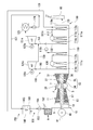
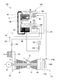
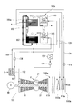
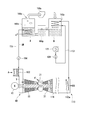
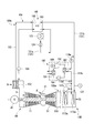
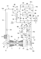
- 1 is an overall system diagram of a gas turbine plant in a first embodiment according to the present invention. It is a principal part system diagram of the gas turbine plant in 1st embodiment which concerns on this invention. It is a principal part system diagram of the gas turbine plant in the 1st modification of 1st embodiment which concerns on this invention. It is a principal part system diagram of the gas turbine plant in the 2nd modification of 1st embodiment which concerns on this invention. It is a principal part system diagram of the gas turbine plant in the 3rd modification of 1st embodiment which concerns on this invention. It is a principal part system diagram of the gas turbine plant in 2nd embodiment which concerns on this invention. It is a principal part system diagram of the gas turbine plant in 3rd embodiment which concerns on this invention.
- the gas turbine plant of the present embodiment includes a gas turbine 10, a generator 41 that generates electric power by driving the gas turbine 10, and an exhaust gas that recovers heat of exhaust gas EG exhausted from the gas turbine 10.
- a heat recovery facility 100 and a chimney 60 that discharges the exhaust gas EG that has passed through the exhaust heat recovery facility 100 to the atmosphere are provided.
- the gas turbine 10 includes a compressor 11 that compresses air A, an intake duct 9 that guides air to the compressor 11, and a combustion that generates combustion gas by burning fuel F in the air A compressed by the compressor 11. And a turbine 31 driven by high-temperature and high-pressure combustion gas.
- the compressor 11 includes a compressor rotor 13 that rotates about an axis Ar, and a compressor casing 17 that rotatably covers the compressor rotor 13.
- the direction in which the axis line Ar extends is the axial direction.
- one axial side is the upstream side in the axial direction, and the other axial side is the downstream side in the axial direction.
- the axial upstream side of the compressor casing 17 is open. This opening forms a suction port 19 for sucking air.
- the intake duct 9 is installed on the upstream side in the axial direction of the compressor 11. The intake duct 9 is connected to a suction port 19 of the compressor casing 17.
- the turbine 31 is installed on the downstream side in the axial direction of the compressor 11.
- the turbine 31 includes a turbine rotor 33 that rotates about the axis Ar by the combustion gas from the combustor 21, and a turbine casing 37 that covers the turbine rotor 33 rotatably.
- the turbine rotor 33 includes a rotor shaft 34 extending in the axial direction and a plurality of blades 35 fixed to the outer periphery of the rotor shaft 34.
- a plurality of stationary blades 38 are fixed to the inner peripheral surface of the turbine casing 37.
- a combustion gas flow path through which the combustion gas from the combustor 21 passes is formed between the inner peripheral surface of the turbine casing 37 and the outer peripheral surface of the rotor shaft 34.
- the turbine rotor 33 and the compressor rotor 13 are connected to each other and rotate integrally around the same axis Ar.
- the turbine rotor 33 and the compressor rotor 13 constitute the gas turbine rotor 3.
- the gas turbine rotor 3 is connected to the rotor of the generator 41 described above.
- the turbine casing 37 and the compressor casing 17 are connected to each other to form the gas turbine casing 7.
- the combustor 21 is fixed to the gas turbine casing 7.
- the exhaust heat recovery facility 100 includes an exhaust heat recovery boiler 110, steam turbines 121a and 121c, generators 122a and 122c, a condenser 123, a feed water pump 124, and an intake air cooling device 150.
- the exhaust heat recovery boiler 110 generates steam by the heat of the combustion gas driving the turbine 31, that is, the exhaust gas EG exhausted from the gas turbine 10.
- the steam turbines 121a and 121c are driven by steam generated in the exhaust heat recovery boiler 110.
- the generators 122a and 122c generate power by driving the steam turbines 121a and 121c.
- the condenser 123 returns the steam that has driven the steam turbine 121a to water.
- the water supply pump 124 returns the water in the condenser 123 to the exhaust heat recovery boiler 110.
- the intake air cooling device 150 cools the air A sucked by the compressor 11.
- the exhaust heat recovery facility 100 includes a low-pressure steam turbine 121a and a high-pressure steam turbine 121c as the steam turbines 121a and 121c.
- Generators 122a and 122c are connected to the low-pressure steam turbine 121a and the high-pressure steam turbine 121c, respectively.
- the generators 122a and 122c are connected to the steam turbines 121a and 121c, respectively, but the rotors of the low-pressure steam turbine 121a and the high-pressure steam turbine 121c are connected to each other, and for a total of two steam turbines, One generator may be connected.
- the exhaust heat recovery boiler 110 has a boiler outer frame 119, a low-pressure steam generator 111a that generates low-pressure steam LS, and a high-pressure steam generator 111c that generates high-pressure steam HS. At least a part of each of the low-pressure steam generator 111 a and the high-pressure steam generator 111 c is set in the boiler outer frame 119.
- the boiler outer frame 119 is connected to the exhaust port of the turbine casing 37 and the chimney 60. For this reason, the combustion gas obtained by rotating the turbine rotor 33 flows from the gas turbine 10 into the boiler outer frame 119 as the exhaust gas EG.
- the exhaust gas EG passes through the boiler outer frame 119, and is discharged from the exhaust port 119e of the boiler outer frame 119 through the chimney 60 to the atmosphere.
- the exhaust port side of the boiler outer frame 119 is the downstream side of the flow of the exhaust gas EG, and the opposite side is the upstream side.
- the low-pressure steam generation part 111a is disposed downstream of the high-pressure steam generation part 111c.
- the low-pressure steam generator 111a includes a low-pressure economizer 112a that heats water, a low-pressure evaporator (most downstream evaporator) 113a that vaporizes water heated by the low-pressure economizer 112a, and a low-pressure evaporator 113a.
- a low-pressure superheater 114a that superheats the generated steam to generate low-pressure steam LS.
- the low pressure superheater 114a and the low pressure economizer 112a are both installed in the boiler outer frame 119.
- the evaporation drum which is a part of the low-pressure evaporator 113a is installed outside the boiler outer frame 119.
- the heat transfer tube which is another part of the low-pressure evaporator 113a, is installed in the boiler outer frame 119.
- the elements constituting the low-pressure steam generator 111a are arranged in the order of the low-pressure superheater 114a, the low-pressure evaporator 113a, and the low-pressure economizer 112a toward the downstream side.
- the high-pressure steam generator 111c includes a high-pressure pump 116c that pressurizes water heated by the low-pressure economizer 112a, a high-pressure economizer 112c that heats water pressurized by the high-pressure pump 116c, and a high-pressure economizer 112c. It has a high-pressure evaporator 113c that turns heated water into steam, and a high-pressure superheater 114c that superheats the steam generated in the high-pressure evaporator 113c to generate high-pressure steam HS.
- the high pressure superheater 114c and the high pressure economizer 112c are both installed in the boiler outer frame 119.
- the evaporation drum which is a part of the high-pressure evaporator 113c is installed outside the boiler outer frame 119.
- the heat transfer tube which is another part of the high-pressure evaporator 113c, is installed in the boiler outer frame 119.
- the high-pressure pump 116c is installed outside the boiler outer frame 119.
- the elements constituting the high-pressure steam generator 111c are arranged in the order of the high-pressure superheater 114c, the high-pressure evaporator 113c, and the high-pressure economizer 112c toward the downstream side.
- the low-pressure economizer 112a is connected to a low-pressure water line 117 that guides the water heated here to the low-pressure evaporator 113a.
- the low-pressure water line 117 is branched on the way. This branched line is connected to the high-pressure economizer 112c as a low-pressure water branch line 117c.
- the low-pressure water branch line 117c is provided with a high-pressure pump 116c.
- the condenser 123 and the low pressure economizer 112 a of the exhaust heat recovery boiler 110 are connected by a water supply line 131.
- the water supply line 131 is provided with the above-described water supply pump 124.
- the low pressure superheater 114a and the steam inlet of the low pressure steam turbine 121a are connected by a low pressure steam line 132 that sends the low pressure steam LS from the low pressure superheater 114a to the low pressure steam turbine 121a.
- the steam outlet of the low-pressure steam turbine 121 a and the condenser 123 are connected to each other so that the low-pressure steam LS that drives the low-pressure steam turbine 121 a is supplied to the condenser 123.
- the high pressure superheater 114c and the steam inlet of the high pressure steam turbine 121c are connected by a high pressure steam line 138 that sends the high pressure steam HS from the high pressure superheater 114c to the high pressure steam turbine 121c.
- a high pressure steam recovery line 139 is connected to the steam outlet of the high pressure steam turbine 121c.
- the high pressure steam recovery line 139 merges with the low pressure steam line 132.
- the intake air cooling device 150 includes the above-described water supply line 131 and a heat pump device 151.
- the heat pump device 151 moves the heat of the air A sucked by the compressor 11 to the water flowing through the water supply line 131 to cool the air A while heating the water.
- the heat pump device 151 includes a refrigerator 160 that is a kind of heat pump, an intake air cooler 152 that cools air sucked by the compressor 11 with an intake air cooling medium SM cooled by the refrigerator 160, an intake air cooler 152, and a refrigerator 160. Are connected to each other, and a circulation pump 154 that circulates the intake cooling medium SM in the intake cooling medium line 153.
- the refrigerator 160 of the present embodiment is an absorption refrigerator.
- the refrigerator 160 of this embodiment includes a regenerator 161 that evaporates the medium M from the absorbing liquid A containing the medium M, a condenser 163 that condenses the gaseous medium M from the regenerator 161, and a liquid from the condenser 163.
- the absorbing liquid A containing the medium M is heated by heat from the outside, and the medium M is evaporated from the absorbing liquid A. As a result, the amount of the medium M in the absorbing liquid A is reduced. That is, the absorbing liquid A that has been diluted with the medium M is regenerated into a thick absorbing liquid A by the regenerator 161.
- heat from a heat source medium such as high-temperature water or high-temperature steam supplied from the outside, or the like is used.
- a water supply line 131 is connected to the condenser 163.
- heat exchange is performed between the gaseous medium M from the regenerator 161 and the water from the water supply line 131 to cool and condense the medium M, while heating the water from the water supply line 131.
- the water heated by the condenser 163 passes through the water supply line 131 again and is sent to the low-pressure economizer 112a of the exhaust heat recovery boiler 110.
- the evaporator 165 is connected to an intake cooling medium line 153.
- the liquid medium M from the condenser 163 and the intake cooling medium SM from the intake cooling medium line 153 are heat-exchanged to heat and evaporate the liquid medium M, while the intake cooling medium line
- the intake cooling medium SM from 153 is cooled.
- the intake air cooling medium SM cooled by the evaporator 165 is sent to the intake air cooler 152 through the intake air cooling medium line 153 again.
- a water supply line 131 is connected to the absorber 167.
- the absorbent A regenerated by the regenerator 161 flows into the absorber 167.
- the gaseous medium M from the evaporator 165 also flows into the absorber 167.
- the absorber 167 the gaseous medium M is absorbed by the regenerated absorbing liquid A.
- the pressure in the evaporator 165 decreases, and the evaporation of the liquid medium M in the evaporator 165 is promoted.
- the absorber 167 the absorbing liquid A is diluted with the medium M.
- the diluted absorption liquid A is sent to the regenerator 161 and regenerated as described above.
- the absorber 167 when the absorbing liquid A is diluted by the medium M, dilution heat is generated. This heat of dilution is recovered in the water in the water supply line 131 passing through the absorber 167.
- the intake air cooler 152 is provided in the intake duct 9 of the gas turbine 10.
- the intake air cooler 152 heat-exchanges the air A passing through the intake duct 9 and the intake air cooling medium SM in the intake air cooler 152 to cool the air A passing through the intake duct 9 while heating the intake air cooling medium SM. .
- the heated intake cooling medium SM is sent to the evaporator 165 via the intake cooling medium line 153.
- Examples of the absorbent A used in the absorption refrigerator 160 of the present embodiment include lithium bromide and ammonia.
- the medium M used in the absorption refrigerator 160 includes water.
- examples of the intake cooling medium SM include water. These absorbing liquid A, medium M, and intake air cooling medium SM are not limited to the above, and can be appropriately changed depending on temperature conditions and the like.
- the compressor 11 of the gas turbine 10 compresses the air A and supplies the compressed air A to the combustor 21.
- fuel F is also supplied to the combustor 21.
- the fuel F is combusted in the compressed air A, and high-temperature and high-pressure combustion gas is generated.
- This combustion gas is sent from the combustor 21 to the combustion gas passage in the turbine 31 to rotate the turbine rotor 33.
- the generator 41 connected to the gas turbine 10 generates power by the rotation of the turbine rotor 33.
- the combustion gas that has rotated the turbine rotor 33 is exhausted from the gas turbine 10 as exhaust gas EG, and is discharged from the chimney 60 to the atmosphere via the exhaust heat recovery boiler 110.
- the exhaust heat recovery boiler 110 recovers heat contained in the exhaust gas EG in a process in which the exhaust gas EG from the gas turbine 10 passes through the exhaust heat recovery boiler 110.
- the exhaust heat recovery boiler 110 water is supplied from the water supply line 131 to the most downstream low-pressure heat exchanger 115a (water supply process).
- the low pressure economizer 112a heat exchange is performed between the exhaust gas EG and the water flowing therein, and the exhaust gas EG is cooled while heating water.
- a part of the water heated by the low pressure economizer 112a is further heated by the low pressure evaporator 113a to become steam.
- This steam is further heated by the low-pressure superheater 114a and supplied as low-pressure steam LS to the low-pressure steam turbine 121a via the low-pressure steam line 132.
- the steam that has driven the low-pressure steam turbine 121 a returns to water in the condenser 123.
- the water in the condenser 123 is boosted by the feed water pump 124, returns to the low pressure economizer 112 a of the exhaust heat recovery boiler 110 through the feed water line 131 and the refrigerator 160.
- the other part of the water heated by the low pressure economizer 112a is pressurized by the high pressure pump 116c.
- the water pressurized by the high-pressure pump 116c is sent to the high-pressure economizer 112c via the low-pressure water branch line 117c.
- the high pressure economizer 112c heats the water sent from the high pressure pump 116c by exchanging heat with the exhaust gas EG.
- the water heated by the high pressure economizer 112c is further heated by the high pressure evaporator 113c to become steam.
- This steam is further heated by the high-pressure superheater 114c to become high-pressure steam HS.
- the high-pressure steam HS is supplied to the high-pressure steam turbine 121c via the high-pressure steam line 138, and drives the high-pressure steam turbine 121c.
- the steam that has driven the high-pressure steam turbine 121c is supplied to the low-pressure steam turbine 121a via the high-pressure steam recovery line 139 and the low-pressure steam line 132, and drives the low-pressure steam turbine 121a.
- the steam that has driven the low-pressure steam turbine 121a returns to water in the condenser 123 as described above.
- the gas turbine 10 As the mass flow rate of the gas flowing through the combustion gas flow path of the turbine 31 increases, the gas turbine output improves.
- the intake air cooler 152 is provided in the intake duct 9, and the air A sucked by the compressor 11 is cooled by the intake air cooler 152.
- the temperature of the air A flowing into the intake duct 9 is 30 to 35 ° C., for example, the temperature of the air A is lowered to about 12 to 17 ° C. by the intake air cooler 152.
- the intake air cooler 152 heat exchange is performed between the air A passing through the intake duct 9 and the intake air cooling medium SM in the intake air cooler 152 to cool the air A passing through the intake duct 9, while heating the intake air cooling medium SM.
- the heated intake cooling medium SM is sent to the evaporator 165 of the refrigerator 160 through the intake cooling medium line 153.
- the gas medium M from the regenerator 161 and the water from the water supply line 131 are heat-exchanged to cool and condense the medium M, while the water supply line Heat water from 131.
- the water heated by the condenser 163 passes through the water supply line 131 again and is sent to the low-pressure economizer 112a of the exhaust heat recovery boiler 110. Therefore, the water sent to the exhaust heat recovery boiler 110 is preheated by the condenser 163.
- the temperature of the water from the condenser 123 is 30 to 35 ° C., for example, the temperature of the water is increased to about 36 to 40 ° C. by the condenser 163.
- the medium M that has been deprived of heat and condensed by heat exchange with water from the water supply line 131 flows into the evaporator 165 of the refrigerator 160.
- the liquid medium M from the condenser 163 and the intake cooling medium SM from the intake cooling medium line 153 are heat-exchanged to heat and evaporate the liquid medium M.
- the intake cooling medium SM from the intake cooling medium line 153 is cooled.
- the intake air cooling medium SM cooled by the evaporator 165 is sent to the intake air cooler 152 through the intake air cooling medium line 153 again.
- the medium M that has absorbed heat and evaporated by heat exchange with the intake cooling medium SM flows into the absorber 167 of the refrigerator 160 and is absorbed by the absorbing liquid A.
- the dilution heat generated when the absorbing liquid A is absorbed by the medium M is recovered by the water in the water supply line 131 passing through the absorber 167.
- the evaporator 165 moves the heat of the intake cooling medium SM to the medium M to cool the intake cooling medium SM, and the condenser 163 converts the heat of the medium M to the water from the water supply line 131.
- the water is heated to heat (heat pump cycle execution step). That is, in this embodiment, heat transfer is performed between the water from the water supply line 131 and the intake air cooling medium SM via the medium M. For this reason, in this embodiment, heat transfer is performed between the water from the water supply line 131 and the air A passing through the intake duct 9 via the medium M of the refrigerator 160 and the intake cooling medium SM.
- the air sent to the exhaust heat recovery boiler 110 can be preheated using the heat obtained by cooling the air A while cooling the air A sucked by the gas turbine 10.
- the regenerator 161 of the absorption refrigerator 160 in the first embodiment heat obtained by burning the fuel of the gas turbine 10, heat from a heat source medium such as high-temperature water and high-temperature steam supplied from the outside, and the like are used.
- the absorbent A used is heated.
- the absorbing liquid A is heated using the exhaust heat from the gas turbine 10.
- the exhaust heat recovery boiler 110a in the exhaust heat recovery facility 100a of this modification is a low temperature heat exchanger (exhaust heat recovery heat exchanger) 115a disposed in the boiler outer frame 119 and downstream of the low pressure economizer 112a.
- This low-temperature heat exchanger 115a exchanges heat between the exhaust gas EG that has passed through the low-pressure economizer 112a and the absorbent heating medium.
- the regenerator 161a in the absorption refrigerator 160a of the present modification includes an absorption liquid heater 162 that exchanges heat between the absorption liquid heating medium and the absorption liquid A.
- the absorption liquid heater 162 and the low temperature heat exchanger 115a are connected by an absorption liquid heating medium line 171.
- the absorption liquid heating medium line 171 is provided with a pump 172 for circulating the absorption liquid heating medium in the line 171.
- the absorbing liquid heating medium is heated by the heat exchange between the exhaust gas EG and the absorbing liquid heating medium in the low-temperature heat exchanger 115a (exhaust heat recovery step).
- the absorption liquid heating medium is sent to the absorption liquid heater 162 of the regenerator 161a via the absorption liquid heating medium line 171.
- the absorption liquid A in the regenerator 161a and the absorption liquid heating medium are heat-exchanged to heat the absorption liquid A in the regenerator 161a while cooling the absorption liquid heating medium.
- the medium M contained in the absorption liquid A evaporates.
- the absorbing liquid A diluted with the medium M is regenerated to a thick absorbing liquid A by the regenerator 161a (regenerating step).
- the cooled absorption liquid heating medium is sent to the low-temperature heat exchanger 115a via the absorption liquid heating medium line 171. In the low-temperature heat exchanger 115a, as described above, the absorption liquid heating medium is heated.
- the absorbing liquid A in the regenerator 161a is heated by the heat of the exhaust gas EG that has passed through the low-pressure economizer 112a. Therefore, in this modification, consumption of the fuel and the heat source medium when heating the absorbing liquid A in the regenerator 161a can be suppressed.
- the absorption liquid A when the absorption liquid A is not sufficiently heated by the absorption liquid heater 162, it may be supplementarily heated by a fuel or a heat source medium.
- the absorption liquid A in the regenerator 161a in the absorption refrigerator 160 is heated using the exhaust heat from the gas turbine 10.
- the gas turbine plant of this modification includes a component cooling device 175 that cools high-temperature components that are in contact with the combustion gas in the gas turbine 10 with the air extracted from the compressor 11 of the gas turbine 10.
- the component cooling device 175 includes a compressed air cooler 176 that exchanges heat between the air A extracted from the compressor 11 of the gas turbine 10 and the absorption liquid heating medium, and the compressed air cooler 176 that extracts the air A extracted from the compressor 11. It has a bleed line 177 for guiding it, and a cooling air line 178 for guiding the air A cooled by the compressed air cooler 176 to the high temperature components of the gas turbine 10.
- the regenerator 161a of the present modification also has an absorption liquid heater 162 for exchanging heat between the absorption liquid heating medium and the absorption liquid A, similarly to the regenerator 161a of the first modification.
- the absorption liquid heater 162 and the compressed air cooler 176 are connected by an absorption liquid heating medium line 171a.
- the absorption liquid heating medium line 171a is provided with a pump 172a for boosting the absorption liquid heating medium.
- the exhaust heat recovery facility 100b of this modification includes the component cooling device 175 described above.
- the air A extracted from the compressor 11 and the absorption liquid heating medium are heat-exchanged by the compressed air cooler 176.
- the absorption liquid heating medium is heated (exhaust heat recovery step).
- the cooled air is sent to the hot components of the gas turbine 10 via the cooling air line 178.
- the high temperature component include a stationary blade 38 and a moving blade 35 of the turbine 31.
- the absorbing liquid heating medium heated by the compressed air cooler 176 is sent to the absorbing liquid heater 162 of the regenerator 161a through the absorbing liquid heating medium line 171a.
- the absorption liquid heating medium is cooled (regeneration step).
- the cooled absorption liquid heating medium is sent to the compressed air cooler 176 via the absorption liquid heating medium line 171a.
- the absorption liquid heating medium is heated as described above.
- the absorption liquid A in the regenerator 161a is heated by the heat of the air extracted from the compressor 11. Therefore, even in this modification, it is possible to suppress the consumption of the fuel and the heat source medium when the absorbing liquid A in the regenerator 161a is heated. Also in this modification, when the absorption liquid A is not sufficiently heated by the absorption liquid heater 162, heat obtained by auxiliary combustion of fuel or gas turbine fuel, or supply from the outside Heating with a heat source medium such as high-temperature water or high-temperature steam may be performed.
- the refrigerator of the above embodiment is an absorption refrigerator 160.
- the refrigerator is not limited to the absorption refrigerator 160, and may be, for example, a compression refrigerator.
- the compression refrigerator 160p includes an evaporator 165p that evaporates the medium M, a compressor 168p that compresses the medium M vaporized by the evaporator 165, and a compressor 168p.
- a compressor using a centrifugal compressor as the compressor 168p may be referred to as a turbo refrigerator.
- any type of compressor such as a reciprocating compressor or a rotary compressor may be used as the compressor 168p in addition to a centrifugal compressor.
- the intake cooling medium line 153 is connected to the evaporator 165p of the compression refrigerator 160p.
- heat exchange is performed between the liquid medium M and the intake cooling medium SM from the intake cooling medium line 153 to heat and evaporate the liquid medium M, while intake air from the intake cooling medium line 153 is obtained.
- the cooling medium SM is cooled.
- the intake air cooling medium SM cooled by the evaporator 165 is sent to the intake air cooler 152 through the intake air cooling medium line 153 again.
- the gaseous medium M is compressed by the compressor 168p and then sent to the condenser 163p.
- a water supply line 131 is connected to the condenser 163p.
- the gaseous medium M compressed by the compressor 168p and the water from the water supply line 131 are heat-exchanged to cool and condense the gaseous medium M, while water from the water supply line 131 is condensed. Heat.
- the water heated by the condenser 163p is sent again to the low-pressure economizer 112a of the exhaust heat recovery boiler 110 through the water supply line 131.
- the medium M condensed by the condenser 163p is decompressed.
- the decompressed liquid medium M flows into the evaporator 165, where it is heat-exchanged with the intake air cooling medium SM from the intake air cooling medium line 153 as described above.
- the refrigerator of the above-described embodiment may not be the absorption refrigerator 160, but may be the compression refrigerator 160p as in the present modification, and still another type of refrigerator, such as an adsorption refrigerator, etc. It may be.
- the heat pump device is different from that of the first embodiment, and other configurations are the same as those of the first embodiment.
- the heat pump device 151c of this embodiment includes a refrigerator 160 that is a kind of heat pump, an intermediate heat exchanger 155c, an intermediate medium line 156c, a circulation pump 157c, an intake air cooler 152, an intake air cooling medium line 153c, A circulation pump 154c.
- the intermediate heat exchanger 155c exchanges heat between the intermediate medium cooled by the refrigerator 160 and the intake cooling medium SM.
- the intermediate medium line 156c connects the evaporator 165 and the intermediate heat exchanger 155c of the refrigerator 160.
- the circulation pump 157c circulates the intermediate medium in the intermediate medium line 156c.
- the intake air cooler 152 cools the air A sucked by the compressor 11 with an intermediate medium.
- the intake air cooling medium line 153c connects the intake air cooler 152 and the intermediate heat exchanger 155c.
- the circulation pump 154c circulates the intake cooling medium SM in the intake cooling medium line 153c.
- the intake air cooler 152 provided in the intake duct 9 exchanges heat between the air A sucked by the compressor 11 and the intake air cooling medium SM, and the air A is cooled while the intake air cooling medium SM. Is heated.
- the heated intake cooling medium SM is heat-exchanged with the intermediate medium by the intermediate heat exchanger 155c and cooled.
- the intake air cooling medium SM cooled by the intermediate heat exchanger 155c is sent to the intake air cooler 152.
- the intermediate medium heated by heat exchange with the intake air cooling medium SM is sent to the evaporator 165 of the refrigerator 160 and cooled by the evaporator 165.
- the intermediate medium cooled by the evaporator 165 of the refrigerator 160 returns to the intermediate heat exchanger 155c where the intake air cooling medium SM is cooled.
- the air A sucked by the compressor 11 is directly cooled by the intake air cooling medium SM cooled by the refrigerator 160.
- the intake air cooling medium SM may be cooled via the intermediate medium cooled by the refrigerator 160, and the air A sucked by the compressor 11 may be cooled by the intake air cooling medium SM.
- the intake air cooling device is different from that of the first embodiment, and other configurations are the same as those of the first embodiment.
- the intake air cooling device 150d of this embodiment includes a water supply line 131 and a heat pump device 151, as in the first embodiment.
- the heat pump device 151 is the same as the heat pump device 151 of the first embodiment.
- the intake air cooling device 150d of the present embodiment further includes a feed water temperature regulator 181 that takes heat from the water flowing through the feed water line 131.
- the water supply temperature controller 181 may be anything as long as it takes heat from the water flowing through the water supply line 131 and lowers the temperature of the water. Therefore, the feed water temperature controller 181 may be, for example, a heat exchanger that exchanges heat between water and a water cooling medium, a cooling tower, or a radiator that releases heat of water to the atmosphere.
- a heat exchanger is used as the feed water temperature controller 181
- river water, sea water, ground water, or the like may be used as the water cooling medium.
- a fuel supplied to the combustor may be used as a water cooling medium, and the fuel may be preheated by heat exchange between water and fuel.
- the water supply line 131 includes a preheated water supply line 131 a that sends water from the condenser 123 to the refrigerator 160 of the heat pump device 151, and a preheated water supply line 131 b that sends water preheated by the refrigerator 160 to the exhaust heat recovery boiler 110. And having.
- the preheated water supply line 131a and the preheated water supply line 131b are connected by a water supply bypass line 131c.
- the feed water pump 124 is provided in the pre-preheating feed water line 131a and closer to the condenser 123 than the connection position with the feed water bypass line 131c.
- a pre-heating water supply adjustment valve 182 is provided on the refrigerator 160 side of the connection position with the water supply bypass line 131c. Further, in the preheated water supply line 131b, a preheated water supply adjustment valve 183 is provided closer to the refrigerator 160 than the connection position with the water supply bypass line 131c. In the preheated water supply line 131b, the exhaust heat recovery boiler 110 side is provided with a thermometer 127 that detects the temperature of the water flowing therethrough. A water supply bypass adjusting valve 184 is provided in the water supply bypass line 131c.
- the position on the refrigerator 160 side of the preheated water supply control valve 183 in the preheated water supply line 131b and the position on the refrigerator 160 side of the preheated water supply control valve 182 in the preheated water supply line 131a are the water supply temperature control line. 185 is connected.
- the feed water temperature regulator 181 is provided in the feed water temperature regulation line 185.
- a temperature adjustment valve 186 and a return pump 187 are provided in the feed water temperature adjustment line 185.
- the water sent to the low pressure economizer 112a can be preheated by heating the water from the condenser 123 with the refrigerator 160.
- the low-pressure economizer 112a boils before water flows into the low-pressure evaporator 113a by heat exchange between the preheated water and the exhaust gas EG. It is possible to start. If water begins to boil before flowing into the low-pressure evaporator 113a, problems such as an increase in pressure loss and the occurrence of a water hammer phenomenon occur.
- a feed water temperature controller 181 is provided which takes heat from the water flowing through the preheated water supply line 131b and causes the temperature of this water to rise.
- both the preheated water supply control valve 182 and the preheated water supply control valve 183 are open.
- both the temperature control valve 186 and the water supply bypass control valve 184 are closed.
- the water from the condenser 123 is sent to the refrigerator 160 through the pre-heating water supply line 131 a and heated by the refrigerator 160.
- the water heated by the refrigerator 160 is sent to the low pressure economizer 112a of the exhaust heat recovery boiler 110 via the preheated water supply line 131b.
- the temperature control valve 186 When the temperature detected by the thermometer 127 provided in the preheated water supply line 131b is equal to or higher than a predetermined temperature, the temperature control valve 186 is opened. As a result, a part of the water flowing through the preheated water supply line 131b flows into the water supply temperature regulator 181.
- the predetermined temperature is lower than, for example, a value obtained by subtracting the temperature rise of the water in the low pressure economizer 112a from the saturation temperature at which water boils in the low pressure economizer 112a. Temperature.
- the feed water temperature controller 181 takes heat from this water and lowers the temperature of this water (feed water temperature regulation step).
- the water whose temperature has decreased returns to the refrigerator 160 through the feed water temperature adjustment line 185 and the pre-heating feed water line 131a. Therefore, in the present embodiment, in the system having the refrigerator 160 and the feed water temperature controller 181, the amount of heat applied to the water from the condenser 123 is reduced, and the water sent to the low pressure economizer 112a of the exhaust heat recovery boiler 110 is reduced. The temperature can be lowered. As a result, boiling of water in the low pressure economizer 112a can be suppressed. Moreover, in this embodiment, when a part of water circulates between the refrigerator 160 and the feed water temperature controller 181, the flow rate of the water flowing through the refrigerator 160 is increased, and the temperature rise amount of the water in the refrigerator 160. The temperature of water at the outlet of the refrigerator 160 can be reduced. Therefore, in this embodiment, since the refrigerator 160 can discharge waste heat to low-temperature water, it is possible to use a relatively inexpensive refrigerator 160 and increase the coefficient of performance of the refrigerator 160. be able to.
- the temperature detected by the thermometer 127 provided in the preheated water supply line 131b is determined in advance. There may be cases where the temperature does not fall below the specified temperature.
- the water supply bypass adjustment valve 184 is opened while the preheated water supply adjustment valve 182 or the preheated water supply adjustment valve 183 is throttled. As a result, a part of the water from the condenser 123 flows into the low pressure economizer 112a via the feed water bypass line 131c without passing through the refrigerator 160.
- the pre-heating water supply adjustment valve 182 or the preheated water supply adjustment valve 183 is completely closed while the water supply bypass adjustment valve 184 is opened.
- all of the water from the condenser 123 flows into the low-pressure economizer 112a via the feed water bypass line 131c without passing through the refrigerator 160. Therefore, as described above, by controlling each control valve, the amount of heat applied to the water from the condenser 123 can be further reduced, and the temperature of the water that can be sent to the low-pressure economizer 112a of the exhaust heat recovery boiler 110 Can be lowered.
- the water supply temperature adjustment line 185 for returning the water cooled by the water supply temperature adjuster 181 to the water supply line 131 is condensated in the pre-heating water supply line 131a more than the connection position with the water supply bypass line 131c. You may connect to the device 123 side.
- the intake air cooling device is different from that of the first embodiment, and other configurations are the same as those of the first embodiment.
- the intake air cooling device 150g of this embodiment includes a water supply line 131 and a heat pump device 151, as in the first embodiment.
- the heat pump device 151 is the same as the heat pump device 151 of the first embodiment.
- the intake air cooling device 150g of the present embodiment further includes a condensate return line 179 that returns the preheated water that flows through the preheated water supply line 131b to the condenser 123.
- a thermometer 127 for detecting the temperature of preheated water flowing therethrough is provided on the exhaust heat recovery boiler 110 side.
- a temperature control valve 186 is provided in the condensate return line 179.
- the temperature control valve 186 When the temperature detected by the thermometer 127 provided in the preheated water supply line 131b is equal to or higher than a predetermined temperature, the temperature control valve 186 is opened. As a result, a part of the preheated water flowing through the preheated water supply line 131b returns to the condenser 123 via the condensate return line 179 (condensate return process).
- the predetermined temperature is, for example, from the saturation temperature at which water boils in the low pressure economizer 112a, as described in the third embodiment, and the water in the low pressure economizer 112a. The temperature is lower than the value obtained by subtracting the temperature rise.
- the feed water temperature controller 181 and the like are provided to lower the temperature of the preheated water.
- the condenser 123 has the function of the feed water temperature controller 181.
- the preheated water is returned to the condenser 123, so that the heat of the preheated water is taken away by the condenser 123.
- the temperature rise of the water heated with the heat pump apparatus 151 is suppressed because the flow volume of the water heated with the heat pump apparatus 151 increases. Therefore, also in this embodiment, the temperature of the water sent to the low pressure economizer 112a of the exhaust heat recovery boiler 110 can be lowered as in the third embodiment.
- the gas turbine plant of the present embodiment is obtained by adding a heat pump device 151s to the intake air cooling device 150d in the third embodiment, and other configurations are the same as those in the third embodiment.
- the intake air cooling device 150e in the exhaust heat recovery facility 100e of this embodiment is a water supply line 131, a heat pump device 151 that cools the air A sucked by the compressor 11, and water flowing through the water supply line 131.
- a water supply temperature controller 181 for removing heat from the water is provided.
- the intake air cooling device 150e of the present embodiment further includes a heat pump device 151s that further heats water heated by cooling the air A sucked by the compressor 11.
- the heat pump device 151 that cools the air sucked by the compressor 11 is the first heat pump device 151
- the heat pump device 151 s that further heats the water heated by the first heat pump device 151 is the second heat pump device 151.
- the heat pump device 151s is assumed.
- the second heat pump device 151s includes a water supply circulation line 188 and a refrigerator 160s.
- the returning water supply circulation line 188 branches from the preheated water supply line 131b, and returns a part of the water flowing through the preheated water supply line 131b to the preheated water supply line 131a.
- the refrigerator 160s moves the heat of the water flowing through the water supply circulation line 188 to the water flowing through the preheated water supply line 131b to heat the water.
- the refrigerator 160 of the first heat pump device 151 is the first refrigerator 160
- the refrigerator 160s of the second heat pump device 151s is the second refrigerator 160s.
- the second refrigerator 160s is a kind of heat pump, like the first refrigerator 160, and may be an absorption refrigerator, a compression refrigerator p, an adsorption refrigerator, or the like.
- Each of these refrigerators includes an evaporator that evaporates the liquid medium M and a condenser that condenses the medium M evaporated by the evaporator. Therefore, the second refrigerator 160s of the present embodiment also includes the evaporator 165 and the condenser 163.
- the condenser 163 of the second refrigerator 160s is connected to a portion of the preheated water supply line 131b closer to the exhaust heat recovery boiler 110 than the branch position of the water supply circulation line 188. For this reason, a part of the water heated by the condenser 163 of the first refrigerator 160 is further heated by the condenser 163 of the second refrigerator 160s, and the exhaust heat recovery boiler 110 is passed through the preheated water supply line 131b. Sent to. In the condenser 163 of the second refrigerator 160s, the medium M cooled by heat exchange with water is condensed.
- a water supply circulation line 188 is connected to the evaporator 165 of the second refrigerator 160s. For this reason, the remaining part of the water heated by the condenser 163 of the first refrigerator 160 is cooled by the evaporator 165 of the second refrigerator 160s, and then passes through the water supply circulation line 188 and then the first refrigerator 160. The condenser 163 is returned to. In the evaporator 165 of the second refrigerator 160s, the medium M heated by heat exchange with water evaporates.
- the water flowing through the feed water circulation line 188 is moved to the medium M by the evaporator 165 of the second refrigerator 160s to cool the water, and this second refrigerator is cooled.
- the heat of the medium M is transferred to the water from the preheated water supply line 131b by the 160s condenser 163 to heat the water (second heat pump cycle step). That is, in the second refrigerator 160s, heat transfer is performed between the water from the water supply circulation line 188 and the water from the preheated water supply line 131b via the medium M.
- the water supply circulation line 188 is provided with a water supply circulation amount adjustment valve 189 for adjusting the flow rate of the water flowing therethrough.
- the flow rate of the water flowing through the feed water circulation line 188 is adjusted by the feed water circulation amount adjustment valve 189, so that the flow is performed between the water from the feed water circulation line 188 and the water from the preheated feed water line 131b. Adjust the amount of heat transfer.
- the intake air cooling device 150e of the present embodiment includes the feed water temperature regulator 181 as in the intake air cooling device 150d of the third embodiment, but there is no risk of water boiling in the low pressure economizer 112a.
- the feed water temperature controller 181 may be omitted.
- the intake air cooling device 150e of the present embodiment has a second heat pump device 151s that further heats the water heated by the first heat pump device 151 in addition to the first heat pump device 151 that heats the water from the condenser 123. Therefore, basically, it is preferable to provide this feed water temperature controller 181.
- the gas turbine plant of the present embodiment is obtained by adding a low boiling point medium Rankine cycle 190 to the exhaust heat recovery facility 100 of the first embodiment, and the other configurations are the same as those of the first embodiment.
- Rankine cycle is a cycle that drives a turbine with steam.
- the low boiling point medium Rankine cycle 190 is a cycle in which the turbine 192 is driven using a medium having a lower boiling point than water (hereinafter referred to as a low boiling point medium).
- Examples of the low boiling point medium include the following substances.
- Organic halogen compounds such as trichloroethylene, tetrachloroethylene, monochlorobenzene, dichlorobenzene and perfluorodecalin
- Alkanes such as butane, propane, pentane, hexane, heptane, octane and decane
- Cyclic alkanes such as cyclopentane and cyclohexane
- Aromatic compounds ⁇ Refrigerants such as R134a and R245fa, ⁇ A combination of the above
- the low boiling point medium Rankine cycle 190 includes an evaporator (heater) 191, a turbine 192, a condenser 193, a low boiling point medium pump 194, and a low boiling point medium line 197.
- the evaporator 191 heats and evaporates the liquid low boiling point medium.
- the turbine 192 is driven by the evaporated low boiling point medium.
- the condenser 193 cools and condenses the low boiling point medium that has driven the turbine 192.
- the low boiling point medium pump 194 returns the condensed low boiling point medium to the evaporator 191.
- the low boiling point medium line 197 is a line for flowing the low boiling point medium between the above elements.
- a generator 199 that generates electric power by driving the turbine 192 is connected to the turbine 192.
- the condenser 193 is a kind of heat exchanger, and exchanges heat between a low boiling point medium and a cooling medium such as water.
- the evaporator (heater) 191 is also a kind of heat exchanger, and exchanges heat between the liquid low boiling point medium and the liquid water heated by the exhaust heat recovery boiler 110.
- the low-pressure water branch line 117c of the exhaust heat recovery boiler 110 is branched halfway. This branched line is connected to the preheated water supply line 131b as a hot water line 118c.
- the hot water line 118 c is connected to the evaporator 191 of the low boiling point medium Rankine cycle 190. Specifically, the heating water inlet of the evaporator 191 is connected to the low pressure economizer 112a side of the hot water line 118c, and the heating water outlet of the evaporator 191 is connected to the preheated water supply line 131b side of the hot water line 118c. .
- the hot water line 118c is provided with a hot water flow rate adjusting valve 118d for adjusting the flow rate of water flowing therethrough and a hot water pump 118e for increasing the pressure of water flowing through the hot water line 118c. Further, in the preheated water supply line 131b, a thermometer 127 for detecting the temperature of the water flowing therethrough is provided at a position closer to the exhaust heat recovery boiler 110 than the connection position with the hot water line 118c.
- the hot water flow rate adjustment valve 118d is in a closed state in the initial state. For this reason, in this initial state, the low boiling point medium Rankine cycle and the hot water pump 118e are not driven.
- the water from the condenser 123 is sent to the refrigerator 160 through the pre-heating water supply line 131 a and heated by the refrigerator 160.
- the water heated by the refrigerator 160 is sent to the low pressure economizer 112a of the exhaust heat recovery boiler 110 via the preheated water supply line 131b.
- thermometer 127 provided in the preheated water supply line 131b is equal to or higher than a predetermined temperature
- the hot water flow rate control valve 118d is opened and the low boiling point medium Rankine cycle and the hot water pump 118e start to be driven.
- the evaporator 191 exchanges heat between the liquid low boiling point medium and the water heated by the low pressure economizer 112a, heats the low boiling point medium, and evaporates the low boiling point medium (heating step).
- the water is cooled and flows out from the heating water outlet of the evaporator 191.
- the water flowing out from the heating water outlet of the evaporator 191 flows into the preheated water supply line 131b through the hot water line 118c. This water is mixed with the water from the refrigerator 160, flows through the preheated water supply line 131b, and returns to the low-pressure economizer 112a (water recovery step).
- the low boiling point medium evaporated in the evaporator 191 drives the turbine 192 that is a component of the low boiling point Rankine cycle 190.
- the low boiling point medium that has driven the turbine 192 is sent to the condenser 193.
- the condenser 193 the low boiling point medium and the cooling medium are heat-exchanged, and the low boiling point medium is cooled and condensed.
- the condensed low boiling point medium is sent to the evaporator 191 by the low boiling point medium pump 194, and exchanges heat with water in the evaporator 191 as described above.
- the low boiling point medium circulates in the low boiling point medium Rankine cycle 190 (Rankine cycle execution step).
- the amount of heat applied to the water from the refrigerator 160 is reduced, and the low pressure economizer of the exhaust heat recovery boiler 110 is reduced.
- the temperature of the water that can be sent to 112a can be lowered.
- boiling of water in the low pressure economizer 112a can be suppressed.
- extra heat can be utilized for the drive of the low boiling-point medium Rankine cycle 190 among the heat contained in the water heated with the refrigerator 160, and the output and efficiency of a plant can be improved.
- the gas turbine plant of the present embodiment is obtained by adding the low boiling point Rankine cycle 190 described in the sixth embodiment to the exhaust heat recovery facility 100e of the fifth embodiment, and the other configuration is the fifth embodiment. It is the same as the form.
- the low-pressure water branch line 117c of the exhaust heat recovery boiler 110 branches in the middle as in the sixth embodiment.
- This branched line is connected to the preheated water supply line 131b as a hot water line 118c.
- the hot water line 118c is connected to the evaporator 191 of the low boiling point medium Rankine cycle 190.
- the hot water line 118c is provided with a hot water flow rate adjusting valve 118d for adjusting the flow rate of water flowing therethrough and a hot water pump 118e for increasing the pressure of water flowing through the hot water line 118c.
- a thermometer 127 for detecting the temperature of the water flowing therethrough is provided at a position closer to the exhaust heat recovery boiler 110 than the connection position with the hot water line 118c.
- both the preheated water supply control valve 182 and the preheated water supply control valve 183 are open.
- both the temperature control valve 186 and the water supply bypass control valve 184 are closed.
- the hot water flow rate adjustment valve 118d is in a closed state, as in the sixth embodiment. For this reason, in this initial state, the low boiling point medium Rankine cycle 190 and the hot water pump 118e are not driven.
- the water from the condenser 123 is sent to the first refrigerator 160 through the pre-heating water supply line 131 a and heated by the first refrigerator 160.
- the water heated by the first refrigerator 160 is sent to the second refrigerator 160s via the preheated water supply line 131b and further heated by the second refrigerator 160s.
- the water heated by the second refrigerator 160s is sent to the low pressure economizer 112a of the exhaust heat recovery boiler 110 via the preheated water supply line 131b.
- thermometer 127 provided in the preheated water supply line 131b reaches a predetermined temperature or higher
- the hot water flow rate adjustment valve 118d opens and the low boiling point medium Rankine cycle 190 and the hot water pump 118e start to drive.
- the liquid low boiling point medium and the water heated by the low pressure economizer 112a are subjected to heat exchange, the low boiling point medium is heated, and the low boiling point medium is evaporated (heating). Process).
- the water is cooled and then flows into the preheated water supply line 131b through the hot water line 118c. This water is mixed with the water from the second refrigerator 160s, flows through the preheated water supply line 131b, and returns to the low-pressure economizer 112a (water recovery step).
- the low boiling point medium that has driven the turbine 192 is sent to the condenser 193 where it is condensed.
- the condensed low boiling point medium is sent to the evaporator 191 by the low boiling point medium pump 194, and exchanges heat with water in the evaporator 191 as described above.
- the low boiling point medium circulates in the low boiling point medium Rankine cycle 190 (Rankine cycle execution step).
- the amount of heat applied to the water from the second refrigerator 160s is reduced, and The temperature of the water which can be sent to the low pressure economizer 112a of the heat recovery boiler 110 can be lowered. As a result, water evaporation in the low pressure economizer 112a can be suppressed. Also in this embodiment, excess heat out of the heat contained in the water heated by the first refrigerator 160 and the second refrigerator 160s can be used for driving the low boiling point Rankine cycle 190, and the plant output and Efficiency can be increased.
- thermometer 127 provided in the preheated water supply line 131b is less than a predetermined temperature. There are cases where this is not possible.
- the temperature control valve 186 is opened, and a part of the water flowing through the preheated water supply line 131b flows into the water supply temperature controller 181.
- the feed water temperature controller 181 takes heat from the water and lowers the temperature of the water. The water whose temperature has decreased returns to the first refrigerator 160 via the feed water temperature adjustment line 185 and the pre-heating feed water line 131a.
- the amount of heat applied to the water from the condenser 123 is reduced in the system having the first refrigerator 160, the second refrigerator 160s, and the feed water temperature controller 181, and the low pressure of the exhaust heat recovery boiler 110 is reduced.
- the temperature of the water sent to the economizer 112a can be lowered.
- the water supply temperature adjustment line 185 for returning the water cooled by the water supply temperature adjuster 181 to the water supply line 131 is provided in the preheated water supply line 131a. You may connect to the condenser 123 side rather than the connection position with the bypass line 131c.
- the feed water temperature controller 181 may be omitted. Also in the present embodiment, the condensate return line 179 and the temperature control valve 186 in the fourth embodiment may be provided instead of the feed water temperature controller 181.
- the low-boiling-point medium Rankine cycle 190 described in the present embodiment and the fifth embodiment is an example of a basic aspect of the low-boiling-point medium Rankine cycle. You may employ
- the low boiling point medium Rankine cycle 190 in the above embodiment causes the low boiling point medium condensed in the condenser 193 to exchange heat with the low boiling point medium that has driven the turbine 192, so that the condensed low boiling point medium is heated.
- a vessel may be added.
- a plurality of evaporators 191 may be connected in series or in parallel to the condenser 193, and a turbine 192 may be provided for each of the plurality of evaporators 191.
- the refrigerator 160 in the second embodiment, the third embodiment and the fifth embodiment, and the first refrigerator 160 in the fourth embodiment and the sixth embodiment are all the same as the refrigerator 160 in the first embodiment.
- the refrigerator 160 in these embodiments may also be other types of refrigerators such as a compression refrigerator 160p and an adsorption refrigerator.
- the regenerator 161 of the absorption refrigerator heats the absorption liquid A using the exhaust heat from the gas turbine 10. You may do it.
- an intermediate heat exchanger 155c is added to the heat pump device 151 in the first embodiment.
- the intermediate heat exchanger 155c is also applied to the heat pump device 151 in the third embodiment, the fourth embodiment, and the sixth embodiment, and the first heat pump device 151 in the fifth embodiment and the seventh embodiment. May be added.
- the exhaust heat recovery equipment in the gas turbine plant of each embodiment described above includes both steam turbines 121a and 121c.
- the exhaust heat recovery facility only needs to include the exhaust heat recovery boiler 110 and a device that uses the steam generated in the exhaust heat recovery boiler 110, and may not include the steam turbine.
Landscapes
- Engineering & Computer Science (AREA)
- Chemical & Material Sciences (AREA)
- Combustion & Propulsion (AREA)
- Mechanical Engineering (AREA)
- General Engineering & Computer Science (AREA)
- Physics & Mathematics (AREA)
- Thermal Sciences (AREA)
- Engine Equipment That Uses Special Cycles (AREA)
Abstract
Description
本願は、2015年3月17日に、日本国に出願された特願2015-053283号に基づき優先権を主張し、この内容をここに援用する。
ガスタービンから排気された排気ガスの熱を用いて水を蒸気にする排熱回収ボイラーへ前記水を送る給水ラインと、前記ガスタービンが吸い込む空気の熱を前記給水ラインを流れる水に移動させて、前記空気を冷却する一方で前記水を加熱するヒートポンプ装置と、を備える。
前記第一態様の前記吸気冷却装置において、前記ヒートポンプ装置は、前記空気と吸気冷却媒体とを熱交換させて、前記空気を冷却する一方で前記吸気冷却媒体を加熱する吸気冷却器と、前記吸気冷却器で加熱された前記吸気冷却媒体と中間媒体とを熱交換させて、前記吸気冷却媒体を冷却する一方で、前記中間媒体を加熱する中間熱交換器と、前記中間熱交換器で加熱された前記中間媒体の熱を前記給水ラインを流れる水に移動させて、前記中間媒体を冷却する一方で前記水を加熱するヒートポンプと、を有する。
前記第一又は第二態様の前記吸気冷却装置において、前記給水ライン中であって、前記ヒートポンプ装置を基準にして前記排熱回収ボイラー側の予熱済み給水ラインを流れる水から熱を奪う給水温度調節器と、前記予熱済み給水ラインを流れる水を前記給水温度調節器へ導き、前記給水温度調節器で熱が奪われた水を前記給水ライン中のいずれかの箇所に戻す給水温度調節ラインと、を備える。
前記第三態様の前記吸気冷却装置において、前記予熱済み給水ラインを流れる水の温度を検知する温度計と、前記温度計で検知された水の温度が予め定められた温度以上になると、前記給水温度調節ラインに前記予熱済み給水ラインからの水を流す温度調節弁と、を備える。
前記第一又は第二態様の前記吸気冷却装置において、前記排熱回収ボイラーで発生した蒸気を水に戻して前記水を前記給水ラインに送る復水器に、前記給水ライン中であって、前記ヒートポンプ装置を基準にして前記排熱回収ボイラー側の予熱済み給水ラインを流れる水である予熱水を戻す復水戻しラインと、前記予熱水の温度を検知する温度計と、前記復水戻しラインに設けられ、前記温度計で検知された予熱水の温度が予め定められた温度以上になると、予熱済み給水ラインからの前記予熱水を前記復水戻しラインを介して前記復水器に流す温度調節弁と、を備える。
前記第一から第五態様のいずれかの前記吸気冷却装置において、前記ヒートポンプ装置である第一ヒートポンプ装置の他に、前記給水ライン中であって、前記第一ヒートポンプ装置を基準にして前記排熱回収ボイラー側の予熱済み給水ラインを流れる水を加熱する第二ヒートポンプ装置を備える。
前記第六態様の前記吸気冷却装置において、前記第二ヒートポンプ装置は、前記予熱済み給水ラインから分岐し、前記給水ライン中で前記第一ヒートポンプ装置を基準にして前記排熱回収ボイラーとは反対側の予熱前給水ラインに、前記予熱済み給水ラインを流れる水の一部を戻す給水循環ラインと、前記給水循環ラインを流れる水の熱を、前記予熱済み給水ライン中で前記給水循環ラインの分岐位置よりも前記排熱回収ボイラー側を流れる水に移動させて、前記予熱済み給水ラインを流れる水を加熱するヒートポンプと、を有する。
前記第一から第七態様のいずれかの前記吸気冷却装置と、前記排熱回収ボイラーと、を備える。
前記第八態様の前記排熱回収設備において、前記排熱回収ボイラーは、前記排気ガスが内部を排気口側である下流側に向かって流れるボイラー外枠と、前記ボイラー外枠内に少なくとも一部が設置され、前記排気ガスにより水を加熱して蒸気を発生させる一以上の蒸発器と、前記ボイラー外枠内であって、一以上の前記蒸発器のうち最も前記下流側の蒸発器である最下流蒸発器の前記下流側に設置され、前記給水ラインから流入して前記最下流蒸発器に送る水を前記排気ガスにより加熱する節炭器と、を有する。
前記第九態様の前記排熱回収設備において、低沸点媒体が凝縮と蒸発とを繰り返して循環する低沸点媒体ランキンサイクルを備え、前記低沸点媒体ランキンサイクルは、液体の前記低沸点媒体と前記節炭器で加熱された水の一部とを熱交換させて、前記低沸点媒体を加熱する加熱器を有する。
前記第十態様の前記排熱回収設備において、前記節炭器で加熱された水の一部を前記給水ラインに戻す温水ラインを備え、前記低沸点媒体ランキンサイクルの前記加熱器は、前記温水ラインに接続されている。
前記第九から前記第十一態様のいずれかの前記排熱回収設備において、前記ガスタービンからの排熱を回収して吸収液加熱媒体を加熱する排熱回収熱交換器と、前記排熱回収熱交換器で加熱された前記吸収液加熱媒体を前記ヒートポンプ装置に導く吸収液加熱媒体ラインと、を備え、前記ヒートポンプ装置は、吸収液に含まれる媒体を蒸発させる再生器を含む吸収冷凍機を有し、前記吸収液加熱媒体ラインは、前記吸収液加熱媒体と前記吸収冷凍機内を流れる前記吸収液とを熱交換させるよう、前記吸収冷凍機に接続されている。
前記第十二態様の前記排熱回収設備において、前記排熱回収熱交換器は、前記ボイラー外枠内であって、前記節炭器の前記下流側に設置され、前記吸収液加熱媒体と前記節炭器を通過した前記排気ガスとを熱交換させて、前記吸収液加熱媒体を加熱する低温熱交換器である。
前記第十二態様の前記排熱回収設備において、前記排熱回収熱交換器は、前記ガスタービンの圧縮機で圧縮された空気と前記吸収液加熱媒体とを熱交換させて、前記空気を冷却する一方で前記吸収液加熱媒体を加熱する圧縮空気冷却器である。
前記第八から第十四態様のいずれかの前記排熱回収設備と、前記ガスタービンと、を備える。
ガスタービンから排気された排気ガスの熱を用いて水を蒸気にする排熱回収ボイラーへ前記水を送る給水工程と、前記ガスタービンが吸い込む空気の熱を前記給水工程で前記排熱回収ボイラーに送る前記水に移動させて、前記空気を冷却する一方で前記水を加熱するヒートポンプサイクル実行工程と、を実行する。
前記第十六態様の前記吸気冷却方法において、前記ヒートポンプサイクル実行工程の実行で加熱された前記水から熱を奪って、前記排熱回収ボイラーに送られる前記水の温度を調節する給水温度調節工程を実行する。
前記第十六態様の前記吸気冷却方法において、前記ヒートポンプサイクル実行工程の実行で加熱された前記水である予熱水の温度が予め定められた温度以上になると、前記排熱回収ボイラーで発生した蒸気を水に戻して前記水を前記給水ラインに送る復水器に、前記予熱水の一部を戻す復水戻し工程を実行する。
前記第十六から第十八態様のいずれかの前記吸気冷却方法において、前記ヒートポンプサイクル実行工程である第一ヒートポンプサイクル実行工程と共に、前記第一ヒートポンプサイクル実行工程の実行で加熱された前記水をさらに加熱する第二ヒートポンプサイクル実行工程を実行する。
前記第十六から第十九態様のいずれかの前記吸気冷却方法において、低沸点媒体ランキンサイクルで、低沸点媒体を循環させるランキンサイクル実行工程を実行し、前記排熱回収ボイラーは、前記排気ガスが内部を排気口側である下流側に向かって流れるボイラー外枠と、前記ボイラー外枠内に少なくとも一部が設置され、前記排気ガスにより水を加熱して蒸気を発生させる一以上の蒸発器と、前記ボイラー外枠内であって、一以上の前記蒸発器のうち最も前記下流側の蒸発器である最下流蒸発器の前記下流側に設置され、前記最下流蒸発器に送る水を前記排気ガスにより加熱する節炭器と、を有しており、前記ランキンサイクル実行工程は、前記節炭器で加熱された水の一部と液体の前記低沸点媒体とを熱交換させ、前記低沸点媒体を加熱する加熱工程を含む。
前記第二十態様の前記吸気冷却方法において、前記加熱工程で、前記低沸点媒体との熱交換で冷却された前記節炭器からの水を前記節炭器に戻す水回収工程を実行する。
前記第十六から第二十一態様のいずれかの前記吸気冷却方法において、前記ガスタービンからの排熱を回収して吸収液加熱媒体を加熱する排熱回収工程を実行し、前記ヒートポンプサイクル実行工程を、吸収液に含まれる媒体を蒸発させる再生器を含む吸収冷凍機で実行し、前記ヒートポンプサイクル実行工程は、前記吸収液加熱媒体と前記吸収冷凍機内を流れる前記吸収液とを熱交換させて、前記吸収液加熱媒体を冷却する一方で前記吸収液を加熱する再生工程を含む。
図1及び図2を参照して、本発明に係るガスタービンプラントの第一実施形態について説明する。
図3を参照して、本発明に係る第一実施形態の第一変形例について説明する。
図4を参照して、本発明に係る第一実施形態の第二変形例について説明する。
図5を参照して、本発明に係る第一実施形態の第三変形例について説明する。
図6を参照して、本発明に係るガスタービンプラントの第二実施形態について説明する。
図7を参照して、本発明に係るガスタービンプラントの第三実施形態について説明する。
図8を参照して、本発明に係るガスタービンプラントの第四実施形態について説明する。
図9を参照して、本発明に係るガスタービンプラントの第五実施形態について説明する。
図10を参照して、本発明に係るガスタービンプラントの第六実施形態について説明する。
・トリクロロエチレン、テトラクロロエチレン、モノクロロベンゼン、ジクロロベンゼン、パーフルオロデカリン等の有機ハロゲン化合物
・ブタン、プロパン、ペンタン、ヘキサン、ヘプタン、オクタン、デカン等のアルカン
・シクロペンタン、シクロヘキサン等の環状アルカン
・チオフェン、ケトン、芳香族化合物
・R134a、R245fa等の冷媒、
・以上を組み合わせたもの
図11を参照して、本発明に係るガスタービンプラントの第七実施形態について説明する。
第二実施形態、第三実施形態及び第五実施形態における冷凍機160、第四実施形態及び第六実施形態における第一冷凍機160は、いずれも、第一実施形態における冷凍機160と同様、吸収冷凍機である。しかしながら、これらの実施形態における冷凍機160も、圧縮冷凍機160p、吸着冷凍機等、他のタイプの冷凍機であってもよい。
Claims (22)
- ガスタービンから排気された排気ガスの熱を用いて水を蒸気にする排熱回収ボイラーへ前記水を送る給水ラインと、
前記ガスタービンが吸い込む空気の熱を前記給水ラインを流れる水に移動させて、前記空気を冷却する一方で前記水を加熱するヒートポンプ装置と、
を備える吸気冷却装置。 - 請求項1に記載の吸気冷却装置において、
前記ヒートポンプ装置は、
前記空気と吸気冷却媒体とを熱交換させて、前記空気を冷却する一方で前記吸気冷却媒体を加熱する吸気冷却器と、
前記吸気冷却器で加熱された前記吸気冷却媒体と中間媒体とを熱交換させて、前記吸気冷却媒体を冷却する一方で、前記中間媒体を加熱する中間熱交換器と、
前記中間熱交換器で加熱された前記中間媒体の熱を前記給水ラインを流れる水に移動させて、前記中間媒体を冷却する一方で前記水を加熱するヒートポンプと、
を有する、
吸気冷却装置。 - 請求項1又は2に記載の吸気冷却装置において、
前記給水ライン中であって、前記ヒートポンプ装置を基準にして前記排熱回収ボイラー側の予熱済み給水ラインを流れる水から熱を奪う給水温度調節器と、
前記予熱済み給水ラインを流れる水を前記給水温度調節器へ導き、前記給水温度調節器で熱が奪われた水を前記給水ライン中のいずれかの箇所に戻す給水温度調節ラインと、
を備える吸気冷却装置。 - 請求項3に記載の吸気冷却装置において、
前記予熱済み給水ラインを流れる水の温度を検知する温度計と、
前記温度計で検知された水の温度が予め定められた温度以上になると、前記給水温度調節ラインに前記予熱済み給水ラインからの水を流す温度調節弁と、
を備える吸気冷却装置。 - 請求項1又は2に記載の吸気冷却装置において、
前記排熱回収ボイラーで発生した蒸気を水に戻して前記水を前記給水ラインに送る復水器に、前記給水ライン中であって、前記ヒートポンプ装置を基準にして前記排熱回収ボイラー側の予熱済み給水ラインを流れる水である予熱水を戻す復水戻しラインと、
前記予熱水の温度を検知する温度計と、
前記復水戻しラインに設けられ、前記温度計で検知された予熱水の温度が予め定められた温度以上になると、前記予熱済み給水ラインからの前記予熱水を前記復水戻しラインを介して前記復水器に流す温度調節弁と、
を備える吸気冷却装置。 - 請求項1から5のいずれか一項に記載の吸気冷却装置において、
前記ヒートポンプ装置である第一ヒートポンプ装置の他に、前記給水ライン中であって、前記第一ヒートポンプ装置を基準にして前記排熱回収ボイラー側の予熱済み給水ラインを流れる水を加熱する第二ヒートポンプ装置を備える、
吸気冷却装置。 - 請求項6に記載の吸気冷却装置において、
前記第二ヒートポンプ装置は、
前記予熱済み給水ラインから分岐し、前記給水ライン中で前記第一ヒートポンプ装置を基準にして前記排熱回収ボイラーとは反対側の予熱前給水ラインに、前記予熱済み給水ラインを流れる水の一部を戻す給水循環ラインと、
前記給水循環ラインを流れる水の熱を、前記予熱済み給水ライン中で前記給水循環ラインの分岐位置よりも前記排熱回収ボイラー側を流れる水に移動させて、前記予熱済み給水ラインを流れる水を加熱するヒートポンプと、
を有する、
吸気冷却装置。 - 請求項1から7のいずれか一項に記載の吸気冷却装置と、
前記排熱回収ボイラーと、
を備える排熱回収設備。 - 請求項8に記載の排熱回収設備において、
前記排熱回収ボイラーは、
前記排気ガスが内部を排気口側である下流側に向かって流れるボイラー外枠と、
前記ボイラー外枠内に少なくとも一部が設置され、前記排気ガスにより水を加熱して蒸気を発生させる一以上の蒸発器と、
前記ボイラー外枠内であって、一以上の前記蒸発器のうち最も前記下流側の蒸発器である最下流蒸発器の前記下流側に設置され、前記給水ラインから流入して前記最下流蒸発器に送る水を前記排気ガスにより加熱する節炭器と、
を有する、
排熱回収設備。 - 請求項9に記載の排熱回収設備において、
低沸点媒体が凝縮と蒸発とを繰り返して循環する低沸点媒体ランキンサイクルを備え、
前記低沸点媒体ランキンサイクルは、液体の前記低沸点媒体と前記節炭器で加熱された水の一部とを熱交換させて、前記低沸点媒体を加熱する加熱器を有する、
排熱回収設備。 - 請求項10に記載の排熱回収設備において、
前記節炭器で加熱された水の一部を前記給水ラインに戻す温水ラインを備え、
前記低沸点媒体ランキンサイクルの前記加熱器は、前記温水ラインに接続されている、
排熱回収設備。 - 請求項9から11のいずれか一項に記載の排熱回収設備において、
前記ガスタービンからの排熱を回収して吸収液加熱媒体を加熱する排熱回収熱交換器と、
前記排熱回収熱交換器で加熱された前記吸収液加熱媒体を前記ヒートポンプ装置に導く吸収液加熱媒体ラインと、
を備え、
前記ヒートポンプ装置は、吸収液に含まれる媒体を蒸発させる再生器を含む吸収冷凍機を有し、
前記吸収液加熱媒体ラインは、前記吸収液加熱媒体と前記吸収冷凍機内を流れる前記吸収液とを熱交換させるよう、前記吸収冷凍機に接続されている、
排熱回収設備。 - 請求項12に記載の排熱回収設備において、
前記排熱回収熱交換器は、前記ボイラー外枠内であって、前記節炭器の前記下流側に設置され、前記吸収液加熱媒体と前記節炭器を通過した前記排気ガスとを熱交換させて、前記吸収液加熱媒体を加熱する低温熱交換器である、
排熱回収設備。 - 請求項12に記載の排熱回収設備において、
前記排熱回収熱交換器は、前記ガスタービンの圧縮機で圧縮された空気と前記吸収液加熱媒体とを熱交換させて、前記空気を冷却する一方で前記吸収液加熱媒体を加熱する圧縮空気冷却器である、
排熱回収設備。 - 請求項8から14のいずれか一項に記載の排熱回収設備と、
前記ガスタービンと、
を備えるガスタービンプラント。 - ガスタービンから排気された排気ガスの熱を用いて水を蒸気にする排熱回収ボイラーへ前記水を送る給水工程と、
前記ガスタービンが吸い込む空気の熱を前記給水工程で前記排熱回収ボイラーに送る前記水に移動させて、前記空気を冷却する一方で前記水を加熱するヒートポンプサイクル実行工程と、
を実行する吸気冷却方法。 - 請求項16に記載の吸気冷却方法において、
前記ヒートポンプサイクル実行工程の実行で加熱された前記水から熱を奪って、前記排熱回収ボイラーに送られる前記水の温度を調節する給水温度調節工程を実行する、
吸気冷却方法。 - 請求項16に記載の吸気冷却方法において、
前記ヒートポンプサイクル実行工程の実行で加熱された前記水である予熱水の温度が予め定められた温度以上になると、前記排熱回収ボイラーで発生した蒸気を水に戻して前記水を前記給水ラインに送る復水器に、前記予熱水の一部を戻す復水戻し工程を実行する、
吸気冷却方法。 - 請求項16から18のいずれか一項に記載の吸気冷却方法において、
前記ヒートポンプサイクル実行工程である第一ヒートポンプサイクル実行工程と共に、前記第一ヒートポンプサイクル実行工程の実行で加熱された前記水をさらに加熱する第二ヒートポンプサイクル実行工程を実行する、
吸気冷却方法。 - 請求項16から19のいずれか一項に記載の吸気冷却方法において、
低沸点媒体ランキンサイクルで、低沸点媒体を循環させるランキンサイクル実行工程を実行し、
前記排熱回収ボイラーは、前記排気ガスが内部を排気口側である下流側に向かって流れるボイラー外枠と、前記ボイラー外枠内に少なくとも一部が設置され、前記排気ガスにより水を加熱して蒸気を発生させる一以上の蒸発器と、前記ボイラー外枠内であって、一以上の前記蒸発器のうち最も前記下流側の蒸発器である最下流蒸発器の前記下流側に設置され、前記最下流蒸発器に送る水を前記排気ガスにより加熱する節炭器と、を有しており、
前記ランキンサイクル実行工程は、前記節炭器で加熱された水の一部と液体の前記低沸点媒体とを熱交換させ、前記低沸点媒体を加熱する加熱工程を含む、
吸気冷却方法。 - 請求項20に記載の吸気冷却方法において、
前記加熱工程で、前記低沸点媒体との熱交換で冷却された前記節炭器からの水を前記節炭器に戻す水回収工程を実行する、
吸気冷却方法。 - 請求項16から21のいずれか一項に記載の吸気冷却方法において、
前記ガスタービンからの排熱を回収して吸収液加熱媒体を加熱する排熱回収工程を実行し、
前記ヒートポンプサイクル実行工程を、吸収液に含まれる媒体を蒸発させる再生器を含む吸収冷凍機で実行し、
前記ヒートポンプサイクル実行工程は、前記吸収液加熱媒体と前記吸収冷凍機内を流れる前記吸収液とを熱交換させて、前記吸収液加熱媒体を冷却する一方で前記吸収液を加熱する再生工程を含む、
吸気冷却方法。
Priority Applications (5)
| Application Number | Priority Date | Filing Date | Title |
|---|---|---|---|
| DE112016001240.3T DE112016001240B4 (de) | 2015-03-17 | 2016-03-10 | Einlassluftkühlverfahren, einlassluftkühlvorrichtung zum ausführen des verfahrens und abwärmerückgewinnungseinrichtung und gasturbinenanlage jeweils umfassend die einlassluftkühlvorrichtung |
| JP2017506495A JP6447709B2 (ja) | 2015-03-17 | 2016-03-10 | 吸気冷却方法、この方法を実行する吸気冷却装置、これを備える排熱回収設備及びガスタービンプラント |
| CN201680011269.7A CN107250511B (zh) | 2015-03-17 | 2016-03-10 | 吸气冷却方法、执行该方法的吸气冷却装置、具备该装置的废热回收设备及燃气涡轮成套设备 |
| KR1020177025571A KR102026548B1 (ko) | 2015-03-17 | 2016-03-10 | 흡기 냉각 방법, 이러한 방법을 실행하는 흡기 냉각 장치, 이것을 구비하는 배열 회수 설비 및 가스 터빈 플랜트 |
| US15/554,523 US10927713B2 (en) | 2015-03-17 | 2016-03-10 | Intake air cooling method, intake air cooling device executing said method, and waste heat recovery facility and gas turbine plant each comprising said intake air cooling device |
Applications Claiming Priority (2)
| Application Number | Priority Date | Filing Date | Title |
|---|---|---|---|
| JP2015-053283 | 2015-03-17 | ||
| JP2015053283 | 2015-03-17 |
Publications (1)
| Publication Number | Publication Date |
|---|---|
| WO2016148008A1 true WO2016148008A1 (ja) | 2016-09-22 |
Family
ID=56918781
Family Applications (1)
| Application Number | Title | Priority Date | Filing Date |
|---|---|---|---|
| PCT/JP2016/057559 Ceased WO2016148008A1 (ja) | 2015-03-17 | 2016-03-10 | 吸気冷却方法、この方法を実行する吸気冷却装置、これを備える排熱回収設備及びガスタービンプラント |
Country Status (6)
| Country | Link |
|---|---|
| US (1) | US10927713B2 (ja) |
| JP (1) | JP6447709B2 (ja) |
| KR (1) | KR102026548B1 (ja) |
| CN (1) | CN107250511B (ja) |
| DE (1) | DE112016001240B4 (ja) |
| WO (1) | WO2016148008A1 (ja) |
Cited By (4)
| Publication number | Priority date | Publication date | Assignee | Title |
|---|---|---|---|---|
| JP2021046865A (ja) * | 2020-12-24 | 2021-03-25 | 三菱重工業株式会社 | 排熱回収プラント、及びコンバインドサイクルプラント |
| US11078808B2 (en) | 2016-03-30 | 2021-08-03 | Mitsubishi Power, Ltd. | Plant and operation method therefor |
| JP2021524897A (ja) * | 2018-05-22 | 2021-09-16 | シーメンス アクチエンゲゼルシヤフトSiemens Aktiengesellschaft | エキスパンダを備えた拡張ガスタービンプロセス |
| US11408339B2 (en) | 2017-08-31 | 2022-08-09 | Mitsubishi Heavy Industries, Ltd. | Steam turbine system and combined cycle plant |
Families Citing this family (11)
| Publication number | Priority date | Publication date | Assignee | Title |
|---|---|---|---|---|
| JP6905329B2 (ja) * | 2016-11-25 | 2021-07-21 | 三菱パワー株式会社 | 熱交換システム及びその運転方法、ガスタービンの冷却システム及び冷却方法、並びにガスタービンシステム |
| WO2019179676A1 (de) * | 2018-03-20 | 2019-09-26 | Siemens Aktiengesellschaft | Anlage zum erwärmen und/oder verdampfen eines fluids sowie verfahren zum betreiben einer solchen anlage |
| CN110425770A (zh) * | 2018-07-01 | 2019-11-08 | 李华玉 | 联合循环热泵装置 |
| CN109057898B (zh) * | 2018-08-07 | 2023-10-20 | 西安热工研究院有限公司 | 一种基于二氧化碳热泵的燃气蒸汽联合循环余热利用系统 |
| US11015534B2 (en) | 2018-11-28 | 2021-05-25 | General Electric Company | Thermal management system |
| CN109668141A (zh) * | 2019-02-15 | 2019-04-23 | 中国恩菲工程技术有限公司 | 用于锅炉系统的余热回收装置及换热方法 |
| US11512683B2 (en) * | 2019-10-08 | 2022-11-29 | Typhon Technology Solutions (U.S.), Llc | Chilled intake air for increased power generation |
| CN111102065B (zh) * | 2019-12-13 | 2022-04-19 | 华鼎电源(天津)有限公司 | 一体化燃气冷热电联产装置及其控制方法 |
| WO2022023086A1 (en) * | 2020-07-29 | 2022-02-03 | Energy Services Limited | A heating system |
| KR102583688B1 (ko) * | 2022-02-14 | 2023-09-26 | 두산에너빌리티 주식회사 | 복합 발전 시스템 및 복합 발전 시스템의 구동 방법 |
| CN116291883B (zh) * | 2023-04-23 | 2025-05-23 | 西安热工研究院有限公司 | 一种燃气蒸汽联合循环机组冷端控温系统及方法 |
Citations (9)
| Publication number | Priority date | Publication date | Assignee | Title |
|---|---|---|---|---|
| JPH0278736A (ja) * | 1988-09-16 | 1990-03-19 | Mitsubishi Heavy Ind Ltd | ガスタービン設備 |
| JPH08158814A (ja) * | 1994-11-30 | 1996-06-18 | Toshiba Corp | コンバインドサイクルプラントの吸気冷却システム |
| JPH11304274A (ja) * | 1998-04-20 | 1999-11-05 | Kawasaki Thermal Eng Co Ltd | 廃熱利用吸収式冷温水機・冷凍機 |
| JP2001050012A (ja) * | 1999-08-09 | 2001-02-23 | Mitsubishi Chemical Engineering Corp | 熱電供給システム |
| JP2001254632A (ja) * | 2000-03-08 | 2001-09-21 | Hitachi Ltd | 熱電併給設備およびその運転方法 |
| JP2003206752A (ja) * | 2002-01-17 | 2003-07-25 | Mitsubishi Heavy Ind Ltd | ガスタービン設備 |
| JP2007064049A (ja) * | 2005-08-30 | 2007-03-15 | Hitachi Eng Co Ltd | ガスタービンコージェネレーション設備の廃熱回収システム |
| JP2008241205A (ja) * | 2007-03-28 | 2008-10-09 | Toshiba Carrier Corp | 空気調和機 |
| JP2012062825A (ja) * | 2010-09-16 | 2012-03-29 | Hitachi Engineering & Services Co Ltd | ガスタービンの吸気温度調節装置 |
Family Cites Families (17)
| Publication number | Priority date | Publication date | Assignee | Title |
|---|---|---|---|---|
| US3796045A (en) * | 1971-07-15 | 1974-03-12 | Turbo Dev Inc | Method and apparatus for increasing power output and/or thermal efficiency of a gas turbine power plant |
| JP3176755B2 (ja) | 1993-04-14 | 2001-06-18 | 東京瓦斯株式会社 | ガスタービン装置 |
| JP3464267B2 (ja) | 1994-03-04 | 2003-11-05 | 株式会社東芝 | ガスタービン吸気冷却装置 |
| US5664414A (en) * | 1995-08-31 | 1997-09-09 | Ormat Industries Ltd. | Method of and apparatus for generating power |
| JP3050783B2 (ja) | 1995-11-13 | 2000-06-12 | 川崎重工業株式会社 | ガスタービンプラントにおけるガスタービンの圧縮機の吸気の冷却方法 |
| EP0953732B1 (en) * | 1998-04-28 | 2006-03-01 | Mitsubishi Heavy Industries, Ltd. | Combined cycle plant |
| JP2000282895A (ja) * | 1999-03-30 | 2000-10-10 | Toshiba Corp | ガスタービンの吸気冷却装置および方法 |
| JP3716188B2 (ja) * | 2001-04-10 | 2005-11-16 | 三菱重工業株式会社 | ガスタービンコンバインドプラント |
| JP2003193910A (ja) * | 2001-12-26 | 2003-07-09 | Mitsubishi Heavy Ind Ltd | コジェネレーションシステム及びその運転制御方法 |
| JP2005315127A (ja) * | 2004-04-27 | 2005-11-10 | Mitsubishi Heavy Ind Ltd | ガスタービン |
| EP1691038A1 (en) * | 2004-12-17 | 2006-08-16 | Hitachi, Ltd. | Heat energy supply system and method, and reconstruction method of the system |
| AU2005319548B2 (en) * | 2004-12-20 | 2009-07-09 | Fluor Technologies Corporation | Configurations and methods for LNG fueled power plants |
| JP5130676B2 (ja) | 2006-08-15 | 2013-01-30 | 東京電力株式会社 | 蒸気発生システム |
| US20100293973A1 (en) * | 2009-04-20 | 2010-11-25 | Donald Charles Erickson | Combined cycle exhaust powered turbine inlet air chilling |
| FR3001768B1 (fr) * | 2013-02-04 | 2016-08-26 | Dalkia France | Installation a turbine a gaz et procede de regulation de ladite installation |
| JP2014169693A (ja) * | 2013-10-29 | 2014-09-18 | Ecosupport Inc | ガスタービン・コンバインドサイクル発電システム |
| US10487695B2 (en) * | 2015-10-23 | 2019-11-26 | General Electric Company | System and method of interfacing intercooled gas turbine engine with distillation process |
-
2016
- 2016-03-10 CN CN201680011269.7A patent/CN107250511B/zh active Active
- 2016-03-10 WO PCT/JP2016/057559 patent/WO2016148008A1/ja not_active Ceased
- 2016-03-10 DE DE112016001240.3T patent/DE112016001240B4/de active Active
- 2016-03-10 KR KR1020177025571A patent/KR102026548B1/ko active Active
- 2016-03-10 JP JP2017506495A patent/JP6447709B2/ja active Active
- 2016-03-10 US US15/554,523 patent/US10927713B2/en active Active
Patent Citations (9)
| Publication number | Priority date | Publication date | Assignee | Title |
|---|---|---|---|---|
| JPH0278736A (ja) * | 1988-09-16 | 1990-03-19 | Mitsubishi Heavy Ind Ltd | ガスタービン設備 |
| JPH08158814A (ja) * | 1994-11-30 | 1996-06-18 | Toshiba Corp | コンバインドサイクルプラントの吸気冷却システム |
| JPH11304274A (ja) * | 1998-04-20 | 1999-11-05 | Kawasaki Thermal Eng Co Ltd | 廃熱利用吸収式冷温水機・冷凍機 |
| JP2001050012A (ja) * | 1999-08-09 | 2001-02-23 | Mitsubishi Chemical Engineering Corp | 熱電供給システム |
| JP2001254632A (ja) * | 2000-03-08 | 2001-09-21 | Hitachi Ltd | 熱電併給設備およびその運転方法 |
| JP2003206752A (ja) * | 2002-01-17 | 2003-07-25 | Mitsubishi Heavy Ind Ltd | ガスタービン設備 |
| JP2007064049A (ja) * | 2005-08-30 | 2007-03-15 | Hitachi Eng Co Ltd | ガスタービンコージェネレーション設備の廃熱回収システム |
| JP2008241205A (ja) * | 2007-03-28 | 2008-10-09 | Toshiba Carrier Corp | 空気調和機 |
| JP2012062825A (ja) * | 2010-09-16 | 2012-03-29 | Hitachi Engineering & Services Co Ltd | ガスタービンの吸気温度調節装置 |
Cited By (8)
| Publication number | Priority date | Publication date | Assignee | Title |
|---|---|---|---|---|
| US11078808B2 (en) | 2016-03-30 | 2021-08-03 | Mitsubishi Power, Ltd. | Plant and operation method therefor |
| US11708773B2 (en) | 2016-03-30 | 2023-07-25 | Mitsubishi Heavy Industries, Ltd. | Plant and operation method therefor |
| US12104506B2 (en) | 2016-03-30 | 2024-10-01 | Mitsubishi Heavy Industries, Ltd. | Plant and operation method therefor |
| US11408339B2 (en) | 2017-08-31 | 2022-08-09 | Mitsubishi Heavy Industries, Ltd. | Steam turbine system and combined cycle plant |
| JP2021524897A (ja) * | 2018-05-22 | 2021-09-16 | シーメンス アクチエンゲゼルシヤフトSiemens Aktiengesellschaft | エキスパンダを備えた拡張ガスタービンプロセス |
| JP7423552B2 (ja) | 2018-05-22 | 2024-01-29 | シーメンス エナジー グローバル ゲゼルシャフト ミット ベシュレンクテル ハフツング ウント コンパニー コマンディートゲゼルシャフト | エキスパンダを備えた拡張ガスタービンプロセス |
| JP2021046865A (ja) * | 2020-12-24 | 2021-03-25 | 三菱重工業株式会社 | 排熱回収プラント、及びコンバインドサイクルプラント |
| JP7059347B2 (ja) | 2020-12-24 | 2022-04-25 | 三菱重工業株式会社 | 排熱回収プラント、及びコンバインドサイクルプラント |
Also Published As
| Publication number | Publication date |
|---|---|
| US20180045080A1 (en) | 2018-02-15 |
| DE112016001240T5 (de) | 2017-12-14 |
| DE112016001240B4 (de) | 2022-05-25 |
| CN107250511A (zh) | 2017-10-13 |
| JPWO2016148008A1 (ja) | 2018-01-11 |
| JP6447709B2 (ja) | 2019-01-09 |
| KR102026548B1 (ko) | 2019-09-27 |
| KR20170117485A (ko) | 2017-10-23 |
| US10927713B2 (en) | 2021-02-23 |
| CN107250511B (zh) | 2020-01-07 |
Similar Documents
| Publication | Publication Date | Title |
|---|---|---|
| JP6447709B2 (ja) | 吸気冷却方法、この方法を実行する吸気冷却装置、これを備える排熱回収設備及びガスタービンプラント | |
| US11519303B2 (en) | Waste heat recovery system, gas turbine plant provided with same, waste heat recovery method, and installation method for waste heat recovery system | |
| KR102113929B1 (ko) | 배열 회수 장치, 이것을 구비하고 있는 가스 터빈 플랜트, 및 배열 회수 방법 | |
| JP6734363B2 (ja) | ガスタービンプラント、及びその運転方法 | |
| KR101280519B1 (ko) | 랭킨 사이클 시스템 | |
| JP7251225B2 (ja) | 発電システム | |
| WO2011136118A1 (ja) | 排熱回収発電装置およびこれを備えた船舶 | |
| KR20210089635A (ko) | 복합 사이클 발전소용 유기 랭킨 사이클 | |
| JP2012149541A (ja) | 排熱回収発電装置および船舶 | |
| ES3023282T3 (en) | System and method for recovery of waste heat from dual heat sources | |
| JP2010540837A (ja) | 往復機関からの廃熱を利用するカスケード型有機ランキンサイクル(orc)システム | |
| JP2012117517A (ja) | 複合サイクル発電プラントの熱交換器 | |
| JP2014199047A (ja) | 地熱発電システム | |
| JP2015183597A (ja) | 排熱回収システム、これを備えているガスタービンプラント、及び排熱回収方法 | |
| JP6405589B2 (ja) | 排熱回収装置 | |
| JP6382127B2 (ja) | 熱交換器、エネルギー回収装置、および船舶 | |
| CN113950568A (zh) | 用于联合循环发电设备的双循环系统 | |
| JP2010096414A (ja) | アンモニア吸収冷凍式発電装置 |
Legal Events
| Date | Code | Title | Description |
|---|---|---|---|
| 121 | Ep: the epo has been informed by wipo that ep was designated in this application |
Ref document number: 16764838 Country of ref document: EP Kind code of ref document: A1 |
|
| WWE | Wipo information: entry into national phase |
Ref document number: 15554523 Country of ref document: US |
|
| ENP | Entry into the national phase |
Ref document number: 2017506495 Country of ref document: JP Kind code of ref document: A |
|
| ENP | Entry into the national phase |
Ref document number: 20177025571 Country of ref document: KR Kind code of ref document: A |
|
| WWE | Wipo information: entry into national phase |
Ref document number: 112016001240 Country of ref document: DE |
|
| 122 | Ep: pct application non-entry in european phase |
Ref document number: 16764838 Country of ref document: EP Kind code of ref document: A1 |