WO2016147954A1 - 蓄圧装置 - Google Patents
蓄圧装置 Download PDFInfo
- Publication number
- WO2016147954A1 WO2016147954A1 PCT/JP2016/057178 JP2016057178W WO2016147954A1 WO 2016147954 A1 WO2016147954 A1 WO 2016147954A1 JP 2016057178 W JP2016057178 W JP 2016057178W WO 2016147954 A1 WO2016147954 A1 WO 2016147954A1
- Authority
- WO
- WIPO (PCT)
- Prior art keywords
- pressure
- piston
- supply
- oil passage
- solenoid valve
- Prior art date
- Legal status (The legal status is an assumption and is not a legal conclusion. Google has not performed a legal analysis and makes no representation as to the accuracy of the status listed.)
- Ceased
Links
Images


Classifications
-
- F—MECHANICAL ENGINEERING; LIGHTING; HEATING; WEAPONS; BLASTING
- F15—FLUID-PRESSURE ACTUATORS; HYDRAULICS OR PNEUMATICS IN GENERAL
- F15B—SYSTEMS ACTING BY MEANS OF FLUIDS IN GENERAL; FLUID-PRESSURE ACTUATORS, e.g. SERVOMOTORS; DETAILS OF FLUID-PRESSURE SYSTEMS, NOT OTHERWISE PROVIDED FOR
- F15B1/00—Installations or systems with accumulators; Supply reservoir or sump assemblies
- F15B1/02—Installations or systems with accumulators
- F15B1/027—Installations or systems with accumulators having accumulator charging devices
- F15B1/033—Installations or systems with accumulators having accumulator charging devices with electrical control means
-
- F—MECHANICAL ENGINEERING; LIGHTING; HEATING; WEAPONS; BLASTING
- F15—FLUID-PRESSURE ACTUATORS; HYDRAULICS OR PNEUMATICS IN GENERAL
- F15B—SYSTEMS ACTING BY MEANS OF FLUIDS IN GENERAL; FLUID-PRESSURE ACTUATORS, e.g. SERVOMOTORS; DETAILS OF FLUID-PRESSURE SYSTEMS, NOT OTHERWISE PROVIDED FOR
- F15B1/00—Installations or systems with accumulators; Supply reservoir or sump assemblies
- F15B1/02—Installations or systems with accumulators
- F15B1/04—Accumulators
- F15B1/08—Accumulators using a gas cushion; Gas charging devices; Indicators or floats therefor
- F15B1/22—Liquid port constructions
-
- F—MECHANICAL ENGINEERING; LIGHTING; HEATING; WEAPONS; BLASTING
- F15—FLUID-PRESSURE ACTUATORS; HYDRAULICS OR PNEUMATICS IN GENERAL
- F15B—SYSTEMS ACTING BY MEANS OF FLUIDS IN GENERAL; FLUID-PRESSURE ACTUATORS, e.g. SERVOMOTORS; DETAILS OF FLUID-PRESSURE SYSTEMS, NOT OTHERWISE PROVIDED FOR
- F15B1/00—Installations or systems with accumulators; Supply reservoir or sump assemblies
- F15B1/02—Installations or systems with accumulators
- F15B1/04—Accumulators
- F15B1/08—Accumulators using a gas cushion; Gas charging devices; Indicators or floats therefor
- F15B1/24—Accumulators using a gas cushion; Gas charging devices; Indicators or floats therefor with rigid separating means, e.g. pistons
-
- F—MECHANICAL ENGINEERING; LIGHTING; HEATING; WEAPONS; BLASTING
- F16—ENGINEERING ELEMENTS AND UNITS; GENERAL MEASURES FOR PRODUCING AND MAINTAINING EFFECTIVE FUNCTIONING OF MACHINES OR INSTALLATIONS; THERMAL INSULATION IN GENERAL
- F16H—GEARING
- F16H61/00—Control functions within control units of change-speed- or reversing-gearings for conveying rotary motion ; Control of exclusively fluid gearing, friction gearing, gearings with endless flexible members or other particular types of gearing
- F16H61/02—Control functions within control units of change-speed- or reversing-gearings for conveying rotary motion ; Control of exclusively fluid gearing, friction gearing, gearings with endless flexible members or other particular types of gearing characterised by the signals used
Definitions
- the invention of the present disclosure relates to a pressure accumulator that stores hydraulic pressure.
- an oil pump driven by an engine a forward clutch connected to the oil pump via an oil passage, and an oil pump via a branch oil passage branched from the oil passage as a vehicle drive device
- the accumulator that stores the hydraulic pressure, and the branch oil passage is closed while the oil pump is stopped to hold the accumulator oil pressure, and the branch oil passage is opened when the oil pump starts driving or before driving starts.
- an electromagnetic on-off valve that supplies hydraulic pressure stored in an accumulator to a forward clutch (see, for example, Patent Document 1).
- the electromagnetic on-off valve is opened before the engine is stopped, whereby the hydraulic pressure of the accumulator is reduced.
- a housing a piston that is movably disposed in the housing and defines an oil chamber on one end side of the housing, and the piston is connected to one end side of the housing
- An electromagnetic actuator that is disposed in the housing so as to be positioned and that releases a lock of a piston by a holding mechanism when energized is known (for example, see Patent Document 2).
- JP 2010-151238 A US Patent Application Publication No. 2013/0092273
- an oil chamber (accumulation chamber) having a relatively large volume and a spring having high rigidity are provided so that the required hydraulic pressure can be stored.
- an electromagnetic on-off valve is provided between the pressure accumulator and the oil pump. Therefore, such a pressure accumulator tends to be larger than that used for other applications, and has a problem in terms of mountability to a transmission or the like.
- an electromagnetic valve that opens and closes the oil inlet / outlet of the oil chamber of the pressure accumulator is arranged in the housing in the same manner as described in Patent Document 2, the shape of the housing and the like becomes complicated as the oil passage is routed. And the mountability of the pressure accumulator may be deteriorated.
- the electromagnetic actuator can be arranged in the housing relatively easily as described in Patent Document 2.
- the pressure accumulator described in Patent Document 2 still requires room for improvement in terms of mountability in that it requires a claw portion (29) of the piston and a holding mechanism for locking the claw portion. have.
- the main object of the invention of the present disclosure is to improve the mountability of the pressure accumulator.
- the pressure accumulator is a pressure accumulator connected to a supply oil passage for supplying hydraulic pressure from an oil pump driven by a prime mover of a vehicle to an engagement element of a transmission engaged when the vehicle starts.
- a housing including a cylindrical portion, a piston movably disposed in the cylindrical portion so as to define a pressure accumulating chamber together with the cylindrical portion, and the supply oil passage side of the piston.
- An urging member that is disposed in the cylindrical portion and urges the piston toward the pressure accumulating chamber and communicates with the supply oil passage, and penetrates the piston in the cylindrical portion along the moving direction of the piston.
- a solenoid valve that is disposed in the cylindrical portion and switches between communication and blocking between the supply / discharge oil passage and the pressure accumulating chamber.
- This pressure accumulator is connected to a supply oil passage for supplying hydraulic pressure from an oil pump to an engagement element of a transmission that is engaged when the vehicle starts.
- a biasing member that is located closer to the supply oil passage than the piston and urges the piston toward the pressure accumulation chamber is communicated with the supply oil passage and penetrates the piston in the cylindrical portion of the housing.
- a supply / discharge oil passage extending along the moving direction of the piston and a solenoid valve for communicating the supply / discharge oil passage and the pressure accumulating chamber and releasing the communication therebetween are disposed.
- both the supply / discharge oil passage and the solenoid valve can be arranged in the housing while enabling communication between the supply oil passage and the pressure accumulating chamber, the oil passage is secured in the housing (tubular portion). There is no need to provide a protrusion or the like. Further, in this pressure accumulator, a holding mechanism for locking the piston is not required, unlike an oil accumulator that unlocks the piston by an electromagnetic actuator. As a result, it is possible to suppress complication of the shape of the housing and further improve the mountability of the pressure accumulator.
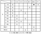
- 2 is an operation table showing a relationship between each shift stage of an automatic transmission included in the power transmission device of FIG. 1 and operation states of clutches and brakes.
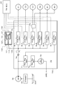
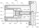
- It is a systematic diagram which shows the hydraulic control apparatus contained in the power transmission device of FIG. It is sectional drawing which shows the pressure accumulator of this indication. It is sectional drawing which shows the state by which the hydraulic pressure was stored in the pressure accumulator of FIG.
- FIG. 1 is a schematic configuration diagram of a power transmission device 20 including a pressure accumulator according to the present disclosure.
- a power transmission device 20 shown in the figure is connected to a crankshaft of an engine (not shown) mounted on a front wheel drive vehicle and can transmit power from the engine to left and right drive wheels (front wheels) (not shown).
- the power transmission device 20 includes a transmission case 22, a starting device (fluid transmission device) 23, an oil pump 24, an automatic transmission 25 housed in the transmission case 22, a gear mechanism (gear train) 40, A differential gear (differential mechanism) 50 and the like are included.
- a vehicle equipped with the power transmission device 20 stops the engine operation when the engine is normally idled when the vehicle stops, and restarts the engine in response to a start request to the vehicle by depressing the accelerator pedal. It is possible to execute idle stop control (automatic stop start control).
- the transmission case 22 is located between the converter housing 221 and the transaxle case 222 in addition to the converter housing 221 and the transaxle case 222 fastened (fixed) to the converter housing 221.
- the converter housing 221, the transaxle case 222, and the center support 224 are made of, for example, an aluminum alloy
- the front support 223 is made of a steel material (iron alloy) or an aluminum alloy.
- the starting device 23 includes a front cover connected to a crankshaft of an engine and / or a rotor of an electric motor via a drive plate or the like (not shown), and an input-side pump impeller having a pump shell closely fixed to the front cover. 23p, an output side turbine runner 23t connected to the input shaft 26 of the automatic transmission 25, the pump impeller 23p, and the turbine runner 23t are arranged inside the turbine runner 23t to rectify the flow of hydraulic oil from the turbine runner 23t to the pump impeller 23p.
- the stator 23s includes a one-way clutch 23o that is supported by a stator shaft (not shown) and restricts the rotational direction of the stator 23s to one direction. Pump impeller 23p, turbine runner 23t, and stator 23s constitute a torque converter having a torque amplifying action.
- the starting device 23 connects the front cover and the input shaft 26 of the automatic transmission 25 to each other and releases the connection between the front cover and the input shaft 26 of the automatic transmission 25.
- a damper device 23d for damping the vibration In the present embodiment, the lock-up clutch 23c is configured as a multi-plate friction type hydraulic clutch having a plurality of friction engagement plates (friction plates and separator plates). However, the lockup clutch 23c may be a single plate friction type hydraulic clutch.
- the starting device 23 may include a fluid coupling that does not include the stator 23s.
- the oil pump 24 includes an external gear (inner rotor) 241 connected to the pump impeller 23p of the starting device 23 through a winding transmission mechanism 240, an internal gear (outer rotor) 242 meshed with the external gear,
- a gear pump having a pump body (not shown) that defines a gear chamber (not shown) that accommodates the tooth gear 241 and the internal gear 242, a pump cover 245 (see FIG. 4), and the like, is configured as an input shaft 26 of the automatic transmission 25. It is arranged on another axis.
- the oil pump 24 is driven by the power from the engine via the winding transmission mechanism 240 and is stored in the hydraulic oil reservoir 225 (see FIG. 3) provided in the bottom of the transaxle case 222.
- the winding transmission mechanism 240 includes a drive sprocket that rotates integrally with the pump impeller 23p of the starting device 23, a driven sprocket that rotates integrally with the external gear of the oil pump 24, a drive sprocket, and a chain wound around the driven sprocket. .
- the automatic transmission 25 is configured as an eight-speed transmission, and as shown in FIG. 1, a double pinion type first planetary gear mechanism 30, a Ravigneaux type second planetary gear mechanism 35, and an input 4 clutches C1, C2, C3 and C4, two brakes B1 and B2, and a one-way clutch F1 for changing the power transmission path from the side to the output side.
- the first planetary gear mechanism 30 is engaged with a sun gear (fixed element) 31 that is an external gear and a ring gear 32 that is an internal gear arranged concentrically with the sun gear 31 and one of the gears is engaged with the sun gear 31.
- the other has a planetary carrier 34 that holds a plurality of pairs of two pinion gears 33a and 33b meshing with the ring gear 32 so as to be rotatable (rotatable) and revolved.
- the sun gear 31 of the first planetary gear mechanism 30 is non-rotatably connected (fixed) to the transmission case 22 via the front support 223, and the planetary carrier 34 of the first planetary gear mechanism 30 is
- the input shaft 26 is connected so as to be integrally rotatable.
- the first planetary gear mechanism 30 is configured as a so-called reduction gear, and decelerates the power transmitted to the planetary carrier 34 as an input element and outputs it from a ring gear 32 as an output element.
- the second planetary gear mechanism 35 includes a first sun gear 36a and a second sun gear 36b which are external gears, a ring gear 37 which is an internal gear disposed concentrically with the first and second sun gears 36a and 36b, A plurality of short pinion gears 38a meshing with one sun gear 36a, a plurality of long pinion gears 38b meshing with the second sun gear 36b and the plurality of short pinion gears 38a and meshing with the ring gear 37, a plurality of short pinion gears 38a and a plurality of long pinion gears 38b And a planetary carrier 39 that holds the magnet so as to be rotatable (rotatable) and revolved.
- the ring gear 37 of the second planetary gear mechanism 35 functions as an output member of the automatic transmission 25, and the power transmitted from the input shaft 26 to the ring gear 37 is transmitted to the left and right via the gear mechanism 40, the differential gear 50 and the drive shaft 51. Is transmitted to the driving wheel.
- the planetary carrier 39 is supported by the transmission case 22 via the one-way clutch F1, and the rotation direction of the planetary carrier 39 is limited to one direction by the one-way clutch F1.
- the clutch C1 connects the ring gear 32 of the first planetary gear mechanism 30 and the first sun gear 36a of the second planetary gear mechanism 35 to each other and releases the connection between them.
- the clutch C2 connects the input shaft 26 and the planetary carrier 39 of the second planetary gear mechanism 35 to each other and releases the connection between them.
- the clutch C3 connects the ring gear 32 of the first planetary gear mechanism 30 and the second sun gear 36b of the second planetary gear mechanism 35 to each other and releases the connection therebetween.
- the clutch C4 connects the planetary carrier 34 of the first planetary gear mechanism 30 and the second sun gear 36b of the second planetary gear mechanism 35 to each other and releases the connection therebetween.
- the clutches C1, C2, C3, and C4 include a piston, a plurality of friction engagement plates (friction plates and separator plates), an engagement oil chamber to which hydraulic oil is supplied, a centrifugal hydraulic pressure cancellation chamber, and the like.
- a multi-plate friction hydraulic clutch having a hydraulic servo is employed.
- the brake B1 fixes (connects) the second sun gear 36b of the second planetary gear mechanism 35 to the transmission case 22 in a non-rotatable manner and releases the second sun gear 36b from the transmission case 22.
- the brake B2 fixes the planetary carrier 39 of the second planetary gear mechanism 35 to the transmission case 22 so as not to rotate, and releases the fixation of the planetary carrier 39 to the transmission case 22.
- a multi-plate friction type having a hydraulic servo including a piston, a plurality of friction engagement plates (friction plates and separator plates), an engagement oil chamber to which hydraulic oil is supplied, and the like. A hydraulic brake is adopted.
- the one-way clutch F1 includes an inner race, an outer race, a plurality of sprags, a plurality of springs (plate springs), a cage, and the like that are connected (fixed) to the planetary carrier 39 of the second planetary gear mechanism 35.
- the one-way clutch F1 transmits torque via each sprag when the outer race rotates in one direction with respect to the inner race, and relatively rotates both when the outer race rotates in the other direction with respect to the inner race.
- the one-way clutch F1 may have a configuration other than a sprag type such as a roller type.
- FIG. 2 shows an operation table showing the relationship between the respective speeds of the automatic transmission 25 and the operating states of the clutches C1 to C4, the brakes B1 and B2, and the one-way clutch F1.
- the automatic transmission 25 shifts the forward first speed to the eighth speed and the reverse first speed and the second speed by setting the clutches C1 to C4 and the brakes B1 and B2 to the states shown in the operation table of FIG. Provide a step.
- at least one of the clutches C1 to C4 and the brakes B1 and B2 may be a meshing engagement element such as a dog clutch.
- the gear mechanism 40 is fixed to a counter drive gear 41 connected to the ring gear 37 of the second planetary gear mechanism 35 of the automatic transmission 25 and a counter shaft 42 extending in parallel with the input shaft 26 of the automatic transmission 25.
- a counter driven gear 43 that meshes with the counter drive gear 41, a drive pinion gear 44 formed (or fixed) on the counter shaft 42, and a diff ring gear 45 that meshes with the drive pinion gear 44 and is connected to the differential gear 50.
- the counter drive gear 41 of the gear mechanism 40 is fixed to the transaxle case 222 via a plurality of bolts so as to be positioned between the first and second planetary gear mechanisms 30 and 35.
- the support 224 is rotatably supported through a bearing.
- FIG. 3 is a system diagram showing the hydraulic control device 70.
- the hydraulic control device 70 is connected to the above-described oil pump 24 that is driven by power from the engine and sucks and discharges hydraulic oil from the hydraulic oil reservoir 225 of the transaxle case 222 via the strainer 60.
- the hydraulic pressure required by the automatic transmission 25 is generated, and hydraulic oil is supplied to lubrication targets such as various bearings.
- the hydraulic control device 70 adjusts hydraulic oil from the valve body 700 and the oil pump 24 to generate a line pressure PL, a primary regulator valve 71, a secondary regulator valve 72, an oil cooler 73, a check valve 74, an apply control valve.
- valve body 700 is attached to a side portion of the transaxle case 222 constituting the transmission case 22.
- the primary regulator valve 71 generates a line pressure using the hydraulic pressure from the linear solenoid valve SLT as a signal pressure.
- the linear solenoid valve SLT adjusts hydraulic oil from the oil pump 24 side (for example, a modulator valve (not shown) that regulates the line pressure PL and outputs a constant hydraulic pressure) to adjust the throttle opening of the vehicle or the throttle valve. Control is performed by a shift electronic control unit (hereinafter referred to as “TMECU”) 90 so as to output the corresponding hydraulic pressure.
- TMECU shift electronic control unit
- the secondary regulator valve 72 regulates the hydraulic oil drained from the primary regulator valve 71 to generate a secondary pressure (circulation pressure) Psec.
- the oil cooler 73 cools the hydraulic oil drained from the secondary regulator valve 72 and supplied to the lubrication target.
- the check valve 74 is connected to the pressure regulating port of the primary regulator valve 71 and restricts the hydraulic oil from the oil pump 24 side from flowing back to the primary regulator valve 71 side.
- the linear solenoid valves SL1, SL2, SL3, SL4 and SL5 are connected to the output port of the check valve 74, respectively, and adjust the line pressure PL as the original pressure supplied from the primary regulator valve 71 to correspond to the clutch. Generate hydraulic pressure to etc.
- the linear solenoid valve SL1 is a normally closed linear solenoid valve that adjusts the line pressure PL, which is the original pressure, according to the applied current to generate a hydraulic pressure (engagement hydraulic pressure) to the clutch C1.
- the linear solenoid valve SL2 is a normally closed linear solenoid valve that adjusts the line pressure PL, which is the original pressure, according to the applied current to generate a hydraulic pressure (engagement hydraulic pressure) to the clutch C2.
- the linear solenoid valve SL3 is a normally closed linear solenoid valve that adjusts the line pressure PL, which is the original pressure, in accordance with the applied current to generate a hydraulic pressure (engagement hydraulic pressure) to the clutch C3.
- the linear solenoid valve SL4 is a normally closed linear solenoid valve that adjusts the line pressure PL, which is the original pressure, according to the applied current to generate a hydraulic pressure (engagement hydraulic pressure) to the clutch C4.
- the linear solenoid valve SL5 is a normally closed linear solenoid valve that adjusts the line pressure PL, which is the original pressure, according to the applied current to generate a hydraulic pressure (engagement hydraulic pressure) to the brake B1.
- the apply control valve 75 has a first state in which the hydraulic pressure from the linear solenoid valve SL3 can be supplied to the clutch C3 (only), and a second state in which the hydraulic pressure from the linear solenoid valve SL3 can be supplied to the brake B2 (only).
- the spool valve can be formed selectively.
- the apply control valve 75 forms the first state when a shift lever (not shown) is set in the drive range, and the shift lever is in a shift range other than the drive range (parking range, neutral range and reverse range). Is set to form the second state.
- the signal pressure of the apply control valve 75 may be a line pressure PL, a modulator pressure generated by the modulator valve, or the like, or may be output from a duty solenoid valve (not shown).
- the above-described linear solenoid valves SL1, SL2, SL3, SL4 and SL5 are controlled by the TMECU 90.
- the hydraulic pressures to the clutches C1, C2, C3 and C4 and the brakes B1 and B2 of the automatic transmission 25 are directly controlled (set) by the corresponding linear solenoid valves SL1, SL2, SL3, SL4 or SL5.
- the TMECU 90 corresponds to a clutch or the like that is engaged with a change in the shift speed so that a target shift speed corresponding to the accelerator opening and the vehicle speed acquired from a predetermined shift map (not shown) is formed.
- Hydraulic pressure command values (engagement pressure command values) to the linear solenoid valves SL1 to SL5 and hydraulic pressure command values (release pressures) to the linear solenoid valves SL1 to SL5 corresponding to clutches and the like that are released when the gear position is changed. Command value). Further, the TMECU 90 sets hydraulic pressure command values (holding pressure command values) to the linear solenoid valves SL1 to SL5 corresponding to the engaged clutches and brakes (engagement elements) during the shift stage change or after the shift is completed.
- the TMECU 90 has the above-described hydraulic pressure command values, that is, the engagement pressure command value, the release pressure command value, in cooperation with hardware such as CPU, ROM, and RAM and software such as a control program installed in the ROM.
- a shift control module (not shown) for setting the holding pressure command value is constructed as a functional block.
- the vehicle on which the power transmission device 20 is mounted is capable of executing engine idle stop control.
- the engine stop operation is performed after the idle stop control is performed, the engine is stopped.
- the oil pump 24 also stops and the line pressure PL decreases. Accordingly, when the operation of the oil pump 24 is stopped, the hydraulic pressure (from the linear solenoid valve SL1 corresponding to the clutch C1 serving as the starting clutch engaged when the automatic transmission 25 is set at the first forward speed (starting stage) is set. (Engagement hydraulic pressure) cannot be supplied.
- an accumulator (pressure accumulator) 100 is connected to the hydraulic control device 70 of the power transmission device 20 in order to supply hydraulic pressure to the clutch C ⁇ b> 1 from other than the oil pump 24. .
- the accumulator 100 can store a hydraulic pressure sufficient to fully engage the clutch C1, and in this embodiment, the valve body 700 is interposed between the check valve 74 and the input port of the linear solenoid valve SL1. Is connected to a supply oil passage L1 for supplying hydraulic pressure from the oil pump 24 to the clutch C1.
- the accumulator 100 includes a housing 101, a piston 120 that is movably disposed in the housing 101 and defines a pressure accumulating chamber 150 together with the housing 101, and a side opposite to the pressure accumulating chamber 150 with respect to the piston 120. And a spring (biasing member) 130 that is disposed in the housing 101 and biases the piston 120 toward the pressure accumulation chamber 150.
- the oil supply passage 110 is connected to the supply oil passage L ⁇ b> 1 and extends along the moving direction of the piston 120, and the oil from the supply / discharge oil passage 110 to the pressure accumulating chamber 150.
- a solenoid valve S1 that allows inflow and allows oil outflow from the pressure accumulation chamber 150 to the supply / discharge oil passage 110 is disposed.
- the solenoid valve S1 is a normally closed on / off valve having a check valve CV built in the spool or the sleeve, in addition to the spool (valve element), the sleeve for housing the spool, and the solenoid portion SL.
- the check valve CV built in the solenoid valve S1 allows the hydraulic oil to flow from the supply / discharge oil passage 110 to the pressure accumulation chamber 150 when no current is applied to the solenoid portion SL, that is, when the solenoid valve S1 is closed. At the same time, the outflow of hydraulic oil from the pressure accumulation chamber 150 to the supply / discharge oil passage 110 is restricted. Further, the solenoid valve S1 allows the hydraulic oil to flow out from the pressure accumulating chamber 150 to the supply / discharge oil passage 110 when current is applied to the solenoid portion SL, that is, when the valve is opened.
- the solenoid valve S1 of the accumulator 100 is controlled by the TMECU 90, and the TMECU 90 maintains the solenoid valve S1 in a closed state when the engine is operated and the oil pump 24 generates hydraulic pressure.
- a part of the hydraulic oil (line pressure PL) that has been discharged from the oil pump 24 and then regulated by the primary regulator valve 71 is supplied from the supply oil passage L1 to the accumulator 100. It flows into the pressure accumulating chamber 150 through the oil drain passage 110 and the check valve CV.
- the hydraulic oil flowing into the pressure accumulating chamber 150 can move the piston 120 against the biasing force of the spring 130, and the hydraulic pressure can be stored in the pressure accumulating chamber 150.
- the check valve CV restricts the flow of hydraulic oil from the pressure accumulation chamber 150 to the supply oil passage L1, so that even if the contraction of the spring 130 is not regulated, The hydraulic pressure corresponding to the contraction amount of the spring 130 can be stored.
- the TMECU 90 turns on the solenoid valve S1 at the timing before the engine is restarted after the engine operation is stopped by the idle stop control or when the engine is restarted, and corresponds to the clutch C1.
- the linear solenoid valve SL1 is opened.
- the oil flows out from the accumulator 100 of the accumulator 100 to the supply oil passage L1 through the oil passage in the linear solenoid valve SL1 opened by the valve body and the supply / discharge oil passage 110, and the linear solenoid valve SL1 is turned off.
- the hydraulic pressure can be supplied to the clutch C1, which is the starting clutch, to engage the clutch C1.
- FIG. 4 is a sectional view showing the accumulator 100.
- the housing 101 of the accumulator 100 is formed by casting an iron alloy or an aluminum alloy, and has a diameter from a cylindrical tubular portion (outer tubular portion) 102 and one end (left end in FIG. 4) of the tubular portion 102.
- An annular end wall 103 extending inward in the direction and an annular end extending radially outward from the other end (right end in FIG. 4) of the cylindrical portion 102, that is, the end opposite to the end wall 103.
- the fastening portion 104 and the inner tubular portion 105 extending in parallel with the tubular portion 102 from the inner periphery of the end wall portion 103 toward the fastening portion 104 side.
- the fastening portion 104 of the housing 101 is fastened (fixed) to, for example, a pump cover 245 that is a constituent member of the power transmission device 20 via a plurality of bolts B, and the housing 101 (fastening portion 104).
- a plate 140 is interposed between the pump cover 245 and the pump cover 245.
- the pump cover 245 is fastened (fixed) to the front support 223 together with a pump body (not shown).
- the pump cover 245 has a supply oil passage L1 (return check) formed in the valve body 700 of the hydraulic control device 70.
- a communication oil passage 247 communicating with the valve 74 and the input port of the linear solenoid valve SL1 is formed.
- the communication oil passage 247 extends in a direction perpendicular to the axis of the cylindrical portion 102 of the housing 101 (see the one-dot chain line in FIG. 4) and parallel to the axis of the cylindrical portion 102. Part.
- a solenoid valve S1 is disposed in the inner cylinder portion 105 of the housing 101 so that the whole is close to the end wall portion 103 and the spool (valve element) extends in parallel with the axis of the cylindrical portion 102.
- the oil supply / discharge oil passage 110 is defined so as to be further away from the end wall portion 103 than the solenoid valve S1. That is, the supply / discharge oil passage 110 is arranged so as to be aligned in the moving direction of the solenoid valve S1 and the piston 120, and communicates with the supply oil passage L1 on the side opposite to the solenoid valve S1.
- the inner cylindrical portion 105 of the housing 101 extends in parallel and coaxially with the axial center of the cylindrical portion 102, and a cylindrical large-diameter portion 106 that extends from the inner periphery of the end wall portion 103.
- the intermediate portion 107 is smaller in diameter and cylindrical than the large diameter portion 106, and the small diameter portion 108 is smaller in diameter and cylindrical than the intermediate portion 107.
- a solenoid portion SL of the solenoid valve S1 is disposed in the large diameter portion 106 of the inner cylinder portion 105, and the solenoid valve S1 is supported by the end wall portion 103 of the housing 101 via a snap ring.
- a plurality of oil inflow / outflow ports 107o are formed at intervals in the circumferential direction at the intermediate portion 107 of the inner cylinder portion 105, and the spool of the solenoid valve S1 projects into the intermediate portion 107. .
- the small diameter part 108 of the inner cylinder part 105 penetrates the piston 120, and the supply / discharge oil passage 110 is defined in the small diameter part 108 so as to be positioned on the axial center of the cylindrical part 102.
- the distal end (the right end in FIG. 4) of the small diameter portion 108 of the inner cylinder portion 105 abuts on the plate 140 described above, and the supply / discharge oil passage 110 communicates with the pump cover 245 through a communication hole 145 formed in the plate 140.
- the oil passage 247 communicates.
- a gasket (not shown) is attached to the front and back surfaces of the plate 140 so as to surround at least the periphery of the communication hole 145.
- the dimensions of the housing 101 and the pump cover 245 are increased as compared with the case where a seal ring or the like is disposed between the housing 101 and the pump cover 245. This makes it possible to satisfactorily seal the communication portion between the supply / discharge oil passage 110 and the communication oil passage 247.
- the piston 120 of the accumulator 100 has an annular first pressure receiving portion 121 having an opening through which the small diameter portion 108 of the inner cylindrical portion 105 of the housing 101 is inserted, and a shaft extending from the outer periphery of the first pressure receiving portion 121.
- a cylindrical barrel 122 extending in the direction (moving direction of the piston 120), and an annular shape extending radially outward from the free end of the barrel 122, that is, the end opposite to the first pressure receiving portion 121
- the second pressure receiving portion 123 The second pressure receiving portion 123.
- the piston 120 is configured such that the second pressure receiving portion 123 is located closer to the end wall portion 103 than the first pressure receiving portion 121 and is separated from the supply / exhaust oil passage 110 and the body portion 122 at least partially covers the solenoid valve S1. It arrange
- An annular seal groove is formed on the inner peripheral surface of the first pressure receiving portion 121, and a seal member 126 such as an O-ring that slides on the outer peripheral surface of the small diameter portion 108 of the inner cylinder portion 105 is formed in the seal groove. Is placed.
- an annular seal groove is formed on the outer peripheral surface of the second pressure receiving portion 123, and a seal member 127 such as an O-ring that slides on the inner peripheral surface of the cylindrical portion 102 is disposed in the seal groove. Is done.
- an annular protrusion that protrudes away from the second pressure receiving portion 123 toward the inner peripheral side from the outer peripheral side to the inner peripheral portion of the end surface of the first pressure receiving portion 121 facing the plate 140 (pump cover 245).
- a portion 121a is formed.
- an annular protrusion 123 a that protrudes away from the first pressure receiving portion 121 as it goes from the outer peripheral side to the inner peripheral side is formed on the inner peripheral portion of the end surface facing the end wall portion 103 of the second pressure receiving portion 123. Is formed.
- the spring 130 of the accumulator 100 is provided between the second pressure receiving portion 123 of the piston 120 and the plate 140 (pump cover 245), that is, the supply oil passage L ⁇ b> 1 in the moving direction of the piston with respect to the piston 120. Placed on the side.
- the spring 130 is a compression coil spring that is disposed so as to surround the body portion 122 of the piston 120 and to come into contact with the back surface (the right end surface in FIG. 4) of the second pressure receiving portion 123.
- the housing 101 includes an inner peripheral surface of the cylindrical portion 102, an inner end surface of the end wall portion 103, an outer peripheral surface of the inner cylindrical portion 105 (the large diameter portion 106, the intermediate portion 107, and the small diameter portion 108), a piston.
- a pressure accumulating chamber 150 is defined by the end faces (left end face in FIG. 4) of 120 first pressure receiving portions 121 and second pressure receiving portions 123 and the inner peripheral surface of body portion 122. That is, the pressure accumulating chamber 150 is defined on the solenoid valve S1 side in the moving direction of the piston 120 with respect to the piston 120, and communicates with the middle portion 107 of the inner cylinder portion 105 through the plurality of oil inflow / outlet ports 107o.
- the spring 130 is positioned on the opposite side of the pressure accumulation chamber 150 with respect to the piston 120 and biases the piston 120 toward the pressure accumulation chamber 150 (end wall portion 103).
- a supply / discharge oil passage 110 that communicates with the supply oil passage L1 and extends through the piston 120 along the moving direction of the piston 120 in the cylindrical portion 102 of the housing 101;
- a solenoid valve S1 that allows the hydraulic oil to flow from the passage 110 to the pressure accumulation chamber 150 and allows the hydraulic oil to flow from the pressure accumulation chamber 150 to the supply / discharge oil passage 110 is disposed.
- the solenoid valve S1 check valve CV
- the piston 120 supplies and discharges oil against the urging force of the spring 130.
- the hydraulic oil in the passage 110 moves in the direction opposite to the traveling direction.
- both the supply / discharge oil passage 110 and the solenoid valve S1 can be disposed in the housing 101 while enabling the supply oil passage L1 (communication oil passage 247) and the pressure accumulating chamber 150 to communicate with each other.
- the supply oil passage L1 communication oil passage 247
- the pressure accumulating chamber 150 to communicate with each other.
- the accumulator 100 does not require a holding mechanism for locking the piston 120, as in an oil storage device (see Patent Document 2) that unlocks the piston by an electromagnetic actuator.
- Patent Document 2 that unlocks the piston by an electromagnetic actuator.
- the piston 120 includes the annular first pressure receiving portion 121, the body portion 122 extending from the outer periphery of the first pressure receiving portion 121 along the moving direction of the piston, and the first of the body portion 122.
- An annular second pressure receiving portion 123 extending radially outward from the end opposite to the pressure receiving portion 121 is provided.
- the second pressure receiving portion 123 is located on the end wall 103 side of the first pressure receiving portion 121 and is separated from the supply / discharge oil passage 110, and the body portion 122 at least partially surrounds the solenoid valve S1. It arrange
- the oil supply / discharge oil passage 110 is provided on the axial center of the cylindrical portion 102 and penetrates the first pressure receiving portion 121 of the piston 120, and the spring 130 surrounds the body portion 122 of the piston 120 and the second pressure receiving pressure. It arrange
- the stroke of the piston 120 that is, the volume of the pressure accumulating chamber 150 is satisfactorily secured while suppressing an increase in the dimension (axial length) of the housing 101 (cylindrical portion 102) in the extending direction of the axial center of the cylindrical portion 102. It becomes possible to do.
- the housing 101 includes an annular end wall portion 103 that extends radially inward from one end (the left end in FIGS. 4 and 4) of the cylindrical portion 102, and an inner periphery of the end wall portion 103. And an inner cylinder portion 105 extending in parallel with the cylindrical portion 102 and penetrating the piston 120.
- the solenoid valve S1 is disposed in the inner cylinder portion 105 so as to be close to the end wall portion 103, and the supply / discharge oil passage 110 is separated from the end wall portion 103 more than the solenoid valve S1. It is defined within. As a result, it is possible to provide the oil supply / discharge oil passage 110 penetrating the piston 120 in the cylindrical portion 102 while disposing the solenoid valve S1 in the cylindrical portion 102 of the housing 101.
- the inner cylinder portion 105 of the housing 101 includes the large-diameter portion 106 where the solenoid portion SL of the solenoid valve S1 is disposed, and the oil that is smaller in diameter than the large-diameter portion 106 and communicates with the pressure accumulating chamber 150. It has an intermediate portion 107 having an inflow / outlet port 107o, and a small diameter portion 108 that is smaller in diameter than the intermediate portion 107 and penetrates the piston 120 and in which the supply / discharge oil passage 110 is defined. As a result, the space occupied by the inner cylindrical portion 105 in the cylindrical portion 102 can be reduced, and the volume of the pressure accumulating chamber 150 can be secured satisfactorily.
- the solenoid valve S1 allows the hydraulic oil to flow from the supply / discharge oil passage 110 to the pressure accumulation chamber 150 when the valve is closed, and allows the hydraulic oil to flow from the pressure accumulation chamber 150 to the supply / discharge oil passage 110. It has a check valve CV that regulates, and allows hydraulic oil to flow from the pressure accumulator 150 to the supply / discharge oil passage 110 when the valve is opened. As a result, when the solenoid valve S1 is closed, the hydraulic oil is allowed to flow from the supply oil passage L1 into the pressure accumulation chamber 150 via the supply / discharge oil passage 110, and from the pressure accumulation chamber 150 to the supply / discharge oil passage 110, that is, the supply oil passage L1.
- the solenoid valve S1 may allow or restrict the communication between the oil supply / discharge oil passage 110 and the pressure accumulation chamber 150 without having the check valve CV.
- the accumulator 100 (housing 101) is attached to the pump cover 245 constituting the oil pump 24.
- the accumulator 100 (housing 101) is attached to the constituent members of the power transmission device 20 other than the pump cover 245. May be.
- the accumulator 100 may be provided with another urging member such as a diaphragm instead of the spring 130.
- the pressure accumulator has the engagement element (C1) of the transmission (25) engaged with the hydraulic pressure from the oil pump (24) driven by the prime mover of the vehicle when the vehicle starts.
- the housing (101) including the cylindrical portion (102) and the pressure accumulating chamber (150) together with the cylindrical portion (102) are provided.
- a piston (120) that is movably disposed in the cylindrical part (102) so as to define, and the supply oil passage (L1) side of the pressure accumulation chamber (150) with respect to the piston (120)
- An urging member (130) disposed in the cylindrical portion (102) to urge the piston (120) toward the pressure accumulating chamber (102), and the supply oil passage (L1).
- the pressure accumulator of the present disclosure is connected to a supply oil passage for supplying hydraulic pressure from an oil pump to an engagement element of a transmission that is engaged when the vehicle starts. And in this pressure accumulator, the energizing member which is located in the supply oil path side rather than the accumulator room with respect to the piston in the cylindrical part of the housing, and communicates with the supply oil path.
- a supply / discharge oil passage that extends through the piston through the piston and a solenoid valve that communicates the supply / discharge oil passage and the pressure accumulating chamber and cancels the communication therebetween are disposed.
- both the supply / discharge oil passage and the solenoid valve can be arranged in the housing while enabling communication between the supply oil passage and the pressure accumulating chamber, the oil passage is secured in the housing (tubular portion). There is no need to provide a protrusion or the like. Further, in this pressure accumulator, a holding mechanism for locking the piston is not required, unlike an oil accumulator that unlocks the piston by an electromagnetic actuator. As a result, it is possible to suppress complication of the shape of the housing and further improve the mountability of the pressure accumulator.
- the supply / discharge oil passage (110) is disposed between the solenoid valve (S1) and the supply oil passage (L1) in the moving direction of the piston (120), and the solenoid valve (S1).
- the pressure accumulation chamber (150) may be connected to the solenoid valve (S1) side in the moving direction of the piston with respect to the piston (120).
- the biasing member (130) may be arranged on the supply oil passage (L1) side in the moving direction of the piston with respect to the piston (120).
- the piston (120) includes an annular first pressure receiving part (121), a body part (122) extending from an outer periphery of the first pressure receiving part (121), and a free play of the body part (122).
- An annular second pressure receiving portion (123) extending radially outward from the end, and the first pressure receiving portion (121) is further away from the solenoid valve (S1) than the second pressure receiving portion (123).
- the barrel portion (122) may be disposed in the cylindrical portion (102) so as to be separated and at least partially surround the solenoid valve (S1), and the oil supply / discharge passage (110) may be
- the biasing member (130) may be provided on the axial center of the cylindrical part (102) and may pass through the first pressure receiving part (121) of the piston (120).
- the housing (101) includes an annular end wall portion (103) extending radially inward from one end of the cylindrical portion (102), and an inner periphery of the end wall portion (103).
- An inner cylinder portion (105) extending in parallel with the shape portion (102) and penetrating the piston (120), and the solenoid valve (S1) is adjacent to the end wall portion (103).
- the inner cylinder portion (105) may be disposed in the inner cylinder portion (105), and the oil supply / discharge oil passage (110) is separated from the end wall portion (103) more than the solenoid valve (S1). It may be defined in the section (105). Accordingly, it is possible to provide a supply / discharge oil passage that penetrates the piston in the cylindrical portion while arranging the solenoid valve in the cylindrical portion of the housing.
- the housing (101) may further include a fastening portion (104) provided at an end of the tubular portion (102) opposite to the end wall portion (103). 104) may be fastened to a component member (245) of the power transmission device (20) including the transmission (25), and the component member (245) of the power transmission device (20)
- a communication oil passage (247) that allows the passage (L1) and the supply / discharge oil passage (110) to communicate with each other may be provided, and the urging member (130) is the constituent member of the power transmission device (20). (245) and the piston (120).
- the inner cylinder part (105) has a large-diameter part (106) where the solenoid part of the solenoid valve (S1) is arranged, and a smaller diameter than the large-diameter part, and is placed in the pressure accumulation chamber (150).
- An intermediate portion (107) having an oil inflow / outflow port (107o) communicating with the intermediate portion (107) and a smaller diameter than the intermediate portion and penetrating the piston (120), and the supply / discharge oil passage (110) is defined therein.
- the solenoid valve (S1) allows oil to flow from the supply / discharge oil passage (110) to the pressure accumulation chamber (150) when the valve is closed, and from the pressure accumulation chamber (150) to the supply / discharge oil passage ( A check valve (CV) that regulates oil outflow to 110) may be provided, and oil outflow from the pressure accumulating chamber (150) to the supply / discharge oil passage (110) may be allowed when the valve is opened.
- a check valve (CV) that regulates oil outflow to 110
- CV that regulates oil outflow to 110
- the oil that has flowed into the pressure accumulating chamber can move the piston against the urging force of the urging member, and the hydraulic pressure can be stored in the pressure accumulating chamber. Furthermore, by opening the solenoid valve, the oil can flow out from the pressure accumulating chamber to the supply oil passage through the supply / discharge oil passage, and the hydraulic pressure can be supplied to the engagement element that is engaged when the vehicle starts. It becomes.
- the invention of the present disclosure can be used in the power transmission device manufacturing industry and the like.
Landscapes
- Engineering & Computer Science (AREA)
- Physics & Mathematics (AREA)
- Fluid Mechanics (AREA)
- Mechanical Engineering (AREA)
- General Engineering & Computer Science (AREA)
- Control Of Transmission Device (AREA)
Abstract
アキュムレータ100は、筒状部102を含むハウジング101と、筒状部102と共に蓄圧室150を画成するように当該筒状部102内に移動自在に配置されるピストン120と、ピストン120よりも供給油路L1側に位置するように筒状部102内に配置されるスプリング130と、オイルポンプからの油圧を発進クラッチに供給するための供給油路L1に連通すると共に、筒状部102内でピストン120を貫通して当該ピストン120の移動方向に沿って延びる給排油路110と、筒状部102内に配置されて給排油路110と蓄圧室150との連通と遮断とを切り替えるソレノイドバルブS1とを含む。
Description
本開示の発明は、油圧を蓄える蓄圧装置に関する。
従来、車両用駆動装置として、エンジンにより駆動されるオイルポンプと、オイルポンプに油路を介して接続された前進用クラッチと、当該油路から分岐された分岐油路を介してオイルポンプにより発生させられた油圧を蓄えるアキュムレータと、オイルポンプの停止中に分岐油路を閉状態にしてアキュムレータの油圧を保持すると共に、オイルポンプの駆動開始時または駆動開始前に分岐油路を開状態にしてアキュムレータに蓄えられた油圧を前進用クラッチに供給する電磁開閉弁とを含むものが知られている(例えば、特許文献1参照)。この車両用駆動装置では、車両が停止すると判断され、かつ、アキュムレータに蓄えられた油圧が必要圧以下である場合、エンジンの停止前に電磁開閉弁が開弁させられ、それによりアキュムレータの油圧が高められる。
また、上述のような用途に適用され得る蓄油装置として、ハウジングと、ハウジング内に移動自在に配置されて当該ハウジングの一端側に油室を画成するピストンと、当該ピストンをハウジングの一端側に付勢するスプリングと、油室内への油の充填に伴ってピストンと係合してスプリングの付勢力によりピストンが上記一端側に移動するのを規制する保持機構と、ハウジングの他端側に位置するように当該ハウジング内に配置されると共に通電時に保持機構によるピストンのロックを解除する電磁アクチュエータとを含むものが知られている(例えば、特許文献2参照)。この蓄油装置では、一方向スロットルバルブを介して油室内に油圧系統からの油が流入すると、ピストンがスプリングの付勢力に抗して当該油室内への油の流入方向と同方向に移動し、ピストンの爪部(29)が電磁アクチュエータにより制御される保持機構(30)によりロックされることで油室内に油が蓄えられる。そして、電磁アクチュエータによりピストンのロックが解除されると、スプリングの付勢力によりピストンが一端側に移動し、それにより油室内の油が油圧系統へと流出する。
特許文献1に記載されたような用途に適用される蓄圧装置には、要求される油圧を蓄えることができるように、比較的容積の大きい油室(蓄圧室)と、高い剛性を有するスプリングとが設けられ、更に当該蓄圧装置とオイルポンプとの間には、電磁開閉弁が設けられる。従って、かかる蓄圧装置は、他の用途に用いられるものに比べて大型化しがちであり、変速機等への搭載性の面で課題を有している。更に、蓄圧装置の油室の油流入出口を開閉する電磁弁を特許文献2に記載されたものと同様にしてハウジング内に配置しようとすると、油路の取り回しに伴ってハウジング等の形状が複雑化し、蓄圧装置の搭載性が悪化してしまうおそれがある。一方、電磁アクチュエータによりピストンのロックを解除する蓄油装置であれば、電磁アクチュエータを特許文献2に記載にされたように比較的容易にハウジング内に配置することができる。しかしながら、特許文献2に記載された蓄圧装置は、ピストンの爪部(29)と、当該爪部をロックするための保持機構とを必要とする点で、搭載性の面で、なお改善の余地を有している。
そこで、本開示の発明は、蓄圧装置の搭載性をより向上させることを主目的とする。
本開示の蓄圧装置は、車両の原動機により駆動されるオイルポンプからの油圧を前記車両の発進時に係合される変速機の係合要素に供給するための供給油路に接続される蓄圧装置において、筒状部を含むハウジングと、前記筒状部と共に蓄圧室を画成するように該筒状部内に移動自在に配置されるピストンと、前記ピストンよりも前記供給油路側に位置するように前記筒状部内に配置され、前記ピストンを前記蓄圧室側に付勢する付勢部材と、前記供給油路に連通すると共に、前記筒状部内で前記ピストンを貫通して該ピストンの移動方向に沿って延びる給排油路と、前記筒状部内に配置され、前記給排油路と前記蓄圧室との連通と遮断とを切り替えるソレノイドバルブとを備えるものである。
この蓄圧装置は、オイルポンプからの油圧を車両の発進時に係合される変速機の係合要素に供給するための供給油路に接続されるものである。そして、この蓄圧装置では、ハウジングの筒状部内に、ピストンよりも供給油路側に位置して当該ピストンを蓄圧室側に付勢する付勢部材と、供給油路に連通すると共にピストンを貫通して当該ピストンの移動方向に沿って延びる給排油路と、給排油路と蓄圧室とを連通すると共に両者の連通を解除するソレノイドバルブとが配置される。これにより、供給油路と蓄圧室との連通を可能としつつ、給排油路およびソレノイドバルブの双方をハウジング内に配置することができるので、ハウジング(筒状部)に油路を確保するための突出部等を設ける必要がなくなる。また、この蓄圧装置では、電磁アクチュエータによりピストンのロックを解除する蓄油装置のように、ピストンをロックするための保持機構が不要となる。この結果、ハウジングの形状の複雑化を抑制し、蓄圧装置の搭載性をより向上させることが可能となる。
次に、図面を参照しながら、本開示の発明を実施するための形態について説明する。
図1は、本開示の蓄圧装置を含む動力伝達装置20の概略構成図である。同図に示す動力伝達装置20は、前輪駆動車両に搭載される図示しないエンジンのクランクシャフトに接続されると共にエンジンからの動力を図示しない左右の駆動輪(前輪)に伝達可能なものである。図示するように、動力伝達装置20は、トランスミッションケース22や、発進装置(流体伝動装置)23、オイルポンプ24、トランスミッションケース22内に収容される自動変速機25、ギヤ機構(ギヤ列)40、デファレンシャルギヤ(差動機構)50等を含む。また、動力伝達装置20が搭載される車両は、停車に伴って通常エンジンがアイドル運転される際等にエンジンの運転を停止させると共にアクセルペダルの踏み込みによる車両に対する発進要求に応じてエンジンを再始動させるアイドルストップ制御(自動停止始動制御)を実行可能なものである。
トランスミッションケース22は、コンバータハウジング221や、当該コンバータハウジング221に締結(固定)されるトランスアクスルケース222に加えて、コンバータハウジング221とトランスアクスルケース222との間に位置するように当該トランスアクスルケース222に締結(固定)されるフロントサポート223、およびトランスアクスルケース222に締結(固定)されるセンターサポート224を含む。本実施形態において、コンバータハウジング221、トランスアクスルケース222、およびセンターサポート224は、例えばアルミニウム合金により形成され、フロントサポート223は、鋼材(鉄合金)またはアルミニウム合金により形成される。
発進装置23は、図示しないドライブプレート等を介してエンジンのクランクシャフトおよび/または電気モータのロータに連結されるフロントカバーや、当該フロントカバーに密に固定されるポンプシェルを有する入力側のポンプインペラ23p、自動変速機25の入力軸26に連結される出力側のタービンランナ23t、ポンプインペラ23pおよびタービンランナ23tの内側に配置されてタービンランナ23tからポンプインペラ23pへの作動油の流れを整流するステータ23s、図示しないステータシャフトより支持されると共にステータ23sの回転方向を一方向に制限するワンウェイクラッチ23o等を含む。ポンプインペラ23p、タービンランナ23tおよびステータ23sは、トルク増幅作用を有するトルクコンバータを構成する。
更に、発進装置23は、フロントカバーと自動変速機25の入力軸26とを互いに接続すると共に両者の接続を解除するロックアップクラッチ23cと、フロントカバーと自動変速機25の入力軸26との間で振動を減衰するダンパ装置23dとを含む。本実施形態において、ロックアップクラッチ23cは、複数の摩擦係合プレート(摩擦プレートおよびセパレータプレート)を有する多板摩擦式油圧クラッチとして構成される。ただし、ロックアップクラッチ23cは、単板摩擦式油圧クラッチであってもよい。また、発進装置23は、ステータ23sを有さない流体継手を含むものであってもよい。
オイルポンプ24は、巻掛け伝動機構240を介して発進装置23のポンプインペラ23pに連結される外歯ギヤ(インナーロータ)241、当該外歯ギヤに噛合する内歯ギヤ(アウターロータ)242、外歯ギヤ241および内歯ギヤ242を収容する図示しないギヤ室を画成するポンプボディ(図示省略)およびポンプカバー245(図4参照)等を有するギヤポンプとして構成され、自動変速機25の入力軸26とは別軸上に配置される。オイルポンプ24は、巻掛け伝動機構240を介してエンジンからの動力により駆動され、トランスアクスルケース222の底部に設けられた作動油貯留部225(図3参照)に貯留されている作動油(ATF)を吸引して油圧制御装置70へと圧送する。巻掛け伝動機構240は、発進装置23のポンプインペラ23pと一体に回転するドライブスプロケットや、オイルポンプ24の外歯ギヤと一体に回転するドリブンスプロケット、ドライブスプロケットおよびドリブンスプロケットに巻掛けられるチェーンを含む。
自動変速機25は、8段変速式の変速機として構成されており、図1に示すように、ダブルピニオン式の第1遊星歯車機構30と、ラビニヨ式の第2遊星歯車機構35と、入力側から出力側までの動力伝達経路を変更するための4つのクラッチC1,C2,C3およびC4、2つのブレーキB1およびB2、並びにワンウェイクラッチF1とを含む。
第1遊星歯車機構30は、外歯歯車であるサンギヤ(固定要素)31と、このサンギヤ31と同心円上に配置される内歯歯車であるリングギヤ32と、互いに噛合すると共に一方がサンギヤ31に、他方がリングギヤ32に噛合する2つのピニオンギヤ33a,33bの組を自転自在(回転自在)かつ公転自在に複数保持するプラネタリキャリヤ34とを有する。図示するように、第1遊星歯車機構30のサンギヤ31は、フロントサポート223を介してトランスミッションケース22に対して回転不能に連結(固定)されており、第1遊星歯車機構30のプラネタリキャリヤ34は、入力軸26に一体回転可能に接続されている。また、第1遊星歯車機構30は、いわゆる減速ギヤとして構成されており、入力要素であるプラネタリキャリヤ34に伝達された動力を減速して出力要素であるリングギヤ32から出力する。
第2遊星歯車機構35は、外歯歯車である第1サンギヤ36aおよび第2サンギヤ36bと、第1および第2サンギヤ36a,36bと同心円上に配置される内歯歯車であるリングギヤ37と、第1サンギヤ36aに噛合する複数のショートピニオンギヤ38aと、第2サンギヤ36bおよび複数のショートピニオンギヤ38aに噛合すると共にリングギヤ37に噛合する複数のロングピニオンギヤ38bと、複数のショートピニオンギヤ38aおよび複数のロングピニオンギヤ38bを自転自在(回転自在)かつ公転自在に保持するプラネタリキャリヤ39とを有する。第2遊星歯車機構35のリングギヤ37は、自動変速機25の出力部材として機能し、入力軸26からリングギヤ37に伝達された動力は、ギヤ機構40、デファレンシャルギヤ50およびドライブシャフト51を介して左右の駆動輪に伝達される。また、プラネタリキャリヤ39は、ワンウェイクラッチF1を介してトランスミッションケース22により支持され、当該プラネタリキャリヤ39の回転方向は、ワンウェイクラッチF1により一方向に制限される。
クラッチC1は、第1遊星歯車機構30のリングギヤ32と第2遊星歯車機構35の第1サンギヤ36aとを互いに接続すると共に両者の接続を解除するものである。クラッチC2は、入力軸26と第2遊星歯車機構35のプラネタリキャリヤ39とを互いに接続すると共に両者の接続を解除するものである。クラッチC3は、第1遊星歯車機構30のリングギヤ32と第2遊星歯車機構35の第2サンギヤ36bとを互いに接続すると共に両者の接続を解除するものである。クラッチC4は、第1遊星歯車機構30のプラネタリキャリヤ34と第2遊星歯車機構35の第2サンギヤ36bとを互いに接続すると共に両者の接続を解除するものである。本実施形態では、クラッチC1,C2,C3およびC4として、ピストン、複数の摩擦係合プレート(摩擦プレートおよびセパレータプレート)、それぞれ作動油が供給される係合油室および遠心油圧キャンセル室等により構成される油圧サーボを有する多板摩擦式油圧クラッチが採用される。
ブレーキB1は、第2遊星歯車機構35の第2サンギヤ36bをトランスミッションケース22に回転不能に固定(接続)すると共に第2サンギヤ36bのトランスミッションケース22に対する固定を解除するものである。ブレーキB2は、第2遊星歯車機構35のプラネタリキャリヤ39をトランスミッションケース22に回転不能に固定すると共にプラネタリキャリヤ39のトランスミッションケース22に対する固定を解除するものである。本実施形態では、ブレーキB1およびB2として、ピストン、複数の摩擦係合プレート(摩擦プレートおよびセパレータプレート)、作動油が供給される係合油室等により構成される油圧サーボを有する多板摩擦式油圧ブレーキが採用される。
また、ワンウェイクラッチF1は、第2遊星歯車機構35のプラネタリキャリヤ39に連結(固定)されるインナーレースや、アウターレース、複数のスプラグ、複数のスプリング(板バネ)、保持器等を含む。ワンウェイクラッチF1は、インナーレースに対してアウターレースが一方向に回転した際に各スプラグを介してトルクを伝達すると共に、インナーレースに対してアウターレースが他方向に回転した際に両者を相対回転させる。ただし、ワンウェイクラッチF1は、ローラ式といったようなスプラグ式以外の構成を有するものであってもよい。
これらのクラッチC1~C4、ブレーキB1およびB2は、油圧制御装置70による作動油の給排を受けて動作する。図2に、自動変速機25の各変速段とクラッチC1~C4、ブレーキB1およびB2、並びにワンウェイクラッチF1の作動状態との関係を表した作動表を示す。自動変速機25は、クラッチC1~C4、ブレーキB1およびB2を図2の作動表に示す状態とすることで前進第1速~第8速の変速段と後進第1速および第2速の変速段とを提供する。なお、クラッチC1~C4、ブレーキB1およびB2の少なくとも何れかは、ドグクラッチといった噛み合い係合要素とされてもよい。
ギヤ機構40は、自動変速機25の第2遊星歯車機構35のリングギヤ37に連結されるカウンタドライブギヤ41と、自動変速機25の入力軸26と平行に延在するカウンタシャフト42に固定されると共にカウンタドライブギヤ41に噛合するカウンタドリブンギヤ43と、カウンタシャフト42に形成(あるいは固定)されたドライブピニオンギヤ44と、ドライブピニオンギヤ44に噛合すると共にデファレンシャルギヤ50に連結されたデフリングギヤ45とを有する。図1に示すように、ギヤ機構40のカウンタドライブギヤ41は、第1および第2遊星歯車機構30,35の間に位置するように複数のボルトを介してトランスアクスルケース222に固定されるセンターサポート224により軸受を介して回転自在に支持される。
図3は、油圧制御装置70を示す系統図である。油圧制御装置70は、エンジンからの動力により駆動されてトランスアクスルケース222の作動油貯留部225からストレーナ60を介して作動油を吸引して吐出する上述のオイルポンプ24に接続され、発進装置23や自動変速機25により要求される油圧を生成すると共に、各種軸受等の潤滑対象に作動油を供給する。油圧制御装置70は、バルブボディ700や、オイルポンプ24からの作動油を調圧してライン圧PLを生成するプライマリレギュレータバルブ71、セカンダリレギュレータバルブ72、オイルクーラ73、逆止弁74、アプライコントロールバルブ75、それぞれプライマリレギュレータバルブ71から供給される元圧としてのライン圧PLを調圧して対応するクラッチ等への油圧を生成する調圧バルブとしてのリニアソレノイドバルブSL1,SL2,SL3,SL4およびSL5等を含む。本実施形態において、バルブボディ700は、トランスミッションケース22を構成するトランスアクスルケース222の側部に取り付けられる。
プライマリレギュレータバルブ71は、リニアソレノイドバルブSLTからの油圧を信号圧として用いてライン圧を生成する。リニアソレノイドバルブSLTは、オイルポンプ24側(例えばライン圧PLを調圧して一定の油圧を出力する図示しないモジュレータバルブ)からの作動油を調圧して車両のアクセル開度あるいはスロットルバルブの開度に応じた油圧を出力するように変速用の電子制御装置(以下、「TMECU」という)90により制御される。セカンダリレギュレータバルブ72は、プライマリレギュレータバルブ71からドレンされる作動油を調圧してセカンダリ圧(循環圧)Psecを生成する。オイルクーラ73は、セカンダリレギュレータバルブ72からドレンされて潤滑対象に供給される作動油を冷却する。逆止弁74は、プライマリレギュレータバルブ71の調圧ポートに接続され、オイルポンプ24側からの作動油がプライマリレギュレータバルブ71側へと逆流するのを規制する。
リニアソレノイドバルブSL1,SL2,SL3,SL4およびSL5は、逆止弁74の出力ポートにそれぞれ接続されており、プライマリレギュレータバルブ71から供給される元圧としてのライン圧PLを調圧して対応するクラッチ等への油圧を生成する。リニアソレノイドバルブSL1は、印加される電流に応じて元圧であるライン圧PLを調圧してクラッチC1への油圧(係合油圧)を生成する常閉型リニアソレノイドバルブである。リニアソレノイドバルブSL2は、印加される電流に応じて元圧であるライン圧PLを調圧してクラッチC2への油圧(係合油圧)を生成する常閉型リニアソレノイドバルブである。リニアソレノイドバルブSL3は、印加される電流に応じて元圧であるライン圧PLを調圧してクラッチC3への油圧(係合油圧)を生成する常閉型リニアソレノイドバルブである。リニアソレノイドバルブSL4は、印加される電流に応じて元圧であるライン圧PLを調圧してクラッチC4への油圧(係合油圧)を生成する常閉型リニアソレノイドバルブである。リニアソレノイドバルブSL5は、印加される電流に応じて元圧であるライン圧PLを調圧してブレーキB1への油圧(係合油圧)を生成する常閉型リニアソレノイドバルブである。
アプライコントロールバルブ75は、リニアソレノイドバルブSL3からの油圧をクラッチC3(のみ)に供給可能にする第1状態と、リニアソレノイドバルブSL3からの油圧をブレーキB2(のみ)に供給可能にする第2状態とを選択的に形成可能なスプールバルブである。本実施形態において、アプライコントロールバルブ75は、図示しないシフトレバーがドライブレンジにセットされると第1状態を形成し、かつシフトレバーがドライブレンジ以外のシフトレンジ(パーキングレンジ、ニュートラルレンジおよびリバースレンジ)にセットされると第2状態を形成するように構成される。なお、アプライコントロールバルブ75の信号圧は、ライン圧PLやモジュレータバルブにより生成されるモジュレータ圧等であってもよく、図示しないデューティソレノイドバルブから出力されてもよい。
上述のリニアソレノイドバルブSL1,SL2,SL3,SL4およびSL5(それぞれに印加される電流の値)は、TMECU90により制御される。そして、自動変速機25のクラッチC1,C2,C3およびC4並びにブレーキB1およびB2への油圧は、それぞれに対応するリニアソレノイドバルブSL1,SL2,SL3,SL4またはSL5により直接制御(設定)される。TMECU90は、予め定められた図示しない変速線図から取得されるアクセル開度および車速に対応した目標変速段が形成されるように、変速段の変更に伴って係合させられるクラッチ等に対応したリニアソレノイドバルブSL1~SL5への油圧指令値(係合圧指令値)と、当該変速段の変更に伴って解放されるクラッチ等に対応したリニアソレノイドバルブSL1~SL5への油圧指令値(解放圧指令値)を設定する。更に、TMECU90は、変速段の変更中や変速完了後に、係合したクラッチやブレーキ(係合要素)に対応したリニアソレノイドバルブSL1~SL5への油圧指令値(保持圧指令値)を設定する。このため、TMECU90には、CPUやROM,RAMといったハードウエアと、ROMにインストールされた制御プログラムといったソフトウェアとの協働により、上述の油圧指令値、すなわち係合圧指令値、解放圧指令値、および保持圧指令値を設定する図示しない変速制御モジュールが機能ブロックとして構築される。
ここで、動力伝達装置20を搭載する車両は、上述のように、エンジンのアイドルストップ制御を実行可能なものであり、アイドルストップ制御が実行されてエンジンの運転が停止されると、当該エンジンの運転停止に伴ってオイルポンプ24も停止し、ライン圧PLが低下する。従って、オイルポンプ24の作動が停止すると、自動変速機25の前進第1速(発進段)の形成時に係合させられる発進クラッチとしてのクラッチC1に対し、それに対応したリニアソレノイドバルブSL1から油圧(係合油圧)を供給し得なくなる。
このため、図3に示すように、動力伝達装置20の油圧制御装置70には、オイルポンプ24以外からクラッチC1に油圧を供給可能とするために、アキュムレータ(蓄圧装置)100が接続されている。アキュムレータ100は、クラッチC1を完全係合させるのに十分な油圧を蓄えることができるものであり、本実施形態において、逆止弁74とリニアソレノイドバルブSL1の入力ポートとの間で、バルブボディ700に形成されたオイルポンプ24からの油圧をクラッチC1に供給するための供給油路L1に接続される。
アキュムレータ100は、図示するように、ハウジング101と、ハウジング101内に移動自在に配置されて当該ハウジング101と共に蓄圧室150を画成するピストン120と、ピストン120に対して蓄圧室150とは反対側に位置するようにハウジング101に配置されてピストン120を蓄圧室150側に付勢するスプリング(付勢部材)130とを含む。ハウジング101内には、供給油路L1に連通すると共にピストン120を貫通して当該ピストン120の移動方向に沿って延びる給排油路110と、給排油路110から蓄圧室150への油の流入を許容すると共に、蓄圧室150から給排油路110への油の流出を許容することができるソレノイドバルブS1とが配置される。
ソレノイドバルブS1は、スプール(弁体)や当該スプールを収容するスリーブ、ソレノイド部SLに加えて、スプールあるいはスリーブに内蔵された逆止弁CVを有する常閉型のオンオフバルブである。ソレノイドバルブS1に内蔵された逆止弁CVは、ソレノイド部SLに電流が印加されない非通電時すなわちソレノイドバルブS1の閉弁時に給排油路110から蓄圧室150への作動油の流入を許容すると共に蓄圧室150から給排油路110への作動油の流出を規制する。更に、ソレノイドバルブS1は、ソレノイド部SLに電流が印加される通電時すなわち開弁時に、蓄圧室150から給排油路110への作動油の流出を許容する。
アキュムレータ100のソレノイドバルブS1は、TMECU90により制御され、TMECU90は、エンジンが運転されており、オイルポンプ24が油圧を生成している際に、ソレノイドバルブS1を閉弁状態に維持する。これにより、オイルポンプ24の作動中、当該オイルポンプ24から吐出された後、プライマリレギュレータバルブ71により調圧された作動油の一部(ライン圧PL)は、供給油路L1からアキュムレータ100の給排油路110および逆止弁CVを介して蓄圧室150に流入する。この結果、蓄圧室150に流入した作動油によりスプリング130の付勢力に抗してピストン120を移動させ、当該蓄圧室150に油圧を蓄えることが可能となる。また、アキュムレータ100では、逆止弁CVにより蓄圧室150から供給油路L1への作動油の流出が規制されるので、スプリング130の収縮が規制されていない場合であっても、蓄圧室150内にスプリング130の収縮量に応じた油圧を蓄えることができる。
そして、TMECU90は、アイドルストップ制御によりエンジンの運転が停止された後、予め定められたエンジンが再始動される前のタイミングまたはエンジンの再始動時にソレノイドバルブS1をオンすると共に、クラッチC1に対応したリニアソレノイドバルブSL1を開弁させる。これにより、アキュムレータ100の蓄圧室150から、弁体により開放されるリニアソレノイドバルブSL1内の油路や給排油路110を介して供給油路L1へと油を流出させ、リニアソレノイドバルブSL1を介して発進クラッチであるクラッチC1に油圧を供給して当該クラッチC1を係合させることができる。この結果、エンジンが運転されておらずオイルポンプ24により油圧が生成されていないか、あるいはエンジンの始動直後であってオイルポンプ24により生成される油圧が低い場合であっても、クラッチC1を速やかに係合させて車両をスムースに発進させることが可能となる。
続いて、アキュムレータ100の構成等について詳細に説明する。図4は、アキュムレータ100を示す断面図である。アキュムレータ100のハウジング101は、鉄合金あるいはアルミニウム合金を鋳造することにより形成されており、円筒状の筒状部(外筒部)102と、筒状部102の一端(図4における左端)から径方向内側に延出された環状の端壁部103と、筒状部102の他端(図4における右端)すなわち端壁部103とは反対側の端部から径方向外側に延出された環状の締結部104と、端壁部103の内周から締結部104側に向けて筒状部102と平行に延出された内筒部105とを含む。
ハウジング101の締結部104は、図4に示すように、複数のボルトBを介して、例えば動力伝達装置20の構成部材であるポンプカバー245に締結(固定)され、ハウジング101(締結部104)とポンプカバー245との間には、プレート140が介設される。ポンプカバー245は、図示しないポンプボディと共にフロントサポート223に締結(固定)されるものであり、当該ポンプカバー245には、油圧制御装置70のバルブボディ700に形成された供給油路L1(逆止弁74とリニアソレノイドバルブSL1の入力ポートとの間)に連通する連通油路247が形成されている。図示するように、連通油路247は、ハウジング101の筒状部102の軸心(図4における一点鎖線参照)と直交する方向に延びる部分と、当該筒状部102の軸心と平行に延びる部分とを含む。
また、ハウジング101の内筒部105内には、全体が端壁部103に近接すると共にスプール(弁体)が筒状部102の軸心と平行に延在するようにソレノイドバルブS1が配置されると共に、ソレノイドバルブS1よりも端壁部103から離間するように給排油路110が画成される。すなわち、給排油路110は、ソレノイドバルブS1とピストン120の移動方向に並ぶように配置され、ソレノイドバルブS1とは反対側で供給油路L1に連通する。本実施形態において、ハウジング101の内筒部105は、筒状部102の軸心と平行かつ同軸に延在し、端壁部103の内周から延出された円筒状の大径部106と、大径部106よりも小径かつ円筒状の中間部107と、中間部107よりも小径かつ円筒状の小径部108とを有する。内筒部105の大径部106内には、ソレノイドバルブS1のソレノイド部SLが配置され、ソレノイドバルブS1は、スナップリングを介してハウジング101の端壁部103により支持される。また、内筒部105の中間部107には、本実施形態では複数の油流入出口107oが周方向に間隔をおいて形成されており、ソレノイドバルブS1のスプールは、中間部107内に突出する。
内筒部105の小径部108は、ピストン120を貫通し、当該小径部108の内部には、筒状部102の軸心上に位置するように給排油路110が画成される。内筒部105の小径部108の先端(図4における右端)は、上述のプレート140に当接し、給排油路110は、プレート140に形成された連通孔145を介してポンプカバー245の連通油路247に連通する。本実施形態において、プレート140の表裏面には、少なくとも連通孔145の周囲を囲むように図示しないガスケットが貼着されている。これにより、ハウジング101とポンプカバー245との間にシールリング等を配置する場合に比べて、ハウジング101やポンプカバー245の寸法(筒状部102の軸心の延在方向における長さ)の増加を抑制しつつ、給排油路110と連通油路247との連通部を良好にシールすることが可能となる。
アキュムレータ100のピストン120は、図4に示すように、ハウジング101の内筒部105の小径部108が挿通される開口を有する環状の第1受圧部121と、第1受圧部121の外周から軸方向(ピストン120の移動方向)に延出された円筒状の胴部122と、胴部122の遊端すなわち第1受圧部121とは反対側の端部から径方向外側に延出された環状の第2受圧部123とを有する。本実施形態において、ピストン120は、第2受圧部123が第1受圧部121よりも端壁部103側に位置して給排油路110から離間すると共に胴部122がソレノイドバルブS1を少なくとも部分的に包囲するように筒状部102内に配置される。
第1受圧部121の内周面には、環状のシール溝が形成されており、当該シール溝には、内筒部105の小径部108の外周面に摺接する例えばOリング等のシール部材126が配置される。また、第2受圧部123の外周面には、環状のシール溝が形成されており、当該シール溝には、筒状部102の内周面に摺接する例えばOリング等のシール部材127が配置される。更に、第1受圧部121のプレート140(ポンプカバー245)と対向する端面の内周部には、外周側から内周側に向かうにつれて第2受圧部123から離間するように突出する環状の突部121aが形成されている。また、第2受圧部123の端壁部103と対向する端面の内周部には、外周側から内周側に向かうにつれて第1受圧部121から離間するように突出する環状の突部123aが形成されている。
アキュムレータ100のスプリング130は、図4に示すように、ピストン120の第2受圧部123とプレート140(ポンプカバー245)との間、すなわちピストン120に対して当該ピストンの移動方向における供給油路L1側に配置される。本実施形態において、スプリング130は、ピストン120の胴部122を包囲すると共に第2受圧部123の背面(図4における右端面)に当接するように配置される圧縮コイルばねである。これにより、ハウジング101の内部には、筒状部102の内周面、端壁部103の内端面、内筒部105(大径部106、中間部107および小径部108)の外周面、ピストン120の第1受圧部121および第2受圧部123の端面(図4における左端面)並びに胴部122の内周面により蓄圧室150が画成される。すなわち、蓄圧室150は、ピストンに120対して当該ピストン120の移動方向におけるソレノイドバルブS1側に画成され、複数の油流入出口107oを介して内筒部105の中間部107内に連通する。また、スプリング130は、ピストン120に対して蓄圧室150とは反対側に位置し、ピストン120を蓄圧室150(端壁部103)側に付勢する。
上述のように構成されるアキュムレータ100では、ソレノイドバルブS1が閉弁状態に維持される際、当該ソレノイドバルブS1の逆止弁CVにより、給排油路110から蓄圧室150への作動油の流入が許容され、蓄圧室150から給排油路110への作動油の流入が規制される。これにより、オイルポンプ24がエンジンにより駆動されて油圧を生成しており、かつソレノイドバルブS1が閉弁状態に維持されている際、プライマリレギュレータバルブ71により調圧された作動油の一部は、バルブボディ700の供給油路L1から、ポンプカバー245の連通油路247、プレート140の連通孔145、ハウジング101の内筒部105内に画成された給排油路110、ソレノイドバルブS1の逆止弁CV、内筒部105の中間部107に形成された複数の油流入出口107oを介して蓄圧室150に流入する。
そして、ソレノイドバルブS1の逆止弁CVにより給排油路110から蓄圧室150への作動油の流入が許容されている際、ピストン120は、スプリング130の付勢力に抗して給排油路110内の作動油の進行方向とは逆方向に移動する(図4における点線矢印参照)。この結果、図5に示すように、蓄圧室150に流入した作動油によりスプリング130の付勢力に抗してピストン120を移動させ、当該蓄圧室150にスプリング130の収縮量に応じた油圧を蓄えることが可能となる。
また、図5に示す状態で、ソレノイドバルブS1が開弁されると、スプリング130の付勢力によりピストン120が端壁部103に向けて移動し、蓄圧室150内の作動油は、中間部107の複数の油流入出口107o、弁体により開放されるリニアソレノイドバルブSL1内の油路、給排油路110、プレート140の連通孔145、およびポンプカバー245の連通油路247を介してバルブボディ700の供給油路L1に流入する。これにより、エンジンが運転されておらずオイルポンプ24により油圧が生成されていないか、あるいはエンジンの始動直後であってオイルポンプ24により生成される油圧が低い場合であっても、アキュムレータ100からの油圧によりクラッチC1を速やかに係合させることが可能となる。
更に、アキュムレータ100では、ハウジング101の筒状部102内に、供給油路L1に連通すると共にピストン120を貫通して当該ピストン120の移動方向に沿って延びる給排油路110と、給排油路110から蓄圧室150への作動油の流入を許容すると共に蓄圧室150から給排油路110への作動油の流出を許容することができるソレノイドバルブS1とが配置される。そして、ソレノイドバルブS1(逆止弁CV)により給排油路110から蓄圧室150への作動油の流入が許容されている際、ピストン120は、スプリング130の付勢力に抗して給排油路110内の作動油の進行方向とは逆方向に移動する。これにより、供給油路L1(連通油路247)と蓄圧室150との連通を可能としつつ、給排油路110およびソレノイドバルブS1の双方をハウジング101内に配置することができるので、当該ハウジング101(筒状部102)に油路を確保するための突出部等を設ける必要がなくなる。更に、アキュムレータ100では、電磁アクチュエータによりピストンのロックを解除する蓄油装置(上記特許文献2参照)のように、ピストン120をロックするための保持機構が不要となる。この結果、ハウジング101の形状の複雑化を抑制し、アキュムレータ100の搭載性をより向上させることが可能となる。
また、上記実施形態において、ピストン120は、環状の第1受圧部121と、第1受圧部121の外周からピストンの移動方向に沿って延出された胴部122と、胴部122の第1受圧部121とは反対側の端部から径方向外側に延出された環状の第2受圧部123とを有する。更に、ピストン120は、第2受圧部123が第1受圧部121よりも端壁部103側に位置して給排油路110から離間すると共に胴部122がソレノイドバルブS1を少なくとも部分的に包囲するように筒状部102内に配置される。また、給排油路110は、筒状部102の軸心上に設けられると共にピストン120の第1受圧部121を貫通し、スプリング130は、ピストン120の胴部122を包囲すると共に第2受圧部123の背面に当接するように配置される。これにより、筒状部102の軸心の延在方向におけるハウジング101(筒状部102)の寸法(軸長)の増加を抑制しつつ、ピストン120のストロークすなわち蓄圧室150の容積を良好に確保することが可能となる。
更に、上記実施形態において、ハウジング101は、筒状部102の一端(図4および図4における左端)から径方向内側に延出された環状の端壁部103と、端壁部103の内周から筒状部102と平行に延出されてピストン120を貫通する内筒部105とを含む。そして、ソレノイドバルブS1は、端壁部103に近接するように内筒部105内に配置され、給排油路110は、ソレノイドバルブS1よりも端壁部103から離間するように内筒部105内に画成される。これにより、ソレノイドバルブS1をハウジング101の筒状部102内に配置しつつ、筒状部102内にピストン120を貫通する給排油路110を設けることが可能となる。
また、上記実施形態において、ハウジング101の内筒部105は、ソレノイドバルブS1のソレノイド部SLが配置される大径部106と、大径部106よりも小径であって蓄圧室150に連通する油流入出口107oを有する中間部107と、中間部107よりも小径であってピストン120を貫通すると共に内部に給排油路110が画成される小径部108とを有する。これにより、筒状部102内における内筒部105の占有スペースを減らして蓄圧室150の容積を良好に確保することが可能となる。
更に、上記実施形態において、ソレノイドバルブS1は、閉弁時に給排油路110から蓄圧室150への作動油の流入を許容すると共に蓄圧室150から給排油路110への作動油の流出を規制する逆止弁CVを有すると共に、開弁時に蓄圧室150から給排油路110への作動油の流出を許容する。これにより、ソレノイドバルブS1の閉弁時に、供給油路L1から給排油路110を介して蓄圧室150に作動油を流入させると共に、当該蓄圧室150から給排油路110すなわち供給油路L1への作動油の流出を規制することが可能となる。この結果、蓄圧室150に流入した作動油によりスプリング130の付勢力に抗してピストン120を移動させ、スプリング130の収縮量に応じた油圧を蓄圧室150内に蓄えることができる。更に、ソレノイドバルブS1を開弁させることにより、蓄圧室150から給排油路110を介して供給油路L1へと作動油を流出させ、発進クラッチとしてのクラッチC1に油圧を供給することが可能となる。ただし、ソレノイドバルブS1は、逆止弁CVを有さずに、給排油路110と蓄圧室150との連通を許容または規制するものであってもよい。
なお、上記実施形態では、アキュムレータ100(ハウジング101)がオイルポンプ24を構成するポンプカバー245に取り付けられるが、アキュムレータ100(ハウジング101)は、ポンプカバー245以外の動力伝達装置20の構成部材に取り付けられてもよい。また、アキュムレータ100には、スプリング130の代わりに、ダイヤフラムといった他の付勢部材が設けられてもよい。
以上説明したように、本開示の蓄圧装置は、車両の原動機により駆動されるオイルポンプ(24)からの油圧を前記車両の発進時に係合される変速機(25)の係合要素(C1)に供給するための供給油路(L1)に接続される蓄圧装置(100)において、筒状部(102)を含むハウジング(101)と、前記筒状部(102)と共に蓄圧室(150)を画成するように該筒状部(102)内に移動自在に配置されるピストン(120)と、前記ピストン(120)に対して前記蓄圧室(150)よりも前記供給油路(L1)側に位置するように前記筒状部(102)内に配置され、前記ピストン(120)を前記蓄圧室(102)側に付勢する付勢部材(130)と、前記供給油路(L1)に連通すると共に、前記筒状部(102)内で前記ピストン(120)を貫通して該ピストン(120)の移動方向に沿って延びる給排油路(110)と、前記筒状部(102)内に配置され、前記給排油路(110)と前記蓄圧室(150)との連通と遮断とを切り替えるソレノイドバルブ(S1)とを備えるものである。
本開示の蓄圧装置は、オイルポンプからの油圧を車両の発進時に係合される変速機の係合要素に供給するための供給油路に接続されるものである。そして、この蓄圧装置では、ハウジングの筒状部内に、ピストンに対して蓄圧室よりも供給油路側に位置して当該ピストンを蓄圧室側に付勢する付勢部材と、供給油路に連通すると共にピストンを貫通して当該ピストンの移動方向に沿って延びる給排油路と、給排油路と蓄圧室とを連通すると共に両者の連通を解除するソレノイドバルブとが配置される。これにより、供給油路と蓄圧室との連通を可能としつつ、給排油路およびソレノイドバルブの双方をハウジング内に配置することができるので、ハウジング(筒状部)に油路を確保するための突出部等を設ける必要がなくなる。また、この蓄圧装置では、電磁アクチュエータによりピストンのロックを解除する蓄油装置のように、ピストンをロックするための保持機構が不要となる。この結果、ハウジングの形状の複雑化を抑制し、蓄圧装置の搭載性をより向上させることが可能となる。
更に、前記給排油路(110)は、前記ピストン(120)の移動方向における前記ソレノイドバルブ(S1)と前記供給油路(L1)との間に配置されると共に、前記ソレノイドバルブ(S1)とは反対側で前記供給油路(L1)に連通してもよく、前記蓄圧室(150)は、前記ピストン(120)に対して該ピストンの移動方向における前記ソレノイドバルブ(S1)側に画成されてもよく、前記付勢部材(130)は、前記ピストン(120)に対して該ピストンの移動方向における前記供給油路(L1)側に配置されてもよい。
また、前記ピストン(120)は、環状の第1受圧部(121)と、前記第1受圧部(121)の外周から延出された胴部(122)と、前記胴部(122)の遊端から径方向外側に延出された環状の第2受圧部(123)とを有し、前記第1受圧部(121)が前記第2受圧部(123)よりも前記ソレノイドバルブ(S1)から離間すると共に前記胴部(122)が前記ソレノイドバルブ(S1)を少なくとも部分的に包囲するように前記筒状部(102)内に配置されてもよく、前記給排油路(110)は、前記筒状部(102)の軸心上に設けられると共に前記ピストン(120)の前記第1受圧部(121)を貫通してもよく、前記付勢部材(130)は、前記ピストン(120)の胴部(122)を包囲すると共に前記第2受圧部(123)の背面に当接するように配置されるコイルスプリングであってもよい。これにより、筒状部の軸心の延在方向におけるハウジングの寸法増加を抑制しつつ、ピストンのストロークすなわち蓄圧室の容積を良好に確保することが可能となる。
更に、前記ハウジング(101)は、前記筒状部(102)の一端から径方向内側に延出された環状の端壁部(103)と、前記端壁部(103)の内周から前記筒状部(102)と平行に延出されて前記ピストン(120)を貫通する内筒部(105)とを含んでもよく、前記ソレノイドバルブ(S1)は、前記端壁部(103)に近接するように前記内筒部(105)内に配置されてもよく、前記給排油路(110)は、前記ソレノイドバルブ(S1)よりも前記端壁部(103)から離間するように前記内筒部(105)内に画成されてもよい。これにより、ソレノイドバルブをハウジングの筒状部内に配置しつつ、筒状部内にピストンを貫通する給排油路を設けることが可能となる。
また、前記ハウジング(101)は、前記筒状部(102)の前記端壁部(103)とは反対側の端部に設けられた締結部(104)を更に含んでもよく、前記締結部(104)は、前記変速機(25)を含む動力伝達装置(20)の構成部材(245)に締結されてもよく、前記動力伝達装置(20)の前記構成部材(245)は、前記供給油路(L1)と前記給排油路(110)とを連通させる連通油路(247)を有してもよく、前記付勢部材(130)は、前記動力伝達装置(20)の前記構成部材(245)と前記ピストン(120)との間に配置されてもよい。
更に、前記内筒部(105)は、前記ソレノイドバルブ(S1)のソレノイド部」が配置される大径部(106)と、前記大径部よりも小径であって前記蓄圧室(150)に連通する油流入出口(107o)を有する中間部(107)と、前記中間部よりも小径であって前記ピストン(120)を貫通すると共に内部に前記給排油路(110)が画成される小径部(108)とを有してもよい。これにより、筒状部内における内筒部の占有スペースを減らして蓄圧室の容積を良好に確保することが可能となる。
また、前記ソレノイドバルブ(S1)は、閉弁時に前記給排油路(110)から前記蓄圧室(150)への油の流入を許容すると共に前記蓄圧室(150)から前記給排油路(110)への油の流出を規制する逆止弁(CV)を有し、開弁時に前記蓄圧室(150)から前記給排油路(110)への油の流出を許容してもよい。これにより、ソレノイドバルブの閉弁時に、供給油路から給排油路を介して蓄圧室に油を流入させると共に、当該蓄圧室から給排油路すなわち供給油路への油の流出を規制することが可能となる。この結果、蓄圧室に流入した油により付勢部材の付勢力に抗してピストンを移動させ、当該蓄圧室に油圧を蓄えることができる。更に、ソレノイドバルブを開弁させることにより、蓄圧室から給排油路を介して供給油路へと油を流出させ、車両の発進時に係合される係合要素に油圧を供給することが可能となる。
そして、本開示の発明は上記実施形態に何ら限定されるものではなく、本開示の外延の範囲内において様々な変更をなし得ることはいうまでもない。更に、上記実施形態は、あくまで発明の概要の欄に記載された発明の具体的な一形態に過ぎず、発明の概要の欄に記載された発明の要素を限定するものではない。
本開示の発明は、動力伝達装置の製造産業等において利用可能である。
Claims (7)
- 車両の原動機により駆動されるオイルポンプからの油圧を前記車両の発進時に係合される変速機の係合要素に供給するための供給油路に接続される蓄圧装置において、
筒状部を含むハウジングと、
前記筒状部と共に蓄圧室を画成するように該筒状部内に移動自在に配置されるピストンと、
前記ピストンよりも前記供給油路側に位置するように前記筒状部内に配置され、前記ピストンを前記蓄圧室側に付勢する付勢部材と、
前記供給油路に連通すると共に、前記筒状部内で前記ピストンを貫通して該ピストンの移動方向に沿って延びる給排油路と、
前記筒状部内に配置され、前記給排油路と前記蓄圧室との連通と遮断とを切り替えるソレノイドバルブとを備える蓄圧装置。 - 請求項1に記載の蓄圧装置において、
前記給排油路は、前記ピストンの移動方向における前記ソレノイドバルブと前記供給油路との間に配置されると共に、前記ソレノイドバルブとは反対側で前記供給油路に連通し、
前記蓄圧室は、前記ピストンに対して該ピストンの移動方向における前記ソレノイドバルブ側に画成され、
前記付勢部材は、前記ピストンに対して該ピストンの移動方向における前記供給油路側に配置される蓄圧装置。 - 請求項1に記載の蓄圧装置において、
前記ピストンは、環状の第1受圧部と、前記第1受圧部の外周から該ピストンの移動方向に沿って延出された胴部と、前記胴部の前記第1受圧部とは反対側の端部から径方向外側に延出された環状の第2受圧部とを有し、前記第2受圧部が前記第1受圧部よりも前記給排油路から離間すると共に前記胴部が前記ソレノイドバルブを少なくとも部分的に包囲するように前記筒状部内に配置され、
前記給排油路は、前記筒状部の軸心上に設けられると共に前記ピストンの前記第1受圧部を貫通し、
前記付勢部材は、前記ピストンの胴部を包囲すると共に前記第2受圧部の背面に当接するように配置されるコイルスプリングである蓄圧装置。 - 請求項1から3の何れか一項に記載の蓄圧装置において、
前記ハウジングは、前記筒状部の一端から径方向内側に延出された環状の端壁部と、前記端壁部の内周から前記筒状部と平行に延出されて前記ピストンを貫通する内筒部とを更に含み、
前記ソレノイドバルブは、前記端壁部に近接するように前記内筒部内に配置され、
前記給排油路は、前記ソレノイドバルブよりも前記端壁部から離間するように前記内筒部内に画成される蓄圧装置。 - 請求項4に記載の蓄圧装置において、
前記ハウジングは、前記筒状部の前記端壁部とは反対側の端部に設けられた締結部を更に含み、
前記締結部は、前記変速機を含む動力伝達装置の構成部材に締結され、
前記動力伝達装置の前記構成部材は、前記供給油路と前記給排油路とを連通させる連通油路を有し、
前記付勢部材は、前記動力伝達装置の前記構成部材と前記ピストンとの間に配置される蓄圧装置。 - 請求項4または5に記載の蓄圧装置において、
前記内筒部は、前記ソレノイドバルブのソレノイド部が配置される大径部と、前記大径部よりも小径であって前記蓄圧室に連通する油流入出口を有する中間部と、前記中間部よりも小径であって前記ピストンを貫通すると共に内部に前記給排油路が画成される小径部とを有する蓄圧装置。 - 請求項1または6の何れか一項に記載の蓄圧装置において、
前記ソレノイドバルブは、閉弁時に前記給排油路から前記蓄圧室への油の流入を許容すると共に前記蓄圧室から前記給排油路への油の流出を規制する逆止弁を有し、開弁時に前記蓄圧室から前記給排油路への油の流出を許容する蓄圧装置。
Applications Claiming Priority (2)
| Application Number | Priority Date | Filing Date | Title |
|---|---|---|---|
| JP2015050728 | 2015-03-13 | ||
| JP2015-050728 | 2015-03-13 |
Publications (1)
| Publication Number | Publication Date |
|---|---|
| WO2016147954A1 true WO2016147954A1 (ja) | 2016-09-22 |
Family
ID=56919161
Family Applications (1)
| Application Number | Title | Priority Date | Filing Date |
|---|---|---|---|
| PCT/JP2016/057178 Ceased WO2016147954A1 (ja) | 2015-03-13 | 2016-03-08 | 蓄圧装置 |
Country Status (1)
| Country | Link |
|---|---|
| WO (1) | WO2016147954A1 (ja) |
Cited By (1)
| Publication number | Priority date | Publication date | Assignee | Title |
|---|---|---|---|---|
| CN109958764A (zh) * | 2019-04-26 | 2019-07-02 | 南京劲力传动技术有限公司 | 带启停功能的液压控制系统及使用其的自动变速箱 |
Citations (2)
| Publication number | Priority date | Publication date | Assignee | Title |
|---|---|---|---|---|
| JPH04232166A (ja) * | 1990-06-27 | 1992-08-20 | Robert Bosch Gmbh | ハイドロリック式の2回路ブレーキ装置 |
| JP2013241956A (ja) * | 2012-05-18 | 2013-12-05 | Toyota Motor Corp | 油圧制御装置 |
-
2016
- 2016-03-08 WO PCT/JP2016/057178 patent/WO2016147954A1/ja not_active Ceased
Patent Citations (2)
| Publication number | Priority date | Publication date | Assignee | Title |
|---|---|---|---|---|
| JPH04232166A (ja) * | 1990-06-27 | 1992-08-20 | Robert Bosch Gmbh | ハイドロリック式の2回路ブレーキ装置 |
| JP2013241956A (ja) * | 2012-05-18 | 2013-12-05 | Toyota Motor Corp | 油圧制御装置 |
Cited By (2)
| Publication number | Priority date | Publication date | Assignee | Title |
|---|---|---|---|---|
| CN109958764A (zh) * | 2019-04-26 | 2019-07-02 | 南京劲力传动技术有限公司 | 带启停功能的液压控制系统及使用其的自动变速箱 |
| CN109958764B (zh) * | 2019-04-26 | 2024-03-26 | 南京劲力变速器科技有限公司 | 带启停功能的液压控制系统及使用其的自动变速箱 |
Similar Documents
| Publication | Publication Date | Title |
|---|---|---|
| JP5218303B2 (ja) | 動力伝達装置 | |
| JP5093169B2 (ja) | 電磁弁装置 | |
| JP5556712B2 (ja) | 油圧制御装置 | |
| WO2012002055A1 (ja) | 油圧制御装置 | |
| EP3404280A1 (en) | Automatic transmission | |
| JP5423710B2 (ja) | 油圧制御装置 | |
| US9777830B2 (en) | Power transmission device | |
| WO2013099748A1 (ja) | 潤滑油供給装置 | |
| JP5545252B2 (ja) | 油圧制御装置 | |
| US9765882B2 (en) | Hydraulic control device of automatic transmission | |
| US9803745B2 (en) | Oil supply device | |
| JP2019158049A (ja) | 油圧制御装置およびその制御方法 | |
| US20150354639A1 (en) | Hydraulic Control Device | |
| JP5477181B2 (ja) | 油圧制御装置 | |
| JP2016169768A (ja) | 蓄圧装置 | |
| JP6451419B2 (ja) | 蓄圧装置 | |
| US9568093B2 (en) | Hydraulic control device | |
| JP7757730B2 (ja) | 油圧制御装置 | |
| JP7750053B2 (ja) | 油圧制御装置 | |
| WO2018168970A1 (ja) | 油圧制御装置 | |
| JP2011214616A (ja) | 油圧制御装置 | |
| JP2021148285A (ja) | 油圧制御装置 | |
| JP5515973B2 (ja) | 動力伝達装置 | |
| JP2007247709A (ja) | 油圧式摩擦係合要素及び自動変速装置 |
Legal Events
| Date | Code | Title | Description |
|---|---|---|---|
| 121 | Ep: the epo has been informed by wipo that ep was designated in this application |
Ref document number: 16764784 Country of ref document: EP Kind code of ref document: A1 |
|
| NENP | Non-entry into the national phase |
Ref country code: DE |
|
| 122 | Ep: pct application non-entry in european phase |
Ref document number: 16764784 Country of ref document: EP Kind code of ref document: A1 |
|
| NENP | Non-entry into the national phase |
Ref country code: JP |