WO2016147516A1 - 送信システム、伝送スロット化装置、受信装置及び伝送スロット作成方法 - Google Patents
送信システム、伝送スロット化装置、受信装置及び伝送スロット作成方法 Download PDFInfo
- Publication number
- WO2016147516A1 WO2016147516A1 PCT/JP2015/085702 JP2015085702W WO2016147516A1 WO 2016147516 A1 WO2016147516 A1 WO 2016147516A1 JP 2015085702 W JP2015085702 W JP 2015085702W WO 2016147516 A1 WO2016147516 A1 WO 2016147516A1
- Authority
- WO
- WIPO (PCT)
- Prior art keywords
- slot
- bytes
- packet
- capacity
- main signal
- Prior art date
- Legal status (The legal status is an assumption and is not a legal conclusion. Google has not performed a legal analysis and makes no representation as to the accuracy of the status listed.)
- Ceased
Links
Images





Classifications
-
- H—ELECTRICITY
- H04—ELECTRIC COMMUNICATION TECHNIQUE
- H04H—BROADCAST COMMUNICATION
- H04H60/00—Arrangements for broadcast applications with a direct linking to broadcast information or broadcast space-time; Broadcast-related systems
- H04H60/02—Arrangements for generating broadcast information; Arrangements for generating broadcast-related information with a direct linking to broadcast information or to broadcast space-time; Arrangements for simultaneous generation of broadcast information and broadcast-related information
- H04H60/07—Arrangements for generating broadcast information; Arrangements for generating broadcast-related information with a direct linking to broadcast information or to broadcast space-time; Arrangements for simultaneous generation of broadcast information and broadcast-related information characterised by processes or methods for the generation
-
- H—ELECTRICITY
- H04—ELECTRIC COMMUNICATION TECHNIQUE
- H04H—BROADCAST COMMUNICATION
- H04H20/00—Arrangements for broadcast or for distribution combined with broadcast
- H04H20/28—Arrangements for simultaneous broadcast of plural pieces of information
-
- H—ELECTRICITY
- H04—ELECTRIC COMMUNICATION TECHNIQUE
- H04J—MULTIPLEX COMMUNICATION
- H04J3/00—Time-division multiplex systems
- H04J3/16—Time-division multiplex systems in which the time allocation to individual channels within a transmission cycle is variable, e.g. to accommodate varying complexity of signals, to vary number of channels transmitted
-
- H—ELECTRICITY
- H04—ELECTRIC COMMUNICATION TECHNIQUE
- H04J—MULTIPLEX COMMUNICATION
- H04J3/00—Time-division multiplex systems
- H04J3/16—Time-division multiplex systems in which the time allocation to individual channels within a transmission cycle is variable, e.g. to accommodate varying complexity of signals, to vary number of channels transmitted
- H04J3/1682—Allocation of channels according to the instantaneous demands of the users, e.g. concentrated multiplexers, statistical multiplexers
-
- H—ELECTRICITY
- H04—ELECTRIC COMMUNICATION TECHNIQUE
- H04J—MULTIPLEX COMMUNICATION
- H04J3/00—Time-division multiplex systems
- H04J3/24—Time-division multiplex systems in which the allocation is indicated by an address the different channels being transmitted sequentially
- H04J3/247—ATM or packet multiplexing
-
- H—ELECTRICITY
- H04—ELECTRIC COMMUNICATION TECHNIQUE
- H04L—TRANSMISSION OF DIGITAL INFORMATION, e.g. TELEGRAPHIC COMMUNICATION
- H04L65/00—Network arrangements, protocols or services for supporting real-time applications in data packet communication
- H04L65/60—Network streaming of media packets
- H04L65/70—Media network packetisation
-
- H—ELECTRICITY
- H04—ELECTRIC COMMUNICATION TECHNIQUE
- H04L—TRANSMISSION OF DIGITAL INFORMATION, e.g. TELEGRAPHIC COMMUNICATION
- H04L67/00—Network arrangements or protocols for supporting network services or applications
- H04L67/50—Network services
- H04L67/56—Provisioning of proxy services
- H04L67/565—Conversion or adaptation of application format or content
-
- H—ELECTRICITY
- H04—ELECTRIC COMMUNICATION TECHNIQUE
- H04L—TRANSMISSION OF DIGITAL INFORMATION, e.g. TELEGRAPHIC COMMUNICATION
- H04L7/00—Arrangements for synchronising receiver with transmitter
- H04L7/04—Speed or phase control by synchronisation signals
- H04L7/041—Speed or phase control by synchronisation signals using special codes as synchronising signal
-
- H—ELECTRICITY
- H04—ELECTRIC COMMUNICATION TECHNIQUE
- H04L—TRANSMISSION OF DIGITAL INFORMATION, e.g. TELEGRAPHIC COMMUNICATION
- H04L7/00—Arrangements for synchronising receiver with transmitter
- H04L7/04—Speed or phase control by synchronisation signals
- H04L7/041—Speed or phase control by synchronisation signals using special codes as synchronising signal
- H04L2007/045—Fill bit or bits, idle words
-
- H—ELECTRICITY
- H04—ELECTRIC COMMUNICATION TECHNIQUE
- H04N—PICTORIAL COMMUNICATION, e.g. TELEVISION
- H04N21/00—Selective content distribution, e.g. interactive television or video on demand [VOD]
- H04N21/60—Network structure or processes for video distribution between server and client or between remote clients; Control signalling between clients, server and network components; Transmission of management data between server and client, e.g. sending from server to client commands for recording incoming content stream; Communication details between server and client
- H04N21/63—Control signaling related to video distribution between client, server and network components; Network processes for video distribution between server and clients or between remote clients, e.g. transmitting basic layer and enhancement layers over different transmission paths, setting up a peer-to-peer communication via Internet between remote STB's; Communication protocols; Addressing
- H04N21/643—Communication protocols
- H04N21/64322—IP
Definitions
- Embodiments of the present invention generate a transmission main signal by storing a TLV (Type Length Value) packet in a slot and transmit a broadcast wave based on the transmission main signal, and a transmission slot used in the transmission system
- the present invention relates to a transmission device, a reception device that receives a broadcast wave transmitted from the transmission system, and a transmission slot creation method used in a transmission slotting device.
- MPEG-2 TS Motion Picture Experts Group-2 Transport Stream
- RTP Real-time Transport Stream
- the transmission system using MMT converts MMTP (MPEG Media Transport Protocol) / UDP (User Datagram Protocol) / IP (Internet Protocol) packets into TLV packets.
- the transmission system stores the TLV packet in the slot and generates a transmission main signal.
- the transmission main signal is a signal generated in units of slots. For example, the transmission control setting is updated for each frame formed of 120 slots.
- the transmission system performs a process such as a modulation process on the transmission main signal and transmits it as a broadcast wave.
- the transmission system when the transmission system generates the transmission main signal by storing the TLV packet in the slot, it is considered that the remaining capacity of the last effective slot in the frame in the transmission main signal is less than 4 bytes. However, since the minimum capacity of a TLV packet is 4 bytes, it is impossible to store a TLV packet in this slot when the remaining capacity is less than 4 bytes.
- Video coding, audio coding and multiplexing system in digital broadcasting ARIB STD-B32 version 3.1
- Transport system for advanced broadband satellite digital broadcasting ARIB STD-B44 version 2.0
- the purpose is a transmission system capable of normally transmitting a broadcast wave even if the remaining capacity of the last effective slot in the transmission main signal is less than 4 bytes by storing a TLV packet in the effective slot, and is used in this transmission system.
- Another object of the present invention is to provide a transmission slotting device, a receiving device for receiving a broadcast wave transmitted from the transmission system, and a transmission slot creation method used in the transmission slotting device.
- a transmission system capable of avoiding the remaining capacity of the last effective slot in the transmission main signal from being less than 4 bytes, a transmission slotting device used in the transmission system, and a transmission slot used in the transmission slotting device It is to provide a creation method.
- the transmission system includes a variable-length packet multiplexing device that generates a variable-length packet including information indicating the type of data and information indicating the number of bytes of the data, and a plurality of transmission main signals.
- a transmission slotting device for storing the variable length packet in any of the slots.
- the transmission slotting apparatus includes a capacity calculation unit, an extraction unit, a remaining capacity calculation unit, a selection unit, and a slot information multiplexing unit.
- the capacity calculation unit receives setting information for one frame of the transmission main signal, and calculates a data capacity that can be included in the transmission main signal of one frame based on the setting information.
- the extraction unit extracts the number of bytes of the variable length packet.
- the remaining capacity calculation unit calculates the remaining capacity of the transmission main signal based on the data capacity calculated by the capacity calculation unit and the number of bytes extracted by the extraction unit.
- the selection unit sets the remaining area in the slot in advance.
- the data string to be stored is stored, and the slot storing the data string is output.
- the slot information multiplexing unit multiplexes the slot information in the slot output from the selection unit.
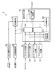
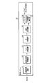
- FIG. 1 is a block diagram illustrating a transmission system and a reception system according to the first embodiment.
- FIG. 2 is a diagram showing a configuration of a TLV packet generated by the TLV multiplexing apparatus shown in FIG.
- FIG. 3 is a diagram illustrating the configuration of the slot according to the first embodiment.
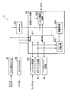
- FIG. 4 is a block diagram showing an example of a functional configuration of the transmission slotting apparatus shown in FIG.
- FIG. 5 is a diagram showing a slot configuration of a transmission main signal output from the slot information multiplexing unit shown in FIG. 4 to the transmission processing device.
- FIG. 6 is a flowchart showing processing when the data received by the selection unit shown in FIG. 4 is stored in the slot.
- FIG. 7 is a diagram illustrating a transmission main signal output from the selection unit illustrated in FIG.
- FIG. 8 is a diagram illustrating another example of the transmission main signal output from the selection unit illustrated in FIG. 4.
- FIG. 9 is a diagram illustrating another example of the transmission main signal output from the selection unit illustrated in FIG. 4.
- FIG. 10 is a block diagram showing a configuration of the receiving system shown in FIG.
- FIG. 11 is a block diagram showing a functional configuration of the transmission main signal receiving apparatus shown in FIG.
- FIG. 12 is a block diagram illustrating an example of a functional configuration of the transmission slotting apparatus according to the second embodiment.
- FIG. 13 is a flowchart showing a process when data received by the selection unit shown in FIG. 12 is stored in a slot.
- FIG. 1 is a block diagram showing a transmission system 10 and a reception system 20 according to the first embodiment.
- the transmission system 10 transmits a broadcast wave.
- the transmitted broadcast wave reaches the reception system 20 via a transmission path such as a broadcast network.
- the receiving system 20 receives broadcast waves.
- Transmission system 1 includes an encoder 11, an additional information generating device 12, an MMT (MPEG Media Transport) multiplexer 13, an IP (Internet Protocol) multiplexer 14, and a TLV (Type Length Value) multiplexer 15.
- An encoder 11 an additional information generating device 12
- an MMT MPEG Media Transport
- IP Internet Protocol
- TLV Type Length Value
- the encoder 11 receives a video / audio signal from, for example, a photographing apparatus such as a camera or a server.
- the encoder 11 encodes the received video / audio signal according to a preset method, thereby converting the video / audio signal into an encoded signal.
- the encoder 11 outputs the encoded signal to the MMT multiplexer 13.
- the additional information generation device 12 creates information about the billing / encryption of the program guide of the broadcast program and the video distribution content, and outputs the information to the MMT multiplexing device 13 as additional information.
- the transmission system 10 shown in FIG. 1 does not include an encryption unit (scrambler), but for example, an encryption unit is provided between the MMT multiplexer 13 and the IP multiplexer 14. .
- the MMT multiplexer 13 includes, for example, a CPU (Central Processing Unit), a memory used when the CPU executes processing, an FPGA (Field Programmable Gate Array) that executes predetermined processing according to control from the CPU, and the like. .
- the MMT multiplexer 13 executes a process on the encoded signal. That is, the MMT multiplexer 13 adds additional information to the encoded signal, and stores the encoded signal with the additional information in an MMTP (MPEG Media Transport Protocol) packet.
- the MMT multiplexer 13 outputs the MMTP packet to the IP multiplexer 14.
- the MMT multiplexer 13 may include an LSI (Large-Scale Integration) instead of the FPGA. Further, the MMT multiplexer 13 may execute predetermined processing by software.
- LSI Large-Scale Integration
- the IP multiplexer 14 includes, for example, a CPU, a memory used when the CPU executes processing, and an FPGA that executes predetermined processing according to control from the CPU.
- the IP multiplexer 14 executes a process on the MMTP packet. That is, the IP multiplexer 14 stores the MMTP packet in the IP packet.
- the IP multiplexer 14 outputs the IP packet to the TLV multiplexer 15.
- the IP multiplexer 14 may include an LSI instead of the FPGA. Further, the IP multiplexing device 14 may execute predetermined processing by software.
- the TLV multiplexing device 15 includes, for example, a CPU, a memory used when the CPU executes processing, and an FPGA that executes predetermined processing according to control from the CPU.
- the TLV multiplexing device 15 executes processing on the IP packet. That is, the TLV multiplexing device 15 generates a TLV packet based on the IP packet.
- FIG. 2 is a schematic diagram showing a configuration of a TLV packet generated by the TLV multiplexer 15.
- the TLV packet is composed of 2 bits “01”, 6 bits “111111”, 8 bits “packet type” for identifying the type of packet stored in the TLV, and subsequent data bytes It consists of a 16-bit “data length” in which the number is written and data in which the number of data bytes is indicated by the data length.
- the capacity of the TLV packet is a minimum of 4 bytes (2 bits + 6 bits + 8 bits + 16 bits + 0 bytes).
- the TLV multiplexing device 15 outputs the TLV packet to the transmission slotting device 16.
- the TLV multiplexer 15 may include an LSI instead of the FPGA. Further, the TLV multiplexer 15 may execute predetermined processing by software.
- the transmission slotting device includes 16, for example, a CPU, a memory used when the CPU executes processing, and an FPGA that executes predetermined processing according to control from the CPU.
- the transmission slotting device 16 executes processing on the TLV packet. That is, the transmission slotting device 16 generates the transmission main signal by storing the TLV packet in any of the slots constituting the transmission main signal.
- the transmission slotting device 16 outputs the generated transmission main signal to the transmission processing device 17.
- the transmission main signal is a signal generated in units of slots.
- the transmission mode setting for the transmission main signal is updated for each frame composed of 120 slots based on the setting information.
- the setting information includes information about transmission modes such as a modulation scheme and a coding rate for 120 slots in the transmission main signal.
- FIG. 3 is a schematic diagram showing a configuration example of a slot.
- the slot is a signal obtained by adding an error correction outer code and a stuff bit to the slot header and the main signal, and adding an error correction inner code to this signal.
- at least one of a TLV packet, an NTP packet, a TLV NULL packet, and a slot padding byte is stored in the main signal.
- FIG. 4 is a block diagram showing an example of the functional configuration of the transmission slotting apparatus 16 shown in FIG. 4, the slot number counter 161, the setting information receiving unit 162, the capacity calculating unit 163, the transmission slotting unit 164, the TLV packet receiving unit 165, the NTP (Network (Time Protocol) packet generating unit 166, and the slot padding byte generating unit 167.
- the functions of the TLV NULL packet generation unit 168 are realized by causing the CPU to execute predetermined processing by the CPU.
- the transmission slotting device 16 may include the LSI instead of the FPGA to realize the function shown in FIG. Also, the transmission slotting device 16 may realize the function shown in FIG. 4 by software.
- the slot number counter 161 sets the count value to 1, and then restarts counting using the transmission clock.
- the slot number counter 161 increments the slot number by 1 and counts the number of transmission clocks of the next slot. As a result, the count starts with the start of the frame.
- the slot number counter 161 outputs the count value to the capacity calculation unit 163 and the selection unit 1641.
- the setting information receiving unit 162 receives setting information for setting the transmission mode for each frame of the transmission main signal.
- the setting information receiving unit 162 outputs the setting information to the capacity calculating unit 163 and the transmission slotting unit 164.
- the coding rate included in the setting information can be set, for example, as shown by the coding rate in FIG. 3, and the number of main signal bits varies according to the variation of the coding rate.
- the modulation methods included in the setting information include, for example, a 16-value amplitude phase modulation method (16APSK), an 8-phase phase modulation method (8PSK), a 4-phase phase modulation method (QPSK), and a ⁇ -shift two-phase modulation method. ( ⁇ / 2 shift BPSK) or the like.
- 16APSK when the slot unit is 5, the number of valid slots is 4, and the number of invalid slots is 1.
- 8PSK when the slot unit is 5, the number of valid slots is 3, and the number of invalid slots is 2.
- QPSK when the slot unit is 5, the number of valid slots is 2, and the number of invalid slots is 3.
- the number of valid slots is 1, and the number of invalid slots is 4.
- the total number of main signal bits for every five slots is determined by the combination of the modulation method and the coding rate included in the setting information.
- the combination of the modulation scheme and coding rate included in the setting information is not limited to one type. There may be two or more combinations of modulation schemes and coding rates included in the setting information. When there are a plurality of combinations, the transmission modes are assigned to the slots in ascending order from slot number 1 in the order of the highest multi-level modulation scheme and the same modulation scheme, starting from the highest coding rate.
- the capacity calculation unit 163 receives the count value output from the slot number counter 161 and the setting information output from the setting information receiving unit 162.
- the capacity calculation unit 163 receives the first count value in the frame, that is, “1”, the number of main signal bits determined by the coding rate, and the ratio between the effective slot and the invalid slot determined from the modulation scheme Based on the above, the effective main signal capacity for the frame is calculated as the frame main signal capacity.
- the capacity calculating unit 163 calculates the effective main signal capacity in the slot indicated by the number indicated by the count value as the slot main signal capacity. After calculating the frame main signal capacity and the slot main signal capacity, the capacity calculation unit 163 outputs information about the calculated frame main signal capacity and information about the calculated slot main signal capacity to the transmission slotting unit 164.
- the capacity calculation unit 163 calculates a pseudo frame main signal capacity for each combination.
- the capacity calculation unit 163 uses the pseudo slot main signal capacity at the slot start position allocated according to the combination of the modulation scheme and the coding rate included in the setting information.
- the TLV packet receiving unit 165 receives the TLV packet output from the TLV multiplexing device 15.
- the TLV packet receiving unit 165 includes a buffer (not shown), and holds the received TLV packet in the buffer.
- the TLV packet receiving unit 165 outputs the held TLV packet to the transmission slotting unit 164 in response to an instruction from the transmission slotting unit 164.
- the NTP packet generator 166 generates an NTP format IP packet.
- the NTP packet generation unit 166 generates an NTP packet by storing an IP packet including the NTP format in the TLV packet.
- the ARIB STD-B44 version 2.0 stipulates that the NTP packet is placed at the head of the first slot in the frame among the slots assigned for each TLV stream ID. This is for suppressing delay variation of the NTP packet. Note that the NTP packet is not necessarily included for each frame. Further, when there are two or more combinations of modulation schemes and coding rates in the same TLV stream ID, an NTP packet may be arranged at the head of the first slot of the slot having the strongest error tolerance.
- the NTP packet generation unit 166 receives a notification of the timing for inserting the NTP packet from the transmission slotting unit 164, and outputs an NTP packet including the NTP time (system time) at that time to the transmission slotting unit 164. Note that the NTP packet generation unit 166 may correct the NTP time by adding or subtracting an offset set from the outside.
- the slot padding byte generation unit 167 generates a data string set in advance as a slot padding byte in response to an instruction from the transmission slotting unit 164.
- the first byte of the TLV packet is “0x7f” as described in FIG.
- the slot padding byte generation unit 167 generates a data string different from “0x7f”, for example, “0x7e” as a slot padding byte.
- the slot padding byte is not limited to “0x7e” and may be other than “0x7f”.
- the slot padding byte generation unit 167 sets the slot padding byte when the remaining capacity of the last effective slot in the transmission main signal is 3 bytes to “0x7e”, and the slot padding byte when the remaining capacity is 2 bytes. “0x7d” may be set, the slot padding byte when the remaining capacity is 1 byte may be “0x7c”, and the lower 2 bits may represent the remaining capacity.
- the slot padding byte generation unit 167 outputs the generated slot padding byte to the transmission slotting unit 164.
- the TLV NULL packet generation unit 168 receives the instruction from the transmission slotting unit 164, and generates a TLV NULL packet with the instructed capacity.
- the TLV NULL packet generation unit 168 outputs the generated TLV NULL packet to the transmission slotting unit 164.
- the TLV NULL packet generated by the TLV NULL packet generation unit 168 may be two or more packets. For example, if the indicated capacity exceeds a predetermined capacity, for example, 1500 bytes, the TLV NULL packet generation unit 168 generates a plurality of TLV NULL packets with the maximum capacity being 1500 bytes.
- the transmission slotting unit 164 includes a selection unit 1641, a TLV byte number extraction unit 1642, a remaining amount calculation unit 1643, and a slot information multiplexing unit 1644.
- the TLV byte number extraction unit 1642 receives the TLV packet output from the TLV packet reception unit 165 or the NTP packet output from the NTP packet generation unit 166.
- the TLV byte number extraction unit 1642 extracts the data length shown in FIG. 2 from the received TLV packet or NTP packet, and acquires the data capacity included in the TLV packet or NTP packet.
- the TLV byte number extraction unit 1642 outputs information about the acquired data capacity to the remaining amount calculation unit 1643.
- the remaining amount calculation unit 1643 outputs information about the frame main signal capacity output from the capacity calculation unit 163, information about the slot main signal capacity output from the capacity calculation unit 163, and the TLV byte number extraction unit 1642. Receive information about the data capacity.
- the remaining amount calculator 1643 calculates the remaining frame capacity by sequentially subtracting the data capacity from the frame main signal capacity.
- the remaining amount calculation unit 1643 outputs the calculated remaining frame capacity to the selection unit 1641.
- the remaining amount calculation unit 1643 calculates the remaining slot capacity by sequentially subtracting the data capacity from the frame main signal capacity.
- the remaining amount calculation unit 1643 outputs the calculated remaining slot capacity to the selection unit 1641.
- the selection unit 1641 stores the TLV packet, the NTP packet, or the TLV NULL packet in the slot indicated by the number indicated by the count value output from the slot number counter 161.
- the selection unit 1641 When the selection unit 1641 stores a TLV packet, an NTP packet, or a TLV NULL packet in the slot, the selection unit 1641 subtracts the stored data capacity from the remaining slot capacity output from the remaining capacity calculation unit 1643 to obtain the current remaining slot capacity. Is calculated. When the selection unit 1641 stores the TLV packet, the NTP packet, or the TLV NULL packet in the slot, the selection unit 1641 subtracts the stored data capacity from the remaining frame capacity output from the remaining amount calculation unit 1643, thereby obtaining the current frame. Calculate the remaining capacity.
- the selection unit 1641 stores the TLV packet, NTP packet, or TLV NULL packet in the slot, and if the remaining slot capacity of the last valid slot in the frame is less than 4 bytes, the slot padding to the slot padding byte generation unit 167 Output byte request instructions. At this time, the selection unit 1641 may request the slot padding byte generation unit 167 for the same slot padding bytes, for example, “0x7e” for a plurality of bytes.
- the selection unit 1641 requests “0x7e” for 3 bytes when the remaining slot capacity is 3 bytes, and requests “0x7d” for 2 bytes when the remaining slot capacity is 2 bytes. When 1 is 1 byte, “0x7c” may be requested for 1 byte.
- the request for slot padding bytes by the selection unit 1641 is not limited to the above, and various modes can be assumed. For example, the selection unit 1641 requests “0x7e”, “0x7d”, and “0x7c” when the remaining slot capacity is 3 bytes, and “0x7d” and “0x7c” when the remaining slot capacity is 2 bytes. If the remaining slot capacity is 1 byte, “0x7c” may be requested.
- the selection unit 1641 Whether the selection unit 1641 needs to store the NTP packet at the head of the slot indicated by the number indicated by the count value output from the slot number counter 161 based on the setting information output from the setting information receiving unit 162 Determine whether. If it is determined that it is necessary, the selection unit 1641 issues an NTP packet request instruction to the NTP packet generation unit 166. The selection unit 1641 stores the NTP packet output from the NTP packet generation unit 166 in the slot.
- the selection unit 1641 instructs the TLV NULL packet generation unit 168 to generate a TLV NULL packet having a capacity corresponding to the remaining frame capacity and the remaining slot capacity. Upon receiving the TLV NULL packet output from the TLV NULL packet generation unit 168, the selection unit 1641 stores the received TLV NULL packet in the slot.
- the selection unit 1641 outputs the slot storing the data to the slot information multiplexing unit 1644.
- the slot information multiplexing unit 1644 is information about the frame main signal capacity output from the capacity calculation unit 163, information about the slot main signal capacity output from the capacity calculation unit 163, and setting information output from the setting information receiving unit 162. And the slot output from the selection part 1641 is received.
- the slot information multiplexing unit 1644 creates slot information for the received slot based on the received frame main signal capacity, slot main signal capacity, and setting information.
- the slot information includes a synchronization signal, signal point arrangement information, and TMCC information.
- the signal point arrangement information indicates the start position of the first packet included in each slot and the end position of the last packet included in each slot.
- the TMCC information includes information about a transmission mode including a coding rate and a modulation scheme, information about a TLV stream ID, and the like.
- FIG. 5 is a schematic diagram showing a slot configuration of a transmission main signal output from the slot information multiplexing unit 1644 to the transmission processing device 17.
- the transmission processing device 17 includes, for example, a CPU, a memory used when the CPU executes processing, and an FPGA that executes predetermined processing according to control from the CPU.
- the transmission processing device 17 executes processing on the transmission main signal. That is, the transmission processing device 17 receives the transmission main signal output from the transmission slotting device 16 and modulates the received transmission main signal with the modulation scheme assigned to each slot.
- the transmission processing device 17 performs predetermined transmission processing on the modulated signal and generates a broadcast wave.
- the transmission processing device 17 transmits a broadcast wave.
- the transmission processing device 17 may include an LSI instead of the FPGA. Further, the transmission processing device 17 may execute predetermined processing by software.
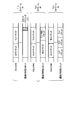
- FIG. 6 is a flowchart illustrating an example of processing when data received by the selection unit 1641 illustrated in FIG. 4 is stored in a slot. Note that FIG. 6 illustrates an example in which there is one transmission mode in a frame, that is, one combination of modulation scheme and coding rate included in the setting information.
- the selection unit 1641 receives a count value from the slot number counter 161 (step S61). The selection unit 1641 determines whether or not the received count value is 1 (step S62). When the received count value is 1 (Yes in step S62), the selection unit 1641 recognizes that a new frame has started (step S63). When the received count value is not 1 (No in Step S62), the selection unit 1641 determines whether to store the NTP packet in the slot indicated by the number indicated by the count value (Step S64).
- the selection unit 1641 stores the NTP packet at the head of the current slot (Step S65).
- the selection unit 1641 determines whether or not the current slot is the last valid slot in the current frame (step S66).
- the selection unit 1641 updates the current slot remaining capacity by subtracting the capacity of the stored data from the remaining slot capacity output from the remaining amount calculating unit 1643. Further, when the selection unit 1641 stores data in the current slot, the selection unit 1641 updates the current frame remaining capacity by subtracting the stored data capacity from the frame remaining capacity output from the remaining amount calculating unit 1643 (step S41). S67).
- the selection unit 1641 determines whether or not the remaining slot capacity in the current slot is 0 (step S68). When the slot remaining capacity in the current slot is 0 (Yes in step S68), the selection unit 1641 determines whether the frame remaining capacity in the current frame is 0 (step S69). If the remaining slot capacity in the current slot is not 0 (No in step S68), the selection unit 1641 moves the process to step S66.
- step S69 If the remaining frame capacity in the current frame is 0 (Yes in step S69), the selection unit 1641 waits until the next frame is started (step S610). If the remaining frame capacity in the current frame is not 0 (No in step S69), the selection unit 1641 moves the process to step S61.
- step S66 when the current slot is the last valid slot in the current frame (Yes in step S66), the selection unit 1641 determines whether or not the remaining slot capacity of the current slot is less than 4 bytes (step S611). ). If the current slot is not the last valid slot in the current frame (No in step S66), the selection unit 1641 determines whether there is a TLV packet to be stored in the current slot (step S612).
- step S611 if the remaining slot capacity of the current slot is less than 4 bytes (Yes in step S611), the selection unit 1641 assigns the slot padding bytes output from the slot padding byte generation unit 167 to an area of less than 4 bytes. Store (step S613), and the process proceeds to step S610.
- step S612 when there is a TLV packet to be stored in the current slot (Yes in step S612), the selection unit 1641 determines whether or not the TLV packet cannot be stored in the current frame, that is, stores the TLV packet in the current slot. Then, it is determined whether or not the remaining frame capacity of the current frame is less than 0 (step S614). When there is no TLV packet to be stored in the current slot (No in step S612), the selection unit 1641 stores the TLV NULL packet output from the TLV NULL packet generation unit 168 in the current slot (step S615), and performs processing. Control goes to step S67.
- the selection unit 1641 concatenates the current slot and the last valid slot in the current frame.
- the TLV NULL packet is stored instead of this TLV packet (step S616).
- the selection unit 1641 determines whether the remaining slot capacity of the current slot is less than 0 when the TLV packet is stored in the current slot. It is determined whether or not (step S617).
- the selection unit 1641 selects the first TLV packet having a capacity that can be stored in the current slot, It is divided into other second TLV packets (step S618).
- the selection unit 1641 stores the divided first TLV packet in the current slot (step S619), and the process proceeds to step S67.
- the selection unit 1641 stores the TLV packet in the current slot (step S620), and the process proceeds to step S67. Transition.
- a slot group as illustrated in FIG. 7 is output to the slot information multiplexing unit 1644.
- slot padding bytes are stored at the end of the last valid slot.
- the selection unit 1641 can perform the same operation even when there are two or more transmission modes in a frame.
- the capacity calculation unit 163 calculates the effective main signal capacity for each transmission mode as the frame main signal capacity according to the setting information.
- the remaining amount calculation unit 1643 calculates the frame remaining capacity for each transmission mode by subtracting the data capacity output from the TLV byte number extraction unit 1642 from the frame main signal capacity calculated for each transmission mode.
- the selection unit 1641 stores the TLV packet in the slot while referring to the remaining frame capacity and the remaining slot capacity in accordance with the transmission mode assignment to the slot indicated in the setting information.
- FIG. 8 is a diagram showing a slot configuration when there is one TLV stream and two transmission modes.
- the multi-level number of the transmission mode modulation method assigned to slots # 1 to # 60 is larger than the multi-level number of the transmission mode modulation method assigned to slots # 61 to # 120.
- the NTP packet is placed at the head of slot # 61.
- slot padding bytes are stored at the end of the last valid slot in each transmission mode.
- FIG. 9 is a diagram showing a slot configuration when there are three TLV streams and three transmission modes.
- the NTP packet for the transmission mode assigned to slots # 1 to # 40 is stored at the head of slot # 1
- the NTP packet for the transmission mode assigned to slots # 41 to # 80 is the head of slot # 41.
- the NTP packet for the transmission mode assigned to slots # 81 to # 120 is stored at the head of slot # 81.
- slot padding bytes are stored at the end of the last valid slot in the transmission mode assigned to slots # 1 to # 40.
- the transmission system 10 calculates the frame main signal capacity and the slot main signal capacity by the capacity calculation unit 163 of the transmission slotting device 16.
- the remaining amount calculating unit 1643 calculates the remaining frame capacity by subtracting the data capacity of the TLV packet from the frame main signal capacity, and subtracts the data capacity of the TLV packet from the slot main signal capacity, thereby calculating the remaining slot capacity. calculate.
- the selection unit 1641 stores slot padding bytes in the remaining area.
- the transmission system 10 according to the first embodiment allows the frame remaining capacity in the last valid slot in the frame to be less than 4 bytes by storing the TLV packet in the valid slot. Data can be stored up to the end of the last valid slot.
- the broadcast wave is transmitted. It can be transmitted normally.
- the 3-byte area remaining in the last valid slot in the first frame and the first slot of the second frame following the first frame are concatenated, and a TLV NULL packet is stored in the concatenated slot.
- Countermeasures can be considered. However, when storing the NTP packet, the position is defined as the head in the first slot, so this countermeasure does not extend to the function achieved by the transmission system according to the first embodiment.
- the slot padding byte generation unit 167 generates a plurality of types of slot padding bytes corresponding to the remaining capacity.
- the selection unit 1641 stores slot padding bytes corresponding to the remaining capacity.
- FIG. 10 is a block diagram showing a configuration of the receiving system 20 shown in FIG.
- the reception system 20 shown in FIG. 10 includes a reception processing device 21, a transmission main signal reception device 22, a TLV separation device 23, an IP separation device 24, an MMT separation device 25, a decoder 26, and an additional information interpretation unit 27.
- the reception processing device 21 receives incoming broadcast waves via a transmission line such as a broadcast network.
- the reception processing device 21 performs predetermined reception processing on the received broadcast wave and performs demodulation processing using a demodulation method corresponding to the modulation method assigned to each slot, thereby transmitting the broadcast wave to Convert to signal.
- the reception processing device 21 outputs the transmission main signal to the transmission main signal receiving device 22.
- FIG. 11 is a block diagram showing an example of a functional configuration of the transmission main signal receiving device 22 shown in FIG.
- the functions of the data separation unit 221, the NTP time reproduction unit 222, the slot information interpretation unit 223, and the slot padding byte removal unit 224 shown in FIG. 10 are realized by causing the CPU to execute predetermined processing by the CPU.
- the transmission main signal receiving device 22 may include an LSI instead of the FPGA to realize the function shown in FIG. Further, the transmission main signal receiving device 22 may realize the function shown in FIG. 11 by software.
- the data separator 221 receives the transmission main signal output from the reception processing device 21.
- the data separator 221 separates the slot information added to the slot from the slot included in the received transmission main signal.
- the data separation unit 221 outputs the separated slot information to the slot information interpretation unit 223.
- the data separation unit 221 refers to the slot header of the slot included in the received transmission main signal and extracts the main signal from the slot.
- the data separator 221 outputs the NTP packet included in the main signal to the NTP time reproducing unit 222. Further, the data separation unit 221 outputs data other than the NTP packet included in the main signal to the slot padding byte removal unit 224.
- the NTP time reproduction unit 222 generates NTP time information based on the NTP packet output from the data separation unit 221.
- the NTP time reproduction unit 222 adjusts the internally counted clock so that the generated NTP time information and the internally counted time information are synchronized, and outputs the internally counted time information to the subsequent apparatus. For example, when the NTP time information is received, the clock is compared with the value of the time information counted internally. If the time information counted internally is advanced, the clock is lowered, and if it is delayed, the clock is adjusted. This is done by controlling the oscillation frequency of VCXO (Voltage-Controlled-Xtal-Oscillator).
- VCXO Voltage-Controlled-Xtal-Oscillator
- the slot information interpretation unit 223 receives the slot information output from the data separation unit 221.
- the slot information interpretation unit 223 interprets signal point arrangement information and TMCC information included in the slot information from the received slot information.
- the slot information interpretation unit 223 outputs the signal point arrangement information and the TMCC information to the slot padding byte removal unit 224.
- the slot padding byte removal unit 224 stores in advance a data string to be slot padding bytes, for example, “0x7e”.
- the slot padding byte removal unit 224 receives the signal point arrangement information and the TMCC information output from the slot information interpretation unit 223.
- the slot padding byte removal unit 224 grasps the transmission mode of the transmission main signal, the position of the end of the last packet in the last valid slot in the frame, and the like based on the received signal point arrangement information and TMCC information.
- the slot padding byte removal unit 224 receives the data output from the data separation unit 221, it determines whether or not the stored data string exists at the end position.
- the slot padding byte removing unit 224 removes the slot padding bytes arranged for a maximum of 3 bytes from the end position in the received data.
- the slot padding byte removing unit 224 outputs the data after removing the slot padding bytes, that is, the TLV packet or the TLV NULL packet, to the TLV separation device.
- the information stored in the slot padding byte removal unit 224 is not limited to a data string. For example, if the slot contains “0x7e”, the slot padding byte removal unit 224 is unnecessary data including 3 bytes including “0x7e”, and if the slot contains “0x7d”, the slot padding byte removal unit 224 sets “0x7d”. If 2 bytes including the data are unnecessary and “0x7c” is included in the slot, information indicating that 1 byte is unnecessary including “0x7c” may be stored in advance. At this time, the slot padding byte removal unit 224 removes unnecessary data included in the data according to the slot padding bytes included in the data output from the data separation unit 221.
- the TLV separator 23 receives the TLV packet and the TLV NULL packet output from the transmission main signal receiver 22.
- the TLV separator 23 extracts an IP packet from the received TLV packet.
- the TLV separator 23 outputs the extracted IP packet to the IP separator 24.
- the IP separator 24 receives the IP packet output from the TLV separator 23.
- the IP separator 24 extracts the MMTP packet from the received IP packet.
- the IP separator 24 outputs the extracted MMTP packet to the MMT separator 25.
- the MMT separator 25 receives the MMTP packet output from the IP separator 24.
- the MMT separation device 25 extracts the encoded signal and the additional information from the received MMTP packet.
- the MMT separation device 25 outputs the extracted encoded signal to the decoder 26, and outputs the extracted additional information to the additional information interpretation unit 27.
- the decoder 26 receives the encoded signal output from the MMT separator 25 and decodes it according to a preset method, thereby converting the encoded signal into a video / audio signal.
- the decoder 26 outputs the video / audio signal to a subsequent device.
- the additional information interpretation unit 27 receives additional information output from the MMT separation device 25.
- the additional information interpretation unit 27 outputs information read from the received additional information to a subsequent apparatus.
- the transmission main signal receiver 22 extracts the main signal from the slot.
- the transmission main signal receiving device 22 stores in advance a data string to be slot padding bytes. Then, when the main signal includes slot padding bytes, the transmission main signal receiver 22 removes the slot padding bytes from the main signal. As a result, the transmission main signal receiving device 22 can normally extract the TLV packet from the transmission main signal even when the slot constituting the transmission main signal includes slot padding bytes.
- the transmission main signal receiving device 22 even if the transmission main signal transmitted from the transmission system 10 includes a slot padding byte, the broadcast wave in the reception system 20 is transmitted. Normal reception can be realized.
- the transmission slotting device 16 stores slot padding bytes in an empty area when the remaining slot capacity of the last valid slot in the transmission main signal is less than 4 bytes.
- the transmission slotting device 18 stores a packet in a slot so that the remaining slot capacity of the last effective slot in the transmission main signal does not become less than 4 bytes.
- FIG. 12 is a block diagram illustrating an example of a functional configuration of the transmission slotting apparatus 18 according to the second embodiment.
- the functions of the slot number counter 161, the setting information receiving unit 162, the capacity calculating unit 163, the transmission slotting unit 181, the TLV packet receiving unit 165, the NTP packet generating unit 166, and the TLV NULL packet generating unit 168 shown in FIG. Is realized by causing the FPGA to execute predetermined processing.
- the transmission slotting device 18 may be provided with an LSI instead of the FPGA to realize the function shown in FIG. Further, the transmission slotting device 18 may realize the function shown in FIG. 12 by software.
- the transmission slotting unit 181 includes a selecting unit 1811, a TLV byte number extracting unit 1642, a remaining amount calculating unit 1643, and a slot information multiplexing unit 1644.
- the selection unit 1811 stores the TLV packet, the NTP packet, or the TLV NULL packet in the slot indicated by the number indicated by the count value output from the slot number counter 161.
- the selection unit 1811 When the selection unit 1811 stores the TLV packet, the NTP packet, or the TLV NULL packet in the slot, the selection unit 1811 subtracts the capacity of the stored data from the remaining slot capacity output from the remaining amount calculation unit 1643 to thereby obtain the current remaining slot capacity. Is calculated. When the selection unit 1811 stores the TLV packet, the NTP packet, or the TLV NULL packet in the slot, the selection unit 1811 subtracts the stored data capacity from the remaining frame capacity output from the remaining amount calculation unit 1643, thereby obtaining the current frame. Calculate the remaining capacity.
- the selection unit 1811 Whether the selection unit 1811 needs to store the NTP packet at the head of the slot indicated by the number indicated by the count value output from the slot number counter 161 based on the setting information output from the setting information receiving unit 162 Determine whether.
- the selection unit 1811 issues an NTP packet request instruction to the NTP packet generation unit 166.
- the selection unit 1811 stores the NTP packet output from the NTP packet generation unit 166 in the slot.
- the selection unit 1811 instructs the TLV NULL packet generation unit 168 to generate a TLV NULL packet having a capacity corresponding to the remaining frame capacity and the remaining slot capacity. Upon receiving the TLV NULL packet output from the TLV NULL packet generation unit 168, the selection unit 1811 stores the received TLV NULL packet in the slot.
- the selection unit 1811 outputs the slot storing the data to the slot information multiplexing unit 1644.
- FIG. 13 is a flowchart illustrating processing when the selection unit 1811 stores a packet in a slot.
- FIG. 13 a case where there is one transmission mode in a frame will be described as an example.
- the selection unit 1811 receives a count value from the slot number counter 161 (step S131). The selection unit 1811 determines whether or not the received count value is 1 (step S132). When the received count value is 1 (Yes in step S132), the selection unit 1811 recognizes that a new frame has started (step S133). When the received count value is not 1 (No in Step S132), the selection unit 1811 determines whether or not to store the NTP packet in the slot indicated by the number indicated by the count value (Step S134).
- the selection unit 1811 stores the NTP packet at the head of the current slot (step S135).
- the selection unit 1811 determines whether there is a TLV packet to be stored in the current slot (step S136).
- the selection unit 1811 updates the current slot remaining capacity by subtracting the stored data capacity from the remaining slot capacity output from the remaining capacity calculating unit 1643.
- the selection unit 1811 updates the current frame remaining capacity by subtracting the capacity of the stored data from the remaining frame capacity output from the remaining amount calculation unit 1643 ( Step S137).
- the selection unit 1811 determines whether or not the remaining slot capacity in the current slot is 0 (step S138). When the slot remaining capacity in the current slot is 0 (Yes in step S138), the selection unit 1811 determines whether the frame remaining capacity in the current frame is 0 (step S139). If the remaining slot capacity in the current slot is not 0 (Yes in step S138), the selection unit 1811 moves the process to step S136.
- step S139 If the remaining frame capacity in the current frame is 0 (Yes in step S139), the selection unit 1811 waits until the next frame is started (step S1310). If the remaining frame capacity in the current frame is not 0 (No in step S139), the selection unit 1811 moves the process to step S131.
- step S136 when there is a TLV packet to be stored in the current slot (Yes in step S136), the selection unit 1811 determines whether the remaining frame capacity of the current frame becomes less than 4 bytes when the TLV packet is stored in the current slot. Is determined (step S1311). When there is no TLV packet to be stored in the current slot (No in step S136), the selection unit 1811 stores the TLV NULL packet output from the TLV NULL packet generation unit 168 in the current slot (step S1312), and performs processing. Control goes to step S137.
- the selection unit 1811 concatenates the current slot and the last valid slot in the current frame.
- the TLV NULL packet is stored in the concatenated slot (step S1313).
- the selection unit 1811 sets the remaining slot capacity of the current slot to 0 when the TLV packet is stored in the current slot. It is determined whether it is below (step S1314).
- the selection unit 1811 selects the TLV packet as a first TLV packet having a capacity that can be stored in the current slot, It is divided into other second TLV packets (step S1315).
- the selection unit 1811 stores the divided first TLV packet in the current slot (step S1316), and the process proceeds to step S137. If the remaining slot capacity of the current slot becomes 0 or more when the TLV packet is stored in the current slot (No in step S1314), the selection unit 1811 stores the TLV packet in the current slot (step S1317), and the process proceeds to step S137. Transition.
- the selection unit 1811 can perform the same operation even when there are two or more transmission modes in a frame.
- the transmission system 10 calculates the frame main signal capacity and the slot main signal capacity by the capacity calculation unit 163 of the transmission slotting device 18.
- the remaining amount calculating unit 1643 calculates the remaining frame capacity by subtracting the data capacity of the TLV packet from the frame main signal capacity, and subtracts the data capacity of the TLV packet from the slot main signal capacity, thereby calculating the remaining slot capacity. calculate. If the remaining frame capacity of the current frame becomes less than 4 bytes when the TLV packet is stored in the slot, the selection unit 1811 stores the TLV NULL packet until the end of the slot without storing the TLV packet in the slot. ing. As a result, the transmission system 10 according to the second embodiment can store the TLV packet and the TLV NULL packet up to the end of the last valid slot in the frame.
- the transmission system 10 according to the second embodiment it is possible to avoid that the remaining capacity in the last effective slot in the frame is less than 4 bytes.
- the transmission slotting devices 16 and 18 store the TLV packet in the main signal of the slot has been described as an example.
- the TLV packet is shown as an example of a variable length packet including information indicating the data type and information indicating the number of data bytes.
- Examples of the variable-length packet including information indicating the data type and information indicating the number of data bytes include a GSE (Generic Stream Encapsulated) packet in addition to the TLV packet.
- the TLV multiplexer 15 may be described as a variable length packet multiplexer.
- the minimum number of bytes that a TLV packet can take is 4 bytes, and the selection units 1641 and 1811 determine whether or not the remaining capacity of the last valid slot is less than 4 bytes.
- the number of bytes used as a criterion for determination by the selection units 1641 and 1811 is not limited to less than 4 bytes.
- the minimum number of bytes that a variable length packet can take is not limited to 4 bytes.
- the selection units 1641 and 1811 perform processing according to whether or not the remaining capacity of the last valid slot is less than 2 bytes. May be.
Landscapes
- Engineering & Computer Science (AREA)
- Signal Processing (AREA)
- Computer Networks & Wireless Communication (AREA)
- Multimedia (AREA)
- Computer Hardware Design (AREA)
- Time-Division Multiplex Systems (AREA)
Abstract
送信システムは、TLV多重化装置と、伝送スロット化装置とを具備する。伝送スロット化装置は、容量算出部、抽出部、残容量算出部、選択部及びスロット情報多重部を備える。容量算出部は、設定情報を受信し、設定情報に基づいて1フレームの伝送主信号に含めることが可能なデータ容量を算出する。抽出部は、TLVパケットからバイト数を抽出する。残容量算出部は、データ容量とバイト数とに基づき、伝送主信号の残容量を算出する。選択部は、TLVパケットをスロットに格納することで残容量が4バイト未満となる場合、残された領域に所定のデータ列を格納する。スロット情報多重部は、選択部からのスロットにスロット情報を多重する。
Description
本発明の実施形態は、TLV(Type Length Value)パケットをスロットに格納することで伝送主信号を生成し、この伝送主信号に基づく放送波を送信する送信システム、この送信システムで用いられる伝送スロット化装置、この送信システムから送信される放送波を受信する受信装置、及び、伝送スロット化装置で用いられる伝送スロット作成方法に関する。
現在の放送システムでは、MPEG-2 TS(Moving Picture Experts Group-2 Transport Stream)方式、及び、RTP(Real-time Transport Stream)方式のメディアトランスポート方式が広く用いられている。これらの方式では、放送と通信とを協調させようとすると、様々な限界がある。そこで、MPEGを利用して多様なネットワークを用いることを想定した新たなメディアトランスポート方式であるMMT(MPEG Media Transport)が提案されている。
MMTを用いた送信システムは、MMTP(MPEG Media Transport Protocol)/UDP(User Datagram Protocol)/IP(Internet Protocol)パケットをTLVパケット化する。送信システムは、TLVパケットをスロットに格納して伝送主信号を生成する。伝送主信号は、スロットを単位として生成される信号であり、例えば、120のスロットで構成されるフレーム毎に伝送制御の設定が更新される。送信システムは、伝送主信号に対して変調処理等の処理を施し、放送波として送信する。
ところで、送信システムがTLVパケットをスロットに格納することで伝送主信号を生成する場合、伝送主信号におけるフレーム中の最後の有効スロットの残容量が4バイト未満となることが考えられる。しかしながら、TLVパケットの最小容量は4バイトであるため、残容量が4バイト未満である場合、このスロットにTLVパケットを格納することは不可能である。
「デジタル放送における映像符号化、音声符号化及び多重化方式」、ARIB STD-B32 3.1版
「高度広帯域衛星デジタル放送の伝送方式」、ARIB STD-B44 2.0版
以上のように、残容量が4バイト未満である場合、このスロットにTLVパケットを格納することは不可能であるため、送信システムからの放送波の送信に支障をきたすおそれがある。
そこで目的は、伝送主信号における最後の有効スロットの残容量が、有効スロットにTLVパケットを格納することにより4バイト未満となっても放送波を正常に送信可能な送信システム、この送信システムで用いられる伝送スロット化装置、この送信システムから送信される放送波を受信する受信装置、及び、伝送スロット化装置で用いられる伝送スロット作成方法を提供することにある。また、伝送主信号における最後の有効スロットの残容量が4バイト未満となることを回避可能な送信システム、この送信システムで用いられる伝送スロット化装置、及び、この伝送スロット化装置で用いられる伝送スロット作成方法を提供することにある。
実施形態によれば、送信システムは、データの種別を示す情報と前記データのバイト数を示す情報とを含む可変長パケットを生成する可変長パケット多重化装置と、伝送主信号を構成する複数のスロットのいずれかに前記可変長パケットを格納する伝送スロット化装置とを具備する。伝送スロット化装置は、容量算出部、抽出部、残容量算出部、選択部及びスロット情報多重部を備える。容量算出部は、前記伝送主信号についての1フレーム分の設定情報を受信し、前記設定情報に基づいて1フレームの前記伝送主信号に含めることが可能なデータ容量を算出する。抽出部は、前記可変長パケットのバイト数を抽出する。残容量算出部は、前記容量算出部が算出する前記データ容量と前記抽出部が抽出する前記バイト数とに基づき、前記伝送主信号の残容量を算出する。選択部は、前記可変長パケットをスロットのいずれかに格納した前記伝送主信号の残容量が、可変長パケットが取り得る最小バイト数未満である場合、前記スロット中の残された領域に予め設定されるデータ列を格納し、前記データ列を格納したスロットを出力する。スロット情報多重部は、前記選択部が出力するスロットにスロット情報を多重する。
以下、実施の形態について、図面を参照して説明する。
(第1の実施形態)
図1は、第1の実施形態に係る送信システム10と受信システム20とを示すブロック図である。送信システム10は、放送波を送信する。送信される放送波は、放送ネットワーク等の伝送路を介して受信システム20へ到達する。受信システム20は、放送波を受信する。
図1は、第1の実施形態に係る送信システム10と受信システム20とを示すブロック図である。送信システム10は、放送波を送信する。送信される放送波は、放送ネットワーク等の伝送路を介して受信システム20へ到達する。受信システム20は、放送波を受信する。
(送信システム)
図1に示される送信システム10は、エンコーダ11、付加情報生成装置12、MMT(MPEG Media Transport)多重化装置13、IP(Internet Protocol)多重化装置14、TLV(Type Length Value)多重化装置15、伝送スロット化装置16及び送信処理装置17を備える。
図1に示される送信システム10は、エンコーダ11、付加情報生成装置12、MMT(MPEG Media Transport)多重化装置13、IP(Internet Protocol)多重化装置14、TLV(Type Length Value)多重化装置15、伝送スロット化装置16及び送信処理装置17を備える。
エンコーダ11は、例えば、カメラ等の撮影装置、又は、サーバ等から、映像・音声信号を受信する。エンコーダ11は、受信した映像・音声信号を予め設定される方式に従って符号化することで、映像・音声信号を符号化信号へ変換する。エンコーダ11は、符号化信号をMMT多重化装置13へ出力する。
付加情報生成装置12は、放送番組の番組表、及び、映像配信コンテンツの課金・暗号化等についての情報を作成し、付加情報としてMMT多重化装置13へ出力する。なお、図1に示される送信システム10には、暗号化部(スクランブラ)は記載されていないが、例えば、MMT多重化装置13とIP多重化装置14との間に暗号化部が設けられる。
MMT多重化装置13は、例えば、CPU(Central Processing Unit)、CPUが処理を実行する際に用いるメモリ、及び、CPUからの制御に従って所定の処理を実行するFPGA(Field Programmable Gate Array)等を備える。CPUがFPGAに所定の処理を実行させることで、MMT多重化装置13は、符号化信号に対する処理を実行する。すなわち、MMT多重化装置13は、符号化信号に付加情報を付加し、付加情報を付加した符号化信号をMMTP(MPEG Media Transport Protocol)パケットに格納する。MMT多重化装置13は、MMTPパケットをIP多重化装置14へ出力する。
なお、MMT多重化装置13は、FPGAの代わりにLSI(Large-Scale Integration)を備えるようにしても構わない。また、MMT多重化装置13は、ソフトウェアにより所定の処理を実行するようにしても構わない。
IP多重化装置14は、例えば、CPU、CPUが処理を実行する際に用いるメモリ、及び、CPUからの制御に従って所定の処理を実行するFPGA等を備える。CPUがFPGAに所定の処理を実行させることで、IP多重化装置14は、MMTPパケットに対する処理を実行する。すなわち、IP多重化装置14は、MMTPパケットをIPパケットに格納する。IP多重化装置14は、IPパケットをTLV多重化装置15へ出力する。
なお、IP多重化装置14は、FPGAの代わりにLSIを備えるようにしても構わない。また、IP多重化装置14は、ソフトウェアにより所定の処理を実行するようにしても構わない。
TLV多重化装置15は、例えば、CPU、CPUが処理を実行する際に用いるメモリ、及び、CPUからの制御に従って所定の処理を実行するFPGA等を備える。CPUがFPGAに所定の処理を実行させることで、TLV多重化装置15は、IPパケットに対する処理を実行する。すなわち、TLV多重化装置15は、IPパケットに基づいてTLVパケットを生成する。
図2は、TLV多重化装置15が生成するTLVパケットの構成を示す模式図である。図2に示されるように、TLVパケットは、「01」の2ビット、「111111」の6ビット、TLVに格納するパケットの種別を識別するための8ビットの「パケット種別」、後続するデータバイト数を書き込む16ビットの「データ長」及びデータ長によりデータバイト数が示されるデータからなる。データ長が0である、すなわち、データバイト数が0バイトである場合、TLVパケットの容量は最小の4バイト(2ビット+6ビット+8ビット+16ビット+0バイト)となる。
TLV多重化装置15は、TLVパケットを伝送スロット化装置16へ出力する。
なお、TLV多重化装置15は、FPGAの代わりにLSIを備えるようにしても構わない。また、TLV多重化装置15は、ソフトウェアにより所定の処理を実行するようにしても構わない。
伝送スロット化装置は16、例えば、CPU、CPUが処理を実行する際に用いるメモリ、及び、CPUからの制御に従って所定の処理を実行するFPGA等を備える。CPUがFPGAに所定の処理を実行させることで、伝送スロット化装置16は、TLVパケットに対する処理を実行する。すなわち、伝送スロット化装置16は、TLVパケットを、伝送主信号を構成するスロットのいずれかに格納することで、伝送主信号を生成する。伝送スロット化装置16は、生成した伝送主信号を送信処理装置17へ出力する。
伝送主信号は、スロットを単位として生成される信号である。伝送主信号についての伝送モードの設定は、設定情報に基づき、120のスロットで構成されるフレーム毎に更新される。設定情報には、伝送主信号における120のスロットについて、変調方式及び符号化率等の伝送モードについての情報が含まれている。
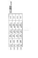
図3は、スロットの構成例を示す模式図である。スロットは、スロットヘッダ及び主信号に、誤り訂正外符号及びスタッフビットを付加し、この信号に対して誤り訂正内符号を付加した信号である。主信号には、後述するように、TLVパケット、NTPパケット、TLV NULLパケット及びスロットパディングバイトのうち、少なくともいずれかが格納される。
図4は、図1に示される伝送スロット化装置16の機能構成の例を示すブロック図である。図4に示されるスロット番号カウンタ161、設定情報受信部162、容量算出部163、伝送スロット化部164、TLVパケット受信部165、NTP(Network Time Protocol)パケット生成部166、スロットパディングバイト生成部167及びTLV NULLパケット生成部168の機能は、CPUがFPGAに所定の処理を実行させることで実現される。なお、伝送スロット化装置16は、FPGAの代わりにLSIを備えることで、図4に示される機能を実現するようにしても構わない。また、伝送スロット化装置16は、ソフトウェアにより、図4に示される機能を実現しても構わない。
スロット番号カウンタ161は、フレーム同期信号を受信すると、カウント値を1とした後、伝送クロックを用いてカウントを再開する。スロット番号カウンタ161は、図3に示されるスロット構造のデータを伝送するクロック数が経過すると、スロット番号を1増加させ、次のスロットの伝送クロック数をカウントする。これにより、フレームの開始と共にカウントが開始されることとなる。スロット番号カウンタ161は、カウント値を容量算出部163及び選択部1641へ出力する。
設定情報受信部162は、伝送主信号についてのフレーム毎の伝送モードを設定する設定情報を受信する。設定情報受信部162は、設定情報を容量算出部163及び伝送スロット化部164へ出力する。
なお、設定情報に含まれる符号化率は、例えば、図3における符号化率にて示されるように設定可能であり、符号化率の変動に応じて主信号ビット数も変動する。
また、設定情報に含まれる変調方式は、例えば、16値振幅位相変調方式(16APSK)、8相位相変調方式(8PSK)、4相位相変調方式(QPSK)及び2分のπシフト2相変調方式(π/2シフトBPSK)等である。16APSKでは、スロットの単位を5とした場合、有効スロット数が4、無効スロット数が1である。また、8PSKでは、スロットの単位を5とした場合、有効スロット数が3、無効スロット数が2である。また、QPSKでは、スロットの単位を5とした場合、有効スロット数が2、無効スロット数が3である。また、π/2シフトBPSKでは、スロットの単位を5とした場合、有効スロット数が1、無効スロット数が4である。設定情報に含まれる変調方式と符号化率との組み合わせにより、5スロット毎の主信号総ビット数が決定する。
また、設定情報に含まれる変調方式と符号化率との組み合わせは、1種類に限定されない。設定情報に含まれる変調方式と符号化率との組み合わせは、2種類以上であっても構わない。組み合わせが複数ある場合、スロットへの伝送モードの割り当ては、スロット番号1から昇順に、多値数の大きい変調方式、同じ変調方式の場合、符号化率の高いものから順に行われる。
容量算出部163は、スロット番号カウンタ161から出力されるカウント値と、設定情報受信部162から出力される設定情報とを受信する。容量算出部163は、フレーム中における最初のカウント値、すなわち、「1」を受信すると、符号化率により決定される主信号ビット数と、変調方式から決定される有効スロットと無効スロットとの割合とに基づき、フレームについての有効な主信号の容量を、フレーム主信号容量として算出する。また、容量算出部163は、スロット番号カウンタ161から出力されるカウント値を受信すると、カウント値が示す番号で表されるスロットにおける有効な主信号の容量を、スロット主信号容量として算出する。容量算出部163は、フレーム主信号容量及びスロット主信号容量を算出すると、算出したフレーム主信号容量についての情報、及び、算出したスロット主信号容量についての情報を伝送スロット化部164へ出力する。
設定情報に含まれる変調方式と符号化率との組み合わせが2種類以上ある場合、容量算出部163は、組み合わせ毎に擬似的なフレーム主信号容量を算出する。容量算出部163は、設定情報に含まれる変調方式と符号化率との組み合わせに従って割り当てられたスロット開始位置で擬似的なスロット主信号容量を用いる。
TLVパケット受信部165は、TLV多重化装置15から出力されるTLVパケットを受信する。TLVパケット受信部165は、バッファ(図示せず)を備え、受信したTLVパケットをバッファに保持する。TLVパケット受信部165は、伝送スロット化部164からの指示に応じ、保持するTLVパケットを伝送スロット化部164へ出力する。
NTPパケット生成部166は、NTP形式のIPパケットを生成する。NTPパケット生成部166は、NTP形式を含むIPパケットをTLVパケットに格納することで、NTPパケットを生成する。
なお、ARIB STD-B44 2.0版では、NTPパケットを、TLVストリームID毎に割り当てられたスロットのうち、フレーム中の最初のスロットの先頭に配置することが規定されている。NTPパケットの遅延変動を抑えるためである。なお、NTPパケットは、フレーム毎に必ずしも含める必要はない。また、同一TLVストリームID中に変調方式と符号化率との組み合わせが2種類以上ある場合、誤り耐性が最も強い組み合わせとなるスロットの最初のスロットの先頭に、NTPパケットを配置しても良い。
NTPパケット生成部166は、伝送スロット化部164から、NTPパケットを挿入するタイミングの通知を受け、そのときのNTP時刻(システム時刻)を含むNTPパケットを伝送スロット化部164へ出力する。なお、NTPパケット生成部166は、NTP時刻に対し、外部から設定されるオフセットを加算又は減算して補正してもよい。
スロットパディングバイト生成部167は、伝送スロット化部164からの指示に応じ、予め設定されるデータ列をスロットパディングバイトとして生成する。TLVパケットの先頭バイトは、図2に記載するように、「0x7f」である。スロットパディングバイト生成部167は、「0x7f」とは異なるデータ列、例えば、「0x7e」をスロットパディングバイトとして生成する。なお、スロットパディングバイトは、「0x7e」に限られず、「0x7f」以外であればよい。
また、スロットパディングバイト生成部167は、伝送主信号における最後の有効スロットの残容量が3バイトである場合のスロットパディングバイトを「0x7e」とし、残容量が2バイトである場合のスロットパディングバイトを「0x7d」とし、残容量が1バイトである場合のスロットパディングバイトを「0x7c」と、下位2ビットが残容量を表すようにしてもよい。スロットパディングバイト生成部167は、生成したスロットパディングバイトを伝送スロット化部164へ出力する。
TLV NULLパケット生成部168は、伝送スロット化部164からの指示を受信し、指示される容量のTLV NULLパケットを生成する。TLV NULLパケット生成部168は、生成したTLV NULLパケットを伝送スロット化部164へ出力する。なお、TLV NULLパケット生成部168により生成されるTLV NULLパケットは、2パケット以上であってもよい。例えば、TLV NULLパケット生成部168は、指示される容量が所定の容量、例えば1500バイトを超える場合、1500バイトを最大容量として複数のTLV NULLパケットを生成する。
伝送スロット化部164は、選択部1641、TLVバイト数抽出部1642、残量算出部1643及びスロット情報多重部1644を備える。
TLVバイト数抽出部1642は、TLVパケット受信部165から出力されるTLVパケット、又は、NTPパケット生成部166から出力されるNTPパケットを受信する。TLVバイト数抽出部1642は、受信したTLVパケット又はNTPパケットから図2に示されるデータ長を抽出し、TLVパケット又はNTPパケットに含まれるデータ容量を取得する。TLVバイト数抽出部1642は、取得したデータ容量についての情報を残量算出部1643へ出力する。
残量算出部1643は、容量算出部163から出力されるフレーム主信号容量についての情報、容量算出部163から出力されるスロット主信号容量についての情報、及び、TLVバイト数抽出部1642から出力されるデータ容量についての情報を受信する。残量算出部1643は、フレーム主信号容量からデータ容量を順次差し引くことで、フレーム残容量を算出する。残量算出部1643は、算出したフレーム残容量を選択部1641へ出力する。残量算出部1643は、フレーム主信号容量からデータ容量を順次差し引くことで、スロット残容量を算出する。残量算出部1643は、算出したスロット残容量を選択部1641へ出力する。
選択部1641は、スロット番号カウンタ161から出力されるカウント値が示す番号で表されるスロットにTLVパケット、NTPパケット又はTLV NULLパケットを格納する。
選択部1641は、スロットにTLVパケット、NTPパケット又はTLV NULLパケットを格納すると、残量算出部1643から出力されるスロット残容量から、格納したデータの容量を減算することで、現状のスロット残容量を算出する。また、選択部1641は、スロットにTLVパケット、NTPパケット又はTLV NULLパケットを格納すると、残量算出部1643から出力されるフレーム残容量から、格納したデータの容量を減算することで、現状のフレーム残容量を算出する。
選択部1641は、スロットにTLVパケット、NTPパケット又はTLV NULLパケットを格納したことで、フレームにおける最後の有効スロットのスロット残容量が4バイト未満となる場合、スロットパディングバイト生成部167へ、スロットパディングバイトの要求指示を出力する。このとき、選択部1641は、スロットパディングバイト生成部167に対し、同一のスロットパディングバイト、例えば、「0x7e」を複数バイト分要求してもよい。
また、選択部1641は、スロット残容量が3バイトである場合は「0x7e」を3バイト分要求し、スロット残容量が2バイトである場合は「0x7d」を2バイト分要求し、スロット残容量が1バイトである場合は「0x7c」を1バイト分要求してもよい。なお、選択部1641によるスロットパディングバイトの要求は、上記に限定されず、様々な態様が想定可能である。例えば、選択部1641は、スロット残容量が3バイトである場合は「0x7e」、「0x7d」及び「0x7c」を要求し、スロット残容量が2バイトである場合は「0x7d」及び「0x7c」を要求し、スロット残容量が1バイトである場合は「0x7c」を要求しても構わない。
選択部1641は、設定情報受信部162から出力される設定情報に基づき、スロット番号カウンタ161から出力されるカウント値が示す番号で表されるスロットの先頭にNTPパケットを格納する必要があるか否かを判断する。必要と判断した場合、選択部1641は、NTPパケット生成部166へNTPパケットの要求指示を出す。選択部1641は、NTPパケット生成部166から出力されるNTPパケットをスロットへ格納する。
選択部1641は、フレーム残容量及びスロット残容量に応じた容量のTLV NULLパケットを生成するようにTLV NULLパケット生成部168へ指示する。選択部1641は、TLV NULLパケット生成部168から出力されるTLV NULLパケットを受信すると、受信したTLV NULLパケットを、スロットに格納する。
選択部1641は、データを格納したスロットをスロット情報多重部1644へ出力する。
スロット情報多重部1644は、容量算出部163から出力されるフレーム主信号容量についての情報、容量算出部163から出力されるスロット主信号容量についての情報、設定情報受信部162から出力される設定情報、及び、選択部1641から出力されるスロットを受信する。スロット情報多重部1644は、受信したフレーム主信号容量、スロット主信号容量及び設定情報に基づき、受信したスロットについてのスロット情報を作成する。スロット情報は、同期信号、信号点配置情報及びTMCC情報を含む。信号点配置情報は、スロット毎に包含される最初のパケットの先頭位置、及び、スロット毎に包含される最後のパケットの末尾の位置を示す。TMCC情報は、符号化率及び変調方式を含む伝送モードについての情報、及び、TLVストリームIDについての情報等を含む。スロット情報多重部1644は、生成したスロット情報を受信したスロットに多重し、スロット情報を多重したスロットを送信処理装置17へ出力する。図5は、スロット情報多重部1644が送信処理装置17へ出力する伝送主信号のスロット構成を示す模式図である。
送信処理装置17は、例えば、CPU、CPUが処理を実行する際に用いるメモリ、及び、CPUからの制御に従って所定の処理を実行するFPGA等を備える。CPUがFPGAに所定の処理を実行させることで、送信処理装置17は、伝送主信号に対する処理を実行する。すなわち、送信処理装置17は、伝送スロット化装置16から出力される伝送主信号を受信し、受信した伝送主信号を、スロット毎に割り当てられた変調方式で変調する。送信処理装置17は、変調後の信号に対して所定の送信処理を実施し、放送波を生成する。送信処理装置17は、放送波を送信する。
なお、送信処理装置17は、FPGAの代わりにLSIを備えるようにしても構わない。また、送信処理装置17は、ソフトウェアにより所定の処理を実行するようにしても構わない。
次に以上のように構成される伝送スロット化装置16の動作を詳細に説明する。図6は、図4に示される選択部1641が受信したデータをスロットに格納する際の処理の例を示すフローチャートである。なお、図6では、フレーム中における伝送モードが1つ、すなわち、設定情報に含まれる変調方式と符号化率との組み合わせが1つである場合を例に説明する。
まず、選択部1641は、スロット番号カウンタ161からカウント値を受信する(ステップS61)。選択部1641は、受信したカウント値が1であるか否かを判断する(ステップS62)。受信したカウント値が1である場合(ステップS62のYes)、選択部1641は、新たなフレームが開始したことを認識する(ステップS63)。受信したカウント値が1でない場合(ステップS62のNo)、選択部1641は、カウント値が示す番号で表されるスロットにNTPパケットを格納するか否かを判断する(ステップS64)。
スロットにNTPパケットを格納する必要がある場合(ステップS64のYes)、選択部1641は、現スロットの先頭にNTPパケットを格納する(ステップS65)。スロットにNTPパケットを格納する必要がない場合(ステップS64のNo)、選択部1641は、現スロットが現フレームにおける最後の有効スロットであるか否かを判断する(ステップS66)。
選択部1641は、現スロットにデータを格納すると、残量算出部1643から出力されるスロット残容量から、格納したデータの容量を減算することで、現状のスロット残容量を更新する。また、選択部1641は、現スロットにデータを格納すると、残量算出部1643から出力されるフレーム残容量から、格納したデータの容量を減算することで、現状のフレーム残容量を更新する(ステップS67)。
続いて、選択部1641は、現スロットにおけるスロット残容量が0であるか否かを判断する(ステップS68)。現スロットにおけるスロット残容量が0である場合(ステップS68のYes)、選択部1641は、現フレームにおけるフレーム残容量が0であるか否かを判断する(ステップS69)。現スロットにおけるスロット残容量が0でない場合(ステップS68のNo)、選択部1641は、処理をステップS66へ移行する。
現フレームにおけるフレーム残容量が0である場合(ステップS69のYes)、選択部1641は、次フレームが開始されるまで待機する(ステップS610)。現フレームにおけるフレーム残容量が0でない場合(ステップS69のNo)、選択部1641は、処理をステップS61へ移行する。
ステップS66において、現スロットが現フレームにおける最後の有効スロットである場合(ステップS66のYes)、選択部1641は、現スロットのスロット残容量が4バイト未満であるか否かを判断する(ステップS611)。現スロットが現フレームにおける最後の有効スロットでない場合(ステップS66のNo)、選択部1641は、現スロットに格納すべきTLVパケットが存在するか否かを判断する(ステップS612)。
ステップS611において、現スロットのスロット残容量が4バイト未満である場合(ステップS611のYes)、選択部1641は、4バイト未満の領域に、スロットパディングバイト生成部167から出力されるスロットパディングバイトを格納し(ステップS613)、処理をステップS610へ移行する。
ステップS612において、現スロットに格納すべきTLVパケットが存在する場合(ステップS612のYes)、選択部1641は、現フレームにこのTLVパケットを格納できないか否か、すなわち、現スロットにTLVパケットを格納すると現フレームのフレーム残容量が0を下回るか否かを判断する(ステップS614)。現スロットに格納すべきTLVパケットが存在しない場合(ステップS612のNo)、選択部1641は、TLV NULLパケット生成部168から出力されるTLV NULLパケットを現スロットに格納し(ステップS615)、処理をステップS67へ移行する。
現スロットにTLVパケットを格納すると現フレームのフレーム残容量が0を下回る場合(ステップS614のYes)、選択部1641は、現スロットと、現フレームにおける最後の有効スロットまでを連結し、この連結スロットに、このTLVパケットではなくTLV NULLパケットを格納する(ステップS616)。現スロットにTLVパケットを格納すると現フレームのフレーム残容量が0を下回る場合(ステップS614のNo)、選択部1641は、現スロットにTLVパケットを格納すると現スロットのスロット残容量が0を下回るか否かを判断する(ステップS617)。
現スロットにTLVパケットを格納すると現スロットのスロット残容量が0を下回る場合(ステップS617のYes)、選択部1641は、TLVパケットを、現スロットに格納可能な容量の第1のTLVパケットと、その他の第2のTLVパケットとに分割する(ステップS618)。選択部1641は、分割した第1のTLVパケットを現スロットに格納し(ステップS619)、処理をステップS67へ移行する。現スロットにTLVパケットを格納すると現スロットのスロット残容量が0以上となる場合(ステップS617のNo)、選択部1641は、TLVパケットを現スロットに格納し(ステップS620)、処理をステップS67へ移行する。
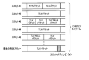
選択部1641が図6に記載する処理を実行することにより、図7に示されるようなスロット群がスロット情報多重部1644へ出力されることになる。図7によれば、最後の有効スロットの末尾にスロットパディングバイトが格納されている。
なお、図6では、フレーム中における伝送モードが1つである場合を例に説明した。しかしながら、これに限定されない。選択部1641は、フレーム中における伝送モードが2つ以上ある場合であっても同様な動作を実施することが可能である。
フレーム中における伝送モードが2つ以上ある場合、容量算出部163は、設定情報に従い、伝送モード毎に有効な主信号の容量を、フレーム主信号容量として算出する。
残量算出部1643は、伝送モード毎に算出されるフレーム主信号容量から、TLVバイト数抽出部1642から出力されるデータ容量を減算することで、伝送モード毎のフレーム残容量を算出する。
選択部1641は、設定情報に示される、スロットへの伝送モードの割り当てに従い、フレーム残容量及びスロット残容量を参照しながら、スロットにTLVパケットを格納する。
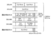
図8は、TLVストリームが1つであり、かつ、伝送モードが2つの場合のスロット構成を示す図である。図8において、スロット#1~#60に割り当てられる伝送モードの変調方式の多値数は、スロット#61~#120に割り当てられる伝送モードの変調方式の多値数よりも大きいものとする。このとき、スロット#61~#120に割り当てられる伝送モードの方が妨害に強いため、NTPパケットは、スロット#61の先頭に配置されることになる。また、図8によれば、各伝送モードにおける最後の有効スロットの末尾にスロットパディングバイトが格納されている。
図9は、TLVストリームが3つであり、かつ、伝送モードが3つの場合のスロット構成を示す図である。図9において、スロット#1~#40に割り当てられる伝送モードについてのNTPパケットはスロット#1の先頭に格納され、スロット#41~#80に割り当てられる伝送モードについてのNTPパケットはスロット#41の先頭に格納され、スロット#81~#120に割り当てられる伝送モードについてのNTPパケットはスロット#81の先頭に格納される。また、図9によれば、スロット#1~#40に割り当てられる伝送モードにおける最後の有効スロットの末尾にスロットパディングバイトが格納されている。
以上のように、第1の実施形態に係る送信システム10は、伝送スロット化装置16の容量算出部163により、フレーム主信号容量及びスロット主信号容量を算出する。残量算出部1643は、フレーム主信号容量からTLVパケットのデータ容量を減算することで、フレーム残容量を算出し、スロット主信号容量からTLVパケットのデータ容量を減算することで、スロット残容量を算出する。そして、フレーム中の最後の有効スロットにおけるスロット残容量が4バイト未満となる場合、選択部1641は、残領域にスロットパディングバイトを格納するようにしている。これにより、第1の実施形態に係る送信システム10は、フレーム中の最後の有効スロットにおけるスロット残容量が、有効スロットにTLVパケットを格納することにより4バイト未満となる場合であっても、フレーム中の最後の有効スロットの終端までデータを格納することが可能となる。
したがって、第1の実施形態係る送信システム10によれば、フレーム中の最後の有効スロットの残容量が、フレーム中の有効スロットにTLVパケットを格納することにより4バイト未満となっても放送波を正常に送信することができる。
なお、第1のフレーム中の最後の有効スロットにおいて残された3バイトの領域と、第1のフレームに続く第2のフレームの最初のスロットとを連結し、連結したスロットにTLV NULLパケットを格納する対応策も考えられる。しかしながら、NTPパケットを格納する場合、その位置が最初のスロットにおける先頭と規定されているため、この対応策では第1の実施形態に係る送信システムが達成する機能には及ばない。
また、第1の実施形態では、スロットパディングバイト生成部167は、残容量に応じた複数種類のスロットパディングバイトを生成する。そして、選択部1641は、残容量に応じたスロットパディングバイトを格納するようにしている。これにより、受信システム20が伝送主信号に含まれるスロットパディングバイトを受信した際、スロットパディングバイトが何バイト分格納されているのかを把握することが可能となる。
(受信システム)
図10は、図1に示される受信システム20の構成を示すブロック図である。図10に示される受信システム20は、受信処理装置21、伝送主信号受信装置22、TLV分離装置23、IP分離装置24、MMT分離装置25、デコーダ26及び付加情報解釈部27を具備する。
図10は、図1に示される受信システム20の構成を示すブロック図である。図10に示される受信システム20は、受信処理装置21、伝送主信号受信装置22、TLV分離装置23、IP分離装置24、MMT分離装置25、デコーダ26及び付加情報解釈部27を具備する。
受信処理装置21は、放送ネットワーク等の伝送路を介して到来する放送波を受信する。受信処理装置21は、受信した放送波に対して所定の受信処理を施すと共に、スロット毎に割り当てられた変調方式に対応する復調方式を用いた復調処理を実施することで、放送波を伝送主信号に変換する。受信処理装置21は、伝送主信号を伝送主信号受信装置22へ出力する。
図11は、図10に示される伝送主信号受信装置22の機能構成の例を示すブロック図である。図10に示されるデータ分離部221、NTP時刻再生部222、スロット情報解釈部223及びスロットパディングバイト除去部224の機能は、CPUがFPGAに所定の処理を実行させることで実現される。なお、伝送主信号受信装置22は、FPGAの代わりにLSIを備えることで、図11に示される機能を実現するようにしても構わない。また、伝送主信号受信装置22は、ソフトウェアにより、図11に示される機能を実現しても構わない。
データ分離部221は、受信処理装置21から出力される伝送主信号を受信する。データ分離部221は、受信した伝送主信号に含まれるスロットから、スロットに付加されているスロット情報を分離する。データ分離部221は、分離したスロット情報をスロット情報解釈部223へ出力する。
また、データ分離部221は、受信した伝送主信号に含まれるスロットのスロットヘッダを参照し、スロットから主信号を取り出す。データ分離部221は、主信号に含まれるNTPパケットをNTP時刻再生部222へ出力する。また、データ分離部221は、主信号に含まれるNTPパケット以外のデータを、スロットパディングバイト除去部224へ出力する。
NTP時刻再生部222は、データ分離部221から出力されるNTPパケットに基づき、NTP時刻情報を生成する。NTP時刻再生部222は、生成したNTP時刻情報と内部でカウントする時刻情報とが同期するよう内部でカウントするクロックを調整し、内部でカウントする時刻情報を後段の装置へ出力する。クロックの調整は、例えば、NTP時刻情報を受信したとき、内部でカウントする時刻情報の値と比較し、内部でカウントする時刻情報が進んでいる場合はクロックを低くし、遅れている場合はクロックを高くするようVCXO(Voltage Controlled Xtal Oscillator)の発振周波数を制御することで行う。
スロット情報解釈部223は、データ分離部221から出力されるスロット情報を受信する。スロット情報解釈部223は、受信したスロット情報から、スロット情報に含まれる信号点配置情報及びTMCC情報を解釈する。スロット情報解釈部223は、信号点配置情報及びTMCC情報をスロットパディングバイト除去部224へ出力する。
スロットパディングバイト除去部224は、スロットパディングバイトとなるデータ列、例えば、「0x7e」を予め記憶する。スロットパディングバイト除去部224は、スロット情報解釈部223から出力される信号点配置情報及びTMCC情報を受信する。スロットパディングバイト除去部224は、受信した信号点配置情報及びTMCC情報に基づき、伝送主信号の伝送モード及びフレーム中の最後の有効スロットにおける最後のパケットの末尾の位置等を把握する。スロットパディングバイト除去部224は、データ分離部221から出力されるデータを受信すると、この末尾の位置に、記憶しているデータ列が存在するか否かを判断する。受信したデータにスロットパディングバイトが存在している場合、スロットパディングバイト除去部224は、受信したデータにおける末尾の位置から最大3バイト分配置されるスロットパディングバイトを除去する。スロットパディングバイト除去部224は、スロットパディングバイトを除去した後のデータ、すなわち、TLVパケット又はTLV NULLパケットを、TLV分離装置へ出力する。
なお、スロットパディングバイト除去部224が記憶する情報は、データ列のみに限られない。例えば、スロットパディングバイト除去部224は、スロットに「0x7e」が含まれる場合は「0x7e」を含めて3バイト分が不要なデータであり、スロットに「0x7d」が含まれる場合は「0x7d」を含めて2バイト分が不要なデータであり、スロットに「0x7c」が含まれる場合は「0x7c」を含めて1バイト分が不要なデータである旨の情報を予め記憶していてもよい。このとき、スロットパディングバイト除去部224は、データ分離部221から出力されるデータに含まれるスロットパディングバイトに応じ、このデータに含まれる不要なデータを除去する。
TLV分離装置23は、伝送主信号受信装置22から出力されるTLVパケット及びTLV NULLパケットを受信する。TLV分離装置23は、受信したTLVパケットからIPパケットを取り出す。TLV分離装置23は、取り出したIPパケットをIP分離装置24へ出力する。
IP分離装置24は、TLV分離装置23から出力されるIPパケットを受信する。IP分離装置24は、受信したIPパケットからMMTPパケットを取り出す。IP分離装置24は、取り出したMMTPパケットをMMT分離装置25へ出力する。
MMT分離装置25は、IP分離装置24から出力されるMMTPパケットを受信する。MMT分離装置25は、受信したMMTPパケットから符号化信号と、付加情報とを取り出す。MMT分離装置25は、取り出した符号化信号をデコーダ26へ出力し、取り出した付加情報を付加情報解釈部27へ出力する。
デコーダ26は、MMT分離装置25から出力される符号化信号を受信し、予め設定される方式に従って復号することで、符号化信号を映像・音声信号へ変換する。デコーダ26は、映像・音声信号を後段の装置へ出力する。
付加情報解釈部27は、MMT分離装置25から出力される付加情報を受信する。付加情報解釈部27は、受信した付加情報から読み出される情報を後段の装置へ出力する。
以上のように第1の実施形態に係る受信システム20では、伝送主信号受信装置22は、スロットから主信号を取り出す。伝送主信号受信装置22は、スロットパディングバイトとなるデータ列を予め記憶する。そして、伝送主信号受信装置22は、主信号にスロットパディングバイトが含まれる場合、主信号からスロットパディングバイトを除去するようにしている。これにより、伝送主信号受信装置22は、伝送主信号を構成するスロットにスロットパディングバイトが含まれている場合であっても、伝送主信号からTLVパケットを正常に取り出すことが可能となる。
したがって、第1の実施形態に係る伝送主信号受信装置22によれば、送信システム10から送信される伝送主信号にスロットパディングバイトが含まれている場合であっても、受信システム20における放送波の正常な受信を実現することができる。
(第2の実施形態)
第1の実施形態では、伝送スロット化装置16が、伝送主信号における最後の有効スロットのスロット残容量が4バイト未満となった場合、空き領域にスロットパディングバイトを格納する場合を説明した。第2の実施形態では、伝送スロット化装置18が、伝送主信号における最後の有効スロットのスロット残容量が4バイト未満とならないように、スロットにパケットを格納する場合を説明する。
第1の実施形態では、伝送スロット化装置16が、伝送主信号における最後の有効スロットのスロット残容量が4バイト未満となった場合、空き領域にスロットパディングバイトを格納する場合を説明した。第2の実施形態では、伝送スロット化装置18が、伝送主信号における最後の有効スロットのスロット残容量が4バイト未満とならないように、スロットにパケットを格納する場合を説明する。
図12は、第2の実施形態に係る伝送スロット化装置18の機能構成の例を示すブロック図である。図12に示されるスロット番号カウンタ161、設定情報受信部162、容量算出部163、伝送スロット化部181、TLVパケット受信部165、NTPパケット生成部166及びTLV NULLパケット生成部168の機能は、CPUがFPGAに所定の処理を実行させることで実現される。なお、伝送スロット化装置18は、FPGAの代わりにLSIを備えることで、図12に示される機能を実現するようにしても構わない。また、伝送スロット化装置18は、ソフトウェアにより、図12に示される機能を実現しても構わない。
伝送スロット化部181は、選択部1811、TLVバイト数抽出部1642、残量算出部1643及びスロット情報多重部1644を備える。
選択部1811は、スロット番号カウンタ161から出力されるカウント値が示す番号で表されるスロットにTLVパケット、NTPパケット又はTLV NULLパケットを格納する。
選択部1811は、スロットにTLVパケット、NTPパケット又はTLV NULLパケットを格納すると、残量算出部1643から出力されるスロット残容量から、格納したデータの容量を減算することで、現状のスロット残容量を算出する。また、選択部1811は、スロットにTLVパケット、NTPパケット又はTLV NULLパケットを格納すると、残量算出部1643から出力されるフレーム残容量から、格納したデータの容量を減算することで、現状のフレーム残容量を算出する。
選択部1811は、設定情報受信部162から出力される設定情報に基づき、スロット番号カウンタ161から出力されるカウント値が示す番号で表されるスロットの先頭にNTPパケットを格納する必要があるか否かを判断する。必要と判断した場合、選択部1811は、NTPパケット生成部166へNTPパケットの要求指示を出す。選択部1811は、NTPパケット生成部166から出力されるNTPパケットをスロットへ格納する。
選択部1811は、フレーム残容量及びスロット残容量に応じた容量のTLV NULLパケットを生成するようにTLV NULLパケット生成部168へ指示する。選択部1811は、TLV NULLパケット生成部168から出力されるTLV NULLパケットを受信すると、受信したTLV NULLパケットを、スロットに格納する。
選択部1811は、データを格納したスロットをスロット情報多重部1644へ出力する。
次に図12に示される選択部1811が、受信したパケットをスロットに格納する際の処理を詳細に説明する。図13は、選択部1811がパケットをスロットに格納する際の処理を示すフローチャートである。なお、図13では、フレーム中における伝送モードが1つの場合を例に説明する。
まず、選択部1811は、スロット番号カウンタ161からカウント値を受信する(ステップS131)。選択部1811は、受信したカウント値が1であるか否かを判断する(ステップS132)。受信したカウント値が1である場合(ステップS132のYes)、選択部1811は、新たなフレームが開始したことを認識する(ステップS133)。受信したカウント値が1でない場合(ステップS132のNo)、選択部1811は、カウント値が示す番号で表されるスロットにNTPパケットを格納するか否かを判断する(ステップS134)。
スロットにNTPパケットを格納する必要がある場合(ステップS134のYes)、選択部1811は、現スロットの先頭にNTPパケットを格納する(ステップS135)。スロットにNTPパケットを格納する必要がない場合(ステップS134のNo)、選択部1811は、現スロットに格納すべきTLVパケットが存在するか否かを判断する(ステップS136)。
選択部1811は、現スロットにデータを格納すると、残量算出部1643から出力されるスロット残容量から、格納したデータの容量を減算することで、現状のスロット残容量を更新する。また、選択部1811は、現スロットにデータを格納すると、残量算出部1643から出力される、フレーム残容量から、格納したデータの容量を減算することで、現状のフレーム残容量を更新する(ステップS137)。
続いて、選択部1811は、現スロットにおけるスロット残容量が0であるか否かを判断する(ステップS138)。現スロットにおけるスロット残容量が0である場合(ステップS138のYes)、選択部1811は、現フレームにおけるフレーム残容量が0であるか否かを判断する(ステップS139)。現スロットにおけるスロット残容量が0でない場合(ステップS138のYes)、選択部1811は、処理をステップS136へ移行する。
現フレームにおけるフレーム残容量が0である場合(ステップS139のYes)、選択部1811は、次フレームが開始されるまで待機する(ステップS1310)。現フレームにおけるフレーム残容量が0でない場合(ステップS139のNo)、選択部1811は、処理をステップS131へ移行する。
ステップS136において、現スロットに格納すべきTLVパケットが存在する場合(ステップS136のYes)、選択部1811は、現スロットにTLVパケットを格納すると現フレームのフレーム残容量が4バイト未満となるか否かを判断する(ステップS1311)。現スロットに格納すべきTLVパケットが存在しない場合(ステップS136のNo)、選択部1811は、TLV NULLパケット生成部168から出力されるTLV NULLパケットを現スロットに格納し(ステップS1312)、処理をステップS137へ移行する。
現スロットにTLVパケットを格納すると現フレームのフレーム残容量が4バイト未満となる場合(ステップS1311のYes)、選択部1811は、現スロットと、現フレームにおける最後の有効スロットまでを連結し、この連結スロットに、TLV NULLパケットを格納する(ステップS1313)。現スロットにTLVパケットを格納すると現フレームのフレーム残容量が4バイト以上となる場合(ステップS1311のNo)、選択部1811は、現スロットにTLVパケットを格納すると現スロットのスロット残容量が0を下回るか否かを判断する(ステップS1314)。
現スロットにTLVパケットを格納すると現スロットのスロット残容量が0を下回る場合(ステップS1314のYes)、選択部1811は、TLVパケットを、現スロットに格納可能な容量の第1のTLVパケットと、その他の第2のTLVパケットとに分割する(ステップS1315)。選択部1811は、分割した第1のTLVパケットを現スロットに格納し(ステップS1316)、処理をステップS137へ移行する。現スロットにTLVパケットを格納すると現スロットのスロット残容量が0以上となる場合(ステップS1314のNo)、選択部1811は、TLVパケットを現スロットに格納し(ステップS1317)、処理をステップS137へ移行する。
なお、図13では、フレーム中における伝送モードが1つである場合を例に説明した。しかしながら、これに限定されない。選択部1811は、フレーム中における伝送モードが2つ以上ある場合であっても同様な動作を実施することが可能である。
以上のように、第2の実施形態に係る送信システム10は、伝送スロット化装置18の容量算出部163により、フレーム主信号容量及びスロット主信号容量を算出する。残量算出部1643は、フレーム主信号容量からTLVパケットのデータ容量を減算することで、フレーム残容量を算出し、スロット主信号容量からTLVパケットのデータ容量を減算することで、スロット残容量を算出する。そして、スロットにTLVパケットを格納すると現フレームのフレーム残容量が4バイト未満となる場合、選択部1811は、スロットにTLVパケットを格納せずに、スロットの終端までTLV NULLパケットを格納するようにしている。これにより、第2の実施形態に係る送信システム10は、フレーム中の最後の有効スロットの終端までTLVパケット及びTLV NULLパケットを格納することが可能となる。
したがって、第2の実施形態に係る送信システム10によれば、フレーム中の最後の有効スロットにおける残容量が4バイト未満となることを回避することが可能となる。
なお、上記第1及び第2の実施形態では、伝送スロット化装置16,18が、TLVパケットをスロットの主信号に格納する場合を例に説明した。しかしながら、TLVパケットは、データ種別を示す情報及びデータバイト数を示す情報を含む可変長パケットの例として示したものである。データ種別を示す情報及びデータバイト数を示す情報を含む可変長パケットとしては、TLVパケットの他に例えば、GSE(Generic Stream Encapsulated)パケットが挙げられる。なお、TLV多重化装置15は、可変長パケット多重化装置と記載してもよい。
また、第1及び第2の実施形態では、TLVパケットが取り得る最小バイト数は4バイトであるとし、選択部1641,1811は、最後の有効スロットの残容量が4バイト未満であるか否かに応じて処理を行うようにしている。しかしながら、選択部1641,1811が判断の基準にするバイト数は4バイト未満に限定される訳ではない。可変長パケットが取り得る最小バイト数は4バイトに限られる訳ではない。可変長パケットが取り得る最小バイト数が例えば2バイトである場合には、選択部1641,1811は、最後の有効スロットの残容量が2バイト未満であるか否かに応じて処理を行うようにしてもよい。
本発明のいくつかの実施形態を説明したが、これらの実施形態は、例として提示したものであり、発明の範囲を限定することは意図していない。これら実施形態は、その他の様々な形態で実施されることが可能であり、発明の要旨を逸脱しない範囲で、種々の省略、置き換え、変更を行うことができる。これら実施形態やその変形は、発明の範囲や要旨に含まれると同様に、特許請求の範囲に記載された発明とその均等の範囲に含まれるものである。
Claims (26)
- データの種別を示す情報と前記データのバイト数を示す情報とを含む可変長パケットを生成する可変長パケット多重化装置と、
伝送主信号を構成する複数のスロットのいずれかに前記可変長パケットを格納する伝送スロット化装置と
を具備する送信システムにおいて、
前記伝送スロット化装置は、
前記伝送主信号についての1フレーム分の設定情報を受信し、前記設定情報に基づいて1フレームの前記伝送主信号に含めることが可能なデータ容量を算出する容量算出部と、
前記可変長パケットのバイト数を抽出する抽出部と、
前記容量算出部が算出する前記データ容量と前記抽出部が抽出する前記バイト数とに基づき、前記伝送主信号の残容量を算出する残容量算出部と、
前記可変長パケットをスロットのいずれかに格納した前記伝送主信号の残容量が、可変長パケットが取り得る最小バイト数未満である場合、前記スロット中の残された領域に予め設定されるデータ列を格納し、前記データ列を格納したスロットを出力する選択部と、
前記選択部が出力するスロットにスロット情報を多重するスロット情報多重部と
を有する送信システム。 - 前記可変長パケットはTLV(Type Length Value)パケットである請求項1記載の送信システム。
- 前記選択部は、前記可変長パケットをスロットのいずれかに格納した前記伝送主信号の残容量が4バイト未満である場合、前記スロット中の残された領域に前記データ列を格納し、前記データ列を格納したスロットを出力する請求項2記載の送信システム。
- 前記設定情報に変調率と変調方式との組み合わせが複数設定され、
前記容量算出部は、前記組み合わせ毎に前記データ容量を算出し、
前記残容量算出部は、前記組み合わせ毎に前記残容量を算出し、
前記選択部は、前記組み合わせ毎に算出される残容量が前記最小バイト数未満であるか否かを判断し、残容量が前記最小バイト数未満である場合、スロット中の残された領域に前記データ列を格納する請求項1乃至3のいずれかに記載の送信システム。 - 前記データ列は、前記最小バイト数未満の各残容量に対応して予め設定され、
前記選択部は、前記各残容量に応じたデータ列を前記スロット中の残された領域に格納する請求項1乃至4のいずれかに記載の送信システム。 - 前記選択部は、1フレームの前記伝送主信号を構成する最初のスロットの先頭にNTPパケットを格納する請求項1乃至5のいずれかに記載の送信システム。
- データの種別を示す情報と前記データのバイト数を示す情報とを含む可変長パケットを生成する可変長パケット多重化装置と、
伝送主信号を構成する複数のスロットのいずれかに前記可変長パケットを格納する伝送スロット化装置と
を具備する送信システムにおいて、
前記伝送スロット化装置は、
前記伝送主信号についての1フレーム分の設定情報を受信し、前記設定情報に基づいて1フレームの前記伝送主信号に含めることが可能なデータ容量を算出する容量算出部と、
前記可変長パケットのバイト数を抽出する抽出部と、
前記容量算出部が算出する前記データ容量と前記抽出部が抽出する前記バイト数とに基づき、前記伝送主信号の残容量を算出する残容量算出部と、
前記可変長パケットをスロットのいずれかに格納すると、前記伝送主信号の残容量が、可変長パケットが取り得る最小バイト数未満となる場合、前記可変長パケットに代えてヌルパケットを前記スロットの終端まで格納し、前記ヌルパケットを格納したスロットを出力する選択部と、
前記選択部が出力するスロットにスロット情報を多重するスロット情報多重部と
を有する送信システム。 - 前記可変長パケットはTLV(Type Length Value)パケットである請求項7記載の送信システム。
- 前記選択部は、前記可変長パケットをスロットのいずれかに格納すると、前記伝送主信号の残容量が4バイト未満となる場合、前記可変長パケットに代えてヌルパケットを前記スロットの終端まで格納し、前記ヌルパケットを格納したスロットを出力する請求項8記載の送信システム。
- 前記設定情報に変調率と変調方式との組み合わせが複数設定され、
前記容量算出部は、前記組み合わせ毎に前記データ容量を算出し、
前記残容量算出部は、前記組み合わせ毎に前記残容量を算出し、
前記選択部は、前記可変長パケットを前記スロットのいずれかに格納すると、前記組み合わせ毎に算出される残容量が前記可変長パケットの最小バイト数未満となるか否かを判断し、残容量が前記可変長パケットの最小バイト数未満となる場合、前記可変長パケットに代えてヌルパケットを前記スロットの終端まで格納する請求項7乃至9のいずれかに記載の送信システム。 - 前記選択部は、1フレームの前記伝送主信号を構成する最初のスロットの先頭にNTPパケットを格納する請求項7乃至10のいずれかに記載の送信システム。
- 複数のスロットにより構成される伝送主信号についての1フレーム分の設定情報を受信し、前記設定情報に基づいて1フレームの前記伝送主信号に含めることが可能なデータ容量を算出する容量算出部と、
データの種別を示す情報と前記データのバイト数を示す情報とを含む可変長パケットのバイト数を抽出する抽出部と、
前記容量算出部が算出する前記データ容量と前記抽出部が抽出する前記バイト数とに基づき、前記伝送主信号の残容量を算出する残容量算出部と、
前記可変長パケットをスロットのいずれかに格納した前記伝送主信号の残容量が、可変長パケットが取り得る最小バイト数未満である場合、前記スロット中の残された領域に予め設定されるデータ列を格納し、前記データ列を格納したスロットを出力する選択部と、
前記選択部が出力するスロットにスロット情報を多重するスロット情報多重部と
を具備する伝送スロット化装置。 - 前記可変長パケットはTLV(Type Length Value)パケットである請求項12記載の伝送スロット化装置。
- 前記選択部は、前記可変長パケットをスロットのいずれかに格納した前記伝送主信号の残容量が4バイト未満である場合、前記スロット中の残された領域に前記データ列を格納し、前記データ列を格納したスロットを出力する請求項13記載の伝送スロット化装置。
- 前記設定情報に変調率と変調方式との組み合わせが複数設定され、
前記容量算出部は、前記組み合わせ毎に前記データ容量を算出し、
前記残容量算出部は、前記組み合わせ毎に前記残容量を算出し、
前記選択部は、前記組み合わせ毎に算出される残容量が前記最小バイト数未満であるか否かを判断し、残容量が前記最小バイト数未満である場合、スロット中の残された領域に前記データ列を格納する請求項12乃至14のいずれかに記載の伝送スロット化装置。 - 前記データ列は、前記最小バイト数未満の各残容量に対応して予め設定され、
前記選択部は、前記各残容量に応じたデータ列を前記スロット中の残された領域に格納する請求項12乃至15のいずれかに記載の伝送スロット化装置。 - 前記選択部は、1フレームの前記伝送主信号を構成する最初のスロットの先頭にNTPパケットを格納する請求項12乃至16のいずれかに記載の伝送スロット化装置。
- 複数のスロットにより構成される伝送主信号についての1フレーム分の設定情報を受信し、前記設定情報に基づいて1フレームの前記伝送主信号に含めることが可能なデータ容量を算出する容量算出部と、
データの種別を示す情報と前記データのバイト数を示す情報とを含む可変長パケットのバイト数を抽出する抽出部と、
前記容量算出部が算出する前記データ容量と前記抽出部が抽出する前記バイト数とに基づき、前記伝送主信号の残容量を算出する残容量算出部と、
前記可変長パケットをスロットのいずれかに格納すると、前記伝送主信号の残容量が、可変長パケットが取り得る最小バイト数未満となる場合、前記可変長パケットに代えてヌルパケットを前記スロットの終端まで格納し、前記ヌルパケットを格納したスロットを出力する選択部と、
前記選択部が出力するスロットにスロット情報を多重するスロット情報多重部と
を具備する伝送スロット化装置。 - 前記可変長パケットはTLV(Type Length Value)パケットである請求項18記載の伝送スロット化装置。
- 前記選択部は、前記可変長パケットをスロットのいずれかに格納すると、前記伝送主信号の残容量が4バイト未満となる場合、前記可変長パケットに代えてヌルパケットを前記スロットの終端まで格納し、前記ヌルパケットを格納したスロットを出力する請求項19記載の伝送スロット化装置。
- 前記設定情報に変調率と変調方式との組み合わせが複数設定され、
前記容量算出部は、前記組み合わせ毎に前記データ容量を算出し、
前記残容量算出部は、前記組み合わせ毎に前記残容量を算出し、
前記選択部は、前記可変長パケットを前記スロットのいずれかに格納すると、前記組み合わせ毎に算出される残容量が前記可変長パケットの最小バイト数未満となるか否かを判断し、残容量が前記可変長パケットの最小バイト数未満となる場合、前記可変長パケットに代えてヌルパケットを前記スロットの終端まで格納する請求項18乃至20のいずれかに記載の伝送スロット化装置。 - 前記選択部は、1フレームの前記伝送主信号を構成する最初のスロットの先頭にNTPパケットを格納する請求項18乃至21のいずれかに記載の伝送スロット化装置。
- 構成する複数のスロットのうち、1フレームにおける最後の有効スロットの末尾に予め設定されるデータバイト数のデータ列が格納される伝送主信号を受信し、前記受信した伝送主信号のスロットから、前記スロットに関する情報を含むスロット情報と、前記スロットに含まれる主信号を取り出すデータ分離部と、
前記スロット情報を解釈し、前記スロットに関する情報を取得するスロット情報解釈部と、
前記スロット情報解釈部が取得した情報に基づき、前記主信号に前記データ列が存在しているか否かを判断し、前記主信号に前記データ列が存在している場合、前記データ列を除去する除去部と
を具備する受信装置。 - 前記データ列は、データの種別を示す情報と前記データのバイト数を示す情報とを含む可変長パケットが取り得る最小バイト数未満の各容量に対応して予め設定され、
前記除去部は、存在する前記データ列に応じて除去する容量を認識する請求項23記載の受信装置。 - 複数のスロットにより構成される伝送主信号についての1フレーム分の設定情報に基づいて1フレームの前記伝送主信号に含めることが可能なデータ容量を算出し、
データの種別を示す情報と前記データのバイト数を示す情報とを含む可変長パケットのバイト数を抽出し、
前記データ容量と前記バイト数とに基づき、前記伝送主信号の残容量を算出し、
前記可変長パケットをスロットのいずれかに格納し、
前記可変長パケットを前記スロットのいずれかに格納した前記伝送主信号の残容量が、可変長パケットが取り得る最小バイト数未満である場合、前記スロット中の残された領域に予め設定されるデータ列を格納し、
前記データ列を格納したスロットにスロット情報を多重する伝送スロット作成方法。 - 複数のスロットにより構成される伝送主信号についての1フレーム分の設定情報に基づいて1フレームの前記伝送主信号に含めることが可能なデータ容量を算出し、
データの種別を示す情報と前記データのバイト数を示す情報とを含む可変長パケットのバイト数を抽出し、
前記データ容量と前記バイト数とに基づき、前記伝送主信号の残容量を算出し、
前記可変長パケットをスロットのいずれかに格納し、
前記可変長パケットを前記スロットのいずれかに格納すると、前記伝送主信号の残容量が、可変長パケットが取り得る最小バイト数未満となる場合、前記可変長パケットに代えてヌルパケットを前記スロットの終端まで格納し、
前記ヌルパケットを格納したスロットにスロット情報を多重する伝送スロット作成方法。
Priority Applications (3)
| Application Number | Priority Date | Filing Date | Title |
|---|---|---|---|
| CN201580077850.4A CN107408996B (zh) | 2015-03-17 | 2015-12-21 | 发送系统、传输时隙化装置、接收装置以及传输时隙制作方法 |
| US15/706,068 US10574436B2 (en) | 2015-03-17 | 2017-09-15 | Transmitting system, transmission slotting apparatus, receiving apparatus, and transmission slot generating method |
| US16/735,169 US10911213B2 (en) | 2015-03-17 | 2020-01-06 | Transmitting system, transmission slotting apparatus, receiving apparatus, and transmission slot generating method |
Applications Claiming Priority (2)
| Application Number | Priority Date | Filing Date | Title |
|---|---|---|---|
| JP2015053838A JP6290127B2 (ja) | 2015-03-17 | 2015-03-17 | 送信システム、伝送スロット化装置、受信装置及び伝送スロット作成方法 |
| JP2015-053838 | 2015-03-17 |
Related Child Applications (1)
| Application Number | Title | Priority Date | Filing Date |
|---|---|---|---|
| US15/706,068 Continuation US10574436B2 (en) | 2015-03-17 | 2017-09-15 | Transmitting system, transmission slotting apparatus, receiving apparatus, and transmission slot generating method |
Publications (1)
| Publication Number | Publication Date |
|---|---|
| WO2016147516A1 true WO2016147516A1 (ja) | 2016-09-22 |
Family
ID=56919911
Family Applications (1)
| Application Number | Title | Priority Date | Filing Date |
|---|---|---|---|
| PCT/JP2015/085702 Ceased WO2016147516A1 (ja) | 2015-03-17 | 2015-12-21 | 送信システム、伝送スロット化装置、受信装置及び伝送スロット作成方法 |
Country Status (4)
| Country | Link |
|---|---|
| US (2) | US10574436B2 (ja) |
| JP (1) | JP6290127B2 (ja) |
| CN (1) | CN107408996B (ja) |
| WO (1) | WO2016147516A1 (ja) |
Cited By (1)
| Publication number | Priority date | Publication date | Assignee | Title |
|---|---|---|---|---|
| JP2020025337A (ja) * | 2015-03-11 | 2020-02-13 | 日本放送協会 | 送信装置、プログラム、及び集積回路 |
Families Citing this family (12)
| Publication number | Priority date | Publication date | Assignee | Title |
|---|---|---|---|---|
| JP6290852B2 (ja) * | 2015-12-24 | 2018-03-07 | 日本電気株式会社 | 信号構成装置、信号構成システム、信号構成方法、および信号構成用プログラム |
| JP6290851B2 (ja) * | 2015-12-24 | 2018-03-07 | 日本電気株式会社 | 信号構成装置、信号構成システム、信号構成方法、および信号構成用プログラム |
| JP7089857B2 (ja) * | 2016-10-31 | 2022-06-23 | 日本放送協会 | 再多重化装置、送信装置、受信装置、チップ、及びプログラム |
| JP7069542B2 (ja) | 2016-12-16 | 2022-05-18 | ソニーグループ株式会社 | 送信装置、及び、送信方法 |
| KR20230019987A (ko) * | 2016-12-16 | 2023-02-09 | 소니그룹주식회사 | 송신 장치, 송신 방법, 수신 장치, 및 수신 방법 |
| JP7074426B2 (ja) | 2017-02-22 | 2022-05-24 | 日本電気株式会社 | 同期処理装置、信号処理システム、同期処理方法、および同期処理用プログラム |
| JP7164347B2 (ja) * | 2017-07-27 | 2022-11-01 | 日本放送協会 | 送信装置及び受信装置 |
| US11172268B2 (en) | 2017-07-31 | 2021-11-09 | Samsung Electronics Co., Ltd. | Method and apparatus for providing broadcast service |
| JP6744262B2 (ja) * | 2017-08-22 | 2020-08-19 | 株式会社東芝 | 電子装置及び方法 |
| US11477518B2 (en) * | 2018-01-18 | 2022-10-18 | Sony Semiconductor Solutions Corporation | Signal processing device and signal processing method |
| JP2021158394A (ja) * | 2018-06-27 | 2021-10-07 | ソニーセミコンダクタソリューションズ株式会社 | 受信装置、及び受信方法 |
| CN116055511A (zh) * | 2023-01-31 | 2023-05-02 | 苏州浪潮智能科技有限公司 | 基于rdma的分布式流计算节点数据同步方法及系统 |
Citations (4)
| Publication number | Priority date | Publication date | Assignee | Title |
|---|---|---|---|---|
| JPH10262015A (ja) * | 1996-05-08 | 1998-09-29 | Matsushita Electric Ind Co Ltd | 多重伝送方法およびシステム並びにそこで用いる音声ジッタ吸収方法 |
| JP2009049987A (ja) * | 2007-07-26 | 2009-03-05 | Nippon Hoso Kyokai <Nhk> | パケット送信装置 |
| JP2009130678A (ja) * | 2007-11-26 | 2009-06-11 | Nippon Hoso Kyokai <Nhk> | パケット多重化装置及びパケット多重化プログラム |
| WO2010106796A1 (ja) * | 2009-03-18 | 2010-09-23 | パナソニック株式会社 | コンテンツ送信装置及びコンテンツ送受信システム |
Family Cites Families (8)
| Publication number | Priority date | Publication date | Assignee | Title |
|---|---|---|---|---|
| SG71709A1 (en) | 1996-05-08 | 2000-04-18 | Matsushita Electric Industrial Co Ltd | Multiplex transmission method and system and audio jitter absorbing method used therein |
| US7397400B2 (en) * | 2005-12-02 | 2008-07-08 | Viasat, Inc. | Variable length data encapsulation and encoding |
| JP5049151B2 (ja) | 2008-01-31 | 2012-10-17 | 日本放送協会 | 受信装置及び伝送システム |
| US20090282291A1 (en) * | 2008-05-08 | 2009-11-12 | Nortel Networks Limited | Internal maintenance association end point (mep) for sharing state information |
| US8179813B2 (en) * | 2008-12-18 | 2012-05-15 | Qualcomm Incorporated | Methods and systems for ranging using ranging loading factor |
| JP5400575B2 (ja) | 2009-11-11 | 2014-01-29 | 日本放送協会 | 可変長パケットの送信装置、受信装置及びプログラム |
| JP6692057B2 (ja) * | 2014-12-10 | 2020-05-13 | パナソニックIpマネジメント株式会社 | 送信方法、受信方法、送信装置及び受信装置 |
| JP6489581B2 (ja) | 2015-03-11 | 2019-03-27 | 日本放送協会 | 送信装置、プログラム、及び集積回路 |
-
2015
- 2015-03-17 JP JP2015053838A patent/JP6290127B2/ja active Active
- 2015-12-21 CN CN201580077850.4A patent/CN107408996B/zh not_active Expired - Fee Related
- 2015-12-21 WO PCT/JP2015/085702 patent/WO2016147516A1/ja not_active Ceased
-
2017
- 2017-09-15 US US15/706,068 patent/US10574436B2/en active Active
-
2020
- 2020-01-06 US US16/735,169 patent/US10911213B2/en active Active
Patent Citations (4)
| Publication number | Priority date | Publication date | Assignee | Title |
|---|---|---|---|---|
| JPH10262015A (ja) * | 1996-05-08 | 1998-09-29 | Matsushita Electric Ind Co Ltd | 多重伝送方法およびシステム並びにそこで用いる音声ジッタ吸収方法 |
| JP2009049987A (ja) * | 2007-07-26 | 2009-03-05 | Nippon Hoso Kyokai <Nhk> | パケット送信装置 |
| JP2009130678A (ja) * | 2007-11-26 | 2009-06-11 | Nippon Hoso Kyokai <Nhk> | パケット多重化装置及びパケット多重化プログラム |
| WO2010106796A1 (ja) * | 2009-03-18 | 2010-09-23 | パナソニック株式会社 | コンテンツ送信装置及びコンテンツ送受信システム |
Cited By (1)
| Publication number | Priority date | Publication date | Assignee | Title |
|---|---|---|---|---|
| JP2020025337A (ja) * | 2015-03-11 | 2020-02-13 | 日本放送協会 | 送信装置、プログラム、及び集積回路 |
Also Published As
| Publication number | Publication date |
|---|---|
| US20200145184A1 (en) | 2020-05-07 |
| JP6290127B2 (ja) | 2018-03-07 |
| US10574436B2 (en) | 2020-02-25 |
| CN107408996B (zh) | 2019-06-28 |
| CN107408996A (zh) | 2017-11-28 |
| US20180006747A1 (en) | 2018-01-04 |
| JP2016174299A (ja) | 2016-09-29 |
| US10911213B2 (en) | 2021-02-02 |
Similar Documents
| Publication | Publication Date | Title |
|---|---|---|
| JP6290127B2 (ja) | 送信システム、伝送スロット化装置、受信装置及び伝送スロット作成方法 | |
| CN103733631B (zh) | 媒体内容收发方法和使用该方法的收发设备 | |
| RU2677572C2 (ru) | Устройство и способ передачи потока передачи и устройство обработки | |
| JP6302274B2 (ja) | 送信装置及び受信装置 | |
| JP6823277B2 (ja) | インタフェース方法 | |
| JP6368451B2 (ja) | 送信装置及び受信装置 | |
| JP2013175949A (ja) | 送信装置及び受信装置 | |
| US20190281335A1 (en) | Transmission device, transmission method, reception device, and reception method | |
| JP6575514B2 (ja) | 送信装置、送信方法、受信装置および受信方法 | |
| JP6517905B2 (ja) | 送信システム、伝送スロット化装置、及び伝送スロット作成方法 | |
| CN107852522A (zh) | 接收设备和数据处理方法 | |
| JP6333969B2 (ja) | 放送送受信装置および放送送受信方法 | |
| JP6976284B2 (ja) | 送信システム、伝送スロット化装置、及び伝送スロット作成方法 | |
| JP4192766B2 (ja) | 受信装置および方法、記録媒体、並びにプログラム | |
| JP7188510B2 (ja) | 送信方法および受信装置 | |
| JP6848797B2 (ja) | 放送再送信装置、放送受信装置、放送再送信方法、放送受信方法、放送再送信プログラムおよび放送受信プログラム | |
| JP2015159469A (ja) | 多重化装置、送信装置、送信システム、多重化方法、送信方法 | |
| JP6763440B2 (ja) | 受信装置、および通信システム | |
| JP2011239059A (ja) | デジタルデータ送信装置、受信装置、送信方法、受信方法及びプログラム | |
| KR20060064282A (ko) | Pcr 및 데이터 레이트의 보정 장치 및 보정 방법 | |
| KR20160096300A (ko) | 위성 방송 시스템을 위한 망 동기화 장치 및 방법 |
Legal Events
| Date | Code | Title | Description |
|---|---|---|---|
| 121 | Ep: the epo has been informed by wipo that ep was designated in this application |
Ref document number: 15885608 Country of ref document: EP Kind code of ref document: A1 |
|
| NENP | Non-entry into the national phase |
Ref country code: DE |
|
| 122 | Ep: pct application non-entry in european phase |
Ref document number: 15885608 Country of ref document: EP Kind code of ref document: A1 |