WO2016147362A1 - テープフィーダ - Google Patents
テープフィーダ Download PDFInfo
- Publication number
- WO2016147362A1 WO2016147362A1 PCT/JP2015/058137 JP2015058137W WO2016147362A1 WO 2016147362 A1 WO2016147362 A1 WO 2016147362A1 JP 2015058137 W JP2015058137 W JP 2015058137W WO 2016147362 A1 WO2016147362 A1 WO 2016147362A1
- Authority
- WO
- WIPO (PCT)
- Prior art keywords
- tape
- supplier
- holder
- feeder
- component
- Prior art date
- Legal status (The legal status is an assumption and is not a legal conclusion. Google has not performed a legal analysis and makes no representation as to the accuracy of the status listed.)
- Ceased
Links
Images


Classifications
-
- H—ELECTRICITY
- H05—ELECTRIC TECHNIQUES NOT OTHERWISE PROVIDED FOR
- H05K—PRINTED CIRCUITS; CASINGS OR CONSTRUCTIONAL DETAILS OF ELECTRIC APPARATUS; MANUFACTURE OF ASSEMBLAGES OF ELECTRICAL COMPONENTS
- H05K13/00—Apparatus or processes specially adapted for manufacturing or adjusting assemblages of electric components
- H05K13/02—Feeding of components
Definitions
- the present invention relates to a tape feeder configured to detachably attach a tape supplier that supplies a component supply tape in which a large number of components are arranged at a predetermined pitch to a component suction position in a slot of the feeder body.
- Patent Document 1 Japanese Patent Laid-Open No. 2013-98382
- a plurality of tape suppliers are individually detachably attached to a plurality of slots provided in the feeder body. Is configured to do.
- a tape holder portion that supports a component supply tape to be supplied to the component suction position and a plate retainer plate made of a leaf spring that suppresses the lifting of the component supply tape on the tape holder portion are provided at the front end portion of the tape supplier. It has a provided configuration.
- the tape feeder of the above-mentioned patent document 1 is designed to increase the number of tape suppliers that can be inserted into the feeder body by reducing the width of the tape supplier to the same dimension as the width of the component supply tape. . For this reason, the tape holder part and the tape pressing plate on the front end side of the tape supplier are also reduced in size and thickness, and the mechanical strength is weakened and it is easily deformed.
- a supplier insertion guide plate that covers the top side of the tape supplier inserted into the slot from above is attached, but between the supplier insertion guide plate and the slot, the tip of the tape supplier Since it is necessary to provide a clearance (gap) for inserting the side part, the tip side part of the tape supplier is lifted by the clearance, or the cover tape (top).
- the tape pressing plate for pressing the component supply tape may be deformed so as to be lifted by a tensile force when peeling the tape (also called a tape).
- a tensile force when peeling the tape also called a tape
- the problem to be solved by the present invention is to provide a tape feeder that can stabilize the component suction operation by stabilizing the height position of the component supply tape component at the component suction position on the tip side of the tape supplier. That is.
- the present invention is a tape configured to detachably mount a tape supplier for supplying a component supply tape, in which a large number of components are arranged at a predetermined pitch, to a component suction position in a slot of the feeder body.
- a supplier insertion guide member that covers the tip side portion of the tape supplier attached to the slot from above is provided, and the supplier insertion guide member is set to the tape supplier.
- a component suction opening for sucking a component in a component supply tape at the component suction position is formed, and the tape supplier includes a tape holder portion that supports the component supply tape supplied to the component suction position, Tape holding plate for holding the component supply tape from rising up on the tape holder, and the tape And a rising piece that rises upward from the side edge of the end plate or the side edge of the tape holder, and the rising piece of the tape supplier mounted in the slot is abutted against the supplier insertion guide member.
- a holder pressing portion that comes into contact is provided, and the rising piece is in contact with the holder pressing portion when the tape supplier is mounted, and is configured to press the lifting of the tape pressing plate and the tip side portion of the tape holder portion. It is characterized by being.
- the tape pressing plate is formed of an elastic plate such as a leaf spring
- the rising piece is on one side edge of the tape pressing plate
- the portion that contacts the holder pressing portion is on the inside.
- the upper surface of the component supply tape is formed between the tape pressing plate and the supplier insertion guide member by forming the bent cross section in a substantially inverted L shape and the rising piece abuts the holder pressing portion when the tape supplier is mounted. It is preferable that the cover tape peeled off is pulled in the direction opposite to the feeding direction of the component supply tape to secure a gap for recovery.
- the tape pressing plate is formed of an elastic plate such as a leaf spring
- the component supply tape is used by using the elastic deformation of the tape pressing plate. It becomes easy to insert between the holding plate and the component supply tape can be easily set.
- a rising piece having a substantially inverted L-shaped cross section is formed on one side edge of the tape pressing plate, the tape pressing plate can be prevented from rising more reliably, and the tape pressing plate and the supplier insertion guide member can be prevented from rising. In the meantime, a gap for collecting the cover tape peeled off from the upper surface of the component supply tape can be ensured.
- it may be configured to include a height position adjusting means for adjusting the height position of the holder pressing portion.
- a height position adjusting means for adjusting the height position of the holder pressing portion.
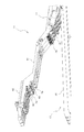
- FIG. 1 is a perspective view showing an entire feeder body according to an embodiment of the present invention with a tape supplier removed.
- FIG. 2 is a perspective view showing the structure of the rear side of the feeder body with the tape supplier removed.
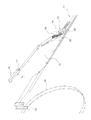
- FIG. 3 is a perspective view showing the tape supplier.
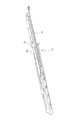
- FIG. 4 is a perspective view showing a front end portion of a tape supplier in which no component supply tape is set.
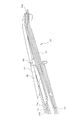
- FIG. 5 is a perspective view showing a front end portion of a tape supplier on which a component supply tape is set.
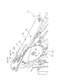
- FIG. 6 is a perspective view of the front end portion of the tape feeder as viewed obliquely from above.
- FIG. 1 is a perspective view showing an entire feeder body according to an embodiment of the present invention with a tape supplier removed.
- FIG. 2 is a perspective view showing the structure of the rear side of the feeder body with the tape supplier removed.
- FIG. 3 is a perspective view showing the tape supplier.
- FIG. 4 is a perspective view showing a front end portion of a tape supplier
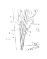
- FIG. 7 is a perspective view showing the rising piece of the tape pressing plate of the tape supplier mounted on the feeder main body, the holder pressing portion on the supplier insertion guide member side, and its peripheral portion.
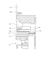
- FIG. 8 is a cross-sectional view showing the rising piece of the tape pressing plate of the tape supplier mounted on the feeder body, the holder pressing portion on the supplier insertion guide member side, and its peripheral portion.
- FIG. 9 is a perspective view showing a feeder mounting table of the component mounting machine.
- the tape feeder 11 has a lateral width of the feeder main body 13 of a conventional general tape feeder (a tape feeder capable of setting only one component supply tape) so that a plurality of component supply tapes can be set in the horizontal width direction. It is formed approximately several times the width. In this embodiment, by reducing the interval between adjacent component supply tapes, the lateral width of the feeder main body 13 is, for example, approximately four times that of a conventional general tape feeder (approximately M times, where M is an integer). , Six (N, where N is an integer greater than M) component supply tapes 19 (see FIG. 5) can be set side by side in the width direction.
- a conventional general tape feeder a tape feeder capable of setting only one component supply tape
- the component supply tape 19 is obtained by storing components in component storage recesses formed in a line at a predetermined pitch on the carrier tape 19a and attaching a cover tape 20 to the upper surface of the carrier tape 19a.
- Sprocket holes 19b are formed in a row at a predetermined pitch along the side edge (see FIG. 5).
- a reel holder 17 that houses a tape reel 16 (see FIG. 3) around which a component supply tape 19 is wound is provided at a lower portion on the rear side (removal direction side) of the feeder body 13. .
- the reel holder 17 is formed so as to store a plurality of tape reels 16 arranged in two rows in the front and rear, and is stored so that each tape reel 16 can be rotated in the reel holder 17 as the component supply tape 19 is pulled out. .
- the component supply tape 19 drawn from each tape reel 16 is guided to a component suction position by a tape supplier 21 (see FIGS. 3 to 5).
- the width of each tape supplier 21 is formed to be slightly larger than the width of the component supply tape 19 so that only one component supply tape 19 is set in each tape supplier 21.
- the feeder body 13 is provided with a plurality of slots 18 for mounting a plurality of tape suppliers 21, and each of the slots 18 is configured to be detachably mounted with one tape supplier 21.
- a reel hooking portion 22 for holding the tape reel 16 on the tape supplier 21 removed from the feeder main body 13 is provided at the rear end portion of each tape supplier 21.
- the tape reel 16 can be hooked and held.
- the tape supplier 21 is provided with a cover tape peeling device 23 that peels off the cover tape that covers the upper surface of the component supply tape 19, and a cover tape collection case 24 that collects the cover tape peeled off from the component supply tape 19.
- the cover tape peeling device 23 includes a peeling roller 25, a tension roller 26, and a pair of cover tape feed gears 28 and 29. The cover tape peeled off by the peeling roller 25 is passed over the tension roller 26 and covered with the cover tape. It is sandwiched between the feed gears 28 and 29 and fed into the cover tape collecting case 24.
- the drive source of the cover tape feed gears 28 and 29 is provided on the feeder main body 13 side.
- one cover tape feed gear 28 is connected to the drive gear 34 (on the feeder main body 13 side).
- the cover tape feed gears 28 and 29 are rotationally driven by meshing with each other (see FIG. 2).
- the feeder body 13 is provided with a drive device 31 (see FIG. 2) for driving the drive gear 34.
- the drive device 31 and the drive gear 34 are respectively provided in the same number as the number of tape suppliers 21 that can be mounted on the feeder main body 13, and the feed amount (peeling amount) of the cover tape is controlled independently for each tape supplier 21. It can be done.
- the same number of sprocket drive units 43 (see FIG. 6) as the number of component supply tapes 19 that can be set on the feeder main body 13 are arranged side by side in the width direction on the front end side of the feeder main body 13.
- the sprocket 44 is rotationally driven to pitch-feed the component supply tape 19.
- a connector 67 for connecting a signal line and a power line of the feeder main body 13 to a connector 68 (see FIG. 9) of a feeder set base 66 of the component mounting machine and two positioning pins are provided on the front end surface of the feeder main body 13.
- 69 and 70 are provided, and the two positioning pins 69 and 70 are inserted into the positioning holes 71 and 72 (see FIG. 9) of the feeder set base 66 of the component mounting machine, so that the feeder main body 13 is placed on the feeder set base 66.
- the attachment position is positioned, and the connector 67 of the feeder body 13 is inserted and connected to the connector 68 of the feeder set base 66.
- a guide groove 74 having a reverse T-shaped cross section for supporting the tape feeder 11 in a vertical position is provided on the upper surface of the feeder set base 66, and a guide rail having a reverse T-shaped cross section provided on the lower surface side of the feeder body 13. (Not shown) is inserted into the guide groove 74 from the front side, whereby the tape feeder 11 is supported in a vertically placed state on the feeder set base 66 and a clamp member (not shown) provided on the feeder main body 13. ) Fits into the clamp groove 79 of the feeder set base 66 and presses the feeder main body 13 forward (to the connector 68 side of the feeder set base 66) to clamp the feeder main body 13 on the feeder set base 66. Positioned in the front-rear direction and detachably attached.
- an arm-like holding member 41 that holds the upper side of the cover tape collecting case 24 of the tape supplier 21 mounted in the slot 18 is provided on the upper side of the feeder body 13.
- An operation panel 42 for operating the tape feeder 11 is provided on the rear end side (operator side) of the upper surface of the member 41.
- the operation panel 42 is provided with operation keys for inputting various operation signals such as a tape supplier attachment work start signal for each tape supplier 21 attached to the feeder main body 13.
- a handle portion 76 that is gripped by an operator when the tape supplier 21 is attached to or detached from the feeder main body 13 is provided at the rear upper end of the cover tape collecting case 24 of the tape supplier 21, and the handle portion 76 is pushed in.
- Positioning pins 77 serving as positioning means for positioning the tape supplier 21 with respect to the holding member 41 are provided at the end on the direction side.
- a positioning hole 78 (see FIG. 2) that is a positioning means for positioning the tape supplier 21 is formed in the lower step portion of the operation panel 42 of the holding member 41 of the feeder body 13, and the tape supplier 21. Is inserted into the feeder main body 13, the positioning pin 77 of the handle 76 is inserted into the positioning hole 78 on the lower side of the operation panel 42, so that the tape supplier 21 attached to the feeder main body 13 can operate the operation panel 42 of the holding member 41. Is positioned accurately with respect to the lower surface of the plate.
- the tape supplier 21 can be attached to the slot 18 of the feeder body 13 with the tape feeder 11 set on the feeder set base 66 of the component mounting machine.
- a plate-like supplier insertion guide member 45 is attached to the upper surface of the front end portion of the feeder body 13 so as to cover the front end portion of the tape supplier 21 mounted in the slot 18 from above.
- the guide member 45 is formed with a component suction opening 46 for sucking a component in the component supply tape 19 set in the tape supplier 21 at a component suction position.
- the component suction opening 46 of the supplier insertion guide member 45 also serves to position the component supply tape 19 in the width direction by fitting and holding both ends of the component supply tape 19 in the vicinity of the component suction position. .
- a tape-shaped tape holder portion 51 that supports the component supply tape 19 to be supplied to the component suction position and a component supply on the tape holder portion 51 are provided at the front end side of the tape supplier 21.
- a tape presser plate 52 for holding the tape 19 from rising is provided, and the component supply tape 19 is sandwiched between the tape holder 51 and the tape presser plate 52 and held in a tape-feedable state. .
- the tape retainer plate 52 is formed of an elastic plate such as a leaf spring, and is located above the component adsorbing opening 46 (component adsorbing position) on one side edge of the tape retainer plate 52 at an upper position.
- a rising piece 53 is provided which rises at the top.
- the rising piece 53 is formed in a substantially inverted L-shaped cross section with its upper portion bent inward in the width direction of the tape pressing plate 52 so as not to protrude outward in the width direction of the tape pressing plate 52.
- the rising piece 53 may be formed integrally with the tape pressing plate 52, or a separate piece may be attached and fixed to the tape pressing plate 52.
- the rising piece 53 is desirably formed of an elastic plate such as a leaf spring in the same manner as the tape pressing plate 52 in order to absorb dimensional variations.
- the holder pressing portion 55 protrudes downward from the supplier insertion guide member 45 at a position corresponding to the rising piece portion 53 of the tape supplier 21 mounted in the slot 18 of the feeder body 13.
- the rising piece 53 abuts against the holder pressing portion 55 so that the rising of the tape pressing plate 52 and the tip side portion of the tape holder portion 51 is suppressed.
- the holder pressing portion 55 is attached to the supplier insertion guide member 45 by a height adjusting screw 56 (height position adjusting means), and the height position of the holder pressing portion 55 can be adjusted by adjusting the tightening amount of the height adjusting screw 56. It is like that.
- the rising piece 53 of the tape retainer plate 52 abuts on the holder retainer 55 on the supplier insertion guide member 45 side, so that the tape retainer plate 52 and the supplier insertion guide member 45 are interposed.
- the rising piece is secured so as to secure a gap for drawing and collecting the cover tape 20 peeled off from the upper surface of the component supply tape 19 into the cover tape collecting case 24 located in the direction opposite to the feeding direction of the component supply tape 19.
- the height dimension of the part 53 is set.
- the rising piece 53 that rises upward from the side edge of the tape pressing plate 52 on the front end side of the tape supplier 21 is provided, and the supplier insertion guide member 45 has a tape attached to the feeder main body 13. Since the holder pressing portion 55 with which the rising piece portion 53 of the supplier 21 abuts is provided, the rising piece portion 53 comes into contact with the holder pressing portion 55 on the supplier insertion guide member 45 side when the tape supplier 21 is mounted. The lifting of the tape pressing plate 52 and the tip side portion of the tape holder portion 51 can be suppressed.
- the tape pressing plate 52 is formed of an elastic plate such as a leaf spring, when the component supply tape 19 is set on the tape supplier 21, the component is supplied by utilizing the elastic deformation of the tape pressing plate 52. It becomes easy to insert the tape 19 between the tape holder portion 51 and the tape pressing plate 52, and the setting operation of the component supply tape 19 becomes easy.
- the rising piece 53 having a substantially inverted L-shaped cross section is formed on one side edge of the tape retainer plate 52, so that the tape retainer plate 52 can be more reliably prevented from rising and the tape retainer can be prevented.
- a gap for collecting the cover tape 20 peeled off from the upper surface of the component supply tape 19 can be reliably secured between the plate 52 and the supplier insertion guide member 45.
- the present invention provides a rising piece that rises upward from the side edge of the tape holder portion 51, and this rising piece abuts on the holder pressing portion 55 on the supplier insertion guide member 45 side. It is also possible to press the lifting of the front end side portion of 51 and thereby press the lifting of the tape pressing plate 52.
- the height adjusting screw 56 for adjusting the height position of the holder pressing portion 55 is provided, even if the thickness dimension of the tip side portion of the tape supplier 21 and the thickness dimension of the component supply tape 19 are different.
- the height position of the holder pressing portion 55 can be adjusted to an appropriate height position by the height adjusting screw 56 according to the thickness dimension, and the lift of the tip side portion of the tape supplier 21 can be stably pressed. There is an advantage that can be.
- the standing piece part 53 is provided in several places of the side edge part of the tape pressing plate 52 (or tape holder part 51), and a supplier insertion guide member corresponding to it.
- Various changes can be made within a range not departing from the gist, such as a structure in which holder pressing portions 55 are provided at a plurality of 45 locations, or the number of tape suppliers 21 that can be attached to the feeder main body 13 may be changed. Needless to say, it can be implemented.
Landscapes
- Engineering & Computer Science (AREA)
- Manufacturing & Machinery (AREA)
- Microelectronics & Electronic Packaging (AREA)
- Supply And Installment Of Electrical Components (AREA)
Abstract
テープサプライヤ(21)の先端側には、部品吸着位置へ供給する部品供給テープ(19)を受け支えるレール状のテープホルダ部(51)と、テープホルダ部(51)上の部品供給テープ(19)の浮き上がりを押えるテープ押え板(52)と、テープ押え板(52)の片方の側縁部から上方に立ち上がる断面略逆L字状の立ち上がり片部(53)とが設けられている。フィーダ本体(13)の先端側部分の上面には、該フィーダ本体(13)に装着したテープサプライヤ(21)の先端側部分を上方から覆う板状のサプライヤ挿入ガイド部材(45)が設けられ、サプライヤ挿入ガイド部材(45)には、該テープサプライヤ(21)の立ち上がり片部(53)に対応する位置にホルダ押え部(55)が下方に突出するように設けられ、テープサプライヤ(21)の装着時に立ち上がり片部(53)がホルダ押え部(55)に当接することでテープ押え板(52)及びテープホルダ部(51)の先端側部分の浮き上がりを押えるように構成されている。
Description
本発明は、多数の部品を所定ピッチで配列した部品供給テープを部品吸着位置へ供給するテープサプライヤをフィーダ本体のスロットに着脱可能に挿着するように構成されたテープフィーダに関する発明である。
この種のテープフィーダは、特許文献1(特開2013-98382号公報)に記載されているように、フィーダ本体に設けた複数のスロットに、複数本のテープサプライヤを個別に着脱可能に挿着するように構成されている。また、テープサプライヤの先端側部分には、部品吸着位置へ供給する部品供給テープを受け支えるテープホルダ部と、このテープホルダ部上の部品供給テープの浮き上がりを押える板ばね製のテープ押え板とが設けられた構成となっている。
上記特許文献1のテープフィーダは、テープサプライヤの幅を部品供給テープの幅と略同一寸法まで小型・薄型化することで、フィーダ本体に挿着可能なテープサプライヤの本数を増加させるようにしている。このため、テープサプライヤの先端側のテープホルダ部やテープ押え板も小型・薄型化され、機械的強度が弱くなって変形しやすくなっている。フィーダ本体の上面側には、スロットに挿着したテープサプライヤの先端側部分を上方から覆うサプライヤ挿入ガイド板が取り付けられているが、サプライヤ挿入ガイド板とスロットとの間には、テープサプライヤの先端側部分を挿入するためのクリアランス(隙間)を設ける必要があるため、テープサプライヤの先端側部分が上記クリアランス分だけ浮き上がったり、部品吸着位置の手前の位置で部品供給テープの上面からカバーテープ(トップテープとも呼ばれる)を剥離する際の引張力によって、当該部品供給テープを押えるテープ押え板が浮き上がるように変形することがある。その結果、部品供給テープ内の部品の吸着高さ位置が安定せず、部品吸着動作が不安定となり、これが部品の吸着不良(吸着姿勢の異常)や吸着ミス(吸着失敗)を発生させる要因となっていた。
そこで、本発明が解決しようとする課題は、テープサプライヤの先端側の部品吸着位置における部品供給テープの部品の高さ位置を安定させて、部品吸着動作を安定させることができるテープフィーダを提供することである。
上記課題を解決するために、本発明は、多数の部品を所定ピッチで配列した部品供給テープを部品吸着位置へ供給するテープサプライヤをフィーダ本体のスロットに着脱可能に装着するように構成されたテープフィーダにおいて、前記フィーダ本体の上面側には、前記スロットに装着した前記テープサプライヤの先端側部分を上方から覆うサプライヤ挿入ガイド部材が設けられ、該サプライヤ挿入ガイド部材には、該テープサプライヤにセットした部品供給テープ内の部品を前記部品吸着位置で吸着するための部品吸着用開口部が形成され、前記テープサプライヤには、前記部品吸着位置へ供給する部品供給テープを受け支えるテープホルダ部と、前記テープホルダ部上の部品供給テープの浮き上がりを押えるテープ押え板と、前記テープ押え板の側縁部又は前記テープホルダ部の側縁部から上方に立ち上がる立ち上がり片部とが設けられ、前記サプライヤ挿入ガイド部材には、前記スロットに装着した前記テープサプライヤの前記立ち上がり片部が当接するホルダ押え部が設けられ、前記テープサプライヤの装着時に前記立ち上がり片部が前記ホルダ押え部に当接することで前記テープ押え板及び前記テープホルダ部の先端側部分の浮き上がりを押えるように構成されていることを特徴とするものである。
この構成では、テープサプライヤの装着時に立ち上がり片部がサプライヤ挿入ガイド部材側のホルダ押え部に当接することで、テープ押え板及びテープホルダ部の先端側部分の浮き上がりを押えることができるため、テープサプライヤの先端側の部品吸着位置における部品供給テープの部品の高さ位置を安定させて、部品吸着動作を安定させることが可能となり、部品吸着不良や吸着ミスの発生頻度を確実に低減することができる。
本発明を実施する場合は、例えば、テープ押え板を板ばね等の弾性板により形成し、立ち上がり片部を、テープ押え板の片方の側縁部に、ホルダ押え部に当接する部分が内側に屈曲した断面略逆L字状に形成し、テープサプライヤの装着時に前記立ち上がり片部が前記ホルダ押え部に当接することで、前記テープ押え板とサプライヤ挿入ガイド部材との間に部品供給テープの上面から剥離したカバーテープを該部品供給テープの送り方向とは反対方向に引き込んで回収するための隙間を確保するように構成すると良い。
このように、テープ押え板を板ばね等の弾性板により形成すれば、テープサプライヤに部品供給テープをセットする際に、テープ押え板の弾性変形を利用して部品供給テープをテープホルダ部とテープ押え板との間に挿入しやすくなり、部品供給テープのセット作業が容易になる。また、テープ押え板の片方の側縁部に断面略逆L字状の立ち上がり片部を形成すれば、テープ押え板の浮き上がりをより確実に防止できると共に、テープ押え板とサプライヤ挿入ガイド部材との間に、部品供給テープの上面から剥離したカバーテープを回収する隙間を確実に確保することができる。
更に、ホルダ押え部の高さ位置を調整する高さ位置調整手段を備えた構成としても良い。このようにすれば、テープサプライヤの先端側部分の厚み寸法や部品供給テープの厚み寸法が異なっても、その厚み寸法に応じてホルダ押え部の高さ位置を高さ位置調整手段によって適切な高さ位置に調整することが可能となり、テープサプライヤの先端側部分の浮き上がりを安定して押えることができる。
以下、本発明を実施するための形態を具体化した一実施例を説明する。
まず、テープフィーダ11の構成を説明する。
まず、テープフィーダ11の構成を説明する。
テープフィーダ11は、複数本の部品供給テープをその横幅方向に並べてセットできるように、フィーダ本体13の横幅が従来の一般的なテープフィーダ(部品供給テープを1本のみセット可能なテープフィーダ)の横幅のほぼ複数倍に形成されている。本実施例では、隣接する部品供給テープ間の間隔を小さくすることで、フィーダ本体13の横幅が従来の一般的なテープフィーダの例えばほぼ4倍(ほぼM倍、但しMは整数)の横幅で、6本(N本、但しNはMより大きい整数)の部品供給テープ19(図5参照)をその横幅方向に並べてセットできるように構成されている。部品供給テープ19は、キャリアテープ19aに所定ピッチで一列に形成された部品収納凹部に部品を収納して該キャリアテープ19aの上面にカバーテープ20を貼着したものであり、該キャリアテープ19aの側縁に沿って所定ピッチでスプロケット孔19bが一列に形成されている(図5参照)。
図1に示すように、フィーダ本体13の後部側(取り外し方向側)の下部には、部品供給テープ19を巻回したテープリール16(図3参照)を収納するリールホルダ17が設けられている。リールホルダ17は、複数のテープリール16を前後2列に並べて収納するように形成され、各テープリール16が部品供給テープ19の引き出しに伴ってリールホルダ17内で回転できるように収納されている。
各テープリール16から引き出された部品供給テープ19は、テープサプライヤ21(図3~図5参照)によって部品吸着位置へガイドされる。各テープサプライヤ21にそれぞれ部品供給テープ19を1本のみセットするように、各テープサプライヤ21の横幅が部品供給テープ19の横幅よりも僅かに大きい寸法に形成されている。
フィーダ本体13には、複数のテープサプライヤ21を装着するための複数のスロット18が設けられ、各スロット18にそれぞれテープサプライヤ21を1本ずつ着脱可能に装着するように構成されている。
図3に示すように、各テープサプライヤ21の後端部には、フィーダ本体13から取り外したテープサプライヤ21にテープリール16を保持させるためのリール引掛部22が設けられ、このリール引掛部22にテープリール16を引っ掛けて保持できるようになっている。テープサプライヤ21には、部品供給テープ19の上面を覆うカバーテープを引き剥がすカバーテープ剥離装置23と、部品供給テープ19から引き剥がしたカバーテープを回収するカバーテープ回収ケース24とが設けられている。カバーテープ剥離装置23は、剥離ローラ25と、テンションローラ26と、一対のカバーテープ送りギア28,29とを備え、剥離ローラ25で剥離されたカバーテープがテンションローラ26に掛け渡されてカバーテープ送りギア28,29間に挟み込まれてカバーテープ回収ケース24内に送り込まれるようになっている。
カバーテープ送りギア28,29の駆動源は、フィーダ本体13側に設けられ、テープサプライヤ21をフィーダ本体13に装着したときに、一方のカバーテープ送りギア28がフィーダ本体13側の駆動ギア34(図2参照)と噛み合うことで、両カバーテープ送りギア28,29が回転駆動されるようになっている。フィーダ本体13には、駆動ギア34を駆動する駆動装置31(図2参照)が設けられている。駆動装置31と駆動ギア34は、それぞれ、フィーダ本体13に装着可能なテープサプライヤ21の本数と同数個ずつ設けられ、各テープサプライヤ21毎に独立してカバーテープの送り量(剥離量)を制御できるようになっている。
フィーダ本体13の先端部側には、該フィーダ本体13にセット可能な部品供給テープ19の本数と同数のスプロケット駆動ユニット43(図6参照)が幅方向に並べて組み付けられ、各スプロケット駆動ユニット43によってスプロケット44を回転駆動して部品供給テープ19をピッチ送りするようになっている。
フィーダ本体13の先端面には、該フィーダ本体13の信号線や電源線を部品実装機のフィーダセット台66のコネクタ68(図9参照)に接続するためのコネクタ67と、2本の位置決めピン69,70が設けられ、2本の位置決めピン69,70を部品実装機のフィーダセット台66の位置決め穴71,72(図9参照)に差し込むことで、フィーダセット台66上でフィーダ本体13の取付位置が位置決めされると共に、フィーダ本体13のコネクタ67がフィーダセット台66のコネクタ68に差し込み接続されるようになっている。
フィーダセット台66の上面には、テープフィーダ11を縦置き支持するための断面逆T字溝形のガイド溝74が設けられ、フィーダ本体13の下面側に設けられた断面逆T字形のガイドレール(図示せず)を手前側からガイド溝74に差し込むことで、フィーダセット台66上にテープフィーダ11が縦置き状態に支持されると共に、該フィーダ本体13に設けられたクランプ部材(図示せず)がフィーダセット台66のクランプ溝79に嵌まり込んで該フィーダ本体13を前方(フィーダセット台66のコネクタ68側)へ押し付けてクランプすることで、該フィーダ本体13をフィーダセット台66上に前後方向に位置決めして着脱可能に取り付けるようになっている。
一方、図1に示すように、フィーダ本体13の上部側には、スロット18に装着したテープサプライヤ21のカバーテープ回収ケース24の上部側を保持する腕状の保持部材41が設けられ、この保持部材41の上面の後端側(作業者側)には、テープフィーダ11を操作するための操作パネル42が設けられている。この操作パネル42には、フィーダ本体13に装着したテープサプライヤ21毎にテープサプライヤ装着作業開始信号等の各種操作信号を入力する操作キー等が設けられている。
図3に示すように、テープサプライヤ21のカバーテープ回収ケース24の上端後部には、フィーダ本体13へのテープサプライヤ21の着脱時に作業者が掴む取手部76が設けられ、該取手部76の押し込み方向側の端部には、テープサプライヤ21を保持部材41に対して位置決めする位置決め手段である位置決めピン77が設けられている。
これに対応して、フィーダ本体13の保持部材41の操作パネル42の下側段差部分には、テープサプライヤ21を位置決めする位置決め手段である位置決め穴78(図2参照)が形成され、テープサプライヤ21をフィーダ本体13に装着する際に、取手部76の位置決めピン77を操作パネル42の下側の位置決め穴78に差し込むことで、フィーダ本体13に装着したテープサプライヤ21が保持部材41の操作パネル42の下面に対して精度良く位置決めされるようになっている。本実施例では、テープフィーダ11を部品実装機のフィーダセット台66にセットした状態で、フィーダ本体13のスロット18に対してテープサプライヤ21の装着作業を行うことができるようになっている。
図6に示すように、フィーダ本体13の先端側部分の上面には、スロット18に装着したテープサプライヤ21の先端側部分を上方から覆う板状のサプライヤ挿入ガイド部材45が取り付けられ、該サプライヤ挿入ガイド部材45には、テープサプライヤ21にセットした部品供給テープ19内の部品を部品吸着位置で吸着するための部品吸着用開口部46が形成されている。このサプライヤ挿入ガイド部材45の部品吸着用開口部46は、部品吸着位置近傍で部品供給テープ19の幅方向の両端を嵌合保持して該部品供給テープ19の幅方向の位置決めをする役割も果たす。
図4、図5に示すように、テープサプライヤ21の先端側には、部品吸着位置へ供給する部品供給テープ19を受け支えるレール状のテープホルダ部51と、該テープホルダ部51上の部品供給テープ19の浮き上がりを押えるテープ押え板52とが設けられ、該テープホルダ部51と該テープ押え板52との間に部品供給テープ19を挟み込んでテープ送り可能な状態で保持するようになっている。
テープ押え板52は、板ばね等の弾性板により形成され、該テープ押え板52の片方の側縁部のうちの部品吸着用開口部46(部品吸着位置)よりも手前の位置には、上方に立ち上がる立ち上がり片部53が設けられている。この立ち上がり片部53は、その上部がテープ押え板52の幅方向の内側に屈曲した断面略逆L字状に形成され、テープ押え板52の幅方向の外側に突出しないようになっている。この立ち上がり片部53は、テープ押え板52に一体に形成しても良いし、別体のものをテープ押え板52に取付固定するようにしても良い。立ち上がり片部53は、寸法ばらつきを吸収するために、テープ押え板52と同様に、板ばね等の弾性板により形成することが望ましい。
一方、図7、図8に示すように、サプライヤ挿入ガイド部材45には、フィーダ本体13のスロット18に装着したテープサプライヤ21の立ち上がり片部53に対応する位置にホルダ押え部55が下方に突出するように設けられ、テープサプライヤ21の装着時に立ち上がり片部53がホルダ押え部55に当接することでテープ押え板52及びテープホルダ部51の先端側部分の浮き上がりを押えるように構成されている。ホルダ押え部55は、サプライヤ挿入ガイド部材45に高さ調整ねじ56(高さ位置調整手段)によって取り付けられ、高さ調整ねじ56の締め付け量の調整によりホルダ押え部55の高さ位置を調整できるようになっている。
この場合、テープサプライヤ21の装着時にテープ押え板52の立ち上がり片部53がサプライヤ挿入ガイド部材45側のホルダ押え部55に当接することで、テープ押え板52とサプライヤ挿入ガイド部材45との間に部品供給テープ19の上面から剥離したカバーテープ20を該部品供給テープ19の送り方向とは反対方向に位置するカバーテープ回収ケース24内に引き込んで回収するための隙間を確保するように、立ち上がり片部53の高さ寸法等が設定されている。
以上説明した本実施例では、テープサプライヤ21の先端側のテープ押え板52の側縁部から上方に立ち上がる立ち上がり片部53を設けると共に、サプライヤ挿入ガイド部材45には、フィーダ本体13に装着したテープサプライヤ21の立ち上がり片部53が当接するホルダ押え部55を設けた構成としたので、テープサプライヤ21の装着時に立ち上がり片部53がサプライヤ挿入ガイド部材45側のホルダ押え部55に当接することで、テープ押え板52及びテープホルダ部51の先端側部分の浮き上がりを押えることができる。これにより、テープサプライヤ21の先端側の部品吸着位置における部品供給テープ19の部品の高さ位置を安定させて、部品吸着動作を安定させることが可能となり、部品吸着不良や吸着ミスの発生頻度を確実に低減することができる。
また、本実施例では、テープ押え板52を板ばね等の弾性板により形成したので、テープサプライヤ21に部品供給テープ19をセットする際に、テープ押え板52の弾性変形を利用して部品供給テープ19をテープホルダ部51とテープ押え板52との間に挿入しやすくなり、部品供給テープ19のセット作業が容易になる。
更に、本実施例では、テープ押え板52の片方の側縁部に断面略逆L字状の立ち上がり片部53を形成したので、テープ押え板52の浮き上がりをより確実に防止できると共に、テープ押え板52とサプライヤ挿入ガイド部材45との間に、部品供給テープ19の上面から剥離したカバーテープ20を回収する隙間を確実に確保することができる利点がある。但し、本発明は、テープホルダ部51の側縁部から上方に立ち上がる立ち上がり片部を設けて、この立ち上がり片部がサプライヤ挿入ガイド部材45側のホルダ押え部55に当接することで、テープホルダ部51の先端側部分の浮き上がりを押え、それによってテープ押え板52の浮き上がりを押えるようにしても良い。
更に、本実施例では、ホルダ押え部55の高さ位置を調整する高さ調整ねじ56を設けたので、テープサプライヤ21の先端側部分の厚み寸法や部品供給テープ19の厚み寸法が異なっても、その厚み寸法に応じてホルダ押え部55の高さ位置を高さ調整ねじ56によって適切な高さ位置に調整することが可能となり、テープサプライヤ21の先端側部分の浮き上がりを安定して押えることができる利点がある。
尚、本発明は、上記実施例に限定されず、例えば、テープ押え板52(又はテープホルダ部51)の側縁部の複数箇所に立ち上がり片部53を設け、それに対応してサプライヤ挿入ガイド部材45の複数箇所にホルダ押え部55を設けた構成としたり、或は、フィーダ本体13に装着可能なテープサプライヤ21の数を変更しても良い等、要旨を逸脱しない範囲内で種々変更して実施できることは言うまでもない。
11…テープフィーダ、13…フィーダ本体、16…テープリール、17…リールホルダ、18…スロット、19…部品供給テープ、19a…キャリアテープ、20…カバーテープ、21…テープサプライヤ、23…カバーテープ剥離装置、24…カバーテープ回収ケース、45…サプライヤ挿入ガイド部材、46…部品吸着用開口部、51…テープホルダ部、52…テープ押え板、53…立ち上がり片部、55…ホルダ押え部、56…高さ調整ねじ(高さ位置調整手段)
Claims (3)
- 多数の部品を所定ピッチで配列した部品供給テープを部品吸着位置へ供給するテープサプライヤをフィーダ本体のスロットに着脱可能に装着するように構成されたテープフィーダにおいて、
前記フィーダ本体の上面側には、前記スロットに装着した前記テープサプライヤの先端側部分を上方から覆うサプライヤ挿入ガイド部材が設けられ、該サプライヤ挿入ガイド部材には、該テープサプライヤにセットした部品供給テープ内の部品を前記部品吸着位置で吸着するための部品吸着用開口部が形成され、
前記テープサプライヤには、前記部品吸着位置へ供給する部品供給テープを受け支えるテープホルダ部と、前記テープホルダ部上の部品供給テープの浮き上がりを押えるテープ押え板と、前記テープ押え板の側縁部又は前記テープホルダ部の側縁部から上方に立ち上がる立ち上がり片部とが設けられ、
前記サプライヤ挿入ガイド部材には、前記スロットに装着した前記テープサプライヤの前記立ち上がり片部が当接するホルダ押え部が設けられ、前記テープサプライヤの装着時に前記立ち上がり片部が前記ホルダ押え部に当接することで前記テープ押え板及び前記テープホルダ部の先端側部分の浮き上がりを押えるように構成されていることを特徴とするテープフィーダ。 - 前記テープ押え板は、弾性板により形成され、
前記立ち上がり片部は、前記テープ押え板の片方の側縁部に、前記ホルダ押え部に当接する部分が内側に屈曲した断面略逆L字状に形成され、
前記テープサプライヤの装着時に前記立ち上がり片部が前記ホルダ押え部に当接することで、前記テープ押え板と前記サプライヤ挿入ガイド部材との間に前記部品供給テープの上面から剥離したカバーテープを該部品供給テープの送り方向とは反対方向に引き込んで回収するための隙間を確保するように構成されていることを特徴とする請求項1に記載のテープフィーダ。 - 前記ホルダ押え部の高さ位置を調整する高さ位置調整手段を備えていることを特徴とする請求項1又は2に記載のテープフィーダ。
Priority Applications (2)
| Application Number | Priority Date | Filing Date | Title |
|---|---|---|---|
| PCT/JP2015/058137 WO2016147362A1 (ja) | 2015-03-18 | 2015-03-18 | テープフィーダ |
| JP2017505961A JP6434126B2 (ja) | 2015-03-18 | 2015-03-18 | テープフィーダ |
Applications Claiming Priority (1)
| Application Number | Priority Date | Filing Date | Title |
|---|---|---|---|
| PCT/JP2015/058137 WO2016147362A1 (ja) | 2015-03-18 | 2015-03-18 | テープフィーダ |
Publications (1)
| Publication Number | Publication Date |
|---|---|
| WO2016147362A1 true WO2016147362A1 (ja) | 2016-09-22 |
Family
ID=56918550
Family Applications (1)
| Application Number | Title | Priority Date | Filing Date |
|---|---|---|---|
| PCT/JP2015/058137 Ceased WO2016147362A1 (ja) | 2015-03-18 | 2015-03-18 | テープフィーダ |
Country Status (2)
| Country | Link |
|---|---|
| JP (1) | JP6434126B2 (ja) |
| WO (1) | WO2016147362A1 (ja) |
Citations (3)
| Publication number | Priority date | Publication date | Assignee | Title |
|---|---|---|---|---|
| JP2008277350A (ja) * | 2007-04-25 | 2008-11-13 | Yamaha Motor Co Ltd | 部品供給装置、及び表面実装機 |
| JP2011138834A (ja) * | 2009-12-26 | 2011-07-14 | Fuji Mach Mfg Co Ltd | 電子回路部品供給装置 |
| JP2013098382A (ja) * | 2011-11-01 | 2013-05-20 | Fuji Mach Mfg Co Ltd | テープフィーダ |
-
2015
- 2015-03-18 JP JP2017505961A patent/JP6434126B2/ja active Active
- 2015-03-18 WO PCT/JP2015/058137 patent/WO2016147362A1/ja not_active Ceased
Patent Citations (3)
| Publication number | Priority date | Publication date | Assignee | Title |
|---|---|---|---|---|
| JP2008277350A (ja) * | 2007-04-25 | 2008-11-13 | Yamaha Motor Co Ltd | 部品供給装置、及び表面実装機 |
| JP2011138834A (ja) * | 2009-12-26 | 2011-07-14 | Fuji Mach Mfg Co Ltd | 電子回路部品供給装置 |
| JP2013098382A (ja) * | 2011-11-01 | 2013-05-20 | Fuji Mach Mfg Co Ltd | テープフィーダ |
Also Published As
| Publication number | Publication date |
|---|---|
| JPWO2016147362A1 (ja) | 2017-12-28 |
| JP6434126B2 (ja) | 2018-12-05 |
Similar Documents
| Publication | Publication Date | Title |
|---|---|---|
| EP2827692B1 (en) | Component mounting device feeder management system | |
| CN104025731B (zh) | 带式供料器 | |
| CN104025732B (zh) | 带式供料器 | |
| JP6137975B2 (ja) | フィーダ | |
| CN202565666U (zh) | 带式送料器 | |
| US20170142873A1 (en) | Tape feeder | |
| CN103167793A (zh) | 电子元件安装装置和供料器 | |
| US8220141B2 (en) | Component supply apparatus and surface mounter | |
| WO2013065459A1 (ja) | テープフィーダ | |
| US11974402B2 (en) | Component supply device | |
| JP5707951B2 (ja) | ネジ供給装置 | |
| EP2978295B1 (en) | Tape feeder | |
| JP2018032800A (ja) | テープフィーダ | |
| JP6434126B2 (ja) | テープフィーダ | |
| JP2009054656A (ja) | 部品供給装置 | |
| US10602648B2 (en) | Tape feeder | |
| JP4924459B2 (ja) | テープフィーダ | |
| JP4832243B2 (ja) | 部品供給装置及び表面実装機 | |
| JP4969398B2 (ja) | 表面実装装置 | |
| WO2020065754A1 (ja) | テープフィーダ | |
| JP2003051696A (ja) | テープフィーダにおけるリール交換方法及びテープフィーダ | |
| JP7657340B2 (ja) | 部品装着機 | |
| CN108605429B (zh) | 元件供给装置、元件供给方法及表面安装机 | |
| JPWO2020026423A1 (ja) | テープフィーダ | |
| JP5054626B2 (ja) | 電子部品実装機用のテープ案内ガイド |
Legal Events
| Date | Code | Title | Description |
|---|---|---|---|
| 121 | Ep: the epo has been informed by wipo that ep was designated in this application |
Ref document number: 15885458 Country of ref document: EP Kind code of ref document: A1 |
|
| ENP | Entry into the national phase |
Ref document number: 2017505961 Country of ref document: JP Kind code of ref document: A |
|
| NENP | Non-entry into the national phase |
Ref country code: DE |
|
| 122 | Ep: pct application non-entry in european phase |
Ref document number: 15885458 Country of ref document: EP Kind code of ref document: A1 |