WO2016147261A1 - 光学式曲がり測定装置及び管状挿入体 - Google Patents
光学式曲がり測定装置及び管状挿入体 Download PDFInfo
- Publication number
- WO2016147261A1 WO2016147261A1 PCT/JP2015/057519 JP2015057519W WO2016147261A1 WO 2016147261 A1 WO2016147261 A1 WO 2016147261A1 JP 2015057519 W JP2015057519 W JP 2015057519W WO 2016147261 A1 WO2016147261 A1 WO 2016147261A1
- Authority
- WO
- WIPO (PCT)
- Prior art keywords
- light
- grating
- measuring apparatus
- bending measuring
- optical bending
- Prior art date
- Legal status (The legal status is an assumption and is not a legal conclusion. Google has not performed a legal analysis and makes no representation as to the accuracy of the status listed.)
- Ceased
Links
Images






















Classifications
-
- A—HUMAN NECESSITIES
- A61—MEDICAL OR VETERINARY SCIENCE; HYGIENE
- A61B—DIAGNOSIS; SURGERY; IDENTIFICATION
- A61B1/00—Instruments for performing medical examinations of the interior of cavities or tubes of the body by visual or photographical inspection, e.g. endoscopes; Illuminating arrangements therefor
- A61B1/005—Flexible endoscopes
- A61B1/009—Flexible endoscopes with bending or curvature detection of the insertion part
-
- G—PHYSICS
- G01—MEASURING; TESTING
- G01B—MEASURING LENGTH, THICKNESS OR SIMILAR LINEAR DIMENSIONS; MEASURING ANGLES; MEASURING AREAS; MEASURING IRREGULARITIES OF SURFACES OR CONTOURS
- G01B9/00—Measuring instruments characterised by the use of optical techniques
- G01B9/02—Interferometers
- G01B9/02015—Interferometers characterised by the beam path configuration
- G01B9/02027—Two or more interferometric channels or interferometers
-
- G—PHYSICS
- G01—MEASURING; TESTING
- G01B—MEASURING LENGTH, THICKNESS OR SIMILAR LINEAR DIMENSIONS; MEASURING ANGLES; MEASURING AREAS; MEASURING IRREGULARITIES OF SURFACES OR CONTOURS
- G01B11/00—Measuring arrangements characterised by the use of optical techniques
- G01B11/16—Measuring arrangements characterised by the use of optical techniques for measuring the deformation in a solid, e.g. optical strain gauge
- G01B11/18—Measuring arrangements characterised by the use of optical techniques for measuring the deformation in a solid, e.g. optical strain gauge using photoelastic elements
-
- G—PHYSICS
- G01—MEASURING; TESTING
- G01B—MEASURING LENGTH, THICKNESS OR SIMILAR LINEAR DIMENSIONS; MEASURING ANGLES; MEASURING AREAS; MEASURING IRREGULARITIES OF SURFACES OR CONTOURS
- G01B9/00—Measuring instruments characterised by the use of optical techniques
- G01B9/02—Interferometers
- G01B9/02015—Interferometers characterised by the beam path configuration
-
- G—PHYSICS
- G02—OPTICS
- G02B—OPTICAL ELEMENTS, SYSTEMS OR APPARATUS
- G02B6/00—Light guides; Structural details of arrangements comprising light guides and other optical elements, e.g. couplings
- G02B6/02—Optical fibres with cladding with or without a coating
- G02B6/02057—Optical fibres with cladding with or without a coating comprising gratings
-
- G—PHYSICS
- G02—OPTICS
- G02B—OPTICAL ELEMENTS, SYSTEMS OR APPARATUS
- G02B6/00—Light guides; Structural details of arrangements comprising light guides and other optical elements, e.g. couplings
- G02B6/02—Optical fibres with cladding with or without a coating
- G02B6/02057—Optical fibres with cladding with or without a coating comprising gratings
- G02B6/02076—Refractive index modulation gratings, e.g. Bragg gratings
- G02B6/0208—Refractive index modulation gratings, e.g. Bragg gratings characterised by their structure, wavelength response
-
- G—PHYSICS
- G02—OPTICS
- G02B—OPTICAL ELEMENTS, SYSTEMS OR APPARATUS
- G02B6/00—Light guides; Structural details of arrangements comprising light guides and other optical elements, e.g. couplings
- G02B6/10—Light guides; Structural details of arrangements comprising light guides and other optical elements, e.g. couplings of the optical waveguide type
- G02B6/14—Mode converters
Definitions
- the present invention relates to an optical bending measuring device and a tubular insert body on which the optical bending measuring device is mounted.
- Non-Patent Document 1 G.GMeltz et al., “Formation Bragg gratings in optical fibers by transverse holographic method” (USA), Vol.14, No.15, Optics Letters, August 1, 1989, p. 823-825 (hereinafter referred to as Non-Patent Document 1) describes that an optical fiber can be used for strain and temperature sensing by forming a grating in the core of the optical fiber.
- Non-Patent Document 1 mentions the measurement of strain and temperature, but does not describe any measurement of the amount of bending.
- the present invention has been made in view of the above points, and an optical bending measuring apparatus capable of independently measuring the amount of bending in a specific direction of a plurality of portions in a light transmitting body using a grating and the same
- An object is to provide a mounted tubular insert.
- the light source unit that supplies the measurement light, the core and the clad, the light transmission body that transmits the measurement light in the longitudinal direction thereof, and the light transmission body described above.
- a plurality of coatings having gratings provided so as to be in contact with the core or in a part of the clad and set so as to intensify light of specific wavelengths respectively traveling in predetermined directions.
- Formula song Measuring device Optically separating the wavelength of the modulated light and independently measuring the amount of bending in a specific direction of the plurality of portions of the light transmitting body based on a change in intensity of light of each separated wavelength.
- Formula song Measuring device is provided.
- a tubular insert inserted into the inserted body, the optical type according to the first aspect of the present invention along the longitudinal axis direction of the tubular insert.
- a tubular insert is provided in which the light transmission body of the bending measuring device is extended.
- an optical bending measuring device capable of independently measuring a bending amount in a specific direction of a plurality of portions in a light transmitting body using a grating, and a tubular insert having the same mounted thereon. Can do.
- FIG. 1 is a block diagram showing a schematic configuration of the optical bending measuring apparatus according to the first embodiment of the present invention.
- FIG. 2 is a block diagram illustrating a schematic configuration of a modified example of the optical bending measuring apparatus according to the first embodiment.
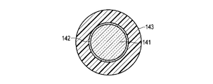
- FIG. 3A is a cross-sectional view illustrating an example of the shape of a light transmitting body.
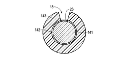
- FIG. 3B is a cross-sectional view showing the shape of another example of the light carrier.
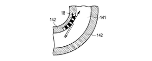
- 4A is a cross-sectional view illustrating an example of a configuration of a detection target portion in the light transmission body in FIG. 3A.
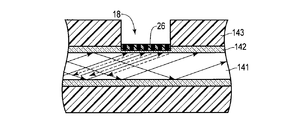
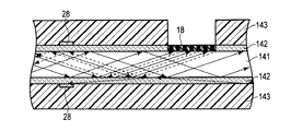
- FIG. 4B is a cross-sectional view along the longitudinal axis direction of the light transmission body of the detected portion of the light transmission body of FIG. 4A.
- FIG. 5 is a cross-sectional view along the longitudinal axis direction of the light transmission body, showing another example of the configuration of the detected portion of the light transmission body.
- FIG. 6A is a diagram illustrating an example of a grating.
- FIG. 6B is a diagram illustrating another example of the grating.
- FIG. 6C is a diagram illustrating still another example of the grating.
- FIG. 7A is a cross-sectional view showing still another example of the configuration of the detected portion in the light transmitting body.
- FIG. 7B is a diagram for explaining a modified example of the detected portion of the light transmitting body in FIG. 7A.
- FIG. 8 is a diagram for explaining the cylindrical coordinates of the light transmitting body.
- FIG. 9 is a diagram for explaining the basic principle of grating in the case of FBG (Fiber Bragg Grating).
- FIG. 10A is a diagram for explaining a diffracted wave in the FBG.
- FIG. 10B is a diagram for explaining a diffracted wave in the FBG in the case of a single mode fiber.
- FIG. 11A is a diagram for explaining a diffracted wave in the grating of the detected portion of the optical bending measuring apparatus according to the first embodiment.
- FIG. 11B is a diagram for explaining a diffracted wave in the case of a single mode fiber.
- FIG. 11C is a diagram for explaining another example of a diffracted wave in the case of a single mode fiber.
- FIG. 12A is a diagram illustrating a case where the light transmitting body is bent in the upward direction on the paper surface for explaining the operation principle of the optical bending measuring apparatus according to the first embodiment.
- FIG. 12B is a diagram illustrating a case where the light transmission body is not curved for explaining the operation principle of the optical bending measuring apparatus.
- FIG. 12C is a diagram illustrating a case where the light transmission body is bent downward in the drawing for explaining the operation principle of the optical bending measuring apparatus.
- FIG. 13 is a cross-sectional view taken along the longitudinal axis direction of the light transmission body including the clad mode removing member.
- FIG. 14A is a diagram for explaining a diffracted wave in a grating in the case of a multimode fiber as an optical bending measurement apparatus according to the second embodiment of the present invention.
- FIG. 14B is a diagram for explaining a diffracted wave in the case of a multimode fiber.
- FIG. 14C is a diagram for explaining another example of a diffracted wave in the case of a multimode fiber.
- FIG. 15 is a diagram showing a schematic configuration of an optical bending measuring apparatus according to the fourth embodiment of the present invention.
- FIG. 16 is a diagram illustrating a schematic configuration of a modified example of the optical bending measuring apparatus according to the fourth embodiment.
- FIG. 17 is a block diagram showing a schematic configuration of an endoscope as a tubular insert according to a fifth embodiment of the present invention, in which the optical bending measuring device according to the first embodiment is mounted.
- the optical bending measuring apparatus 10 includes a light source 12, a light guide member 14, a light detection unit 16, and a plurality of detected units 18 (see FIG. 1).
- the light source 12 is a light source unit that supplies measurement light.
- the light guide member 14 is a flexible light transmission body that has a core and a cladding covering the periphery thereof and a lower refractive index than the core, and transmits measurement light from the light source 12 in the longitudinal axis direction.
- the light detection unit 16 is a light detection unit that detects light output from the light guide member 14.
- the plurality of detected portions 18-1, 18-2,..., 18-n are provided so as to be in contact with the core of the light guide member 14 at a plurality of different portions in the longitudinal axis direction of the light guide member 14.
- the light branching unit 20 optically connects the light source 12 and the light detection unit 16 and one end of the light guide member 14, thereby allowing measurement light from the light source 12 to enter the one end of the light guide member 14, Light from the one end of the light guide member 14 is incident on the light detection unit 16.
- the antireflection member 22 suppresses the reflection of the measurement light so that the measurement light is reflected at the other end of the light guide member 14 and is not transmitted through the light guide member 14 in the opposite direction as much as possible.
- the antireflection member 24 suppresses the reflection of the measurement light in order to reduce the amount of the measurement light reflected by the light branching unit 20 and entering the light detection unit 16 as much as possible.
- the optical bending measuring apparatus 10 includes a light source 12, a light guide member 14, a light detection unit 16, and a plurality of detected units 18 (an example of FIG. 2). Then, it comprises two detected parts 18-1, 18-2).
- the light detection unit 16 wavelength-separates the light that has been modulated by the light having the specific wavelength caused by the gratings of the plurality of detected units 18, and the light of each separated wavelength.
- the amount of bending in the specific direction of the plurality of portions of the light guide member 14 is independently measured based on the intensity change.
- the light source 12 supplies white light having a substantially uniform light spectrum in a wide wavelength band as shown in FIG. 1, for example, as measurement light.
- the light guide member 14 can be constituted by an optical fiber, for example.
- FIG. 3A shows a radial cross-sectional structure that is a direction orthogonal to the longitudinal axis direction of the optical fiber. That is, the optical fiber includes a core 141 that guides light at the center, a clad 142 that is provided around the core 141 and stably traps light in the core 141, and the core 141 and the clad. And a jacket 143 for protecting 142 from physical shock and thermal shock.
- the light guide member 14 may be configured by an optical waveguide.
- the optical waveguide is obtained by providing a core 141 and a clad 142 that play the same role as those of the optical fiber on a flexible substrate 144.
- this optical fiber is a single mode.
- the optical fiber that is the light guide member 14 of the optical bending measuring device 10 is provided with a detected portion 18 as shown in FIGS. 4A and 4B at each portion where the amount of bending is to be measured. That is, the detected portion 18 removes the jacket 143 and the clad 142 at a desired position in the longitudinal direction of the optical fiber to expose a part of the core 141, and the exposed portion of the core 141 is exposed to a photopolymer.
- a grating 26 that is an optical property changing member is formed in a holographic manner. Note that the jacket 143 and the clad 142 are removed by laser processing or by using a photo process, an etching process, or the like. At this time, if the core 141 is scratched microscopically, light is leaked and light to be guided is lost or bending is weakened. Therefore, the core 141 is not scratched as much as possible. It is desirable to process by the method.
- the detected portion 18 is formed so that the grating 26 is in contact with the core 141. Further, the grating 26 may be formed on a part of the clad 142 as shown in FIG.
- the grating 26 causes a diffraction phenomenon when light propagates inside or is reflected by the surface, and propagates light of a specific wavelength that travels in a predetermined direction different from the incident direction to the grating 26.
- the measurement light is indicated by a solid arrow
- light of a specific wavelength that is caused to travel in a predetermined direction by the grating 26 is indicated by a dashed arrow.
- the specific wavelength can be set by the structure of the grating 26, as will be described in detail later.
- the grating 26 can be configured with a periodic structure, and the specific wavelength can be set by this period (pitch length ⁇ ).
- the refractive index of the grating 26 is smaller than the refractive index of the core 141.
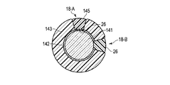
- Each detected portion may leave the grating 26 exposed as shown in FIGS. 4A, 4B, and 5, but the jacket on the grating 26 as shown in the detected portion 18-A shown in FIG. 7A.
- the jacket-like member may be filled as the detected portion protection member 145 in the portion where the 143 and the clad 142 are removed, and the original shape of the optical fiber may be recovered.
- the grating 26 may be formed so as to fill the portion from which the jacket 143 and the cladding 142 are removed, so that the original shape of the optical fiber can be recovered. .
- a plurality of detected portions 18 are provided along the longitudinal axis of the optical fiber that is the light guide member 14.
- a detected portion 18 detected portion 18-A
- Another detected part 18 detected part 18-B having a different specific wavelength may be provided in different directions of the direction axis.
- the amount of bending measured by the light detection unit 16 based on the change in light intensity is not limited to the portion where the detected portion 18 of the optical fiber is disposed, but is a predetermined length before and after the detected portion 18 is included. This is related to the measurement range. Therefore, as shown in FIG. 7B, a plurality of detected portions 18-A and 18-B may be arranged at substantially the same location on the longitudinal axis of the optical fiber so as to suppress a decrease in rigidity.
- the plurality of detected portions 18 may be provided at substantially the same location on the longitudinal axis (z axis) of the optical fiber in directions orthogonal to each other or in different directions ( ⁇ ).
- the cylindrical coordinates are as shown in FIG.
- the FBG is obtained by writing a grating 26 in a core 141 of a single mode fiber.
- the pitch length of the grating 26 is ⁇
- the wave number vectors Kin and Kout in the propagation mode are substantially directed in the z direction as described above, and therefore, the same as when the grating 26 is written in the core 141 as shown in FIG. 11B. .
- the conservation law is limited to the z direction, when kin> kG / 2, as shown in FIG. This becomes a clad mode, causing light loss and noise. If the coupling coefficient with the cladding mode is small, there is no problem, but if it is large, countermeasures are required. Since this loss occurs only when kin> kG / 2, the light of the specific wave vector Kin passes before the light of the specific wave vector Kin reaches the grating 26 as shown in FIG. 11B.
- the grating 26 may satisfy kin ⁇ kG / 2. That is, the gratings 26 are manufactured in the order in which the wave number kG does not increase from the side closer to the light source 12 (that is, the order in which the pitch length ⁇ of the grating 26 does not decrease).
- the light of the wave vector Kin does not generate a clad mode and cause a loss before reaching the grating 26 as shown in FIG. 11B.
- the generated clad mode is usually attenuated at a certain distance, so that it does not affect the other gratings 26 and the photodetection section 16.
- the light detection unit 16 is returned to.
- the detected portions 18 gratings 26
- the cross-sectional structure of the detected portions 18-1, 18-2, and 18-n is shown in FIG.
- the pitch length ⁇ of the detected portion 18-1 on the side closer to the light source 12 is short, and becomes longer as it moves away.
- light having a wavelength of ⁇ 1 to ⁇ n corresponding to the detected portions 18-1 to 18-n returns to the light detecting portion 16, and the light detecting portion 16 splits the received light. That is, the light intensity of each wavelength is detected by wavelength separation.
- This light intensity varies depending on the amount of bending (curvature) in the portion of the optical fiber in which the detected portion 18 is provided. This is because the penetration length of the evanescent wave into the clad 142 side changes depending on the incident angle to the core-clad clad interface. As shown in FIGS. 12A to 12C, the light intensity is weak if the optical fiber is bent toward the detected portion 18 side, and strong if the optical fiber is in the opposite direction (in FIGS. 12A to 12C, the intensity of the light is represented by a broken line). (Indicated by thick arrows)
- the light detection unit 16 can measure the curvature at a specific position of the optical fiber based on the intensity change of light depending on the amount of bending (curvature) at the place.
- the position is distinguished by the wave number (wavelength)
- the wave number wavelength
- gratings 26 having different wave numbers (wavelengths) in a plurality of ⁇ directions of the optical fiber curvatures in different directions determined in advance can be determined by the wave numbers (wavelengths). It can be measured with an inexpensive device.
- the gratings 26 having different wave numbers (wavelengths) for the detected portions 18 that are different in the longitudinal direction of the optical fiber it is possible to measure curvatures in different directions and positions determined in advance with an inexpensive apparatus. Therefore, the three-dimensional shape of the optical fiber can be obtained with one optical fiber.
- the grating 26 is formed by processing the clad 142 portion of the optical fiber. Therefore, a general-purpose optical fiber can be used, and the optical bending measuring apparatus 10 using the optical fiber can be produced at a low cost.
- the grating 26 In the case where the grating 26 is not manufactured in the order in which the wave number kG does not increase from the side closer to the light source 12 to the side farther from the light source 12 as described above, light having a certain wavelength is reflected before the reflection by the specific grating 26. In some cases, the loss due to the generation of the cladding mode in other gratings may occur in combination. However, this loss also depends on the curvature for the same reason as described above. Therefore, the light of the wavelength has information on the bending of a specific plurality of detected parts 18 through loss and reflection determined by the arrangement. By acquiring this information for a plurality of wavelengths, the curvature of each detected portion 18 can be solved as an inverse problem.
- the clad mode generated as described above usually attenuates at a certain distance. However, if the light detection unit 16 is reached before it is sufficiently attenuated, it becomes noise for the return light that satisfies the condition as shown in FIG. 11B. If the noise is so large that it cannot be ignored, it is necessary to form the cladding mode removal member 28 as shown in FIG.
- the clad mode removing member 28, for example, is in contact with the clad 142 and has a refractive index substantially equal to that of the clad 142 and further includes an absorbing member, or attenuates the clad mode by transmission or scattering at the interface with the outside. It is a member to be made.
- the surface (outer wall) itself of the cladding 142 may be provided with irregularities.
- the jacket 143 with good adhesion is also effective for removing the cladding mode. That is, the jacket 143 can be used as the cladding mode removal member 28.
- the clad mode removing member 28 may be formed between the light detection unit 16 and the detected unit 18 closest thereto. Since the clad mode may have an adverse effect such as being converted into another mode by another detected portion 18, it is more effective if it is formed between two adjacent detected portions 18.
- the light reflection intensity at each position can be obtained by performing spectral detection and light detection with the light detection unit 16 having a spectroscopic unit.
- the detected portion 18 since the detected portion 18 has a grating structure, there is a signal change due to the curvature in the wavelength range limited to each detected portion 18, so that the curvature at the position of each detected portion 18 is obtained. be able to.
- the refractive index of the grating 26 is smaller than the refractive index of the core 141, the main part of the waveguide mode does not enter the detected part 18 except for the evanescent component. Therefore, unnecessary light amount loss such as conversion to the clad mode does not occur.
- the refractive index of the grating 26 is smaller than the refractive index of the clad 142, all guided modes do not enter the detected portion 18 except for the evanescent component, so that unnecessary light loss is further reduced.
- the grating 26 used as the detected portion 18 has a periodic structure along the traveling direction of the optical fiber as shown in FIGS. 6A to 6C, and has a continuous refractive index due to a change in physical properties of the material or a difference in the material itself. Or it is a discontinuous periodic structure.
- the change may be a change in the refractive index of the real part or a change in the refractive index of the imaginary part. This is due to the following reason.
- Diffraction by the grating 26 is caused by the integration of periodic changes in scattering from each point on the grating 26.
- the scattering amplitude is expressed as follows (source of formula: Born, Wolff, principle of optics, 5th edition, 13.5, formula (85)).
- the scattering is not limited to Rayleigh scattering but can be expressed as a function of the complex refractive index n, and the scattering intensity can be periodically changed by the real part and the imaginary part of the refractive index.
- the grating 26 is produced holographically by, for example, a photopolymer. Since the grating 26 is manufactured not only on the surface of the photopolymer but also inside thereof, the evanescent component is efficiently bonded to the grating 26.
- the single mode light guide member 14 is used.
- the present invention can be similarly applied to the multi mode light guide member 14.
- the light intensity varies depending on the amount of bending (curvature) in the portion of the optical fiber in which the detected portion 18 is provided.
- the reason for this is that the cross-sectional distribution of the light wave density also changes in addition to the penetration length of the evanescent wave into the clad 142 side depending on the incident angle at the core-cladding clad interface, as in the case of the single mode fiber. one of.
- the reflected light has a very narrow line width.
- the pitch of the gratings 26 formed at different locations and directions of the optical fiber that is the light guide member 14 needs to be about this interval (wave number width). In that case, the number of distinguishable points is reduced, but the advantage that the multi-mode fiber is inexpensive, and the core diameter is large, so that the light source 12, the light detection unit 16, and the optical fiber can be separated. In addition, there is an advantage that the connection is simpler.
- the same device as the first embodiment is effective for the order in which the gratings 26 are arranged and the arrangement of the clad mode removing member 28. is there.
- the grating 26 can be produced holographically by a photopolymer as in the first embodiment.
- a photoresist can be used, and can be easily manufactured by a two-beam interference method, a phase mask method, or the like.
- the structure created by the photoresist may be replaced with another material, or the photoresist itself may be part of the structure.
- the refractive index of the grating 26 is smaller than the refractive index of the core 141.
- the refractive index of the grating 26 may be larger than the refractive index of the core 141.
- the refractive index of the grating 26 When the refractive index of the grating 26 is larger than the refractive index of the core 141, a part of the light component reflected by the grating surface propagates in the grating and is reflected by the outer wall of the clad 142. And becomes a reflected signal.
- the position and the curvature can be identified by the effect that the refractive index intensity varies depending on the incident angle.
- the refractive index of a part of the grating 26 is larger than the refractive index of the core 141, it is intermediate between the first embodiment and the above, and a part of the grating 26 penetrates into the clad 142. Since the first-order diffracted wave is emitted, the first-order diffracted light specifying the grating 26 is generated. Therefore, the position and curvature can be identified by the same effect as described above.
- the optical bending measuring device 10 may include a plurality of light guide members 14.
- only one light source 12 is provided in common, and a light detection unit 16 is provided for each light guide member 14.
- a light detection unit 16 is provided for each light guide member 14.
- two light detection units 16 a first light detection unit 161 and a second light detection unit 162 are provided.
- the measurement light from the light source 12 is bifurcated by an optical branching unit (not shown), and one branched measurement light is passed to one optical fiber and the optical branching unit 20 connected to the first light detection unit 161.
- the other measurement light is incident on the optical branching unit 20 connected to the other optical fiber and the second light detection unit 162.
- the detection at more positions can be performed by having the independent light detection units 16 for each of the plurality of light guide members 14.
- the light guide member 14 into which the measurement light is incident and the light guide member 14 from which the detection light is emitted may be separated from each other.
- the measurement light from the light source 12 is directly supplied to the incident-side light guide member 14, the emitted light from the incident-side light guide member 14 is reflected in two directions by the mirror 30, and each reflected light is reflected on the lens 32.
- the light is condensed and made incident on each of the light guide members 14 on the emission side.
- the detection light emitted from the emission side light guide member 14 is incident on the corresponding first light detection unit 161 or 162.
- a connecting optical fiber having an optical branching function may be used instead of the mirror 30 and the lens 32.
- the grating 26 is manufactured in the order in which the wave number kG does not increase from the side closer to the light source 12 toward the side farther. You may make it this order for every optical fiber. The reason is that the light detection unit 16 is provided independently for each optical fiber. Accordingly, in FIGS. 15 and 16, the detected portion 18-1 and the detected portion 18-2 may be the gratings 26 having the same wave number kG.
- the optical bending measuring device 10 of the present invention can be mounted on a tubular insert.
- FIG. 17 shows an endoscope system in which the light guide member 14 of the optical bending measuring apparatus 10 according to the first embodiment is installed along an insertion portion 34 of an endoscope as a tubular insert.
- the endoscope system includes an elongated insertion portion 34 that is a tubular insertion body that is inserted into a subject (for example, a body cavity (lumen)) that is an observation target, and an operation that is coupled to the proximal end portion of the insertion portion 34.
- positioned is included. Further, the endoscope system includes a controller 40 that controls the endoscope.
- the insertion portion 34 includes a distal end hard portion, a bending operation bending portion, and a flexible tube portion from the distal end side to the proximal end portion side of the insertion portion 34.
- the distal end hard portion is the distal end portion of the insertion portion 34 and is a hard member.
- An imaging unit (not shown) is provided at the hard tip portion.
- the operation bending portion bends in a desired direction according to an operation by an endoscope operator (physician or the like) of a bending operation knob provided in the operation portion 36.
- the operator bends the operation bending portion by operating the bending operation knob. Due to the bending of the operation bending portion, the position and orientation of the hard tip portion are changed, and the observation object is captured in the observation field of view that is the imaging range of the imaging unit.
- the observation object captured in this manner is irradiated with illumination light from an illumination window (not shown) provided in the hard tip portion, and the observation object is illuminated.
- the operation bending portion is configured by connecting a plurality of node rings (not shown) along the longitudinal direction of the insertion portion 34. As the node rings rotate relative to each other, the operation bending portion is bent.
- the flexible tube portion has a desired flexibility and is bent by an external force.
- the flexible tube portion is a tubular member that extends from the operation portion 36.
- connection cable 38 connects between the operation unit 36 and the controller 40.
- the controller 40 performs image processing on the observation image captured by the imaging unit of the endoscope, and displays the observation image subjected to the image processing on a display unit (not shown).
- the controller 40 includes the light source 12, the light detection unit 16, and the light branching unit 20 of the optical bending measuring device 10, and is an optical fiber as the light guide member 14. Is extended from the controller 40 along the longitudinal axis direction of the insertion portion 34 via the connection cable 38 and the operation portion 36.
- the antireflection member 22 is provided in the hard end portion of the insertion portion 34.
- the plurality of detected portions 18 are provided at positions corresponding to the operation bending portion and the flexible tube portion of the insertion portion 34 in the optical fiber.
- the light detection unit 16 can measure the bending direction and the bending amount (curvature) of a plurality of portions of the optical fiber independently of each portion. Therefore, if the number of the detected portions 18 is sufficiently large compared to the degree of deformation of the operation bending portion and the flexible tube portion of the insertion portion 34 which is the object to be measured, the bending amount and the bending direction of the insertion portion 34 are determined. And can be measured.
- the controller 40 further includes a control and calculation unit 42.
- the control and calculation unit 42 performs light emission control of the light source 12. Further, the control and calculation unit 42 calculates the three-dimensional shape of the insertion unit 34 from the bending amount and the bending direction of the optical fiber, that is, the insertion unit 34 measured by the light detection unit 16, and the obtained three-dimensional shape. Can be displayed on a display unit (not shown).
- the tubular insert is not limited to this endoscope, and may be various probes, catheters, oversheaths (tubes used for assisting insertion of endoscopes, catheters, and the like).
- DESCRIPTION OF SYMBOLS 10 ... Measuring apparatus, 12 ... Light source, 14 ... Light guide member, 141 ... Core, 142 ... Cladding, 143 ... Jacket, 144 ... Flexible substrate, 145 ... Detected part protection member, 16 ... Light detection part, 161 ... 1st , ... second detector, 18, 18-1 to 18-9, 18-n, 18-A, 18-B ... detected part, 20 ... light branching part, 22, 24 ... Antireflective member, 26 ... grating, 28 ... cladding mode removing member, 30 ... mirror, 32 ... lens, 34 ... insertion part, 36 ... operation part, 38 ... connection cable, 40 ... controller, 42 ... arithmetic part.
Landscapes
- Physics & Mathematics (AREA)
- General Physics & Mathematics (AREA)
- Optics & Photonics (AREA)
- Health & Medical Sciences (AREA)
- Life Sciences & Earth Sciences (AREA)
- Surgery (AREA)
- Engineering & Computer Science (AREA)
- Medical Informatics (AREA)
- Radiology & Medical Imaging (AREA)
- Nuclear Medicine, Radiotherapy & Molecular Imaging (AREA)
- Biophysics (AREA)
- Biomedical Technology (AREA)
- Heart & Thoracic Surgery (AREA)
- Pathology (AREA)
- Molecular Biology (AREA)
- Animal Behavior & Ethology (AREA)
- General Health & Medical Sciences (AREA)
- Public Health (AREA)
- Veterinary Medicine (AREA)
- Length Measuring Devices By Optical Means (AREA)
- Diffracting Gratings Or Hologram Optical Elements (AREA)
- Endoscopes (AREA)
Abstract
光学式曲がり測定装置(10)は、測定光を供給する光源(12)と、上記測定光をその長手軸方向に伝達する光ファイバ(14)と、上記光ファイバの上記長手軸方向に異なる複数の部分において、上記光ファイバのコアに接するように又はクラッドの一部に設けられ、それぞれ所定の方向に進む特定の波長の光を強め合うように設定したグレーティングを有する複数の被検出部(18-1,18-2,…,18-n)と、上記光ファイバから出力される光を検出する光検出部(16)と、を備える。上記光検出ユニットは、上記グレーティングにて引き起こされる上記特定の波長の光の変調を受けた光を波長分離し、各分離された波長の光の強度変化に基づいて上記光ファイバの上記複数の部分の特定方向の曲がり量を独立に測定する。
Description
本発明は、光学式曲がり測定装置及びそれを搭載した管状挿入体に関する。
G. Meltz et al.著,「Formation of Bragg gratings in optical fibers by a transverse holographic method」,(米国),Vol.14, No.15,Optics Letters,1989年8月1日,p.823-825(以下、非特許文献1と記す)は、光ファイバのコア部にグレーティングを形成することにより、ひずみや温度センシングへの光ファイバの利用ができることを述べている。
G. Meltz et al.著,「Formation of Bragg gratings in optical fibers by a transverse holographic method」,(米国),Vol.14, No.15,Optics Letters,1989年8月1日,p.823-825
上記非特許文献1には、ひずみや温度の測定について触れられているが、曲がり量の測定については何ら記載されていない。
光ファイバ等の光伝達体における複数の部分の特定方向の曲がり量を独立に測定することが望まれているが、それにグレーティングをどのように利用するかについては未だ検討がなされていない。
本発明は、上記の点に鑑みてなされたもので、グレーティングを利用して光伝達体における複数の部分の特定方向の曲がり量を独立に測定することが可能な光学式曲がり測定装置及びそれを搭載した管状挿入体を提供することを目的とする。
本発明の第1の態様によれば、測定光を供給する光源ユニットと、コアとクラッドとを有し、上記測定光をその長手軸方向に伝達する光伝達体と、上記光伝達体の上記長手軸方向に異なる複数の部分において、上記コアに接するように又は上記クラッドの一部に設けられ、それぞれ所定の方向に進む特定の波長の光を強め合うように設定したグレーティングを有する複数の被検出部と、上記光伝達体から出力される光を検出する光検出ユニットと、を具備し、上記光検出ユニットは、上記複数の被検出部のグレーティングにて引き起こされる上記特定の波長の光の変調を受けた光を波長分離し、各分離された波長の光の強度変化に基づいて上記光伝達体の上記複数の部分の特定方向の曲がり量を独立に測定する、ことを特徴とする光学式曲がり測定装置が提供される。
また、本発明の第2の態様によれば、被挿入体に挿入される管状挿入体であって、上記管状挿入体の長手軸方向に沿って、上記本発明の第1の態様による光学式曲がり測定装置の上記光伝達体を延在配置した、ことを特徴とする管状挿入体が提供される。
また、本発明の第2の態様によれば、被挿入体に挿入される管状挿入体であって、上記管状挿入体の長手軸方向に沿って、上記本発明の第1の態様による光学式曲がり測定装置の上記光伝達体を延在配置した、ことを特徴とする管状挿入体が提供される。
本発明によれば、グレーティングを利用して光伝達体における複数の部分の特定方向の曲がり量を独立に測定することが可能な光学式曲がり測定装置及びそれを搭載した管状挿入体を提供することができる。
以下、図面を参照して、本発明を実施するための形態を説明する。
[第1実施形態]
本発明の第1実施形態に係る光学式曲がり測定装置10は、図1に示すように、光源12と、導光部材14と、光検出部16と、複数の被検出部18(図1の例では、n個の被検出部18-1,18-2,…,18-9,…,18-n)と、光分岐部20と、反射防止部材22及び24と、から構成される。
本発明の第1実施形態に係る光学式曲がり測定装置10は、図1に示すように、光源12と、導光部材14と、光検出部16と、複数の被検出部18(図1の例では、n個の被検出部18-1,18-2,…,18-9,…,18-n)と、光分岐部20と、反射防止部材22及び24と、から構成される。
ここで、光源12は、測定光を供給する光源ユニットである。導光部材14は、コアとその周囲をおおう、それより屈折率が低いクラッドとを有し、光源12からの測定光をその長手軸方向に伝達する、可撓性の光伝達体である。光検出部16は、導光部材14から出力される光を検出する光検出ユニットである。複数の被検出部18-1,18-2,…,18-nは、導光部材14の長手軸方向に異なる複数の部分において、導光部材14のコアに接するように設けられた、あるいは、導光部材14のクラッドの一部に設けられた、それぞれ所定の方向に進む特定の波長の光を強め合うように設定したグレーティングを有している。光分岐部20は、光源12及び光検出部16と導光部材14の一端とを光学的に接続し、これにより、光源12からの測定光を導光部材14の上記一端に入射させると共に、導光部材14の上記一端からの光を光検出部16に入射させる。反射防止部材22は、導光部材14の他端で測定光が反射されて導光部材14を反対方向にできるだけ伝達しないように、測定光の反射を抑制する。反射防止部材24は、光分岐部20で測定光が反射されて光検出部16に入射する量をできるだけ減らすため、測定光の反射を抑制する。
なお、図1の構成は、光源12と光検出部16が導光部材14の同じ側にある場合であるが、光源12と光検出部16とが導光部材14に対し違う側にあっても構わない。この場合、本実施形態に係る光学式曲がり測定装置10は、図2に示すように、光源12と、導光部材14と、光検出部16と、複数の被検出部18(図2の例では、2個の被検出部18-1,18-2)と、から構成される。
そして、本実施形態では、光検出部16は、上記複数の被検出部18のグレーティングにて引き起こされる上記特定の波長の光の変調を受けた光を波長分離し、各分離された波長の光の強度変化に基づいて上記導光部材14の上記複数の部分の上記特定方向の曲がり量を独立に測定する。
以下、各部の構成について、詳細に説明する。
光源12は、測定光として、例えば図1中に示すような広範囲の波長帯域の間で略均一な光スペクトルを有する白色光を供給する。
導光部材14は、例えば、光ファイバによって構成されることができる。図3Aは、この光ファイバの長手軸方向に直交する方向である径方向の断面構造を示している。すなわち、上記光ファイバは、中心に存在する、光を導光するコア141と、当該コア141の周りに設けられた、光を安定的にコア141に閉じ込めるクラッド142と、更にこれらコア141及びクラッド142を物理的な衝撃及び熱的な衝撃から保護するためのジャケット143と、によって構成されている。
あるいは、導光部材14は、光導波路によって構成されても良い。光導波路は、図3Bに示すように、フレキシブル基板144上に、上記光ファイバのそれらと同等の役割をするコア141とクラッド142とを設けたものである。
以下、導光部材14を上記のような光ファイバによって構成した場合を例に取って、光学式曲がり測定装置10の構成を更に詳しく説明する。なお、本実施形態では、この光ファイバは、シングルモードである。
光学式曲がり測定装置10の導光部材14である光ファイバは、曲がり量を測定するべきそれぞれの部分に、図4A及び図4Bに示すような被検出部18が設けられている。すなわち、被検出部18は、光ファイバの長手軸方向の所望位置において、ジャケット143とクラッド142を除去してコア141の一部を露出させ、この露出させたコア141の部分に、フォトポリマーによりホログラフィックに光学特性変化部材であるグレーティング26を形成したものである。なお、上記ジャケット143及び上記クラッド142の除去は、レーザ加工によって、あるいは、フォト工程及びエッチング工程などを利用して行う。このとき、上記コア141にミクロな傷を付けてしまうと、光を漏らし、導光する光を損失させてしまったり、曲げに弱くなったりしたりするので、上記コア141に極力傷を付けない方法で加工することが望ましい。
このように、被検出部18は、グレーティング26をコア141に接触するように形成したものである。また、グレーティング26は、接触していなくても、図5に示すように、クラッド142の一部に形成されていても良い。
グレーティング26は、光が内部を伝搬または表面で反射するときに回折現象を起こして、当該グレーティング26への入射方向とは異なる所定の方向に進む特定の波長の光を強め合うように伝搬させる。図4Bでは、測定光を実線の矢印で示し、グレーティング26によって所定方向に進むようにされた特定波長の光を破線の矢印で示している。
なお、上記特定の波長は、詳細は後述するように、グレーティング26の構造によって設定することが可能となっている。例えば、図6A乃至図6Cに示すように、グレーティング26を周期性を持つ構造により構成することができ、この周期(ピッチ長Λ)によって、上記特定の波長を設定することができる。
なお、本実施形態では、グレーティング26の屈折率は、コア141の屈折率よりも小さいものとする。
なお、各被検出部は、図4A及び図4B、及び図5のようにグレーティング26を剥き出しのままとしても良いが、図7Aに示す被検出部18-Aのように、グレーティング26上のジャケット143とクラッド142とを除去した部分に対してジャケット様の部材を被検出部保護部材145として満たして、光ファイバの元の形状に回復させても良い。あるいは、図7Aに示す被検出部18-Bのように、ジャケット143とクラッド142を除去した部分を満たすように、グレーティング26を形成することで、光ファイバの元の形状に回復させても良い。
図1及び図2では、導光部材14である光ファイバの長手軸に沿って複数の被検出部18を設けている。このように並べて配置するだけで無く、図7Aに示すように、一つの被検出部18(被検出部18-A)に対して、光ファイバの長手軸の同じ箇所で、直交方向に或いは径方向の軸が異なる向きに、異なる特定の波長を持つもう一つの被検出部18(被検出部18-B)を設けても良い。この構造では、被検出部18-A,18-Bに対応する部分での曲がり量だけではなく、湾曲の方向も測定可能となる。
また、光ファイバの長手軸の同じ箇所に複数の被検出部18-A,18-Bを配置すると、当該箇所の剛性が低下し、曲げに弱くなってしまう。一方、光検出部16によって光の強度変化に基づいて測定される曲がり量は、光ファイバの上記被検出部18が配された部分だけではなく、上記被検出部18を含めた前後所定の長さの測定範囲に関するものである。そのため、図7Bに示すように、光ファイバの長手軸の略同じ箇所に複数の被検出部18-A,18-Bを配置するようにして、剛性低下を抑制するようにしても構わない。
このように、複数の被検出部18を、光ファイバの長手軸(z軸)の略同じ箇所に互いに直交方向やφが異なる向きに設けても良い(なお、導光部材14である光ファイバの円筒座標は、図8に示す通りである)。複数の被検出部18を異なるz方向位置及びφ方向位置上に作製することで、様々な位置での様々な方向の曲率(曲がりの度合い)を検出することができる。
以下、被検出部18のグレーティング26の原理説明を行う。説明の都合上、既存技術であるFBG(Fiber Bragg Grating)の場合のグレーティング26の基本原理から説明する。
FBGは、図9に示すように、シングルモードファイバのコア141にグレーティング26を書き込んだものである。グレーティング26のピッチ長をΛとしたときに、グレーティング26によって(真空中の)波長λB=2nΛの光が選択的に反射される(nはコア141の屈折率)。
これは、波長λの逆数である波数kを使って考えると、以下のようになる。
波長λと波数kの関係をk=2π/λとする。1次回折は、大きさkを持ち、かつ、波の進行方向の向きを持つ、波数ベクトルK(本明細書において、大文字のKはベクトルであることを表す)の保存則として、下記のように説明できる。
波長λと波数kの関係をk=2π/λとする。1次回折は、大きさkを持ち、かつ、波の進行方向の向きを持つ、波数ベクトルK(本明細書において、大文字のKはベクトルであることを表す)の保存則として、下記のように説明できる。
図10Aに示すように、コア141の中では、波数ベクトルKinの波は、グレーティング26の波数ベクトルKG(KG=2π/Λ)の1次回折で、Kout=Kin+KGという波数ベクトルKoutの波を発生させる。シングルモードファイバでは、伝搬モードの波数ベクトルKin,Koutは、ほぼz方向を向いている。また、回折により波数の大きさは変わらないので、kin=koutである。
この2条件を満たすのは、図10Bに示すように、(コア141中の)入射波数kin=2π/(2Λ)、グレーティング26の波数kG=2π/Λのときであり、このときだけシングルモードファイバを逆方向に伝搬する回折波を出すことができる。
本実施形態のようにクラッド142にグレーティング26がある場合も、コア-クラッドクラッド界面に入射した光は上記と同様な回折を起こすために、その位置のグレーティング26の1次回折光を反射する。ただし、回折は主にコア-クラッド界面で起こるため、波数の保存則は、上記のようなKout=Kin+KGではなく、図11Aに示すように、表面に沿った方向、すなわちz成分の保存則になる。これは、kout,z=kin,z+kGと書くことができる。シングルモードファイバでは、前述のように伝搬モードの波数ベクトルKin,Koutはほぼz方向を向いているので、図11Bに示すように、上記のコア141にグレーティング26を書き込んだ場合と同じことになる。
ただし、保存則がz方向に限定されるため、kin>kG/2の場合には、図11Cに示すように、直進しないモードとカップルする可能性がある。これはクラッドモードになり、光の損失、ノイズの原因になる。クラッドモードとのカップリング係数が小さければ問題ないが、大きい場合は、対策が必要である。この損失は、kin>kG/2の場合だけ発生するため、特定の波数ベクトルKinの光が図11Bのようになるグレーティング26に到達するよりも前にその特定の波数ベクトルKinの光が通過するグレーティング26は、kin<kG/2を満たせばよい。つまり、光源12に近い側から遠い側に向かって、波数kGが長くならない順番(すなわち、グレーティング26のピッチ長Λが短くならない順番)にグレーティング26を作製する。
このようにすれば、図11Bのようになるグレーティング26に到達する前に波数ベクトルKinの光がクラッドモードを発生して損失を起こすことがなくなる。発生したクラッドモードは通常、ある程度の距離で減衰するので、他のグレーティング26や光検出部16に影響を及ぼすことはない。
従って、導光部材14である光ファイバの特定の被検出部18に対して特定の波数ベクトルKinがあり、図1の構成では、同じ大きさの逆方向の光が、光分岐部20を介して光検出部16に戻ることになる。特に上述の順番で被検出部18(グレーティング26)を並べた例として、図1中に、被検出部18-1,18-2,18-nの断面構造を示している。グレーティング26は光源12に近い側の被検出部18-1のピッチ長Λが短く、遠ざかると長くなる。図1中に示すように、被検出部18-1~18-nに対応したλ1~λnの波長の光が光検出部16に戻り、光検出部16では、この受光した光を分光する、つまり波長分離して、それぞれの波長の光の光強度を検出する。
この光強度は、その被検出部18が設けられた光ファイバの部分での曲がり量(曲率)によって変化する。これは、コア-クラッドクラッド界面への入射角により、エバネッセント波のクラッド142側への侵入長が変化するからである。図12A乃至図12Cに示すように、被検出部18側に光ファイバが曲がっていれば光強度は弱く、それと逆方向ならば強くなる(図12A乃至図12Cでは、光強度の強弱を、破線矢印の太細により表している)。
従って、光検出部16は、その場所での曲がり量(曲率)に依存する光の強度変化に基づいて、光ファイバの特定の位置での曲率を測定することができる。
このように、波数(波長)により位置を区別するので、光源12及び光検出部16として特別な構成のものを用意する必要がなく、光学式曲がり測定装置10を安価に構成することができる。
また、図7A及び図7Bに示したように、光ファイバの複数のφ方向に、互いに異なる波数(波長)のグレーティング26を形成することで、あらかじめ定まった異なる方向の曲率を波数(波長)により安価な装置で測定することができる。同時に、光ファイバの長手軸方向に異なる被検出部18も異なる波数(波長)のグレーティング26を形成することにより、あらかじめ定まった異なる方向、位置の曲率を安価な装置で測定することができる。従って、1本の光ファイバで、光ファイバの3次元的な形状を求めることができる。
また、本実施形態では、光ファイバのクラッド142部分を加工してグレーティング26を形成する方式である。そのため、汎用品の光ファイバを利用することができ、安価に光ファイバを利用した光学式曲がり測定装置10を作成することができる。
このような長所は、本発明の他の実施の形態にも共通している。
なお、上述のような光源12に近い側から遠い側に向かって波数kGが長くならない順番にグレーティング26を作製しなかった場合には、ある波長の光は特定のグレーティング26での反射の手前で、他のグレーティングでのクラッドモード発生による損失が複合的に生じることがある。しかしながら、この損失も上記と同様な理由で曲率に依存する。従って、その波長の光は、並べ方により定まる損失と反射を通じて、特定の複数の被検出部18の曲がりの情報を持つ。複数波長についてこの情報を取得することで、それぞれの被検出部18の曲率を逆問題として解くことが可能である。
また、前述したように発生したクラッドモードは通常、ある程度の距離で減衰する。しかし、十分減衰する前に光検出部16に到達すると、図11Bようになる条件を満たす戻り光に対してノイズとなる。そのノイズが無視できないくらい大きい場合は、図13に示すように、クラッドモード除去部材28を形成する必要がある。このクラッドモード除去部材28は、例えば、クラッド142に接触して、屈折率がほぼクラッド142と同等で、吸収部材をさらに含む部材、あるいは、外界との界面での透過又は散乱によりクラッドモードを減衰させる部材、である。このクラッドモード除去部材28としては、クラッド142の表面(外壁)そのものに凹凸を付けただけであってもよい。密着性がよいジャケット143も、クラッドモードの除去に有効である。すなわち、ジャケット143をクラッドモード除去部材28として利用することができる。
クラッドモード除去部材28は、光検出部16とそれに最も近い被検出部18との間に形成するとよい。クラッドモードは、他の被検出部18でさらに別のモードに変換される等の悪影響を及ぼすおそれがあるので、隣接する2つの被検出部18の間にも形成すると、より効果的である。
このようにすれば、クラッドモードが残存するような状況でも、図1の構成では、各位置のグレーティング26に特有な波数の光だけが戻る。よって、分光部をもつ光検出部16で分光して光検出することにより、各位置での光の反射強度を求めることができる。
なお、図2の構成では、各位置(被検出部18-1,18-2)で特有の波数が反射された後のディップが観察される(λ1、λ2)。このディップの深さも曲率によって変化する。上述のクラッドモードへのカップリングがあまり大きくない場合は、この図2の構成も可能である。
いずれにしても、被検出部18をグレーティング構造とすることで、各被検出部18毎に限定された波長範囲で曲率による信号変化があるため、各被検出部18の位置での曲率を得ることができる。
しかも、グレーティング26の屈折率がコア141の屈折率よりも小さいため、導波モードの主要部はエバネッセント成分を除いて被検出部18に侵入することがない。よって、クラッドモードへの変換等の不要な光量損失が生じない。
グレーティング26の屈折率がクラッド142の屈折率よりも小さいと、全ての導波モードはエバネッセント成分を除いて被検出部18に侵入することがないので、不要な光量損失がさらに減少する。
被検出部18として利用するグレーティング26は、図6A乃至図6Cのように、光ファイバの進行方向に沿った周期構造であり、材料の物性等の変化または材料そのものの違いによる屈折率の連続的または不連続的な周期構造である。変化は、実部の屈折率変化でも、虚部の屈折率変化でもよい。これは以下の理由による。グレーティング26による回折は、グレーティング26の各点からの散乱の周期的変化の積分により引き起こされる。散乱は、例えばレイリー散乱の場合では、散乱振幅は以下のように表される(式の出典:ボルン、ウルフ著,光学の原理,第5版,13.5,(85)式)。

このように、散乱は、レイリー散乱に限らず、複素屈折率nの関数として表すことができ、屈折率の実部によっても虚部によっても散乱強度を周期的に変化させることができる。
なお、グレーティング26は、例えばフォトポリマーによりホログラフィックに作製される。グレーティング26は、フォトポリマーの表面だけでなく、その内部まで作製されるので、エバネッセント成分がグレーティング26に効率よく結合する。
[第2実施形態]
上記第1実施形態では、シングルモードの導光部材14の場合であったが、本発明は、マルチモードの導光部材14であっても、同様に適用可能である。
上記第1実施形態では、シングルモードの導光部材14の場合であったが、本発明は、マルチモードの導光部材14であっても、同様に適用可能である。
マルチモードファイバの場合も、光強度は、その被検出部18が設けられた光ファイバの部分での曲がり量(曲率)によって変化する。これは、シングルモードファイバと同様に、コア-クラッドクラッド界面への入射角により、エバネッセント波のクラッド142側への侵入長が変化することに加えて、光波密度の断面分布も変化することも理由の一つである。
シングルモードファイバでは、反射光は非常に狭い線幅を持つ。これに対して、マルチモードファイバでは、多くのモードがあるため、1個のグレーティング26に対して反射する波長は幅のある帯域を持つ。波数ベクトルKGのグレーティング26に対して、図14Aに示すようなコア141中の波数kin=kG/2から図14Bに示すような波数kin=kG/(2cosθR)の波数範囲で反射が起こる(真空中の波長で2nΛcosθR<λ<2nΛ)。ここで、θRはsinθR=NA/nを満たすファイバ内での伝搬モードの臨界角、nはコア141の屈折率、NAはファイバの開口数、である。
従って、導光部材14である光ファイバの異なる場所及び方向に形成するグレーティング26のピッチは、この間隔(波数の幅)程度あける必要がある。そのぶん、区別可能な点数が減少するが、マルチモードファイバは安価であるという長所、さらには、コア径が大きいため、光源12及び光検出部16と光ファイバとを切り離し可能な構成とした場合に、接続がより簡便であるという長所がある。
図14Cのようなクラッドモードへの変換の問題も、シングルモードファイバと共通なので、グレーティング26を並べる順序、クラッドモード除去部材28の配置については、上記第1実施形態と同様な工夫が効果的である。
なお、グレーティング26は、第1実施形態と同様、フォトポリマーによりホログラフィックに作製されることができる。また、フォトレジストを利用することもでき、2光束干渉法、位相マスク法などにより簡便に製作することができる。フォトレジストによって作成した構造を他の材料で置換してもよく、フォトレジスト自体を構造の一部としてもよい。
[第3実施形態]
上記第1実施形態では、グレーティング26の屈折率がコア141の屈折率よりも小さいものとしたが、グレーティング26の屈折率をコア141の屈折率よりも大きくしてもよい。
上記第1実施形態では、グレーティング26の屈折率がコア141の屈折率よりも小さいものとしたが、グレーティング26の屈折率をコア141の屈折率よりも大きくしてもよい。
グレーティング26の屈折率がコア141の屈折率よりも大きい場合は、グレーティング面で反射する光成分の一部はグレーティング内を伝搬し、クラッド142の外壁で反射するが、その過程で1次回折して反射信号になる。屈折率の強度が入射角によって変化する等の効果により、屈折率がコア141より小さい場合と同様、位置及び曲率を識別することができる。
また、グレーティング26の一部の屈折率がコア141の屈折率よりも大きい場合は、第1実施形態と上記との中間的になり、一部がクラッド142内に侵入するが、上記と同様に1次回折波が出るため、グレーティング26を特定する1次回折光が発生する。従って、上記と同様な効果により、位置及び曲率を識別することができる。
[第4実施形態]
光学式曲がり測定装置10は、導光部材14を複数本備えていてもよい。
光学式曲がり測定装置10は、導光部材14を複数本備えていてもよい。
この場合、光源12は共通として1個だけ備え、導光部材14毎に光検出部16を設ける。例えば、図15に示すように、導光部材14である光ファイバを2本備える場合、第1の光検出部161と第2の光検出部162との2個の光検出部16を設ける。そして、光源12からの測定光を図示しない光分岐部にて2分岐して、分岐された一方の測定光を一方の光ファイバと第1の光検出部161に接続された光分岐部20に入射させ、他方の測定光を他方の光ファイバと第2の光検出部162に接続された光分岐部20に入射させる。
このように、複数の導光部材14それぞれに対して独立した光検出部16を持つことで、より多くの位置での検出ができる。
また、図16に示すように、測定光が入射される導光部材14と検出光が出射される導光部材14とを分離して構成としてもよい。この場合、光源12からの測定光は直接、入射側の導光部材14に供給され、この入射側導光部材14からの出射光をミラー30で2方向に反射させ、各反射光をレンズ32で集光して、出射側の導光部材14のそれぞれに入射させる。そして、これら出射側導光部材14から出射される検出光を、対応する第1の光検出部161又は162に入射させる。
この構成では、光源12と光検出部16との間の分岐(光分岐部20)が無くなるため、光の利用効率が高い。
なお、ミラー30とレンズ32の代わりに、光分岐機能を持った接続用光ファイバを用いても良い。
図15の導光部材14及び図16の出射側導光部材14は、2本の場合を例に説明したが、より多くの本数にも拡張可能なことは勿論である。その本数に応じて、より多くの位置での検出ができる。
また、図15及び図16では、2本の光ファイバを1本と想定して、光源12に近い側から遠い側に向かって波数kGが長くならない順番にグレーティング26を作製したものとしているが、光ファイバ毎にこの順番となるようにしても構わない。その理由は、光検出部16が光ファイバ毎に独立して設けられているからである。従って、図15及び図16において、被検出部18-1と被検出部18-2とが同じ波数kGのグレーティング26であってもよい。
[第5実施形態]
本発明の光学式曲がり測定装置10は、管状挿入体に搭載することができる。
本発明の光学式曲がり測定装置10は、管状挿入体に搭載することができる。
例えば、図17は、第1実施形態に係る光学式曲がり測定装置10の導光部材14を、管状挿入体としての内視鏡の挿入部34に沿って設置した内視鏡システムを示している。この内視鏡システムは、観察対象物である被検体(例えば体腔(管腔))内に挿入される管状挿入体である細長い挿入部34と、該挿入部34の基端部と連結した操作部36と、接続ケーブル38と、が配設される内視鏡を含む。さらに、内視鏡システムは、内視鏡を制御するコントローラ40を含んでいる。
ここで、挿入部34は、挿入部34の先端部側から基端部側に向かって、先端硬質部と、湾曲する操作湾曲部と、可撓管部と、を有している。先端硬質部は、挿入部34の先端部であり、硬い部材となっている。この先端硬質部には、図示しない撮像部が設けられている。
操作湾曲部は、操作部36に設けられた湾曲操作ノブの内視鏡オペレータ(医師らの作業者)による操作に応じて、所望の方向に湾曲する。オペレータは、この湾曲操作ノブを操作することで、操作湾曲部を湾曲させる。この操作湾曲部の湾曲により、先端硬質部の位置と向きが変えられ、観察対象物が撮像部の撮像範囲である観察視野内に捉えられる。こうして捉えられた観察対象物に対し、先端硬質部に設けられた図示しない照明窓から照明光が照射されて、観察対象物が照明させる。操作湾曲部は、図示しない複数個の節輪が挿入部34の長手方向に沿って連結されることにより、構成される。節輪同士が互いに対して回動することで、操作湾曲部は湾曲する。
可撓管部は、所望な可撓性を有しており、外力によって曲がる。可撓管部は、操作部36から延出されている管状部材である。
接続ケーブル38は、操作部36とコントローラ40との間を接続している。
コントローラ40は、内視鏡の撮像部により撮像された観察画像に対して画像処理を施し、図示しない表示部に画像処理された観察画像を表示させる。そして、本実施形態では、図17に示すように、このコントローラ40に、光学式曲がり測定装置10の光源12、光検出部16及び光分岐部20を内蔵させ、導光部材14である光ファイバを、このコントローラ40から接続ケーブル38及び操作部36内を経由して、挿入部34の長手軸方向に沿って延在配置する。反射防止部材22は、挿入部34の先端硬質部内に設ける。この場合、複数の被検出部18は、光ファイバの内、挿入部34の操作湾曲部及び可撓管部内に対応する位置に設けられる。
前述したように、光検出部16は、光ファイバの複数の部分の湾曲方向と曲がり量(曲率)を、各部分独立に測定することができる。従って、被検出部18の個数が被測定物である挿入部34の操作湾曲部及び可撓管部の変形の度合いに比べて十分多数形成されていれば、挿入部34の曲がり量と湾曲方向とを測定することができる。
コントローラ40は、さらに、制御及び演算部42を備えている。この制御及び演算部42は、光源12の発光制御を行う。さらに、制御及び演算部42は、光検出部16が測定した光ファイバつまり挿入部34の曲がり量と湾曲方向とから、挿入部34の3次元的形状を演算し、得られた3次元的形状を図示しない表示部に表示することができる。
なお、管状挿入体は、この内視鏡に限定するものではなく、各種プローブ、カテーテル、オーバーシース(内視鏡やカテーテル等を挿入する際の補助に使う管)、などであってもよい。
以上、実施形態に基づいて本発明を説明したが、本発明は、上述した実施形態に限定されるものではなく、本発明の要旨の範囲内で種々の変形や応用が可能なことは勿論である。
例えば、被検出部18が複数構成されるものとして説明してきたが、1箇であっても構わない。
10…測定装置、 12…光源、 14…導光部材、 141…コア、 142…クラッド、 143…ジャケット、 144…フレキシブル基板、 145…被検出部保護部材、 16…光検出部、 161…第1の光検出器、 162…第2の光検出器、 18,18-1~18-9,18-n,18-A,18-B…被検出部、 20…光分岐部、 22,24…反射防止部材、 26…グレーティング、 28…クラッドモード除去部材、 30…ミラー、 32…レンズ、 34…挿入部、 36…操作部、 38…接続ケーブル、 40…コントローラ、 42…演算部。
Claims (20)
- 測定光を供給する光源ユニットと、
コアとクラッドとを有し、上記測定光をその長手軸方向に伝達する光伝達体と、
上記光伝達体の上記長手軸方向に異なる複数の部分において、上記コアに接するように又は上記クラッドの一部に設けられ、それぞれ所定の方向に進む特定の波長の光を強め合うように設定したグレーティングを有する複数の被検出部と、
上記光伝達体から出力される光を検出する光検出ユニットと、
を具備し、
上記光検出ユニットは、上記複数の被検出部のグレーティングにて引き起こされる上記特定の波長の光の変調を受けた光を波長分離し、各分離された波長の光の強度変化に基づいて上記光伝達体の上記複数の部分の特定方向の曲がり量を独立に測定する、ことを特徴とする光学式曲がり測定装置。 - 上記グレーティングは、光が内部を伝搬または表面で反射するときに回折現象を起こして上記所定の方向に光を伝搬させる、周期性を持つ構造を有する、ことを特徴とする請求項1に記載の光学式曲がり測定装置。
- 上記グレーティングは、屈折率の実部の周期的変化を含む、ことを特徴とする請求項2に記載の光学式曲がり測定装置。
- 上記グレーティングは、屈折率の虚部の周期的変化を含む、ことを特徴とする請求項2に記載の光学式曲がり測定装置。
- 上記グレーティングの屈折率の実部は、上記光伝達体の上記コアの屈折率よりも小さい、ことを特徴とする請求項2に記載の光学式曲がり測定装置。
- 上記グレーティングの屈折率の実部は、上記光伝達体の上記クラッドの屈折率よりも小さい、ことを特徴とする請求項2に記載の光学式曲がり測定装置。
- 上記グレーティングの屈折率の実部は、上記光伝達体の上記コアの屈折率よりも大きい、ことを特徴とする請求項2に記載の光学式曲がり測定装置。
- 上記光伝達体は、シングルモードの光ファイバである、ことを特徴とする請求項2に記載の光学式曲がり測定装置。
- 上記光伝達体は、マルチモードの光ファイバである、ことを特徴とする請求項2に記載の光学式曲がり測定装置。
- 上記グレーティングは、フォトポリマーにより形成される、ことを特徴とする請求項2に記載の光学式曲がり測定装置。
- 上記グレーティングは、フォトレジストにより形成される、ことを特徴とする請求項2に記載の光学式曲がり測定装置。
- 上記複数の被検出部はそれぞれ、上記光伝達体の上記長手軸まわりの上記特定の方向を中心とする一部に形成される、ことを特徴とする請求項2に記載の光学式曲がり測定装置。
- 上記複数の被検出部の内の一部は、上記光伝達体の上記長手軸まわりの上記特定の方向を中心とする一部に形成され、上記複数の被検出部の内の他の一部は、上記光伝達体の上記長手軸まわりの上記特定の方向とは異なる第2の特定の方向を中心とする一部に形成され、
上記特定の方向を中心とする一部に形成された上記一部の被検出部の内、1個の上記グレーティングの上記周期性を持つ構造は、上記第2の特定の方向を中心とする一部に形成された上記一部の被検出部の内の1個の上記グレーティングの上記周期性を持つ構造と異なる周期を有する、ことを特徴とする請求項2に記載の光学式曲がり測定装置。 - 上記特定の方向を中心とする一部に形成された上記一部の被検出部それぞれの上記グレーティングの上記周期性を持つ構造は、上記第2の特定の方向を中心とする一部に形成された上記一部の被検出部それぞれの上記グレーティングの上記周期性を持つ構造と異なる周期を有する、ことを特徴とする請求項13に記載の光学式曲がり測定装置。
- 上記複数の被検出部は、上記グレーティングの上記周期性を持つ構造が、上記光源ユニットに近い側から遠い側に向かって、周期が短くならない方向の順番で並ぶように、上記光伝達体に設けられる、ことを特徴とする請求項2に記載の光学式曲がり測定装置。
- 上記光源ユニットと上記光検出ユニットは、上記光伝達体に対して同じ側にある、ことを特徴とする請求項15に記載の光学式曲がり測定装置。
- 上記光源ユニットと上記複数の被検出部との間に設けられたクラッドモード除去部材を更に具備する、ことを特徴とする請求項2に記載の光学式曲がり測定装置。
- 上記複数の被検出部間に設けられたクラッドモード除去部材を更に具備する、ことを特徴とする請求項2に記載の光学式曲がり測定装置。
- 上記光検出ユニットによって波長分離される光は、上記複数の被検出部のグレーティングにて複合的に引き起こされる上記特定の波長の光の光強度の変化を受けた光である、請求項1乃至18の何れかに記載の光学式曲がり測定装置。
- 被挿入体に挿入される管状挿入体であって、
上記管状挿入体の長手軸方向に沿って、請求項1乃至19の何れかに記載の光学式曲がり測定装置の上記光伝達体を延在配置した、ことを特徴とする管状挿入体。
Priority Applications (3)
| Application Number | Priority Date | Filing Date | Title |
|---|---|---|---|
| JP2017505776A JP6413011B2 (ja) | 2015-03-13 | 2015-03-13 | 光学式曲がり測定装置及び管状挿入体 |
| PCT/JP2015/057519 WO2016147261A1 (ja) | 2015-03-13 | 2015-03-13 | 光学式曲がり測定装置及び管状挿入体 |
| US15/701,551 US10401140B2 (en) | 2015-03-13 | 2017-09-12 | Bending detecting system, light guide body, tubular apparatus, light detecting apparatus, light detecting method, and optical bending measuring apparatus |
Applications Claiming Priority (1)
| Application Number | Priority Date | Filing Date | Title |
|---|---|---|---|
| PCT/JP2015/057519 WO2016147261A1 (ja) | 2015-03-13 | 2015-03-13 | 光学式曲がり測定装置及び管状挿入体 |
Related Child Applications (1)
| Application Number | Title | Priority Date | Filing Date |
|---|---|---|---|
| US15/701,551 Continuation-In-Part US10401140B2 (en) | 2015-03-13 | 2017-09-12 | Bending detecting system, light guide body, tubular apparatus, light detecting apparatus, light detecting method, and optical bending measuring apparatus |
Publications (1)
| Publication Number | Publication Date |
|---|---|
| WO2016147261A1 true WO2016147261A1 (ja) | 2016-09-22 |
Family
ID=56918548
Family Applications (1)
| Application Number | Title | Priority Date | Filing Date |
|---|---|---|---|
| PCT/JP2015/057519 Ceased WO2016147261A1 (ja) | 2015-03-13 | 2015-03-13 | 光学式曲がり測定装置及び管状挿入体 |
Country Status (3)
| Country | Link |
|---|---|
| US (1) | US10401140B2 (ja) |
| JP (1) | JP6413011B2 (ja) |
| WO (1) | WO2016147261A1 (ja) |
Cited By (1)
| Publication number | Priority date | Publication date | Assignee | Title |
|---|---|---|---|---|
| JP2019531487A (ja) * | 2016-08-10 | 2019-10-31 | フラウンホファー ゲセルシャフト ツール フェールデルンク ダー アンゲヴァンテン フォルシュンク エー.ファオ. | 光学導波路の屈曲及び/またはひずみを決定するための方法 |
Families Citing this family (4)
| Publication number | Priority date | Publication date | Assignee | Title |
|---|---|---|---|---|
| CN110095086B (zh) * | 2019-06-03 | 2024-06-07 | 呜啦啦(广州)科技有限公司 | 电流式双向弯曲传感器及其制备方法 |
| CN114631002B (zh) * | 2019-10-31 | 2024-09-27 | 欧特尼斯有限公司 | 用于测量三维曲线形状的特殊光纤及其制造方法、及利用特殊光纤测量三维曲线形状的系统 |
| US11467336B1 (en) * | 2021-04-29 | 2022-10-11 | General Dynamics Mission Systems, Inc. | Fiber optic switch employing moveable structure interaction with the evanescent field of a cladding-removed fiber |
| US12222549B2 (en) * | 2021-10-21 | 2025-02-11 | Gyrus Acmi, Inc. | Endoscope including fiber delivery of illumination light |
Citations (4)
| Publication number | Priority date | Publication date | Assignee | Title |
|---|---|---|---|---|
| JPH0219730A (ja) * | 1988-07-07 | 1990-01-23 | Mitsubishi Electric Corp | 光ファイバ温度センサ |
| US20070297712A1 (en) * | 2006-06-08 | 2007-12-27 | Chiara Meneghini | Optical fiber sensor and method |
| JP2010104427A (ja) * | 2008-10-28 | 2010-05-13 | Olympus Medical Systems Corp | 医療機器 |
| JP2013036925A (ja) * | 2011-08-10 | 2013-02-21 | Olympus Corp | ファイバーセンサー |
Family Cites Families (5)
| Publication number | Priority date | Publication date | Assignee | Title |
|---|---|---|---|---|
| US6275628B1 (en) * | 1998-12-10 | 2001-08-14 | Luna Innovations, Inc. | Single-ended long period grating optical device |
| US6854327B2 (en) * | 2002-11-06 | 2005-02-15 | Shell Oil Company | Apparatus and method for monitoring compaction |
| US7539361B2 (en) * | 2006-10-05 | 2009-05-26 | Harris Corporation | Fiber optic device for measuring a parameter of interest |
| US8554024B2 (en) * | 2006-10-25 | 2013-10-08 | Lxdata Inc. | Tilted grating sensor |
| US8009946B2 (en) * | 2008-01-22 | 2011-08-30 | General Electric Company | Fiberoptic patient health multi-parameter monitoring devices and system |
-
2015
- 2015-03-13 JP JP2017505776A patent/JP6413011B2/ja active Active
- 2015-03-13 WO PCT/JP2015/057519 patent/WO2016147261A1/ja not_active Ceased
-
2017
- 2017-09-12 US US15/701,551 patent/US10401140B2/en active Active
Patent Citations (4)
| Publication number | Priority date | Publication date | Assignee | Title |
|---|---|---|---|---|
| JPH0219730A (ja) * | 1988-07-07 | 1990-01-23 | Mitsubishi Electric Corp | 光ファイバ温度センサ |
| US20070297712A1 (en) * | 2006-06-08 | 2007-12-27 | Chiara Meneghini | Optical fiber sensor and method |
| JP2010104427A (ja) * | 2008-10-28 | 2010-05-13 | Olympus Medical Systems Corp | 医療機器 |
| JP2013036925A (ja) * | 2011-08-10 | 2013-02-21 | Olympus Corp | ファイバーセンサー |
Cited By (2)
| Publication number | Priority date | Publication date | Assignee | Title |
|---|---|---|---|---|
| JP2019531487A (ja) * | 2016-08-10 | 2019-10-31 | フラウンホファー ゲセルシャフト ツール フェールデルンク ダー アンゲヴァンテン フォルシュンク エー.ファオ. | 光学導波路の屈曲及び/またはひずみを決定するための方法 |
| JP6997186B2 (ja) | 2016-08-10 | 2022-01-17 | フラウンホファー ゲセルシャフト ツール フェールデルンク ダー アンゲヴァンテン フォルシュンク エー.ファオ. | 光学導波路の屈曲及び/またはひずみを決定するための方法 |
Also Published As
| Publication number | Publication date |
|---|---|
| JP6413011B2 (ja) | 2018-10-24 |
| US10401140B2 (en) | 2019-09-03 |
| JPWO2016147261A1 (ja) | 2018-03-08 |
| US20170370697A1 (en) | 2017-12-28 |
Similar Documents
| Publication | Publication Date | Title |
|---|---|---|
| JP6413011B2 (ja) | 光学式曲がり測定装置及び管状挿入体 | |
| US6868195B2 (en) | Device for detecting three-dimensional shapes of elongated flexible body | |
| CN110073174A (zh) | 使用具有多种光传播模式的单芯的感测光纤确定形状参数的方法和装置 | |
| JP5904733B2 (ja) | 干渉法の原理を用いたたわみ測定機器 | |
| CN107613834B (zh) | 曲率传感器和搭载有该曲率传感器的内窥镜装置 | |
| JP5185773B2 (ja) | 形状測定装置 | |
| JP6997186B2 (ja) | 光学導波路の屈曲及び/またはひずみを決定するための方法 | |
| CN107063127A (zh) | 光学测量装置 | |
| JP5478752B1 (ja) | ひずみ計測方法及びひずみ計測装置 | |
| CN110260784B (zh) | 光学测量装置 | |
| JP5244541B2 (ja) | 医療機器 | |
| JP6723695B2 (ja) | 光パワーモニタ装置およびファイバレーザ装置 | |
| WO2017085879A1 (ja) | 曲率センサ | |
| JP6322483B2 (ja) | 曲率センサ、内視鏡装置 | |
| WO2016178279A1 (ja) | 湾曲情報導出装置、湾曲情報導出装置を備えた内視鏡システム、湾曲情報導出方法及び湾曲情報導出のためのプログラム | |
| US20180266813A1 (en) | Curvature sensor | |
| JP2011033522A (ja) | 光電式エンコーダ | |
| KR101556399B1 (ko) | 평면도파로 기반 다채널 마스젠터형 푸리에 변환 스펙트로메타 및 이를 적용한 측정장치 | |
| EP3431940B1 (en) | Spectrometer comprising at least two separate wavgeguides having different effective optical path lengths | |
| JP7491387B2 (ja) | 光側方入出力回路及び光コネクタ | |
| WO2013073524A1 (ja) | 光学式センサ | |
| Waltermann et al. | Femtosecond laser processing of evanescence field coupled waveguides in single mode glass fibers for optical 3D shape sensing and navigation | |
| JP7523071B2 (ja) | 光ファイバ撚り周期算出システム、光ファイバ撚り周期算出方法、光ファイバ撚り周期算出装置及び光ファイバ撚り周期算出プログラム | |
| JP7145824B2 (ja) | 外力検出装置および光ファイバセンサ | |
| JP2013083558A (ja) | Fbgひずみセンサ及びひずみ量計測システム |
Legal Events
| Date | Code | Title | Description |
|---|---|---|---|
| 121 | Ep: the epo has been informed by wipo that ep was designated in this application |
Ref document number: 15885359 Country of ref document: EP Kind code of ref document: A1 |
|
| ENP | Entry into the national phase |
Ref document number: 2017505776 Country of ref document: JP Kind code of ref document: A |
|
| NENP | Non-entry into the national phase |
Ref country code: DE |
|
| 122 | Ep: pct application non-entry in european phase |
Ref document number: 15885359 Country of ref document: EP Kind code of ref document: A1 |