WO2016143587A1 - ソレノイド装置及びそれを備えた画像形成装置 - Google Patents
ソレノイド装置及びそれを備えた画像形成装置 Download PDFInfo
- Publication number
- WO2016143587A1 WO2016143587A1 PCT/JP2016/056118 JP2016056118W WO2016143587A1 WO 2016143587 A1 WO2016143587 A1 WO 2016143587A1 JP 2016056118 W JP2016056118 W JP 2016056118W WO 2016143587 A1 WO2016143587 A1 WO 2016143587A1
- Authority
- WO
- WIPO (PCT)
- Prior art keywords
- plunger
- coil
- voltage
- solenoid
- return
- Prior art date
- Legal status (The legal status is an assumption and is not a legal conclusion. Google has not performed a legal analysis and makes no representation as to the accuracy of the status listed.)
- Ceased
Links
Images




Classifications
-
- B—PERFORMING OPERATIONS; TRANSPORTING
- B65—CONVEYING; PACKING; STORING; HANDLING THIN OR FILAMENTARY MATERIAL
- B65H—HANDLING THIN OR FILAMENTARY MATERIAL, e.g. SHEETS, WEBS, CABLES
- B65H29/00—Delivering or advancing articles from machines; Advancing articles to or into piles
- B65H29/52—Stationary guides or smoothers
-
- G—PHYSICS
- G03—PHOTOGRAPHY; CINEMATOGRAPHY; ANALOGOUS TECHNIQUES USING WAVES OTHER THAN OPTICAL WAVES; ELECTROGRAPHY; HOLOGRAPHY
- G03G—ELECTROGRAPHY; ELECTROPHOTOGRAPHY; MAGNETOGRAPHY
- G03G15/00—Apparatus for electrographic processes using a charge pattern
- G03G15/02—Apparatus for electrographic processes using a charge pattern for laying down a uniform charge, e.g. for sensitising; Corona discharge devices
-
- H—ELECTRICITY
- H01—ELECTRIC ELEMENTS
- H01F—MAGNETS; INDUCTANCES; TRANSFORMERS; SELECTION OF MATERIALS FOR THEIR MAGNETIC PROPERTIES
- H01F7/00—Magnets
- H01F7/06—Electromagnets; Actuators including electromagnets
- H01F7/08—Electromagnets; Actuators including electromagnets with armatures
- H01F7/16—Rectilinearly-movable armatures
-
- H—ELECTRICITY
- H01—ELECTRIC ELEMENTS
- H01F—MAGNETS; INDUCTANCES; TRANSFORMERS; SELECTION OF MATERIALS FOR THEIR MAGNETIC PROPERTIES
- H01F7/00—Magnets
- H01F7/06—Electromagnets; Actuators including electromagnets
- H01F7/08—Electromagnets; Actuators including electromagnets with armatures
- H01F7/18—Circuit arrangements for obtaining desired operating characteristics, e.g. for slow operation, for sequential energisation of windings, for high-speed energisation of windings
Definitions
- the present invention relates to a solenoid device and an image forming apparatus such as a copying machine, a printer, and a facsimile machine including the solenoid device.
- a solenoid device has been widely used as a drive source for a movable member of an electronic apparatus such as an image forming apparatus.
- the solenoid device normally has a plunger (movable iron core) at a position separated from the coil by a spring. When the coil is excited, the plunger moves to the coil side.
- Patent Document 1 discloses a sound-absorbing and silent material between a flapper (movable piece) and a support portion that supports the flapper. An electromagnetic solenoid with a gap interposed therebetween is disclosed.
- Patent Document 1 since the sound absorbing and silent material is inserted into the contact portion of the flapper, there are problems that the number of members and the number of assembling steps increase and the cost also increases. Further, since the operation of the movable piece itself does not change, it is not possible to reduce the collision sound of a member movable by the movable piece, such as a switching guide of the image forming apparatus.
- an object of the present invention is to provide a solenoid device that can suppress a collision sound of a member movable by a plunger with a simple configuration, and an image forming apparatus including the solenoid device.
- the configuration of the present invention is a solenoid device including a solenoid body, a plunger, a first coil, and a biasing member.
- the plunger is selectively disposed at an adsorption position drawn into the solenoid body and a return position protruding from the solenoid body.
- the first coil is disposed in the solenoid body, and generates a force that moves the plunger from the return position to the suction position by applying a reference voltage.
- the biasing member biases the plunger toward the return position.
- the voltage applied to the first coil is switched from the reference voltage to a predetermined voltage lower than the reference voltage after the start of the suction operation for moving the plunger from the return position to the suction position until the completion of the suction operation.
- the pulling force of the plunger immediately before the completion of the suction operation is optimized and the moving speed of the plunger is reduced, so the impact when the plunger is pulled into the solenoid body is mitigated. Is done. Therefore, it is possible to effectively suppress the occurrence of collision noise and vibration between the plunger and the solenoid body.
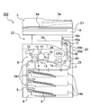
- FIG. 1 is a schematic sectional view showing an internal configuration of an image forming apparatus 100 equipped with a solenoid device 30 of the present invention.
- FIG. 1 is an enlarged view of the periphery of a paper discharge unit in the image forming apparatus 100 of FIG.
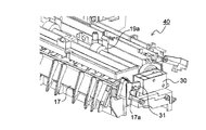
- FIG. 7 is a partial perspective view of the discharge unit 40 including the switching guide 17 and shows a state in which the switching guide 17 is disposed at a position for guiding the paper P to the first discharge roller pair 19a.
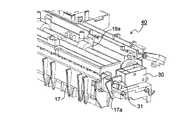
- FIG. 7 is a partial perspective view of the discharge unit 40 including the switching guide 17 and shows a state in which the switching guide 17 is disposed at a position for guiding the paper P to the second discharge roller pair 19b.
- movement of the plunger 31 in the solenoid apparatus 30 which concerns on 2nd Embodiment of this invention. It is sectional drawing of the solenoid apparatus 30 which concerns on 3rd Embodiment of this invention, and is a figure which shows the state which the plunger 31 protruded from the solenoid main body 30a. It is sectional drawing of the solenoid apparatus 30 of 3rd Embodiment, and is a figure which shows the state by which the plunger 31 was drawn in in the solenoid main body 30a.
- the main body housing 20 is provided with various mechanisms to be described later for transferring an image onto a sheet based on an electric signal of the read document image.
- a control unit (CPU) 80 for controlling the operation of each device and each member in the image forming apparatus 100 is disposed.
- the main body housing 20 includes a lower housing 20a and a connecting housing 20b that is positioned along the right side of FIG.
- the lower housing 20a is provided with a paper feeding unit 4 for the paper P, an image forming unit 6 for forming a toner image on the paper P, a fixing unit 7 for fixing the toner image formed on the paper P, and the like. It is done.
- the connection housing 20 b is provided with a paper discharge portion for conveying the fixed paper P and discharging it from the main body housing 20. Further, an in-cylinder discharge space 22 that is largely open toward the left side and the front is formed on the left side of the connecting housing 20b immediately below the upper housing 21.
- the sheet feeding unit 4 disposed in the lower part, the sheet conveying unit 5 disposed on the side and above the sheet feeding unit 4, and the sheet feeding unit 4 are disposed above the sheet feeding unit 4.
- An image forming unit 6 and a fixing unit 7 disposed downstream of the image forming unit 6 in the sheet conveying direction (right side in FIG. 1) are provided.
- the image forming unit 6 and the fixing unit 7 are elongated in the width direction (the direction perpendicular to the paper surface of FIG. 1) perpendicular to the paper transport direction inside the image forming apparatus 100.
- the paper feeding unit 4 is provided with a plurality of paper feeding cassettes 4a provided with separation feeding means such as paper feeding rollers on the downstream side in the paper transport direction.
- a bundle of sheets P placed in the sheet feeding cassette 4a is fed one by one from the uppermost sheet P to the sheet conveying section 5 by the rotation operation of the sheet feeding roller.
- the paper transport unit 5 transports the paper P fed from the paper feed unit 4 to the image forming unit 6 by each transport roller pair 5a.
- the image forming unit 6 forms a predetermined toner image on the paper P by an electrophotographic process.
- the image forming unit 6 includes a photosensitive drum 10 which is an image carrier that is rotatably supported, and a charging device 11, an exposure device 12, and the like arranged around the photosensitive drum 10 along the rotation direction.
- a developing device 13, a transfer device 14, a cleaning device 15, and a static elimination device are provided.
- the fixing unit 7 heats and presses the sheet P on which the toner image has been formed in the image forming unit 6 between a pair of fixing rollers 7a including a heating roller and a pressure roller, thereby forming an unfixed toner image. Fix on the paper P.
- an image reading unit 8 is provided in the upper housing 21.
- the image reading unit 8 reads image information of a document.
- the original conveying device 3 is opened and the original is placed on the contact glass 8 a provided on the upper surface of the upper housing 21.
- the original bundle is automatically read one by one, the original bundle is placed on the paper feed tray 3a of the original conveying device 3 in a closed state.
- the originals from the original bundle are automatically and sequentially sent onto the contact glass 8a one by one.
- the document located on the contact glass 8a is irradiated with light from an exposure lamp (not shown), and the reflected light is photoelectrically converted as image light through an optical system such as a reflection mirror (not shown) and an imaging lens. Part (CCD).
- an optical system such as a reflection mirror (not shown) and an imaging lens. Part (CCD).
- the surface of the photosensitive drum 10 that rotates counterclockwise in FIG. 1 is uniformly charged by the charging device 11. Then, based on the image information read by the image reading unit 8, a laser beam from the exposure device 12 (laser scanning unit or the like) is irradiated on the peripheral surface of the photoconductive drum 10, thereby causing the surface of the photoconductive drum 10 to be irradiated. An electrostatic latent image is formed. By supplying toner as a developer from the developing device 13 to the electrostatic latent image, a toner image is formed.
- the paper P is sent from the paper supply unit 4 to the paper transport path 5 and temporarily stops at the registration roller pair 9.
- the paper P stopped by the registration roller pair 9 is conveyed toward the photosensitive drum 10 on which the toner image is formed at a predetermined timing.
- the toner image on the surface of the photosensitive drum 10 is transferred onto the paper P by the transfer device 14 including a transfer roller or the like.
- the sheet P on which the toner image has been transferred is separated from the photosensitive drum 10, conveyed to the fixing unit 7, and heated and pressurized by passing through the fixing roller pair 7a to fix the toner image.
- the cleaning device 15 After the transfer of the toner image onto the paper P is completed, the residual toner remaining on the outer peripheral surface of the photosensitive drum 10 is removed by the cleaning device 15. Further, a charge removal process for removing residual charges on the surface of the photosensitive drum 10 is performed by a charge removal device (not shown). Thereafter, the peripheral surface is charged again by the charging device 11, and image formation is performed in the same manner.
- the sheet P that has passed through the fixing unit 7 is conveyed into the connecting housing 20b along the vertical conveyance path 18 that extends vertically upward.
- the upper part of the vertical conveyance path 18 is branched into two upper and lower conveyance paths toward the left in the connecting housing 20b, and the conveyance direction of the paper P is switched by the switching guide 17 arranged at the branching portion.
- a paper discharge unit including a first discharge roller pair 19a and a second discharge roller pair 19b disposed immediately above the first discharge roller pair 19a is provided.
- the sheet P conveyed on the vertical conveyance path 18 is guided to the upper conveyance path or the lower conveyance path by the switching guide 17.
- the paper P guided to the lower conveyance path by the switching guide 17 is discharged to the left from the first discharge roller pair 19 a and is stocked on the first paper discharge tray 24 formed on the bottom surface of the in-cylinder discharge space 22.
- the paper P guided to the upper conveyance path by the switching guide 17 is discharged leftward from the second discharge roller pair 19 b and is discharged onto the second paper discharge tray 25.
- the switching guide 17 is configured to switch the guide direction of the paper P by a control signal from the control unit 80.
- a paper pressing member 27 is swingably provided near the downstream side of the first discharge roller pair 19a and the second discharge roller pair 19b with respect to the paper discharge direction. The sheet pressing member 27 presses the rear end of the sheet P discharged from the first discharge roller pair 19a and the second discharge roller pair 19b from above.
- the paper P that has passed through the fixing unit 7 is guided to the upper conveyance path by the switching guide 17. Then, a part of the paper P is once protruded from the second discharge roller pair 19b to the outside of the apparatus. Thereafter, the paper P is switched to the reverse conveyance path 23 by switching the second discharge roller pair 19b in the reverse direction (switchback) and distributed to the reverse conveyance path 23. Re-conveyed. Then, the next image formed on the photosensitive drum 10 is transferred to the surface of the paper P on which the image is not formed by the transfer device 14. Thereafter, the sheet P is conveyed to the fixing unit 7 and the toner image is fixed, and then discharged to the first sheet discharge tray 24 through the first discharge roller pair 19a.
- FIG. 3 and 4 are partial perspective views of the discharge unit 40 provided with the switching guide 17.
- FIG. 3 shows a state in which the switching guide 17 is arranged at a position for guiding the paper P to the first discharge roller pair 19a
- FIG. 4 shows a state in which the switching guide 17 is arranged at a position for guiding the paper P to the second discharge roller pair 19b.
- Is shown. 3 and 4 show a state in which the discharge unit 40 is viewed from the back side of the image forming apparatus 100 (the back side of the paper surface in FIG. 1).
- the discharge unit 40 includes a first discharge roller 19a, a switching guide 17, and a solenoid device 30.
- the switching guide 17 is swingably supported by the housing of the discharge unit 40, and an arm portion 17a is formed at one end of the swing shaft.
- a plunger 31 of a solenoid device 30 is connected to the arm portion 17a.
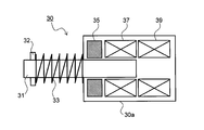
- FIG. 5 is a cross-sectional view of the solenoid device 30 according to the first embodiment of the present invention, in which the arrangement of the switching guide 17 is changed.
- the solenoid device 30 has an iron plunger 31 that can project or retract with respect to the solenoid body 30a.
- a locking portion 32 is formed at the tip of the plunger 31, and a coil spring 33 is inserted between the solenoid body 30 a and the locking portion 32.
- an attracting permanent magnet 35, a return coil (second coil) 37, and a suction coil (first coil) 39 are arranged in this order from the side close to the protruding direction of the plunger 31.
- the attracting permanent magnet 35, the return coil 37, and the attracting coil 39 are cylindrical, and are arranged so as to surround the outer peripheral surface of the plunger 31 in a state where the plunger 31 is drawn into the solenoid body 30a.
- the winding directions of the coil wires are opposite to each other.
- FIG. 5 shows a state where the plunger 31 protrudes from the solenoid body 30a (returned state).
- the solenoid device 30 When discharging the paper P to the first paper discharge tray 24, the solenoid device 30 is set to the suction state shown in FIG. As a result, as shown in FIG. 3, the plunger 31 drawn into the solenoid body 30a swings the arm portion 17a in the clockwise direction, so that the switching guide 17 also swings in the clockwise direction (horizontal direction). . As a result, the switching guide 17 is disposed at a position (hereinafter referred to as a first position) for guiding the paper P to the first discharge roller pair 19a along the back surface side (the lower surface side in FIG. 3) of the switching guide 17.
- a first position for guiding the paper P to the first discharge roller pair 19a along the back surface side (the lower surface side in FIG. 3) of the switching guide 17.
- the solenoid device 30 When discharging the paper P to the second paper discharge tray 25, the solenoid device 30 is set in the return state shown in FIG. As a result, as shown in FIG. 4, the plunger 31 protruding from the solenoid body 30a swings the arm portion 17a in the counterclockwise direction, so that the switching guide 17 also swings in the counterclockwise direction (vertical direction). . As a result, the switching guide 17 is disposed at a position (hereinafter referred to as a second position) for guiding the paper P to the second discharge roller pair 19b along the front surface side (left surface side in FIG. 4) of the switching guide 17.
- a second position for guiding the paper P to the second discharge roller pair 19b along the front surface side (left surface side in FIG. 4) of the switching guide 17.
- FIG. 7 is a graph showing a change in applied voltage applied to the suction coil 39 during the suction operation of the plunger 31 in the solenoid device 30 of the first embodiment.
- the reference voltage V1 is applied at the start T1 of the suction operation, and the plunger 31 starts to be pulled with a strong force.
- a voltage V2 lower than the reference voltage V1 is applied until the suction operation is scheduled to be completed T2.
- the plunger 31 is inserted deeply into the suction coil 39, so that a sufficient suction force is generated even at a low voltage.
- the reference voltage V1 is applied at the start of the return operation T1 in the same manner as in FIG. 7, and the pushing out of the plunger 31 is started with a strong force.
- a voltage V2 lower than the reference voltage V1 is applied until a scheduled completion time T2 set by predicting completion of the return operation.
- the inertial force acting on the plunger 31 is reduced and the restoring force of the coil spring 33 also acts, so that a sufficient pushing force is generated even at a low voltage.
- the voltage V1 is applied again for a short time (for error avoidance) to reliably move the plunger 31 to the return state, and the voltage is applied to the return coil 37.
- the pulling force of the plunger 31 immediately before the completion of the suction operation and the pushing force of the plunger 31 immediately before the completion of the return operation are optimized, and the moving speed of the plunger 31 is reduced. Therefore, the impact when the plunger 31 is drawn into the solenoid body 30a and when the plunger 31 protrudes from the solenoid body 30a is alleviated. Therefore, it is possible to effectively suppress the occurrence of collision noise and vibration between the plunger 31 and the solenoid body 30a, and the switching guide 17 can be smoothly switched between the first position and the second position.
- the timing of switching from the reference voltage V1 to the voltage V2 depends on conditions such as the spring constant of the coil spring 33, the strength of the magnetic force of the permanent magnet 35 for adsorption, or the number of turns of the return coil 37 and the suction coil 39. It can be set as appropriate between the start of the operation (or return operation) and the completion of the suction operation (or return operation).
- the magnitude of the voltage V2 can also be set as appropriate according to the above-described conditions.
- Switching of the voltage applied to the suction coil 39 and the return coil 37 is controlled by the control unit 80 (see FIG. 1).
- PWM Pulse
- Width Modulation Width Modulation
- FIG. 8 is a graph showing changes in the applied voltage applied to the return coil 37 during the suction operation of the plunger 31 in the solenoid device 30 according to the second embodiment of the present invention.
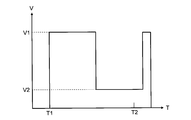
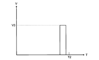
- the solenoid device 30 of this embodiment has the same configuration as the solenoid device 30 of the first embodiment shown in FIGS. 5 and 6. Then, the voltages V1 and V2 shown in FIG. 7 are applied to the suction coil 39 during the suction operation, and as shown in FIG. 8, after a predetermined time has elapsed from the start T1 of the suction operation (the applied voltage is changed from V1 in FIG. 7). After switching to V2), a buffer voltage V3 lower than the reference voltage V1 is applied to the return coil 37 for a short time until the suction operation is scheduled to be completed T2.
- the voltages V1 and V2 shown in FIG. 7 are applied to the return coil 37, and as shown in FIG. 8, after a predetermined time has elapsed from the start T1 of the return operation (see FIG. 7), the buffer voltage V3 lower than the reference voltage V1 is applied to the suction coil 39 for a short time until the return operation is scheduled to be completed T2.
- the PWM method is used as in the first embodiment.
- the switching timing from the reference voltage V1 to the voltage V2, the application timing of the buffer voltage V3, the voltage V2, and the magnitude of the buffer voltage V3 are the same as in the first embodiment. It can be set as appropriate according to the strength of the magnetic force or the number of turns of the return coil 37 and the suction coil 39.
- FIG. 9 and 10 are sectional views of the solenoid device 30 according to the third embodiment of the present invention.
- FIG. 9 shows a state in which the plunger 31 is drawn into the solenoid body 30a.
- FIG. 10 shows a state in which the plunger 31 protrudes from the solenoid body 30a.
- the solenoid device 30 according to the present embodiment does not include the permanent magnet 35 and the return coil 37, and the plunger 31 is applied by continuously applying a voltage to the suction coil 39 even after the suction operation is completed. Hold in suction position. Further, during the return operation, the plunger 31 is moved to the return position by the restoring force of the coil spring 33 by cutting off the voltage application to the suction coil 39.
- FIG. 11 is a graph showing changes in the applied voltage applied to the suction coil 39 during the suction operation of the plunger 31 in the solenoid device 30 of the third embodiment.
- the reference voltage V1 is applied at the time T1 when the suction operation starts, and the pull-in of the plunger 31 is started with a strong force.
- a voltage V2 lower than the reference voltage V1 is applied until the suction operation is scheduled to be completed T2.
- the plunger 31 is inserted deeply into the suction coil 39, so that a sufficient suction force is generated even at a low voltage.
- the voltage V1 is continuously applied again in order to hold the plunger 31 in the attracted state.
- the pulling force of the plunger 31 immediately before the completion of the suction operation is optimized, and the moving speed of the plunger 31 is reduced. Therefore, the plunger 31 is pulled into the solenoid body 30a. The impact is reduced. Therefore, it is possible to effectively suppress the occurrence of collision noise and vibration between the plunger 31 and the solenoid body 30a, and to smoothly switch the switching guide 17 from the second position to the first position.
- the present invention is not limited to the above embodiments, and various modifications can be made without departing from the spirit of the present invention.
- the switching guide 17 is moved using the solenoid device 30, but the member that is moved by the solenoid device 30 is not limited to the switching guide 17, and other members in the image forming apparatus 100. There may be.
- the voltage V1 is again applied to the adsorption coil 39 or the return coil 37 for a short time after the time T2 when the suction operation or the return operation is scheduled to be completed. It is not always necessary, and it is possible to end the application while switching to the voltage V2.
- the present invention is not limited to the monochrome multifunction device shown in FIG. 1, but is also applicable to other image forming apparatuses such as color copying machines, monochrome and color printers, facsimiles, or other electronic devices using solenoid devices. Of course you can.
- the present invention can be used for a push-pull type solenoid device that moves a plunger between an adsorption position and a return position.
- a solenoid device that can suppress a plunger and a collision sound of a member movable by the plunger with a simple configuration, and an image forming apparatus including the solenoid device.
Landscapes
- Physics & Mathematics (AREA)
- Electromagnetism (AREA)
- Engineering & Computer Science (AREA)
- Power Engineering (AREA)
- Mechanical Engineering (AREA)
- Plasma & Fusion (AREA)
- General Physics & Mathematics (AREA)
- Electrophotography Configuration And Component (AREA)
Abstract
ソレノイド装置(30)は、ソレノイド本体(30a)と、プランジャー(31)と、第1コイル(39)と、付勢部材(33)と、を備える。プランジャー(31)は、ソレノイド本体(30a)内に引き込まれた吸着位置と、ソレノイド本体(30a)から突出した復帰位置とに選択配置される。第1コイル(39)は、ソレノイド本体(30a)内に配置され、基準電圧の印加によりプランジャー(31)を復帰位置から吸着位置に移動させる力を発生させる。付勢部材(33)は、プランジャー(31)を復帰位置方向に付勢する。プランジャー(31)を復帰位置から吸着位置へ移動させる吸着動作の開始後、吸着動作の完了時までの間に、第1コイル(39)に印加する電圧が基準電圧から基準電圧よりも低い所定電圧に切り替えられる。
Description
本発明は、ソレノイド装置及びそれを備えた複写機、プリンター、ファクシミリ等の画像形成装置に関する。
従来、画像形成装置等の電子機器の可動部材の駆動源として、ソレノイド装置が広く用いられている。ソレノイド装置は、通常時はスプリングによりコイルから離間した位置にプランジャー(可動鉄心)があり、コイルを励磁するとプランジャーがコイル側に移動する。
上記のようなソレノイド装置においては、プランジャーが作動する際の衝突音や振動が問題となる。そこで、プランジャーの作動時に発生する衝突音や振動を抑制する方法が種々提案されており、例えば特許文献1には、フラッパー(可動片)とフラッパーを支持する支持部との間に吸音静音材を介在させた電磁ソレノイドが開示されている。
しかし、特許文献1の構成では、フラッパーの接触部に吸音静音材を挿入する構成であるため、部材点数や組み立て工数が多くなるとともに、コストも高くなるという問題点があった。また、可動片自体の作動は変化しないため、画像形成装置の切り替えガイド等のような、可動片により可動する部材の衝突音を低減することはできなかった。
本発明は、上記問題点に鑑み、プランジャーにより可動する部材の衝突音を簡単な構成で抑制できるソレノイド装置、及びそれを備えた画像形成装置を提供することを目的とする。
上記目的を達成するために本発明の構成は、ソレノイド本体と、プランジャーと、第1コイルと、付勢部材と、を備えたソレノイド装置である。プランジャーは、ソレノイド本体内に引き込まれた吸着位置と、ソレノイド本体から突出した復帰位置とに選択配置される。第1コイルは、ソレノイド本体内に配置され、基準電圧の印加によりプランジャーを復帰位置から吸着位置に移動させる力を発生させる。付勢部材は、プランジャーを復帰位置方向に付勢する。プランジャーを復帰位置から吸着位置へ移動させる吸着動作の開始後、吸着動作の完了時までの間に、第1コイルに印加する電圧が基準電圧から基準電圧よりも低い所定電圧に切り替えられる。
本発明の構成によれば、吸引動作の完了直前におけるプランジャーの引き込み力が適正化され、プランジャーの移動速度が低減されるため、プランジャーがソレノイド本体内に引き込まれたときの衝撃が緩和される。従って、プランジャーとソレノイド本体との衝突音や振動の発生を効果的に抑制することができる。
以下、図面を参照しながら本発明の実施形態について詳細に説明する。図1は、本発明のソレノイド装置30が搭載された画像形成装置100の内部構成を示す概略図であり、図2は、図1の画像形成装置100における用紙排出部周辺の拡大図である。図1に示すように、画像形成装置100は、いわゆる胴内排紙型のデジタル複合機であって、大まかには、本体ハウジング20と、その上部に配設された上ハウジング21とで構成されている。上ハウジング21には、原稿の画像を電気信号として読み取るための後述する各種機構が設けられ、上ハウジング21の上部には原稿搬送装置3が付設されている。他方、本体ハウジング20には、読み取った原稿画像の電気信号に基づいて用紙に画像を転写するための後述する各種機構が設けられている。更に、画像形成装置100内には、画像形成装置100内の各装置、各部材の動作を制御する制御部(CPU)80が配置されている。
本実施形態では、本体ハウジング20は、下ハウジング20aと、その上方で図1の右側部に沿って位置し、上ハウジング21に連結される連結ハウジング20bと、から構成される。下ハウジング20aには、用紙Pの給紙部4や、用紙P上にトナー画像を形成する画像形成部6や、用紙P上に形成されたトナー画像を定着するための定着部7等が設けられる。他方、連結ハウジング20bには、定着後の用紙Pを搬送して本体ハウジング20から排出するための用紙排出部が設けられている。また、上ハウジング21の直下における連結ハウジング20bの左側方には、左側面及び正面に向けて大きく開放された胴内排出空間22が形成されている。
本体ハウジング20内には、下部に配設された給紙部4と、給紙部4の側方及び上方に配設された用紙搬送部5と、給紙部4の上方に配設された画像形成部6と、画像形成部6の用紙搬送方向下流側(図1の右側)に配設された定着部7とが備えられている。画像形成部6及び定着部7は、画像形成装置100の内部で用紙搬送方向と直交する幅方向(図1の紙面と垂直な方向)に細長く配設されている。
給紙部4には、用紙搬送方向下流側に給紙ローラー等の分離給送手段が設けられた複数の給紙カセット4aが備えられている。この給紙カセット4aに載置された用紙Pの束を、給紙ローラーの回転動作によって、最上位の用紙Pから1枚ずつ用紙搬送部5に給紙する。用紙搬送部5は、給紙部4から給紙された用紙Pを、各搬送ローラー対5aによって画像形成部6へと搬送する。
画像形成部6は、電子写真プロセスによって、用紙P上に所定のトナー像を形成する。画像形成部6は、回転可能に軸支された像担持体である感光体ドラム10と、この感光体ドラム10の周囲にその回転方向に沿って配設される帯電装置11、露光装置12、現像装置13、転写装置14、クリーニング装置15、及び不図示の除電装置を備えている。定着部7は、画像形成部6においてトナー像が形成された用紙Pを、加熱ローラーと加圧ローラーとからなる一対の定着ローラー対7aに挟持させて加熱及び加圧して、未定着トナー像を用紙P上に定着させる。
上ハウジング21内には、画像読取部8が設けられている。画像読取部8は、原稿の画像情報を読み取るものである。原稿を1枚ずつ手置きで読み取らせる場合には、原稿搬送装置3を開いて上ハウジング21の上面に設けられたコンタクトガラス8a上に原稿を載置する。また、原稿束を1枚ずつ自動的に読み取らせる場合には、原稿束を、閉じた状態の原稿搬送装置3の給紙トレイ3a上に載置する。原稿束が給紙トレイ3a上に載置された場合は、当該原稿束から原稿が1枚ずつ自動的に順次コンタクトガラス8a上に送り込まれるようになっている。いずれの場合でもコンタクトガラス8a上に位置した原稿に、不図示の露光ランプから光が照射され、その反射光は画像光として不図示の反射鏡及び結像レンズ等の光学系を介して光電変換部(CCD)へ導かれる。
以下、上記のように構成された画像形成装置100の基本的な動作を説明する。先ず、図1の反時計回り方向に回転する感光体ドラム10の表面が帯電装置11によって一様に帯電される。そして、引き続き画像読取部8で読み取られた画像情報に基づいて露光装置12(レーザー走査ユニット等)からのレーザービームが感光体ドラム10の周面に照射され、これによって感光体ドラム10の表面に静電潜像が形成される。この静電潜像に現像装置13から現像剤としてのトナーが供給されることによりトナー像が形成される。
トナー像の形成と並行して、用紙Pが給紙部4から用紙搬送路5に送出され、レジストローラー対9で一旦停止する。そして、レジストローラー対9で停止した用紙Pは所定のタイミングでトナー像が形成された感光体ドラム10に向けて搬送される。そして、転写ローラー等からなる転写装置14により感光体ドラム10の表面のトナー像が用紙Pに転写される。トナー像が転写された用紙Pは感光体ドラム10から分離され、定着部7に向けて搬送され、定着ローラー対7aを通過することで加熱、加圧処理されてトナー像が定着される。
用紙Pへのトナー像の転写処理が完了した感光体ドラム10は、クリーニング装置15により感光体ドラム10の外周面に残留している残留トナーが取り除かれる。さらに、除電装置(不図示)により感光体ドラム10の表面の残留電荷を除去する除電処理が施される。その後、帯電装置11により再び周面に帯電処理が施され、以下同様にして画像形成が行われることとなる。
そして、定着部7を通過した用紙Pは、そのまま垂直上方に向かう垂直搬送路18に沿って連結ハウジング20b内に搬送される。垂直搬送路18の上部は連結ハウジング20b内で左方に向かって上下2つの搬送路に分岐しており、分岐部に配置された切り替えガイド17によって、用紙Pの搬送方向が切り替えられる。
この連結ハウジング20b内には、第1排出ローラー対19aと、第1排出ローラー対19aの直上に配置された第2排出ローラー対19bと、で構成される用紙排出部が設けられている。垂直搬送路18を搬送された用紙Pは、切り替えガイド17によって上方の搬送路若しくは下方の搬送路に案内される。
切り替えガイド17によって下方の搬送路に案内された用紙Pは、第1排出ローラー対19aから左方に排出され、胴内排出空間22の底面に形成された第1用紙排出トレイ24上にストックされる。一方、切り替えガイド17によって上方の搬送路に案内された用紙Pは、第2排出ローラー対19bから左方に排出され、第2用紙排出トレイ25上に排出される。切り替えガイド17は、制御部80からの制御信号によって用紙Pの案内方向を切り替えるようになっている。また、用紙排出方向に対し第1排出ローラー対19a及び第2排出ローラー対19bの下流側直近には、用紙押さえ部材27が揺動可能に設けられている。用紙押さえ部材27は、第1排出ローラー対19a及び第2排出ローラー対19bから排出される用紙Pの後端を上方から押圧する。
一方、用紙Pの両面に印字を行う場合は、定着部7を通過した用紙Pを切り替えガイド17によって上方の搬送路に案内する。そして、用紙Pの一部を一旦第2排出ローラー対19bから装置外部にまで突出させる。その後、用紙Pは第2排出ローラー対19bを逆回転させることにより搬送方向の切り替え(スイッチバック)が行われて反転搬送路23に振り分けられ、画像面を反転させた状態でレジストローラー対9に再搬送される。そして、感光体ドラム10上に形成された次の画像が転写装置14により用紙Pの画像が形成されていない面に転写される。その後、用紙Pは定着部7に搬送されてトナー像が定着された後、第1排出ローラー対19aを介して第1用紙排出トレイ24に排出される。
第2排出ローラー対19bを用いて両面印字を行う用紙Pをスイッチバックさせる上記の構成とすることで、用紙Pのスイッチバック動作中に後続の用紙Pを第1排出ローラー対19aから第1用紙排出トレイ24上に排出することができる。従って、両面印字を行う用紙のスイッチバック動作の終了を待たずに後続の用紙Pの画像形成処理及び排出を行うことができ、画像形成効率が向上する。
なお、ユーザーが操作パネル(図示せず)上で用紙Pの案内方向を切り替えることもできる。例えば、通常の画像形成処理を行った用紙Pは第1排出ローラー対19aから第1用紙排出トレイ24に排出し、ファクシミリの受信データ等を印字する場合には、用紙Pを第2排出ローラー対19bから第2用紙排出トレイ25上に排出することができる。
図3及び図4は、切り替えガイド17を備えた排出ユニット40の部分斜視図である。図3は、切り替えガイド17が用紙Pを第1排出ローラー対19aに案内する位置に配置された状態を示しており、図4は、第2排出ローラー対19bに案内する位置に配置された状態を示している。なお、図3及び図4は、排出ユニット40を画像形成装置100の背面側(図1の紙面奥側)から見た状態を示している。
排出ユニット40は、第1排出ローラー19aと、切り替えガイド17と、ソレノイド装置30とを備える。切り替えガイド17は、排出ユニット40の筐体に揺動可能に支持されており、揺動軸の一端部にアーム部17aが形成されている。アーム部17aにはソレノイド装置30のプランジャー31が連結されている。
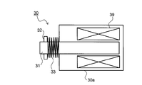
図5は、切り替えガイド17の配置を変更する、本発明の第1実施形態に係るソレノイド装置30の断面図である。ソレノイド装置30は、ソレノイド本体30aに対して突出または引き込み可能な鉄製のプランジャー31を有している。プランジャー31の先端には係止部32が形成されており、ソレノイド本体30aと係止部32との間にはコイルバネ33が外挿されている。
ソレノイド本体30a内には、プランジャー31の突出方向に近い側から順に吸着用永久磁石35、復帰用コイル(第2コイル)37、吸引用コイル(第1コイル)39が配置されている。吸着用永久磁石35、復帰用コイル37、吸引用コイル39は円筒状であり、プランジャー31がソレノイド本体30aに引き込まれた状態で、プランジャー31の外周面を囲むように配置されている。復帰用コイル37、吸引用コイル39はコイル線の巻き方向が互いに逆方向となっている。
次に、本実施形態のソレノイド装置30の作動について説明する。図5はプランジャー31がソレノイド本体30aから突出した状態(復帰状態)を示している。図5の状態から吸引用コイル39に電圧を印加すると、吸引用コイル39から発生する磁力線によってプランジャー31が励磁され、プランジャー31がソレノイド本体30a内に移動する方向(図5の左から右方向)の力が発生する。これにより、プランジャー31がコイルバネ33の付勢力に抗して吸着用永久磁石35に吸着され、図6に示すようにプランジャー31がソレノイド本体30a内に引き込まれた状態(吸着状態)となる。この状態で吸引用コイル39への電圧の印加を遮断しても、プランジャー31は吸着用永久磁石35により吸着状態が保持される。
第1用紙排出トレイ24に用紙Pを排出する場合は、ソレノイド装置30を図6に示す吸着状態とする。これにより、図3に示すように、ソレノイド本体30a内に引き込まれたプランジャー31がアーム部17aを時計回り方向に揺動させるため、切り替えガイド17も時計回り方向(水平方向)に揺動する。その結果、切り替えガイド17は用紙Pを切り替えガイド17の裏面側(図3の下面側)に沿って第1排出ローラー対19aに案内する位置(以下、第1の位置という)に配置される。
図6の状態から復帰用コイル37に電圧を印加すると、復帰用コイル37から発生する磁力線によってプランジャー31が励磁され、プランジャー31がソレノイド本体30aの外側に移動する方向(図5の右から左方向)の力が発生する。これにより、プランジャー31が吸着用永久磁石35の磁力に抗してソレノイド本体30aから突出し、図5に示した復帰状態に戻る。この状態で復帰用コイル37への電圧の印加を遮断しても、プランジャー31はコイルバネ33により復帰状態が保持される。
第2用紙排出トレイ25に用紙Pを排出する場合は、ソレノイド装置30を図5に示す復帰状態とする。これにより、図4に示すように、ソレノイド本体30aから突出したプランジャー31がアーム部17aを反時計回り方向に揺動させるため、切り替えガイド17も反時計回り方向(垂直方向)に揺動する。その結果、切り替えガイド17は用紙Pを切り替えガイド17の表面側(図4の左面側)に沿って第2排出ローラー対19bに案内する位置(以下、第2の位置という)に配置される。
次に、第1実施形態のソレノイド装置30を用いた切り替えガイド17の切り替え動作時における電圧印加手順について詳細に説明する。従来、プランジャー31を復帰状態から吸着状態に切り替える場合、図12に示すように、吸着動作開始時T1から吸引用コイル39に一定の基準電圧V1を印加し、吸着動作の完了を予測して設定された完了予定時T2の経過後に電圧の印加を遮断していた。
ここで、図5に示すように、プランジャー31の吸引開始直後はプランジャー31と吸引用コイル39との距離が遠い。即ち、吸引用コイル39へのプランジャー31の挿入が浅い。そのため、吸引用コイル39に高い基準電圧V1を印加してプランジャー31を強い力で吸引する必要がある。
一方、吸引動作の後半ではプランジャー31が吸引用コイル39に深く挿入されている。そのため、吸引用コイル39に基準電圧V1を印加し続けるとプランジャー31の吸引力が過剰となり、切り替えガイド17の配置を第2の位置から第1の位置に切り替える際の衝撃が大きくなる。
なお、吸引動作の進行に伴いコイルバネ33が圧縮されていくため、圧縮に比例してコイルバネ33からプランジャー31に作用する反力も大きくなる。しかし、吸引用コイル39へのプランジャー31の挿入も深くなるため、プランジャー31の吸引力が急激に大きくなる。その結果、切り替えガイド17の配置を第2の位置から第1の位置に切り替える際の衝撃もさらに大きくなる。
同様に、プランジャー31を吸着状態から復帰状態に切り替える場合も、復帰動作の開始直後は吸着用永久磁石35の磁力よりも大きい力をプランジャー31に作用させるために復帰用コイル37に高い基準電圧V1を印加する必要がある。一方、復帰動作の後半ではプランジャー31が静止状態から動き出しているため、プランジャー31に作用する慣性力が静止状態に比べて小さくなるとともに、圧縮されていたコイルバネ33の付勢力(復元力)がプランジャー31に作用する。そのため、復帰用コイル37に基準電圧V1を印加し続けるとプランジャー31の吸引力が過剰となり、切り替えガイド17の配置を第1の位置から第2の位置に切り替える際の衝撃も大きくなる。
そこで、本発明では、プランジャー31の切り替え動作の後半に復帰用コイル37または吸引用コイル39に印加する電圧を低下させることにより、切り替え動作後半のプランジャー31の速度を小さくして動作完了時の衝撃を低減することとした。
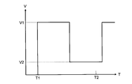
図7は、第1実施形態のソレノイド装置30における、プランジャー31の吸引動作時に吸引用コイル39に印加する印加電圧の変化を示すグラフである。図7に示すように、吸着動作開始時T1には基準電圧V1を印加して、強い力でプランジャー31の引き込みを開始する。そして、T1から所定時間が経過すると、基準電圧V1よりも低い電圧V2を吸引動作の完了予定時T2まで印加する。吸着動作の後半ではプランジャー31は吸引用コイル39内に深く挿入されるため、低い電圧でも十分な吸引力が発生する。その後、吸引動作の完了予定時T2の経過後に、プランジャー31を吸着状態まで確実に移動させるために(エラー回避用に)再び電圧V1を短時間印加し、吸引用コイル39への電圧の印加を終了する。
また、プランジャー31の復帰動作時においても、図7と同様に復帰動作開始時T1には基準電圧V1を印加して、強い力でプランジャー31の押し出しを開始する。そして、T1から所定時間が経過すると、基準電圧V1よりも低い電圧V2を復帰動作の完了を予測して設定された完了予定時T2まで印加する。復帰動作の後半ではプランジャー31に作用する慣性力が小さくなるとともに、コイルバネ33の復元力も作用するため、低い電圧でも十分な押し出し力が発生する。その後、復帰動作の完了予定時T2の経過後に、プランジャー31を復帰状態まで確実に移動させるために(エラー回避用に)再び電圧V1を短時間印加し、復帰用コイル37への電圧の印加を終了する。
上記の手順で電圧を印加することにより、吸引動作の完了直前におけるプランジャー31の引き込み力、及び復帰動作の完了直前におけるプランジャー31の押し出し力が適正化され、プランジャー31の移動速度が低減されるため、プランジャー31がソレノイド本体30a内に引き込まれたとき、及びソレノイド本体30aから突出したときの衝撃が緩和される。従って、プランジャー31とソレノイド本体30aとの衝突音や振動の発生を効果的に抑制することができ、切り替えガイド17を第1の位置と第2の位置とに円滑に切り替えることができる。
基準電圧V1から電圧V2への切り替えタイミングは、コイルバネ33のバネ定数や吸着用永久磁石35の磁力の強さ、或いは復帰用コイル37、吸引用コイル39の巻き数等の条件に応じて、吸着動作(または復帰動作)の開始後、吸着動作(または復帰動作)の完了までの間で適宜設定することができる。また、電圧V2の大きさについても、上述した条件に応じて適宜設定することができる。
吸引用コイル39、復帰用コイル37へ印加する電圧の切り替えは制御部80(図1参照)によって制御される。電圧の切り替え方式としては、周波数は変化させずに入力信号(DCレベル)の大きさに応じて、パルス幅のデュ-ティ・サイクル(パルス幅のHとLの比)を変化させるPWM(Pulse Width Modulation)方式を用いることができる。
図8は、本発明の第2実施形態に係るソレノイド装置30における、プランジャー31の吸引動作時に復帰用コイル37に印加する印加電圧の変化を示すグラフである。本実施形態のソレノイド装置30は、図5及び図6に示した第1実施形態のソレノイド装置30と同様の構成である。そして、吸引動作時に吸引用コイル39に図7に示した電圧V1、V2を印加するとともに、図8に示すように、吸引動作開始時T1から所定時間経過後(図7で印加電圧がV1からV2に切り替えられた後)、吸引動作の完了予定時T2までの間に、復帰用コイル37に基準電圧V1よりも低い緩衝電圧V3を短時間印加する。
また、プランジャー31の復帰動作時においても、復帰用コイル37に図7に示した電圧V1、V2を印加するとともに、図8に示すように、復帰動作開始時T1から所定時間経過後(図7で印加電圧がV1からV2に切り替えられた後)、復帰動作の完了予定時T2までの間に、吸引用コイル39に基準電圧V1よりも低い緩衝電圧V3を短時間印加する。電圧の切り替え方法は、第1実施形態と同様にPWM方式が用いられる。
上記の手順で電圧を印加することにより、吸着動作または復帰動作の後半に緩衝電圧V3によってプランジャー31に逆向きの力が作用するため、プランジャー31の速度をより小さくすることができる。従って、第1実施形態に比べてプランジャー31とソレノイド本体30aとの衝突音や振動の発生をより一層効果的に抑制することができる。基準電圧V1から電圧V2への切り替えタイミング、緩衝電圧V3の印加タイミング、電圧V2、緩衝電圧V3の大きさについても、第1実施形態と同様に、コイルバネ33のバネ定数や吸着用永久磁石35の磁力の強さ、或いは復帰用コイル37、吸引用コイル39の巻き数等に応じて適宜設定することができる。
図9及び図10は、本発明の第3実施形態に係るソレノイド装置30の断面図である。図9は、プランジャー31がソレノイド本体30aに引き込まれた状態を示している。図10は、プランジャー31がソレノイド本体30aから突出した状態を示している。本実施形態のソレノイド装置30は、吸着用永久磁石35及び復帰用コイル37を有しておらず、吸着動作の完了後も吸引用コイル39に継続して電圧を印加することでプランジャー31を吸着位置に保持する。また、復帰動作時には吸着用コイル39への電圧の印加を遮断することで、コイルバネ33の復元力によりプランジャー31が復帰位置に移動する。
図11は、第3実施形態のソレノイド装置30における、プランジャー31の吸引動作時に吸引用コイル39に印加する印加電圧の変化を示すグラフである。図11に示すように、吸着動作開始時T1には基準電圧V1を印加して、強い力でプランジャー31の引き込みを開始する。そして、T1から所定時間が経過すると、基準電圧V1よりも低い電圧V2を吸引動作の完了予定時T2まで印加する。吸着動作の後半ではプランジャー31は吸引用コイル39内に深く挿入されるため、低い電圧でも十分な吸引力が発生する。その後、吸引動作の完了予定時T2の経過後に、プランジャー31を吸着状態で保持するために再び電圧V1を継続して印加する。
上記の手順で電圧を印加することにより、吸引動作の完了直前におけるプランジャー31の引き込み力が適正化され、プランジャー31の移動速度が低減されるため、プランジャー31がソレノイド本体30a内に引き込まれたときの衝撃が緩和される。従って、プランジャー31とソレノイド本体30aとの衝突音や振動の発生を効果的に抑制することができ、切り替えガイド17を第2の位置から第1の位置に円滑に切り替えることができる。
その他、本発明は上記各実施形態に限定されず、本発明の趣旨を逸脱しない範囲で種々の変更が可能である。例えば、上記各実施形態においては、ソレノイド装置30を用いて切り替えガイド17を可動させているが、ソレノイド装置30により可動させる部材は切り替えガイド17に限らず、画像形成装置100内の他の部材であっても良い。
また、上記第1及び第2実施形態では、吸引動作または復帰動作の完了予定時T2の経過後に、吸着用コイル39または復帰用コイル37に再び電圧V1を短時間印加しているが、これは必ずしも必要ではなく、電圧V2へ切り替えた状態で印加を終了することも可能である。
また、本発明は図1に示したようなモノクロ複合機に限らず、カラー複写機、モノクロ及びカラープリンター、ファクシミリ等の、他の画像形成装置、或いはソレノイド装置を用いる他の電子機器にも適用できるのはもちろんである。
本発明は、プランジャーを吸着位置と復帰位置とに移動させるプッシュプル方式のソレノイド装置に利用可能である。本発明の利用により、プランジャー及びプランジャーにより可動する部材の衝突音を簡単な構成で抑制できるソレノイド装置、及びそれを備えた画像形成装置を提供することができる。
Claims (8)
- ソレノイド本体と、
該ソレノイド本体内に引き込まれた吸着位置と、前記ソレノイド本体から突出した復帰位置とに選択配置されるプランジャーと、
前記ソレノイド本体内に配置され、基準電圧の印加により前記プランジャーを前記復帰位置から前記吸着位置に移動させる力を発生させる第1コイルと、
前記プランジャーを前記復帰位置方向に付勢する付勢部材と、
を備え、
前記プランジャーを前記復帰位置から前記吸着位置へ移動させる吸着動作の開始後、前記吸着動作の完了時までの間に、前記第1コイルに印加する電圧が前記基準電圧から前記基準電圧よりも低い所定電圧に切り替えられることを特徴とするソレノイド装置。 - 前記ソレノイド本体内に配置され、前記基準電圧の印加により前記プランジャーを前記吸着位置から前記復帰位置に移動させる力を発生させる第2コイルと、
前記ソレノイド本体内に配置され、前記プランジャーを前記吸着位置に保持する永久磁石と、をさらに備え、
前記プランジャーを前記吸着位置から前記復帰位置へ移動させる復帰動作の開始後、前記復帰動作の完了時までの間に、前記第2コイルに印加する電圧が前記基準電圧から前記基準電圧よりも低い所定電圧に切り替えられることを特徴とする請求項1に記載のソレノイド装置。 - 前記吸着動作の開始後、前記吸着動作の完了時までの間に、前記第2コイルに前記基準電圧よりも低い緩衝電圧が印加されることを特徴とする請求項2に記載のソレノイド装置。
- 前記復帰動作の開始後、前記復帰動作の完了時までの間に、前記第1コイルに前記基準電圧よりも低い緩衝電圧が印加されることを特徴とする請求項2に記載のソレノイド装置。
- 前記吸着動作の完了予定時間の経過後に、前記第1コイルに印加する電圧が再び前記基準電圧に切り替えられた後、前記第1コイルへの電圧の印加が終了することを特徴とする請求項2に記載のソレノイド装置。
- 前記復帰動作の完了予定時間の経過後に、前記第2コイルに印加する電圧が再び前記基準電圧に切り替えられた後、前記第2コイルへの電圧の印加が終了することを特徴とする請求項2に記載のソレノイド装置。
- 請求項1に記載のソレノイド装置と、
該ソレノイド装置に印加する電圧を制御する制御部と、
前記ソレノイド装置の前記プランジャーにより駆動される可動部材と、
を備えた画像形成装置。 - 前記可動部材は、記録媒体の搬送路を切り替える切り替えガイドであることを特徴とする請求項7に記載の画像形成装置。
Applications Claiming Priority (2)
| Application Number | Priority Date | Filing Date | Title |
|---|---|---|---|
| JP2015-045429 | 2015-03-09 | ||
| JP2015045429 | 2015-03-09 |
Publications (1)
| Publication Number | Publication Date |
|---|---|
| WO2016143587A1 true WO2016143587A1 (ja) | 2016-09-15 |
Family
ID=56880518
Family Applications (1)
| Application Number | Title | Priority Date | Filing Date |
|---|---|---|---|
| PCT/JP2016/056118 Ceased WO2016143587A1 (ja) | 2015-03-09 | 2016-02-29 | ソレノイド装置及びそれを備えた画像形成装置 |
Country Status (1)
| Country | Link |
|---|---|
| WO (1) | WO2016143587A1 (ja) |
Citations (3)
| Publication number | Priority date | Publication date | Assignee | Title |
|---|---|---|---|---|
| JPS58214081A (ja) * | 1982-06-04 | 1983-12-13 | Hitachi Ltd | 電磁弁駆動装置 |
| JPH11243013A (ja) * | 1998-02-24 | 1999-09-07 | Shindengen Electric Mfg Co Ltd | 電磁アクチュエータの駆動方法 |
| JP2000289269A (ja) * | 1999-04-09 | 2000-10-17 | Matsushita Electric Ind Co Ltd | 自己保持型ソレノイド及びその制御方法 |
-
2016
- 2016-02-29 WO PCT/JP2016/056118 patent/WO2016143587A1/ja not_active Ceased
Patent Citations (3)
| Publication number | Priority date | Publication date | Assignee | Title |
|---|---|---|---|---|
| JPS58214081A (ja) * | 1982-06-04 | 1983-12-13 | Hitachi Ltd | 電磁弁駆動装置 |
| JPH11243013A (ja) * | 1998-02-24 | 1999-09-07 | Shindengen Electric Mfg Co Ltd | 電磁アクチュエータの駆動方法 |
| JP2000289269A (ja) * | 1999-04-09 | 2000-10-17 | Matsushita Electric Ind Co Ltd | 自己保持型ソレノイド及びその制御方法 |
Similar Documents
| Publication | Publication Date | Title |
|---|---|---|
| JP4232106B2 (ja) | 画像形成装置 | |
| US9667835B2 (en) | Image forming apparatus and image forming system including the image forming apparatus | |
| JP6436108B2 (ja) | ソレノイド装置及びそれを備えた画像形成装置 | |
| JP2017013915A (ja) | 給紙装置及びこれを備えた画像形成装置 | |
| JP5648013B2 (ja) | 記録媒体排出装置及びそれを備えた画像形成装置 | |
| KR101674518B1 (ko) | 시트 반송 장치, 화상 판독 장치 및 화상 형성 장치 | |
| JP2011175108A (ja) | 画像形成装置 | |
| JP4331709B2 (ja) | 画像記録装置 | |
| JP2010116236A (ja) | 給紙装置、給紙ユニット及び画像形成装置 | |
| JP5847265B2 (ja) | 記録媒体排出装置及びそれを備えた画像形成装置 | |
| JP5481458B2 (ja) | シート搬送装置およびこれを備えた画像形成装置 | |
| JP3595762B2 (ja) | シート給送装置及びこれを備えた画像形成装置 | |
| JP2006069693A (ja) | 画像形成装置 | |
| JP4708956B2 (ja) | シート材搬送装置および画像形成装置 | |
| JP2016098095A (ja) | 画像形成装置 | |
| JP7100520B2 (ja) | 画像形成装置 | |
| JP6788819B2 (ja) | シート搬送装置及び画像形成システム | |
| JP5810038B2 (ja) | 給紙機構、給紙装置及び画像形成装置 | |
| JP2009186763A (ja) | 画像形成装置 | |
| JP6241305B2 (ja) | シート検出装置、画像処理装置 | |
| JP2009298527A (ja) | 画像形成装置 | |
| JP2020015591A (ja) | シート搬送装置及びそれを備えた画像形成装置 | |
| JP2001192149A (ja) | 画像形成装置 | |
| JP2006219224A (ja) | 画像形成装置 | |
| JPH1111740A (ja) | 画像形成装置 |
Legal Events
| Date | Code | Title | Description |
|---|---|---|---|
| 121 | Ep: the epo has been informed by wipo that ep was designated in this application |
Ref document number: 16761557 Country of ref document: EP Kind code of ref document: A1 |
|
| NENP | Non-entry into the national phase |
Ref country code: DE |
|
| 122 | Ep: pct application non-entry in european phase |
Ref document number: 16761557 Country of ref document: EP Kind code of ref document: A1 |
|
| NENP | Non-entry into the national phase |
Ref country code: JP |