WO2016143534A1 - モータの駆動制御ユニット - Google Patents
モータの駆動制御ユニット Download PDFInfo
- Publication number
- WO2016143534A1 WO2016143534A1 PCT/JP2016/055586 JP2016055586W WO2016143534A1 WO 2016143534 A1 WO2016143534 A1 WO 2016143534A1 JP 2016055586 W JP2016055586 W JP 2016055586W WO 2016143534 A1 WO2016143534 A1 WO 2016143534A1
- Authority
- WO
- WIPO (PCT)
- Prior art keywords
- control circuit
- circuit
- drive control
- inverter
- control
- Prior art date
- Legal status (The legal status is an assumption and is not a legal conclusion. Google has not performed a legal analysis and makes no representation as to the accuracy of the status listed.)
- Ceased
Links
Images



Classifications
-
- H—ELECTRICITY
- H02—GENERATION; CONVERSION OR DISTRIBUTION OF ELECTRIC POWER
- H02P—CONTROL OR REGULATION OF ELECTRIC MOTORS, ELECTRIC GENERATORS OR DYNAMO-ELECTRIC CONVERTERS; CONTROLLING TRANSFORMERS, REACTORS OR CHOKE COILS
- H02P27/00—Arrangements or methods for the control of AC motors characterised by the kind of supply voltage
- H02P27/04—Arrangements or methods for the control of AC motors characterised by the kind of supply voltage using variable-frequency supply voltage, e.g. inverter or converter supply voltage
- H02P27/06—Arrangements or methods for the control of AC motors characterised by the kind of supply voltage using variable-frequency supply voltage, e.g. inverter or converter supply voltage using DC to AC converters or inverters
-
- B—PERFORMING OPERATIONS; TRANSPORTING
- B62—LAND VEHICLES FOR TRAVELLING OTHERWISE THAN ON RAILS
- B62D—MOTOR VEHICLES; TRAILERS
- B62D5/00—Power-assisted or power-driven steering
- B62D5/04—Power-assisted or power-driven steering electrical, e.g. using an electric servo-motor connected to, or forming part of, the steering gear
- B62D5/0403—Power-assisted or power-driven steering electrical, e.g. using an electric servo-motor connected to, or forming part of, the steering gear characterised by constructional features, e.g. common housing for motor and gear box
- B62D5/0406—Power-assisted or power-driven steering electrical, e.g. using an electric servo-motor connected to, or forming part of, the steering gear characterised by constructional features, e.g. common housing for motor and gear box including housing for electronic control unit
-
- B—PERFORMING OPERATIONS; TRANSPORTING
- B62—LAND VEHICLES FOR TRAVELLING OTHERWISE THAN ON RAILS
- B62D—MOTOR VEHICLES; TRAILERS
- B62D5/00—Power-assisted or power-driven steering
- B62D5/04—Power-assisted or power-driven steering electrical, e.g. using an electric servo-motor connected to, or forming part of, the steering gear
- B62D5/0457—Power-assisted or power-driven steering electrical, e.g. using an electric servo-motor connected to, or forming part of, the steering gear characterised by control features of the drive means as such
- B62D5/046—Controlling the motor
- B62D5/0463—Controlling the motor calculating assisting torque from the motor based on driver input
-
- B—PERFORMING OPERATIONS; TRANSPORTING
- B62—LAND VEHICLES FOR TRAVELLING OTHERWISE THAN ON RAILS
- B62D—MOTOR VEHICLES; TRAILERS
- B62D5/00—Power-assisted or power-driven steering
- B62D5/04—Power-assisted or power-driven steering electrical, e.g. using an electric servo-motor connected to, or forming part of, the steering gear
- B62D5/0457—Power-assisted or power-driven steering electrical, e.g. using an electric servo-motor connected to, or forming part of, the steering gear characterised by control features of the drive means as such
- B62D5/0475—Controlling other elements
-
- H—ELECTRICITY
- H02—GENERATION; CONVERSION OR DISTRIBUTION OF ELECTRIC POWER
- H02M—APPARATUS FOR CONVERSION BETWEEN AC AND AC, BETWEEN AC AND DC, OR BETWEEN DC AND DC, AND FOR USE WITH MAINS OR SIMILAR POWER SUPPLY SYSTEMS; CONVERSION OF DC OR AC INPUT POWER INTO SURGE OUTPUT POWER; CONTROL OR REGULATION THEREOF
- H02M7/00—Conversion of AC power input into DC power output; Conversion of DC power input into AC power output
- H02M7/42—Conversion of DC power input into AC power output without possibility of reversal
- H02M7/44—Conversion of DC power input into AC power output without possibility of reversal by static converters
-
- H—ELECTRICITY
- H02—GENERATION; CONVERSION OR DISTRIBUTION OF ELECTRIC POWER
- H02P—CONTROL OR REGULATION OF ELECTRIC MOTORS, ELECTRIC GENERATORS OR DYNAMO-ELECTRIC CONVERTERS; CONTROLLING TRANSFORMERS, REACTORS OR CHOKE COILS
- H02P25/00—Arrangements or methods for the control of AC motors characterised by the kind of AC motor or by structural details
- H02P25/16—Arrangements or methods for the control of AC motors characterised by the kind of AC motor or by structural details characterised by the circuit arrangement or by the kind of wiring
- H02P25/22—Multiple windings; Windings for more than three phases
-
- H—ELECTRICITY
- H02—GENERATION; CONVERSION OR DISTRIBUTION OF ELECTRIC POWER
- H02P—CONTROL OR REGULATION OF ELECTRIC MOTORS, ELECTRIC GENERATORS OR DYNAMO-ELECTRIC CONVERTERS; CONTROLLING TRANSFORMERS, REACTORS OR CHOKE COILS
- H02P5/00—Arrangements specially adapted for regulating or controlling the speed or torque of two or more electric motors
Definitions
- the present invention relates to a motor drive control unit configured by housing an inverter board on which an inverter circuit for driving a motor is formed and a control board on which a control circuit for controlling the inverter circuit is formed in a housing. Relates to a redundant motor drive control system.
- the motor drive control unit when the motor drive control unit is applied to an electric power steering that generates a steering assist force using a motor as a drive source, the function of the electric power steering is possible even when an abnormality occurs from the viewpoint of automatic driving or functional safety of the vehicle.
- a configuration in which the motor drive control system is made redundant so that a motor having two winding sets can be individually driven and controlled for each winding set for example, , See Patent Document 1.
- an inverter board provided with two inverter circuits and a control board provided with two control systems for individually driving the inverter circuits are accommodated in a casing in a state of facing each other. ing.
- the power system inverter board it is possible to improve the mounting density by modularizing the semiconductor switch constituting the inverter circuit, so the area of the inverter board increases even if the motor drive control system is made redundant. It is relatively easy to suppress this.
- control board of the signal system various controls are assumed depending on the application target of the drive control unit in addition to the control of the inverter circuit, and the possible range of modularization tends to be narrower than that of the inverter board. Therefore, in the control board, if the motor drive control system is made redundant, the number of mounted parts and the wiring pattern area increase in a substantially proportional manner, so it is relatively difficult to suppress an increase in the area of the control board. And if the area of a control board increases, the physique of a drive control unit will enlarge, and there exists a possibility of affecting the freedom degree of a vehicle-mounted layout.
- the present invention has been made in view of the above-described problems, and an object of the present invention is to provide a motor drive control unit that suppresses an increase in the area of the control board accompanying redundancy of the motor drive control system.
- the motor drive control unit is based on the premise that the motor having two winding sets on the stator is individually driven and controlled for each winding set.
- the first control circuit is positioned on one side of the front and back surfaces of the control board, and the second control circuit is positioned on the other side.
- the motor drive control unit according to the present invention can suppress an increase in the area of the control board accompanying the redundancy of the motor drive control system.
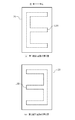
- FIG. 7 is a plan view schematically showing another example of the mounting position of the electronic component in FIG.
- FIG. 1 shows an embodiment of a motor drive control unit according to the present invention, and shows an example applied to a drive control system for a motor that generates a steering assist force in an electric power steering system for a vehicle.
- the electric power steering system 100 is a system that is provided in the vehicle 1 and generates a steering assist force by the motor 110.
- the electric power steering system 100 includes a motor 110, a steering wheel 120, a steering torque sensor 130, a steering angle sensor 140, a drive control unit 150 including an inverter, and a rotation of the motor 110 to reduce the rotation of the motor 110 to a steering shaft 160 (pinion shaft).
- a reduction gear 170 for transmission is included.
- the steering torque sensor 130, the steering angle sensor 140, and the speed reducer 170 are provided in a steering column 180 that includes the steering shaft 160.
- a pinion gear 190 a is provided at the tip of the steering shaft 160, and when the pinion gear 190 a rotates, the rack gear 190 b moves horizontally to the left and right with respect to the traveling direction of the vehicle 1.
- Steering mechanisms 210 for the wheels 200 are provided at both ends of the rack gear 190b, and the direction of the wheels 200 is changed by the horizontal movement of the rack gear 190b.
- the steering torque sensor 130 detects a steering torque generated in the steering shaft 160 when the driver of the vehicle 1 performs a steering operation, and outputs a detected steering torque detection signal ST to the drive control unit 150.
- the steering angle sensor 140 detects the rotation angle of the steering shaft 160 when the driver of the vehicle 1 rotates the steering wheel 120 by performing a steering operation, and drives the detected steering angle detection signal SA. Output to the control unit 150.
- the drive control unit 150 including a microcomputer (arithmetic processing unit) includes information on the state quantity used for determining the steering assist force such as the steering torque signal ST and the steering angle signal SA and the vehicle speed signal VSP output from the vehicle speed sensor 220. Is entered.
- the drive control unit 150 controls the torque generated by the motor 110 based on the driving state of the vehicle 1 such as the steering torque signal ST, the steering angle signal SA, and the vehicle speed signal VSP, thereby assisting in steering in the electric power steering system 100. Control the power.
- the drive control unit 150 is assembled integrally with the motor 110 to constitute the electric unit 230.
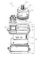
- FIG. 2 is an exploded perspective view of the electric unit 230.
- the motor 110 of the electric unit 230 includes a motor housing 110a in which a stator (stator) (not shown) is fixed, and a rotor (permanent magnet rotor) described later is rotatably held in a space formed in the center of the stator.
- a shaft 110b that is fixed to the rotor and transmits the rotational force to the speed reducer 170, and a motor terminal 110c that electrically connects the drive control unit 150 and a three-phase winding described later wound around the stator. It becomes.
- the shaft 110b is formed as a worm shaft that meshes with the worm wheel of the speed reducer 170.
- the drive control unit 150 of the electric unit 230 includes an inverter board 10 on which an inverter circuit for driving the motor 110 is formed, a control board 20 on which a control circuit for controlling the inverter circuit is formed, and a case 30 formed in a box shape.
- a cover 40 that can be joined to the case 30 in a liquid-tight manner, and an electrical connector that supplies power to each part of the drive control unit 150 from an external power source and inputs various signals. 50.
- the case 30 and the cover 40 constitute a housing having an internal space by bonding. Openings 30 a and 30 b into which the motor 110 and the electrical connector 50 are closely fitted are further formed at the bottom of the case 30. Among these, the motor 110 is fixed in a state in which one end portion in the axial direction is fitted into the opening 30 a and faces the internal space of the housing constituted by the case 30 and the cover 40. The motor terminal 110c of the motor 110 is directly connected to the inverter circuit of the inverter board 10 through the opening 30a.
- the case 30 and the cover 40 are located on the side opposite to the one end of the motor 110, and the control board 20 is located facing the one end of the motor 110 in the internal space of the casing constituted by them.
- the control board 20 and the inverter board 10 are accommodated and fixed in a state where the inverter board 10 is positioned facing the control board 20.
- the control board 20 and the inverter board 10 are arranged side by side inside the casing constituted by the case 30 and the cover 40.
- the motor terminal 110 c may penetrate the control board 20 and be connected to the inverter circuit of the inverter board 10.
- control board 20 for example, a printed board capable of surface mounting of electronic components such as a glass epoxy board is used, but the inverter board 10 is not particularly limited, but heat generated in the inverter circuit is used. In consideration of heat dissipation, a metal substrate can be used.
- the motor 110 and the drive control unit 150 are integrally assembled to form the electric unit 230.
- the motor 110 and the drive control unit 150 are: You may be comprised as a separate unit mutually in the distant position.
- the opening 30 a is not formed in the case 30 of the drive control unit 150, and the motor terminal 110 c is electrically connected to the inverter circuit in the drive control unit 150 via the electrical connector 50.
- FIG. 3 shows an exemplary circuit configuration of the motor 110 and the drive control unit 150.
- the motor 110 includes a first winding set CA composed of three-phase windings UA, VA, WA that are star-connected, and a second winding set CB composed of three-phase windings UB, VB, WB that are also star-connected. Is a three-phase synchronous motor. The point where the three-phase windings UA, VA, WA are connected in the first winding set CA and the point where the three-phase windings UB, VB, WB are connected in the second winding set CB are respectively neutral points. Make.
- the first winding set CA and the second winding set CB are provided in a state of being insulated from each other by a stator (not shown), and the first winding set CA and the second winding set CB share a magnetic circuit. ing. Further, as described above, one rotor 110R is rotatably provided at the center of the stator.
- the drive control unit 150 drives and controls each of the windings UA, VA, and WA of the first winding set CA and each of the windings UB, VB, and WB of the second winding set CB.
- the drive control system of the motor 110 is divided into two. Redundant.
- the steering torque sensor 130 and the steering angle sensor 140 connected to the drive control unit 150 also differ between the first drive control system and the second drive control system, and the first drive control system includes the steering torque sensor 130A and the steering.
- An angle sensor 140A is connected, and a steering torque sensor 130B and a steering angle sensor 140B are connected to the second drive control system.
- the power supply from the power battery 240 is also divided by the electric connector 50 for each drive control system.
- the vehicle speed sensor 220 that outputs the vehicle speed signal VSP to the drive control unit 150 may be shared by the first drive control system and the second drive control system.
- the drive control unit 150 accommodates the inverter board 10 as described above, and the inverter circuit formed on the inverter board 10 includes the first inverter circuit 12A of the first drive control system and the second inverter of the second drive control system. Circuit 12B.
- the inverter board 10 is provided with a power relay 14A and a power relay 14B, and a current sensor 16A and a current sensor 16B.
- the first inverter circuit 12A is connected to the first winding set CA (three-phase windings UA, VA, WA) via the motor terminal 110c, converts the DC power from the power supply battery 240, and is a three-phase winding. AC power is supplied to each of UA, VA, and WA.
- the second inverter circuit 12B is connected to the second winding set CB (three-phase windings UB, VB, WB) via the motor terminal 110c, converts the DC power from the power supply battery 240, and has a three-phase winding. AC power is supplied to the lines UB, VB, and WB, respectively.
- the first inverter circuit 12A includes a three-phase bridge circuit including three sets of semiconductor switches that respectively drive the U-phase winding UA, the V-phase winding VA, and the W-phase winding WA of the first winding set CA.
- the second inverter circuit 12B is a three-phase bridge circuit including three sets of semiconductor switches that respectively drive the U-phase winding UB, the V-phase winding UB, and the W-phase winding WB of the second winding set CB. Consists of.
- a semiconductor switch is an electronic component using a semiconductor that can be switched on and off according to a control signal from the outside, such as a FET (Field Effect Transistor), an IGBT (Insulated Gate Bipolar Transistor), or a bipolar transistor. is there.
- the motor 110 is normally driven by the total output of the two inverter circuits of the first inverter circuit 12A and the second inverter circuit 12B, whereby the motor 110 is required in the electric power steering system 100. Torque corresponding to the steering assist force to be generated is generated.
- the output ratio between the first inverter circuit 12A and the second inverter circuit 12B is set to, for example, 50% vs. 50% during normal times.
- the power relay 14A is provided between the power battery 240 and the first inverter circuit 12A, and is configured to cut off the power supply to the first inverter circuit 12A in a predetermined case.
- the power relay 14B is provided between the power battery 240 and the second inverter circuit 12B, and is configured to cut off the power supply to the second inverter circuit 12B in a predetermined case.
- the power relays 14A and 14B are electronic components using semiconductors that can be switched on and off according to control signals from the outside, like the semiconductor switches of the first inverter circuit 12A and the second inverter circuit 12B. is there.
- the current sensor 16A is connected in series to, for example, the ground-side bus 18mA among the positive-side bus 18pA connecting the power battery 240 and the first inverter circuit 12A and the ground-side bus 18mA connecting the first inverter circuit 12A and the ground.
- This is a current detector provided with a mounted shunt resistor and capable of detecting a potential difference between both ends of the shunt resistor, thereby detecting the energization state of the first inverter circuit 12A.
- the current sensor 16B includes, for example, a shunt resistor interposed in series with the ground-side bus 18mB out of the positive-side bus 18pB and the ground-side bus 18mB. This is a detector, which detects the energization state of the second inverter circuit 12B.
- the drive control unit 150 accommodates the control board 20 facing the inverter board 10 as described above, and the control circuit formed on the control board 20 includes the first control circuit 20A of the first drive control system and the first control circuit 20A. And a second control circuit 20B of a two-drive control system.
- the first control circuit 20A includes a magnetic pole position sensor 22A, a power supply IC (Integrated Circuit) 24A, a microcomputer (first controller) 26A, and a pre-driver (first pre-driver) 28A.
- the second control circuit 20B includes a magnetic pole position sensor 22B, a power supply IC 24B, a microcomputer (second controller) 26B, and a pre-driver (second pre-driver) 28B.
- the configuration of the second control circuit 20B has the same function as the configuration of the first control circuit 20A.
- the magnetic pole position sensor 22A is a position detector that detects the magnetic pole position of the rotor 110R.
- the magnetic pole position sensor 22A outputs a magnetic pole position detection signal corresponding to the magnetic pole position of the rotating rotor 110R to the microcomputer 26A.
- the magnetic pole position sensor 22A is a magnetoresistive element mounted on the control board 20 in the vicinity of the one end portion (rotor 110R) of the motor 110 as an example. It may be a Hall element, a Hall IC, or the like mounted on, or a resolver connected to the shaft 110b of the motor 110.
- the magnetic pole position sensor 22A is not mounted on the control board 20 (for example, when a resolver or the like is used), the positional relationship between the control board 20 and the inverter board 10 with respect to the motor 110 may be switched.
- the power supply IC 24A has a function of receiving power supply from the power supply battery 240 via the electrical connector 50, adjusting the power supply voltage of the power supply battery 20 to the operating voltage of the microcomputer 26A and the magnetic pole position sensor 22A, and supplying this.
- the power supply IC 24A also supplies power to the steering torque sensor 130A and the steering angle sensor 140A disposed outside the drive control unit 150 via the electrical connector 50.
- the microcomputer 26A includes a CPU (Central Processing Unit), a RAM (Random Access Memory), a ROM (Read Only Memory), an input / output interface, a communication interface, and the like. It is comprised so that there may exist the function of. That is, the microcomputer 26A generates the steering assist force required in the electric power steering system 100 based on the steering torque detection signal ST, the steering angle detection signal SA, and the vehicle speed signal VSP input via the electrical connector 50.
- the target current value that is the target output value of the total output of the first inverter circuit 12A and the second inverter circuit 12B is calculated so that the torque of the motor 110 can be generated according to the calculated steering assist force.
- the microcomputer 26A reads the normal output ratio of the first inverter circuit 12A and the second inverter circuit 12B from a memory such as a ROM, corrects the target current value according to the output ratio, and sets the first inverter circuit.
- a corrected target current value that is a target output value in each inverter circuit of 12A and the second inverter circuit 12B is calculated. For example, when the normal output ratio is set to 50% vs. 50%, the microcomputer 26A corrects the target current value to a half value, and a correction target that is the target output value of the first inverter circuit 12A.
- the current value is performed by either the microcomputer 26A or the microcomputer 26B, and the calculated target current value or this and the corrected target current value are sent to the other microcomputer later. You may transmit via the communication line.
- the microcomputer 26A is electrically connected to both ends of the shunt resistor of the current sensor 16A, and based on the potential difference between both ends, the microcomputer 26A is an actual current value that flows through the negative electrode bus 18mA of the first inverter circuit 12A. A current value is calculated, and based on the deviation between the corrected target current value and the actual current value, a duty ratio that is a ratio of time for turning on and off the semiconductor switch of the first inverter circuit 12A by the PWM operation is calculated. Further, the microcomputer 26A calculates the magnetic pole position of the rotor 110R from the magnetic pole position detection signal. Then, the microcomputer 26A outputs a PWM control signal corresponding to the magnetic pole position and the duty ratio.
- the pre-driver 28A is a circuit that drives a semiconductor switch that constitutes a three-phase bridge circuit of the first inverter circuit 12A in response to a command signal (PWM control signal) from the microcomputer 26A.
- the first drive control system controls the first inverter circuit 12A for driving the windings UA, VA, WA of the first winding set CA and the first inverter circuit 12A.
- the second drive control system includes a second inverter circuit 12B that drives the windings UB, VB, and WB of the second winding set CB, and a second inverter circuit 12B that controls the second inverter circuit 12B. 2 control circuit 20B.
- the microcomputer 26A determines whether or not an abnormality has occurred in the first drive control system, such as diagnosing that an overcurrent has occurred when the peak value of the actual current value detected by the current sensor 16A continues for a predetermined time. It has various well-known abnormality diagnosis functions for diagnosing the above.
- the microcomputer 26B has a similar abnormality diagnosis function.
- the microcomputer 26A diagnoses that an abnormality has occurred in the first drive control system
- the power supply relay 14A is immediately turned off via the pre-driver 28A, and the power supply battery 240 to the first inverter circuit 12A. Is interrupted, and the inverter output to the first winding set CA is stopped.
- the microcomputer 26A may stop various calculation processes such as calculation of the target current value and the actual current value.
- a communication line CL is provided between the microcomputer 26A and the microcomputer 26B.
- the microcomputer 26A diagnoses that an abnormality has occurred in the first drive control system
- the microcomputer 26A Immediately outputs status information indicating that an abnormality has occurred in the first drive control system to the microcomputer 26B via the communication line CL.
- the communication line CL is used for other communication applications such as mutual monitoring of both CPUs of the microcomputer 26A and the microcomputer 26B, and data transmission / reception of the target current value or the corrected target current value. Can also be used.
- the microcomputer 26B When the microcomputer 26B corrects the target current value based on the status information received from the microcomputer 26A, the microcomputer 26B sets the inverter output ratio read from the memory such as the ROM to the normal output ratio (for example, 50% to 50%). ) To an output ratio at the time of abnormality (for example, 0% to 100%). When the output ratio at the time of abnormality is set at 0% to 100%, the microcomputer 26B does not correct the target current value and sets the target current value as the target output value of the second inverter circuit 12B.
- the microcomputer 26B diagnoses that an abnormality has occurred in the second drive control system, the abnormal process in the microcomputer 26A and the microcomputer 26B is reversed.
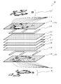
- FIG. 4 is an exploded perspective view schematically showing a multilayer structure of the control board 20.
- the control board 20 is configured such that the first control circuit 20A is located on the front side and the second control circuit 20B is located on the back side.
- the first control circuit 20A is composed of a plurality of layers in which an electronic component is surface-mounted on the surface of the control board 20 and stacked from the surface toward the inside.
- the second control circuit 20B includes a plurality of layers in which electronic components are surface-mounted on the back surface of the control board 20 and stacked from the back surface to the inside.
- the first control circuit 20A and the second control circuit 20B are electrically insulated by a middle insulating layer M except for a part thereof.
- the control substrate 20 forms a multilayer substrate in which a plurality of layers are stacked.
- a first layer L1A, a second layer L2A, a third layer L3A, a fourth layer L4A, and a fifth layer L5A are sequentially stacked from the surface on which the electronic component DA is mounted to the inside.
- the first control circuit layer is formed.
- the second control circuit 20B includes a first layer L1B, a second layer L2B, a third layer L3B, a fourth layer L4B, and a fifth layer L5B in order from the back surface to the inside where the electronic component DB is mounted.
- a stacked second control circuit layer is formed.
- the first layer L1A, the third layer L3A, and the fifth layer L5A are conductive layers formed of a conductor such as copper foil.
- the second layer L2A and the fourth layer L4A are thin plate-like or sheet-like insulating layers formed with an insulating resin (for example, epoxy resin) as a main component, and are formed of the first layer L1A and the third layer L3A.
- the third layer L3A and the fifth layer L5A are electrically insulated.
- the first layer L1A is a mounting pad for surface-mounting the electronic component DA
- the third layer L3A is a conductive pattern constituting a wiring circuit in the first control circuit 20A
- the fifth layer is the control board 20 It is a ground layer that extends across the entire plane.
- the conductive pattern includes not only the third layer L3A but also the mounting pads of the first layer L1A.
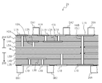
- FIG. 5 is a cross-sectional view showing a three-dimensional wiring structure of the control board 20.
- the mounting pad of the first layer L1A and the conductive pattern of the third layer L3A are filled with, for example, a conductive paste in a blind via penetrating the second layer L2A in the thickness direction of the control board 20 Electrically connected by an interlayer conductive path H1A formed by solidification or the like, and one electronic component DA1 is connected to another electronic component DA2 via the first layer L1A, the third layer L3A and the interlayer conductive path H1A And electrically connected.
- the fifth layer L5A is electrically connected to the first layer L1A or the third layer L3A by interlayer conductive paths H2A and H3A formed between a part of the first layer L1A or a part of the third layer L3A. Can be connected to.
- the first control circuit 20 ⁇ / b> A is three-dimensionally configured on the surface side of the control board 20.
- the microcomputer 26A of the first control circuit 20A and the microcomputer 26B of the second control circuit 20B are electrically connected by a communication line CL.
- an interlayer conductive path HAB that penetrates the control substrate 20 including the insulating layer M is formed from the first layer L1A of the first control circuit 20A to the first layer L1B of the second control circuit 20B.
- the fifth layer L5B which is the ground layer of the first control circuit 20A and the fifth layer L5B which is the ground layer of the second control circuit 20B Are cut out at a portion through which the interlayer conductive path HAB penetrates and its periphery.
- the interlayer conductive path HAB is configured so as not to contact the conductive patterns of the third layers L3A and L3B and the mounting pads on which the microcomputer 26A and the microcomputer 26B of the first layers L1A and L1B are not surface-mounted. Thereby, regarding the electrical relationship between the first control circuit 20A and the second control circuit 20B on the control board 20, the microcomputer 26A and the microcomputer 26B are connected only by the interlayer conductive path HAB. Thus, even when an abnormality occurs in one of the first control circuit 20A and the second control circuit 20B, the influence of the influence on the other can be reduced as much as possible.
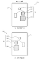
- FIG. 6 is a plan view schematically showing the mounting positions of the electronic components DA and DB on the control board 20.
- the control board 20 is formed in a rectangular shape, and the opposing direction of a set of opposing sides when the control board 20 is viewed from the surface side is a left-right direction as shown in the figure.
- an electronic component DA (typically, a magnetic pole position sensor 22A, a power supply IC 24A, a microcomputer 26A, and a pre-driver 28A are mounted on the surface of the control board 20 of the first control circuit 20A.
- the mounting position of shown
- heat generating components such as the microcomputer 26A and the pre-driver 28A are unevenly distributed on the right side, and the power supply IC 24A that is not a heat generating component is unevenly distributed on the left side. I am doing so.
- the electronic component DB of the second control circuit 20B mounted on the back surface of the control board 20 (typically, a microcomputer 26B, a pre-driver 28B, a magnetic pole position sensor 22B, and a power source
- the mounting position of the IC 24B is seen through the control board 20 from the front side, and heat generating parts (indicated by shading) such as the microcomputer 26B and the pre-driver 28B are unevenly distributed on the left side, and the power supply IC 24B that is not a heat generating part is on the right side Are symmetrical with respect to the mounting position of the electronic component DA of the first control circuit 20A.
- the mounting position of the electronic component DB of the second control circuit 20B is left and right in plan view of the control board 20 with respect to the mounting position of the electronic component DA of the first control circuit 20A in which the heat generating components are unevenly distributed to the right side.
- the mounting pads for the first layer L1A in the first control circuit 20A and the mounting pads for the first layer L1B in the second control circuit 20B are formed so as to be symmetrical. Therefore, the mounting pad of the first layer L1A viewed from the front surface side of the control board 20 and the mounting pad of the first layer L1B viewed from the back surface side of the control board 20 have the same shape.
- the heat generating components of the first control circuit 20A and the heat generating components of the second control circuit 20B are formed.
- the control board 20 is surface-mounted without overlapping in plan view, and in particular, any of the first control circuit 20A and the second control circuit 20B is normal when no abnormality occurs in the first drive control system and the second drive control system.
- the influence of the mutual heat generation between the heat generating component of the first control circuit 20A and the heat generating component of the second control circuit 20B is reduced to suppress the temperature rise of the heat generating component. Yes.
- the mounting pads are the same in the first control circuit 20A and the second control circuit 20B.
- the shape is used to suppress a decrease in design efficiency and thus manufacturing efficiency.
- one control circuit has a plurality of heat generating components such as the first control circuit 20A having a microcomputer 26A and a pre-driver 28A
- the heat generating components are unevenly distributed on one side of the control board 20 as shown in FIG. ) May be replaced with the mounting position as follows.
- the microcomputer 26A is viewed from the front side of the control board 20.
- the pre-driver 28A is unevenly distributed on the left side and the pre-driver 28A is unevenly distributed on the right side, so that a plurality of heat generating components (indicated by shading) are unevenly distributed on the left and right sides, but are not positioned side by side in the left-right direction.
- FIG. 7B the mounting position of the electronic component DB of the second control circuit 20B mounted on the back surface of the control board 20 is seen through the control board 20 from the front side, and the microcomputer 26B.
- the mounting pad of the first layer L1A in the first control circuit 20A and the mounting pad of the first layer L1B in the second control circuit 20B are such that the mounting positions of the electronic components surface-mounted on the respective mounting pads are the control board 20.
- the mounting positions of the heat-generating components that are surface-mounted on the respective mounting pads are formed so as not to overlap with each other in plan view.
- FIG. 8 is a plan view schematically showing the conductive pattern of the third layer L3A in the first control circuit 20A and the conductive pattern of the third layer L3B in the second control circuit 20B.
- the mounting pads are arranged so that the mounting position of the electronic component DB of the second control circuit 20B is symmetrical in plan view with respect to the mounting position of the electronic component DA of the first control circuit 20A. Therefore, the conductive pattern of the third layer L3B in the second control circuit 20B is also formed to be symmetrical with respect to the conductive pattern of the third layer L3A in the first control circuit 20A in plan view of the control board 20. Is done. Therefore, the conductive pattern of the third layer L3A seen through from the front surface side of the control board 20 and the conductive pattern of the third layer L3B seen through from the back surface side of the control board 20 have the same shape.
- the drive control unit 150 of the motor 110 two drive control systems for the motor 110 are made redundant based on the request to the electric power steering system 100 related to the automatic operation of the vehicle 1 and the functional safety. Also, since the first control board 20A is formed on the front surface side of the control board 20 and the second control board 20B is formed on the back surface side of the control board 20, an increase in the board area of the control board 20 can be suppressed. It is possible to relax the restriction on the degree of freedom of the in-vehicle layout without increasing the size of the control unit 150.
- the drive control unit 150 even if the first control circuit 20A and the second control circuit 20B are respectively formed on both surfaces of the control board 20, the heat generating components are mounted so as not to overlap in plan view. It is possible to reduce the thermal deterioration due to the temperature rise of the heat generating components, and to further improve the reliability of the drive control unit 150 and the electric power steering system 100 by making the drive control system of the motor 110 redundant.
- the mounting pad of the first layer L1A and the conductive pattern of the third layer L3A in the first control circuit 20A, and the mounting pad of the first layer L1B and the conductive pattern of the third layer L3B in the second control circuit 20B are controlled. Since the substrate 20 is formed so as to be line symmetric in plan view and has the same shape, it is possible to suppress a decrease in design efficiency and thus manufacturing efficiency, compared to the case of having different mounting pads and conductive patterns.
- the electrical connection between the first control circuit 20A and the second control circuit 2B is a communication line CL for communicating between the microcomputer 26A and the microcomputer 26B. Therefore, even if an abnormality occurs in one of the first control circuit 20A and the second control circuit 20B, the influence on the other can be reduced as much as possible.
- the first layer L1A mounting pad and the third layer L3A conductive pattern in the first control circuit 20A and the first layer L1B mounting pad and the third layer L3A conductive pattern in the second control circuit 20B are axisymmetric in the plan view of the control board 20, and the mounting positions of the heat generating components that are surface-mounted on the respective mounting pads are the plan view. It was formed so as not to overlap.
- the inverter board 10 and the electrical circuit If electrical connection to the connector 50 is not difficult, the mounting pad and conductive pattern constituting the first control circuit 20A and the mounting pad and conductive constituting the second control circuit 20B are replaced with the above-described line symmetrical configuration.
- the pattern may be formed so as to be point symmetric in the plan view of the control board 20.
- the mounting pad of the first layer L1A and the conductive pattern of the third layer L3A in the first control circuit 20A and the second control circuit 20B The mounting pads of the first layer L1B and the conductive patterns of the third layer L3A are not formed so that the mounting positions of the electronic components surface-mounted on the respective mounting pads are axisymmetric in a plan view of the control board 20, Simply, the mounting positions of the heat-generating components that are surface-mounted on the respective mounting pads can be formed so as not to overlap in plan view.
- the drive control unit 150 is configured to cut off the inverter output of the drive control system diagnosed as abnormal and set the inverter output of the drive control system diagnosed as normal to 100% at the time of abnormality. It had been. Instead, the drive control unit 150 normally drives, for example, the motor 110 by setting the output ratio of the first inverter circuit 12A and the second inverter circuit 12B to 100% to 0%, and the first inverter circuit 12A When an abnormality occurs, the output of the first inverter circuit 12A is cut off so that the normal output of the second inverter circuit 12B is 100%, and only the microcomputer 26B that controls the second inverter circuit 12B is operated. be able to. In this case, it is the microcomputer 26B that starts operation after the abnormality diagnosis, and the microcomputer 26A that has stopped operating does not generate heat.
- the first layer in the first control circuit 20A Mounting of L1A mounting pad and conductive pattern of third layer L3A, mounting pad of first layer L1B and conductive pattern of third layer L3A in second control circuit 20B, mounting of heat-generating component surface-mounted on each mounting pad You may form so that a position may overlap in planar view.
- the application target of the drive control unit 150 is not limited to the electric power steering system 100, and any device that controls the drive of the motor 110 including the two winding sets CA and CB may be used. Applicable. For example, when the motor 110 having two winding sets CA and CB is used as the electric actuator of the electric brake system, the drive control unit 150 having two drive control systems can be applied.
Landscapes
- Engineering & Computer Science (AREA)
- Power Engineering (AREA)
- Chemical & Material Sciences (AREA)
- Combustion & Propulsion (AREA)
- Transportation (AREA)
- Mechanical Engineering (AREA)
- Power Steering Mechanism (AREA)
- Inverter Devices (AREA)
Abstract
2つの巻線組を備えたモータを巻線組毎に個別に駆動制御するように、モータの駆動制御系が冗長化されて構成された駆動制御ユニットは、第1巻線組の各巻線を駆動する第1インバータ回路、及び第2巻線組の各巻線を駆動する第2インバータ回路が形成されたインバータ基板と、第1インバータ回路を制御するマイクロコンピュータを含む第1制御回路(20A)、及び第2インバータ回路を制御するマイクロコンピュータを含む第2制御回路(20B)が形成された制御基板(20)と、インバータ基板及び制御基板(20)が内部に並設される筐体と、を有している。そして、制御基板(20)の表面側には第1制御回路(20A)を位置させ、裏面側には第2制御回路(20B)を位置させている。
Description
本発明は、モータを駆動するインバータ回路が形成されたインバータ基板とインバータ回路を制御する制御回路が形成された制御基板とを筐体に収容して構成される、モータの駆動制御ユニットに関し、詳しくは、モータの駆動制御系統を冗長化させたものに関する。
モータの駆動制御ユニットには、例えば、モータを駆動源として操舵補助力を発生させる電動パワーステアリングに適用された場合、車両の自動運転や機能安全等の観点から異常発生時でも電動パワーステアリングの機能を維持するために、モータの駆動制御系統を2つにして冗長化し、2つの巻線組を備えたモータを巻線組毎に個別に駆動制御できるようにした構成が知られている(例えば、特許文献1参照)。このようなモータの駆動制御ユニットでは、2つのインバータ回路が設けられたインバータ基板と、インバータ回路を個別に駆動する2つの制御系統を備えた制御基板と、が対向した状態で筐体に収容されている。
ところで、パワー系のインバータ基板では、インバータ回路を構成する半導体スイッチのモジュール化等により実装密度を向上させることが可能であるので、モータの駆動制御系統を冗長化させても、インバータ基板の面積増大を抑制することは比較的容易である。
しかしながら、信号系の制御基板では、インバータ回路の制御以外に、駆動制御ユニットの適用対象に応じて様々な制御が想定され、インバータ基板と比較するとモジュール化の可能範囲は狭くなる傾向にある。したがって、制御基板では、モータの駆動制御系統を冗長化させると、実装部品点数や配線パターン面積が略比例的に増加するため、制御基板の面積増大を抑制することは比較的困難である。そして、制御基板の面積が増大すると、駆動制御ユニットの体格が大型化してしまい、車載レイアウトの自由度に影響を与えるおそれがある。
本発明は上記問題点に鑑みてなされたものであり、モータの駆動制御系統の冗長化に伴う制御基板の面積増大を抑制した、モータの駆動制御ユニットを提供することを目的とする。
このため、本発明に係るモータの駆動制御ユニットでは、固定子に2つの巻線組を備えたモータを巻線組毎に個別に駆動制御するように構成されていることを前提として、第1の巻線組の各巻線を駆動する第1インバータ回路、及び第2の巻線組の各巻線を駆動する第2インバータ回路が形成されたインバータ基板と、第1インバータ回路を制御する第1制御器を含む第1制御回路、及び第2インバータ回路を制御する第2制御器を含む第2制御回路が形成された制御基板と、インバータ基板及び制御基板が内部に並設される筐体と、を含んで構成され、制御基板の表面及び裏面のうち、一面側には第1制御回路を位置させ、他面側には第2制御回路を位置させている。
本発明に係るモータの駆動制御ユニットによれば、モータの駆動制御系統の冗長化に伴う制御基板の面積増大を抑制することができる。
以下、添付された図面を参照し、本発明を実施するための実施形態について詳細に説明する。
図1は、本発明に係るモータの駆動制御ユニットの一実施形態を示し、車両用の電動パワーステアリングシステムにおいて操舵補助力を発生するモータの駆動制御系に適用した例を示す。
図1は、本発明に係るモータの駆動制御ユニットの一実施形態を示し、車両用の電動パワーステアリングシステムにおいて操舵補助力を発生するモータの駆動制御系に適用した例を示す。
電動パワーステアリングシステム100は、車両1に備えられ、操舵補助力をモータ110によって発生させるシステムである。
電動パワーステアリングシステム100は、モータ110、ステアリングホイール120、操舵トルクセンサ130、操舵角度センサ140、インバータを含む駆動制御ユニット150、及び、モータ110の回転を減速してステアリングシャフト160(ピニオンシャフト)に伝達する減速機170を含んで構成される。
操舵トルクセンサ130、操舵角度センサ140及び減速機170は、ステアリングシャフト160を内包するステアリングコラム180内に設けられる。
電動パワーステアリングシステム100は、モータ110、ステアリングホイール120、操舵トルクセンサ130、操舵角度センサ140、インバータを含む駆動制御ユニット150、及び、モータ110の回転を減速してステアリングシャフト160(ピニオンシャフト)に伝達する減速機170を含んで構成される。
操舵トルクセンサ130、操舵角度センサ140及び減速機170は、ステアリングシャフト160を内包するステアリングコラム180内に設けられる。
ステアリングシャフト160の先端にはピニオンギア190aが設けられていて、このピニオンギア190aが回転すると、ラックギア190bが車両1の進行方向に対して左右に水平移動する。ラックギア190bの両端にはそれぞれ車輪200の操舵機構210が設けられており、ラックギア190bが水平移動することで車輪200の向きが変えられる。
操舵トルクセンサ130は、車両1の運転者がステアリング操作を行うことでステアリングシャフト160に発生する操舵トルクを検出し、検出した操舵トルクの検出信号STを駆動制御ユニット150に出力する。
操舵角度センサ140は、車両1の運転者がステアリング操作を行うことでステアリングホイール120を回転させたときのステアリングシャフト160の回転角度を操舵角度として検出し、検出した操舵角度の検出信号SAを駆動制御ユニット150に出力する。
操舵角度センサ140は、車両1の運転者がステアリング操作を行うことでステアリングホイール120を回転させたときのステアリングシャフト160の回転角度を操舵角度として検出し、検出した操舵角度の検出信号SAを駆動制御ユニット150に出力する。
マイクロコンピュータ(演算処理装置)を備える駆動制御ユニット150には、操舵トルク信号ST及び操舵角度信号SAや、車速センサ220が出力する車速の信号VSPなどの操舵補助力の決定に用いる状態量の情報が入力される。
そして、駆動制御ユニット150は、操舵トルク信号ST、操舵角度信号SA、車速信号VSPなどの車両1の運転状態に基づいてモータ110の発生トルクを制御することで、電動パワーステアリングシステム100における操舵補助力を制御する。本実施形態において、駆動制御ユニット150は、モータ110と一体的に組み立てられて電動ユニット230を構成している。
図2は、電動ユニット230の分解斜視図を示す。
電動ユニット230のモータ110は、図示省略のステータ(固定子)を内部に固定し、後述のロータ(永久磁石回転子)をステータの中央部に形成した空間で回転可能に保持したモータハウジング110aと、ロータに固定されて回転力を減速機170に伝達するシャフト110bと、駆動制御ユニット150とステータに巻き回された後述の3相巻線とを電気的に接続するモータ端子110cと、を含んでなる。シャフト110bは、減速機170のウォームホイールと噛合するウォームシャフトとして形成されている。
電動ユニット230のモータ110は、図示省略のステータ(固定子)を内部に固定し、後述のロータ(永久磁石回転子)をステータの中央部に形成した空間で回転可能に保持したモータハウジング110aと、ロータに固定されて回転力を減速機170に伝達するシャフト110bと、駆動制御ユニット150とステータに巻き回された後述の3相巻線とを電気的に接続するモータ端子110cと、を含んでなる。シャフト110bは、減速機170のウォームホイールと噛合するウォームシャフトとして形成されている。
電動ユニット230の駆動制御ユニット150は、モータ110を駆動するインバータ回路が形成されたインバータ基板10と、インバータ回路を制御する制御回路が形成された制御基板20と、箱状に形成されたケース30と、ケース30と接合可能に形成され、接合によりケース30の開口を液密に塞ぐカバー40と、外部の電源から駆動制御ユニット150の各部へ電源を供給するとともに、各種信号を入力する電気コネクタ50と、を含んでなる。
ケース30及びカバー40は接合により内部空間を有する筐体を構成する。
ケース30の底部には、モータ110及び電気コネクタ50がそれぞれ密接に嵌め込まれる開口部30a,30bがさらに形成されている。このうちモータ110については、軸方向の一端部が開口部30aに嵌め込まれて、ケース30及びカバー40で構成される筐体の内部空間に臨んだ状態で固定される。モータ110のモータ端子110cは、開口部30aを通してインバータ基板10のインバータ回路と直接接続される。
ケース30の底部には、モータ110及び電気コネクタ50がそれぞれ密接に嵌め込まれる開口部30a,30bがさらに形成されている。このうちモータ110については、軸方向の一端部が開口部30aに嵌め込まれて、ケース30及びカバー40で構成される筐体の内部空間に臨んだ状態で固定される。モータ110のモータ端子110cは、開口部30aを通してインバータ基板10のインバータ回路と直接接続される。
また、ケース30及びカバー40は、これらによって構成される筐体の内部空間において、モータ110の前記一端部に面して制御基板20が位置し、かつ、モータ110の前記一端部と反対側で制御基板20に対向してインバータ基板10が位置した状態で、制御基板20及びインバータ基板10を収容・固定するように構成されている。これにより、ケース30及びカバー40で構成される筐体の内部に、制御基板20及びインバータ基板10が並設される。モータ端子110cは、制御基板20を貫通してインバータ基板10のインバータ回路と接続されてもよい。
制御基板20には、例えば、ガラスエポキシ基板等、電子部品の表面実装が可能なプリント基板が用いられるのに対し、インバータ基板10には、特に限定するものではないが、インバータ回路で生じた熱の放熱性を考慮して、金属基板を用いることができる。
なお、本実施形態において、モータ110と駆動制御ユニット150とは、一体的に組み立てられて電動ユニット230を構成するものとしているが、他の実施形態では、モータ110と駆動制御ユニット150とは、離れた位置で互いに別体のユニットとして構成されていてもよい。このような実施形態では、駆動制御ユニット150のケース30には開口部30aが形成されず、モータ端子110cは電気コネクタ50を介して駆動制御ユニット150内のインバータ回路と電気的に接続される。
図3は、モータ110及び駆動制御ユニット150の回路構成の一例を示す。
モータ110は、スター結線される3相巻線UA,VA,WAからなる第1巻線組CAと、同じくスター結線される3相巻線UB,VB,WBからなる第2巻線組CBとを有する3相同期電動機である。第1巻線組CAにおいて3相巻線UA,VA,WAが接続された点、及び第2巻線組CBにおいて3相巻線UB,VB,WBが接続された点は、それぞれ中性点をなす。第1巻線組CA及び第2巻線組CBは、図示省略したステータに互いに絶縁された状態で設けられて、第1巻線組CAと第2巻線組CBとは磁気回路を共有している。また、ステータの中央部には、前述したように、1つのロータ110Rが回転可能に備えられている。
モータ110は、スター結線される3相巻線UA,VA,WAからなる第1巻線組CAと、同じくスター結線される3相巻線UB,VB,WBからなる第2巻線組CBとを有する3相同期電動機である。第1巻線組CAにおいて3相巻線UA,VA,WAが接続された点、及び第2巻線組CBにおいて3相巻線UB,VB,WBが接続された点は、それぞれ中性点をなす。第1巻線組CA及び第2巻線組CBは、図示省略したステータに互いに絶縁された状態で設けられて、第1巻線組CAと第2巻線組CBとは磁気回路を共有している。また、ステータの中央部には、前述したように、1つのロータ110Rが回転可能に備えられている。
駆動制御ユニット150は、第1巻線組CAの各巻線UA,VA,WAを駆動制御する第1駆動制御系と、第2巻線組CBの各巻線UB,VB,WBを駆動制御する第2駆動制御系と、で構成され、車両1の自動運転や機能安全等の要求に応じて異常発生時でも電動パワーステアリングの機能を維持するために、モータ110の駆動制御系統を2つにして冗長化している。そして、駆動制御ユニット150に接続される操舵トルクセンサ130及び操舵角度センサ140についても、第1駆動制御系と第2駆動制御系とで異なり、第1駆動制御系には操舵トルクセンサ130A及び操舵角度センサ140Aが接続され、第2駆動制御系には、操舵トルクセンサ130B及び操舵角度センサ140Bが接続されている。また、電源バッテリ240からの電源供給も電気コネクタ50で駆動制御系統毎に分けられている。ただし、駆動制御ユニット150に対して車速信号VSPを出力する車速センサ220は、第1駆動制御系及び第2駆動制御系で共用としてもよい。
駆動制御ユニット150には前述のようにインバータ基板10が収容され、このインバータ基板10に形成されたインバータ回路は、第1駆動制御系の第1インバータ回路12Aと第2駆動制御系の第2インバータ回路12Bとを有している。また、インバータ基板10には、第1インバータ回路12A及び第2インバータ回路12B以外に、電源リレー14A及び電源リレー14Bと、電流センサ16A及び電流センサ16Bと、が設けられている。
第1インバータ回路12Aは、モータ端子110cを介して第1巻線組CA(3相巻線UA,VA,WA)と接続され、電源バッテリ240からの直流電力を変換して、3相巻線UA,VA,WAへそれぞれ交流電力を供給する。また、第2インバータ回路12Bはモータ端子110cを介して第2巻線組CB(3相巻線UB,VB,WB)と接続され、電源バッテリ240からの直流電力を変換して、3相巻線UB,VB,WBへそれぞれ交流電力を供給する。
第1インバータ回路12Aは、第1巻線組CAのU相巻線UA、V相巻線VA及びW相巻線WAをそれぞれに駆動する3組の半導体スイッチを備えた3相ブリッジ回路からなる。また、第2インバータ回路12Bは、第2巻線組CBのU相巻線UB、V相巻線UB及びW相巻線WBをそれぞれに駆動する3組の半導体スイッチを備えた3相ブリッジ回路からなる。半導体スイッチは、例えば、FET(Field Effect Transistor)、IGBT(Insulated Gate Bipolar Transistor)又はバイポーラトランジスタ等、外部からの制御信号に応じてオン・オフするスイッチ動作が可能な、半導体を用いた電子部品である。
モータ110は、通常時、第1インバータ回路12A及び第2インバータ回路12Bの2つのインバータ回路の合計出力で駆動されるようになっており、これにより、モータ110は、電動パワーステアリングシステム100において要求される操舵補助力に応じたトルクを発生するようになっている。第1インバータ回路12Aと第2インバータ回路12Bとの出力比率は、通常時、例えば、50%対50%に設定される。
電源リレー14Aは、電源バッテリ240と第1インバータ回路12Aとの間に設けられ、所定の場合に、第1インバータ回路12Aへの電源供給を遮断するように構成されている。また、電源リレー14Bは、電源バッテリ240と第2インバータ回路12Bとの間に設けられ、所定の場合に、第2インバータ回路12Bへの電源供給を遮断するように構成されている。電源リレー14A,14Bは、第1インバータ回路12A及び第2インバータ回路12Bの半導体スイッチと同様に、外部からの制御信号に応じてオン・オフするスイッチ動作が可能な、半導体を用いた電子部品である。
電流センサ16Aは、電源バッテリ240と第1インバータ回路12Aとを結ぶ正側母線18pA、及び第1インバータ回路12Aとグランドとを結ぶグランド側母線18mAのうち、例えば、グランド側母線18mAに直列に介装されたシャント抵抗を備え、このシャント抵抗の両端電位差を検出できるようにした電流検出器であり、これにより第1インバータ回路12Aの通電状態を検出している。また、電流センサ16Bは、正側母線18pB及びグランド側母線18mBのうち、例えば、グランド側母線18mBに直列に介装されたシャント抵抗を備え、このシャント抵抗の両端電位差を検出できるようにした電流検出器であり、これにより第2インバータ回路12Bの通電状態を検出している。
駆動制御ユニット150には、前述のようにインバータ基板10と対向して制御基板20が収容され、この制御基板20に形成された制御回路は、第1駆動制御系の第1制御回路20Aと第2駆動制御系の第2制御回路20Bとを有している。第1制御回路20Aは、磁極位置センサ22A、電源IC(Integrated Circuit)24A、マイクロコンピュータ(第1制御器)26A及びプリドライバ(第1プリドライバ)28Aを有している。また、第2制御回路20Bは、磁極位置センサ22B、電源IC24B、マイクロコンピュータ(第2制御器)26B及びプリドライバ(第2プリドライバ)28Bを有している。なお、第2制御回路20Bの構成は、それぞれ、第1制御回路20Aの構成と同様の機能を奏するので、以下、重複する説明を省略する。
磁極位置センサ22Aは、ロータ110Rの磁極位置を検出する位置検出器である。磁極位置センサ22Aは、回転するロータ110Rの磁極位置に応じた磁極位置検出信号をマイクロコンピュータ26Aに出力する。磁極位置センサ22Aは、本実施形態では、一例として、モータ110の前記一端部(ロータ110R)の近傍で制御基板20に実装される磁気抵抗素子であるが、これに限定されず、制御基板20に実装されたホール素子やホールIC等、あるいは、モータ110のシャフト110bに接続されたレゾルバ等であってもよい。なお、磁極位置センサ22Aを制御基板20に実装しない場合(例えば、レゾルバ等を使用する場合)には、モータ110に対する制御基板20とインバータ基板10との位置関係を入れ替えてもよい。
電源IC24Aは、電源バッテリ240から電気コネクタ50を介して電源供給を受け、電源バッテリ20の電源電圧を、マイクロコンピュータ26A及び磁極位置センサ22Aの動作電圧へ調整してこれを供給する機能を有する。また、電源IC24Aは、電気コネクタ50を介して、駆動制御ユニット150の外部に配置される操舵トルクセンサ130A及び操舵角度センサ140Aに対しても、電源を供給している。
マイクロコンピュータ26Aは、CPU(Central Processing Unit)、RAM(Random Access Memory)、ROM(Read Only Memory)、入出力インタフェース、通信インタフェース等を備え、ROM等に保存されたプログラムを実行することで、以下の機能を奏するように構成されている。
すなわち、マイクロコンピュータ26Aは、電気コネクタ50を介して入力した、操舵トルクの検出信号ST、操舵角度の検出信号SA及び車速信号VSPに基づいて、電動パワーステアリングシステム100において要求される操舵補助力を演算し、算出された操舵補助力に応じてモータ110のトルクを発生できるように、第1インバータ回路12A及び第2インバータ回路12Bの合計出力の目標出力値である目標電流値を算出する。そして、マイクロコンピュータ26Aは、第1インバータ回路12A及び第2インバータ回路12Bの通常時の出力比率をROM等のメモリから読み出して、この出力比率に応じて目標電流値を補正し、第1インバータ回路12A及び第2インバータ回路12Bの各インバータ回路における目標出力値である補正目標電流値を算出する。例えば、通常時の出力比率が50%対50%で設定されている場合、マイクロコンピュータ26Aは、目標電流値を半分の値に補正して、第1インバータ回路12Aの目標出力値である補正目標電流値とする。なお、目標電流値又はこれと補正目標電流値の演算は、マイクロコンピュータ26A又はマイクロコンピュータ26Bのいずれか一方で行い、算出された目標電流値又はこれと補正目標電流値を他方のマイクロコンピュータへ後述の通信線を介して送信してもよい。
すなわち、マイクロコンピュータ26Aは、電気コネクタ50を介して入力した、操舵トルクの検出信号ST、操舵角度の検出信号SA及び車速信号VSPに基づいて、電動パワーステアリングシステム100において要求される操舵補助力を演算し、算出された操舵補助力に応じてモータ110のトルクを発生できるように、第1インバータ回路12A及び第2インバータ回路12Bの合計出力の目標出力値である目標電流値を算出する。そして、マイクロコンピュータ26Aは、第1インバータ回路12A及び第2インバータ回路12Bの通常時の出力比率をROM等のメモリから読み出して、この出力比率に応じて目標電流値を補正し、第1インバータ回路12A及び第2インバータ回路12Bの各インバータ回路における目標出力値である補正目標電流値を算出する。例えば、通常時の出力比率が50%対50%で設定されている場合、マイクロコンピュータ26Aは、目標電流値を半分の値に補正して、第1インバータ回路12Aの目標出力値である補正目標電流値とする。なお、目標電流値又はこれと補正目標電流値の演算は、マイクロコンピュータ26A又はマイクロコンピュータ26Bのいずれか一方で行い、算出された目標電流値又はこれと補正目標電流値を他方のマイクロコンピュータへ後述の通信線を介して送信してもよい。
また、マイクロコンピュータ26Aは、電流センサ16Aのシャント抵抗の両端と電気的に接続されて、両端間の電位差に基づいて、第1インバータ回路12Aの負極母線18mAに実際に流れる電流の値である実電流値を算出し、補正目標電流値と実電流値との偏差に基づいて、第1インバータ回路12Aの半導体スイッチをPWM動作でオン・オフさせる時間の割合であるデューティ比を算出する。さらに、マイクロコンピュータ26Aは、磁極位置検出信号からロータ110Rの磁極位置を算出する。そして、マイクロコンピュータ26Aは、磁極位置とデューティ比とに応じたPWM制御信号を出力する。
プリドライバ28Aは、マイクロコンピュータ26Aからの指令信号(PWM制御信号)に応じて第1インバータ回路12Aの3相ブリッジ回路を構成する半導体スイッチを駆動する回路である。
このように、駆動制御ユニット150において、第1駆動制御系は、第1巻線組CAの各巻線UA,VA,WAを駆動する第1インバータ回路12Aと、第1インバータ回路12Aを制御する第1制御回路20Aと、で構成され、第2駆動制御系は、第2巻線組CBの各巻線UB,VB,WBを駆動する第2インバータ回路12Bと、第2インバータ回路12Bを制御する第2制御回路20Bと、で構成されている。
マイクロコンピュータ26Aは、電流センサ16Aにより検出された実電流値のピーク値が所定時間継続したときに過電流が発生していると診断する等、第1駆動制御系について異常が発生しているか否かを診断する種々公知の異常診断機能を有している。マイクロコンピュータ26Bも同様の異常診断機能を有している。
例えば、マイクロコンピュータ26Aが第1駆動制御系に異常が発生していると診断した場合には、プリドライバ28Aを介して電源リレー14Aを直ちにオフにして、電源バッテリ240から第1インバータ回路12Aへの電源供給を遮断し、第1巻線組CAへのインバータ出力を停止させる。このとき、マイクロコンピュータ26Aは、目標電流値・実電流値の演算等、各種の演算処理を中止してもよい。
また、マイクロコンピュータ26Aとマイクロコンピュータ26Bとの間には、通信線CLが設けられており、マイクロコンピュータ26Aが第1駆動制御系に異常が発生していると診断した場合には、マイクロコンピュータ26Aは、直ちに、マイクロコンピュータ26Bに対し、通信線CLを介して、第1駆動制御系に異常が発生している旨のステータス情報を出力する。なお、この通信線CLは、ステータス情報の伝送以外に、マイクロコンピュータ26A及びマイクロコンピュータ26Bの両CPUの相互監視や、目標電流値又はこれと補正目標電流値のデータ送受信等、他の通信用途にも用いられ得る。
マイクロコンピュータ26Bは、マイクロコンピュータ26Aから受けたステータス情報に基づいて、目標電流値を補正する際に、ROM等のメモリから読み出すインバータ出力比率を、通常時の出力比率(例えば、50%対50%)から、異常時の出力比率(例えば、0%対100%)に切り替える。異常時の出力比率が0%対100%で設定されている場合、マイクロコンピュータ26Bは目標電流値を補正せず、目標電流値を第2インバータ回路12Bの目標出力値とする。
なお、マイクロコンピュータ26Bが第2駆動制御系に異常が発生していると診断した場合には、マイクロコンピュータ26A及びマイクロコンピュータ26Bにおける異常時処理が逆になる。
図4は、制御基板20の多層構造を模式的に示す展開斜視図である。
制御基板20は、表面側に第1制御回路20Aが位置し、裏面側に第2制御回路20Bが位置するように構成されている。第1制御回路20Aは、制御基板20の表面に電子部品を表面実装し、表面から内側に向けて積層された複数の層で構成されている。また、第2制御回路20Bは、制御基板20の裏面に電子部品を表面実装し、裏面から内側に向けて積層された複数の層で構成されている。そして、第1制御回路20Aと第2制御回路20Bとは、中間の絶縁層Mによって、一部を除き電気的に絶縁されている。このように制御基板20は複数の層を積層した多層基板を形成している。
制御基板20は、表面側に第1制御回路20Aが位置し、裏面側に第2制御回路20Bが位置するように構成されている。第1制御回路20Aは、制御基板20の表面に電子部品を表面実装し、表面から内側に向けて積層された複数の層で構成されている。また、第2制御回路20Bは、制御基板20の裏面に電子部品を表面実装し、裏面から内側に向けて積層された複数の層で構成されている。そして、第1制御回路20Aと第2制御回路20Bとは、中間の絶縁層Mによって、一部を除き電気的に絶縁されている。このように制御基板20は複数の層を積層した多層基板を形成している。
第1制御回路20Aは、電子部品DAが実装される表面から内側に向けて、順に、第1層L1A、第2層L2A、第3層L3A、第4層L4A及び第5層L5Aが積層された第1制御回路層をなしている。
また、第2制御回路20Bは、電子部品DBが実装される裏面から内側に向けて、順に、第1層L1B、第2層L2B、第3層L3B、第4層L4B及び第5層L5Bが積層された第2制御回路層をなしている。なお、第2制御回路層の各層と第1制御回路層の各層とは、積層順序が同一の層であれば同様であるので、以下、第2制御回路層に関する重複する説明を省略する。
また、第2制御回路20Bは、電子部品DBが実装される裏面から内側に向けて、順に、第1層L1B、第2層L2B、第3層L3B、第4層L4B及び第5層L5Bが積層された第2制御回路層をなしている。なお、第2制御回路層の各層と第1制御回路層の各層とは、積層順序が同一の層であれば同様であるので、以下、第2制御回路層に関する重複する説明を省略する。
第1層L1A、第3層L3A及び第5層L5Aは、銅箔等の導電体で形成された導電層である。第2層L2A及び第4層L4Aは、絶縁性を有する樹脂(例えば、エポキシ樹脂)を主成分として形成された薄板状又はシート状の絶縁層であり、第1層L1Aと第3層L3Aの間、第3層L3Aと第5層L5Aとの間を電気的に絶縁する。
第1層L1Aは、電子部品DAを表面実装するための実装パッドであり、第3層L3Aは、第1制御回路20Aにおける配線回路を構成する導電パターンであり、第5層は制御基板20の平面方向に全域に広がるグランド層である。本実施形態において、導電パターンには、第3層L3Aだけでなく、第1層L1Aの実装パッドも含まれるものとする。
図5は、制御基板20の立体配線構造を示す断面図である。
図5に示すように、第1層L1Aの実装パッドと第3層L3Aの導電パターンとは、例えば、制御基板20の厚さ方向に第2層L2Aを貫通したブラインドビアに導電性ペーストを充填・固化するなどして形成された層間導電路H1Aにより電気的に接続され、1つの電子部品DA1は、第1層L1A、第3層L3A及び層間導電路H1Aを介して、他の電子部品DA2と電気的に接続される。また、第5層L5Aは、第1層L1Aの一部又は第3層L3Aの一部との間で形成された層間導電路H2A,H3Aにより、第1層L1A又は第3層L3Aと電気的に接続され得る。このように、第1制御回路20Aは制御基板20の表面側に立体的に構成されている。
図5に示すように、第1層L1Aの実装パッドと第3層L3Aの導電パターンとは、例えば、制御基板20の厚さ方向に第2層L2Aを貫通したブラインドビアに導電性ペーストを充填・固化するなどして形成された層間導電路H1Aにより電気的に接続され、1つの電子部品DA1は、第1層L1A、第3層L3A及び層間導電路H1Aを介して、他の電子部品DA2と電気的に接続される。また、第5層L5Aは、第1層L1Aの一部又は第3層L3Aの一部との間で形成された層間導電路H2A,H3Aにより、第1層L1A又は第3層L3Aと電気的に接続され得る。このように、第1制御回路20Aは制御基板20の表面側に立体的に構成されている。
ここで、第1制御回路20Aのマイクロコンピュータ26Aと第2制御回路20Bのマイクロコンピュータ26Bとは、図3に示すように、通信線CLで電気的に接続されるが、この通信線CLは、図5に示すように、第1制御回路20Aの第1層L1Aから第2制御回路20Bの第1層L1Bまで絶縁層Mを含む制御基板20を貫通した層間導電路HABにより形成される。このとき、層間導電路HABと第1制御回路20Aのグランド層である第5層L5A及び第2制御回路20Bのグランド層である第5層L5Bとの間で短絡を起こさないように、グランド層は、層間導電路HABが貫通する部分とその周囲が切り欠かれている。また、層間導電路HABは、第3層L3A,L3Bの導電パターンや、第1層L1A,L1Bのうちマイクロコンピュータ26A及びマイクロコンピュータ26Bが表面実装されない実装パッドとは接触しないように構成される。これにより、制御基板20における第1制御回路20Aと第2制御回路20Bとの間の電気的関係については、マイクロコンピュータ26Aとマイクロコンピュータ26Bとが層間導電路HABでのみ接続されるようにすることで、第1制御回路20A及び第2制御回路20Bの一方に異常が発生した場合であっても、他方にその影響が波及することを可及的に低減できるようにしている。
図6は、制御基板20における電子部品DA,DBの実装位置を模式的に示す平面図である。なお、説明の便宜上、制御基板20は矩形に形成されているものとし、制御基板20を表面側から平面視したときの1組の対向辺の対向方向を図示のように左右方向とする。
図6(a)に示すように、制御基板20の表面に実装される、第1制御回路20Aの電子部品DA(代表例として、磁極位置センサ22A、電源IC24A、マイクロコンピュータ26A及びプリドライバ28Aを示す)の実装位置については、制御基板20の表面側からみて、マイクロコンピュータ26A及びプリドライバ28Aなどの発熱部品(網掛けで表示)が右側に偏在し、発熱部品でない電源IC24Aが左側に偏在するようにしている。
そして、図6(b)に示すように、制御基板20の裏面に実装される、第2制御回路20Bの電子部品DB(代表例として、マイクロコンピュータ26B、プリドライバ28B、磁極位置センサ22B及び電源IC24Bを示す)の実装位置を、制御基板20を表面側から透視して、マイクロコンピュータ26B及びプリドライバ28Bなどの発熱部品(網掛けで表示)が左側に偏在し、発熱部品でない電源IC24Bが右側に偏在するように、第1制御回路20Aの電子部品DAの実装位置に対して左右対称にしている。
このように、発熱部品を右側に偏在させた、第1制御回路20Aの電子部品DAの実装位置に対し、第2制御回路20Bの電子部品DBの実装位置が、制御基板20の平面視で左右対称となるように、第1制御回路20Aにおける第1層L1Aの実装パッド、及び第2制御回路20Bにおける第1層L1Bの実装パッドを形成している。したがって、制御基板20の表面側からみた第1層L1Aの実装パッドと制御基板20の裏面側からみた第1層L1Bの実装パッドとは同一の形状を呈する。
電子部品DA,DBの実装位置を図6に示すようにする実装パッドを第1層L1A,L1Bに形成することで、第1制御回路20Aの発熱部品と第2制御回路20Bの発熱部品とが制御基板20の平面視で重畳せずに表面実装され、特に、第1駆動制御系及び第2駆動制御系に異常が発生していない通常時に第1制御回路20A及び第2制御回路20Bのいずれもが動作している場合に、第1制御回路20Aの発熱部品と第2制御回路20Bの発熱部品との間の相互発熱による影響を低減して、発熱部品の温度上昇を抑制するようにしている。
また、電子部品DA,DBの実装位置を図6に示すようにする実装パッドを第1層L1A,L1Bに形成することで、実装パッドを第1制御回路20Aと第2制御回路20Bとで同一形状にして、設計効率ひいては製造効率の低下を抑制するようにしている。
第1制御回路20Aがマイクロコンピュータ26A及びプリドライバ28Aを有するなど、1つの制御回路が複数の発熱部品を有する場合には、制御基板20の左右一方の側に発熱部品を偏在させる図6(a)の実装位置に替えて、以下のようにしてもよい。
すなわち、図7(a)に示すように、制御基板20の表面に実装される、第1制御回路20Aの電子部品DAの実装位置については、制御基板20の表面側からみて、マイクロコンピュータ26Aを左側に偏在させ、プリドライバ28Aを右側に偏在させて、複数の発熱部品(網掛けで表示)が左右一方の側に偏在するが、左右方向で並んで位置しないようにしている。そして、図7(b)に示すように、制御基板20の裏面に実装される、第2制御回路20Bの電子部品DBの実装位置を、制御基板20を表面側から透視して、マイクロコンピュータ26Bが右側に偏在し、プリドライバ28Bが左側に偏在するように、第1制御回路20Aの電子部品DAの実装位置に対して左右対称にする。このような実装位置となるように第1層L1A,第1層L1Bの実装パッドを形成することで、設計効率等の低下を抑制しつつ発熱部品の温度上昇を低減するようすることもできる。
要するに、第1制御回路20Aにおける第1層L1Aの実装パッド、及び第2制御回路20Bにおける第1層L1Bの実装パッドは、それぞれの実装パッドに表面実装される電子部品の実装位置が制御基板20の平面視で線対称となり、かつ、それぞれの実装パッドに表面実装される発熱部品の実装位置が平面視で重畳しないように形成される。
図8は、第1制御回路20Aにおける第3層L3Aの導電パターン、及び第2制御回路20Bにおける第3層L3Bの導電パターンを模式的に示す平面図である。
実装パッドは、図6及び図7に示すように、第2制御回路20Bの電子部品DBの実装位置が第1制御回路20Aの電子部品DAの実装位置に対して平面視で左右対称となるように形成されるので、第2制御回路20Bにおける第3層L3Bの導電パターンも第1制御回路20Aにおける第3層L3Aの導電パターンに対して制御基板20の平面視で左右対称となるように形成される。したがって、制御基板20の表面側から透視した第3層L3Aの導電パターンと制御基板20の裏面側から透視した第3層L3Bの導電パターンとは同一の形状を呈する。
実装パッドは、図6及び図7に示すように、第2制御回路20Bの電子部品DBの実装位置が第1制御回路20Aの電子部品DAの実装位置に対して平面視で左右対称となるように形成されるので、第2制御回路20Bにおける第3層L3Bの導電パターンも第1制御回路20Aにおける第3層L3Aの導電パターンに対して制御基板20の平面視で左右対称となるように形成される。したがって、制御基板20の表面側から透視した第3層L3Aの導電パターンと制御基板20の裏面側から透視した第3層L3Bの導電パターンとは同一の形状を呈する。
かかるモータ110の駆動制御ユニット150によれば、車両1の自動運転や機能安全等に関連する電動パワーステアリングシステム100への要求に基づいて、モータ110の駆動制御系統を2つにして冗長化しても、制御基板20の表面側に第1制御基板20Aを形成し、制御基板20の裏面側に第2制御基板20Bを形成することで、制御基板20の基板面積の増大を抑制できるので、駆動制御ユニット150の体格が大型化することなく、車載レイアウトの自由度に対する制限を緩和することが可能である。
また、駆動制御ユニット150によれば、制御基板20の両面に第1制御回路20Aと第2制御回路20Bとをそれぞれ形成しても、発熱部品が平面視で重畳しないように実装されるので、発熱部品の温度上昇による熱劣化を低減でき、モータ110の駆動制御系統の冗長化による駆動制御ユニット150ひいては電動パワーステアリングシステム100の信頼性をさらに向上させることが可能である。特に、第1制御回路20Aにおける第1層L1Aの実装パッド及び第3層L3Aの導電パターンと、第2制御回路20Bにおける第1層L1Bの実装パッド及び第3層L3Bの導電パターンとが、制御基板20の平面視で線対称となるように形成されて同一形状を有するため、異なる実装パッド及び導電パターンを有する場合よりも、設計効率ひいては製造効率の低下を抑制することができる。
さらに、駆動制御ユニット150によれば、制御基板20において、第1制御回路20Aと第2制御回路2Bとの電気的接続が、マイクロコンピュータ26Aとマイクロコンピュータ26Bとの間で通信を行う通信線CLとしての層間導電路HABだけであることから、第1制御回路20A及び第2制御回路20Bの一方に異常が発生した場合であっても、他方に対する影響を可及的に低減することができる。
なお、前述の実施形態において、第1制御回路20Aにおける第1層L1Aの実装パッド及び第3層L3Aの導電パターンと第2制御回路20Bにおける第1層L1Bの実装パッド及び第3層L3Aの導電パターンとを、それぞれの実装パッドに表面実装される電子部品の実装位置が制御基板20の平面視で線対称となり、かつ、それぞれの実装パッドに表面実装される発熱部品の実装位置が平面視で重畳しないように形成していた。しかし、制御基板20の表面側に位置する第1制御回路20Aと裏面側に位置する第2制御回路20Bとで、インバータ基板10及び電気コネクタ50に対する位置関係が異なっても、インバータ基板10及び電気コネクタ50に対する電気的接続が困難とならない場合には、前述の線対称の構成に替えて、第1制御回路20Aを構成する実装パッド及び導電パターンと第2制御回路20Bを構成する実装パッド及び導電パターンとが、制御基板20の平面視で点対称となるように形成されてもよい。
また、前述の実施形態において、設計効率や製造効率等を無視し得る場合には、第1制御回路20Aにおける第1層L1Aの実装パッド及び第3層L3Aの導電パターンと第2制御回路20Bにおける第1層L1Bの実装パッド及び第3層L3Aの導電パターンとを、それぞれの実装パッドに表面実装される電子部品の実装位置が制御基板20の平面視で線対称となるように形成せず、単に、それぞれの実装パッドに表面実装される発熱部品の実装位置が平面視で重畳しないように形成することができる。
前述の実施形態において、駆動制御ユニット150は、異常時に、異常と診断された駆動制御系のインバータ出力を遮断して、正常と診断された駆動制御系のインバータ出力を100%にするように構成されていた。これに替えて、駆動制御ユニット150が、通常時は、例えば、第1インバータ回路12A及び第2インバータ回路12Bの出力比率を100%対0%としてモータ110を駆動し、第1インバータ回路12Aの異常時に、第1インバータ回路12Aの出力を遮断して、正常な第2インバータ回路12Bの出力を100%にするようにし、第2インバータ回路12Bを制御するマイクロコンピュータ26Bだけが動作するようにすることができる。この場合、異常診断後に発熱するのは、動作を開始するマイクロコンピュータ26Bであり、動作が停止したマイクロコンピュータ26Aは発熱を生じない。
したがって、異常と診断されるまでにマイクロコンピュータ26Bがマイクロコンピュータ26Aから受けた熱を考慮しても、マイクロコンピュータ26Bの温度が許容温度を超えない場合には、第1制御回路20Aにおける第1層L1Aの実装パッド及び第3層L3Aの導電パターンと第2制御回路20Bにおける第1層L1Bの実装パッド及び第3層L3Aの導電パターンとを、それぞれの実装パッドに表面実装される発熱部品の実装位置が平面視で重畳するように形成してもよい。
前述の実施形態において、駆動制御ユニット150の適用対象は電動パワーステアリングシステム100に限定されず、2つの巻線組CA,CBを備えたモータ110を駆動制御するものであれば、いかなるものにも適用可能である。例えば、電動ブレーキシステムの電動アクチュエータとして2つの巻線組CA,CBを備えたモータ110を用いる場合に、2つの駆動制御系統を有する駆動制御ユニット150を適用することができる。
10…インバータ基板、12A…第1インバータ回路、12B…第2インバータ回路、20…制御基板、20A…第1制御回路、20B…第2制御回路、26A…マイクロコンピュータ、26B…マイクロコンピュータ、28A…プリドライバ、28B…プリドライバ、30…ケース、40…カバー、110…モータ、150…駆動制御ユニット、DA…電子部品、DB…電子部品、L1A…実装パッド、L1B…実装パッド、L3A…導電パターン、L3B…導電パターン、L5A…グランド層、L5B…グランド層、M…絶縁層、HAB(CL)…層間導電路(通信線)、CA…第1巻線組(UA,VA,WA)、CB…第2巻線組(UB,VB,WB)
Claims (12)
- 固定子に2つの巻線組を備えたモータを巻線組毎に個別に駆動制御するように構成された、モータの駆動制御ユニットであって、
第1の巻線組の各巻線を駆動する第1インバータ回路、及び第2の巻線組の各巻線を駆動する第2インバータ回路が形成されたインバータ基板と、
前記第1インバータ回路を制御する第1制御器を含む第1制御回路、及び前記第2インバータ回路を制御する第2制御器を含む第2制御回路が形成された制御基板と、
前記インバータ基板及び前記制御基板が内部に並設される筐体と、
を含んで構成され、
前記制御基板の表面及び裏面のうち、一面側には前記第1制御回路を位置させ、他面側には前記第2制御回路を位置させた、
モータの駆動制御ユニット。 - 前記一面側に位置する前記第1制御回路の発熱部品と前記他面側に位置する前記第2制御回路の発熱部品とが、平面視で重畳しないように表面実装されている、請求項1に記載のモータの駆動制御ユニット。
- 前記第1制御回路及び前記第2制御回路は、平面視で線対称となる同一の導電パターンで形成されている、請求項2に記載のモータの駆動制御ユニット。
- 前記制御基板は、前記第1制御回路が形成される第1制御回路層、前記第2制御回路が形成される第2制御回路層、及び前記第1制御回路層と前記第2制御回路層とを電気的に絶縁する絶縁層を含む複数の層を積層した多層基板として形成され、
前記第1制御回路層に表面実装される前記第1制御器と前記第2制御回路層に表面実装される前記第2制御器との間で通信を行う通信線のみが、前記絶縁層を貫通して形成されている、請求項1に記載のモータの駆動制御ユニット。 - 前記制御基板は、前記絶縁層の両側にグランド層が積層されている、請求項4に記載のモータの駆動制御ユニット。
- 前記通信線では、前記第1インバータ回路及び前記第1制御回路を含む第1駆動制御系と前記第2インバータ回路及び前記第2制御回路を含む前記第2駆動制御系とのいずれか一方が異常である場合に、前記第1制御器と前記第2制御器との間で異常が発生している旨のステータス情報が伝送される、請求項4に記載のモータの駆動制御ユニット。
- 前記第1制御回路の発熱部品には第1制御器が含まれ、前記第2制御回路の発熱部品には第2制御器が含まれる、請求項2に記載のモータの駆動制御ユニット。
- 前記第1制御器及び前記第2制御器は、前記第1インバータ回路及び前記第1制御回路を含む第1駆動制御系と前記第2インバータ回路及び前記第2制御回路を含む前記第2駆動制御系とが正常である場合に、前記第1インバータ回路及び前記第2インバータ回路の両方から所定比率で出力させる、請求項2に記載のモータの駆動制御ユニット。
- 前記所定比率は50%対50%である、請求項8に記載のモータの駆動制御ユニット。
- 前記インバータ基板と前記制御基板とが、前記筐体内において対向配置されている、請求項1に記載のモータの駆動制御ユニット。
- 前記筐体には前記モータが嵌め込まれて一体的なユニットを形成する、請求項1に記載のモータの駆動制御ユニット。
- 前記第1制御器及び前記第2制御器は、前記第1インバータ回路及び前記第1制御回路を含む第1駆動制御系と前記第2インバータ回路及び前記第2制御回路を含む前記第2駆動制御系とが正常である場合に、前記第1インバータ回路又は前記第2インバータ回路のいずれか一方から出力させ、前記第1駆動制御系及び前記第2駆動制御系のうち前記一方を含むものに異常が発生した場合に前記一方からの出力を遮断して他方から出力させるように構成された、請求項1に記載のモータの駆動制御ユニット。
Priority Applications (3)
| Application Number | Priority Date | Filing Date | Title |
|---|---|---|---|
| CN201680014890.9A CN107509392B (zh) | 2015-03-12 | 2016-02-25 | 电机的驱动控制单元 |
| US15/557,289 US9991838B2 (en) | 2015-03-12 | 2016-02-25 | Drive control unit for motor |
| DE112016001165.2T DE112016001165B4 (de) | 2015-03-12 | 2016-02-25 | Antriebssteuereinheit für einen Motor |
Applications Claiming Priority (2)
| Application Number | Priority Date | Filing Date | Title |
|---|---|---|---|
| JP2015-049661 | 2015-03-12 | ||
| JP2015049661A JP6427443B2 (ja) | 2015-03-12 | 2015-03-12 | モータの駆動制御ユニット |
Publications (1)
| Publication Number | Publication Date |
|---|---|
| WO2016143534A1 true WO2016143534A1 (ja) | 2016-09-15 |
Family
ID=56880074
Family Applications (1)
| Application Number | Title | Priority Date | Filing Date |
|---|---|---|---|
| PCT/JP2016/055586 Ceased WO2016143534A1 (ja) | 2015-03-12 | 2016-02-25 | モータの駆動制御ユニット |
Country Status (5)
| Country | Link |
|---|---|
| US (1) | US9991838B2 (ja) |
| JP (1) | JP6427443B2 (ja) |
| CN (1) | CN107509392B (ja) |
| DE (1) | DE112016001165B4 (ja) |
| WO (1) | WO2016143534A1 (ja) |
Cited By (1)
| Publication number | Priority date | Publication date | Assignee | Title |
|---|---|---|---|---|
| WO2018207319A1 (ja) | 2017-05-11 | 2018-11-15 | 三菱電機株式会社 | 電子制御装置 |
Families Citing this family (19)
| Publication number | Priority date | Publication date | Assignee | Title |
|---|---|---|---|---|
| JP6472570B2 (ja) * | 2016-03-14 | 2019-02-20 | 三菱電機株式会社 | 電動モータ制御システム及びそれを備えた電動パワーステアリング装置 |
| JP2020537108A (ja) * | 2017-10-10 | 2020-12-17 | ジョンソン コントロールズ テクノロジー カンパニーJohnson Controls Technology Company | チラー電気エンクロージャ用のシステム |
| JP6779193B2 (ja) * | 2017-11-07 | 2020-11-04 | 日立オートモティブシステムズ株式会社 | 電動駆動装置 |
| KR102066221B1 (ko) | 2018-02-08 | 2020-01-14 | 주식회사 만도 | 차량의 조향 장치 및 방법 |
| JP7114968B2 (ja) * | 2018-03-22 | 2022-08-09 | 株式会社デンソー | 電動機駆動装置 |
| CN108528523A (zh) * | 2018-03-29 | 2018-09-14 | 株洲易力达机电有限公司 | 一种双路电动助力转向控制系统及方法 |
| JP6999480B2 (ja) | 2018-04-12 | 2022-01-18 | 日立Astemo株式会社 | 電子制御装置及びその診断方法 |
| JP7147683B2 (ja) * | 2019-05-17 | 2022-10-05 | 株式会社デンソー | 電力変換装置 |
| US11133770B2 (en) * | 2019-06-20 | 2021-09-28 | Delta Electronics, Inc. | Motor drive system and control method therefor |
| JP7361789B2 (ja) * | 2019-11-18 | 2023-10-16 | 三菱電機株式会社 | 回転電機装置および電動パワーステアリング装置 |
| WO2021106941A1 (ja) * | 2019-11-25 | 2021-06-03 | アイシン・エィ・ダブリュ株式会社 | 制御基板 |
| JP7310566B2 (ja) * | 2019-11-25 | 2023-07-19 | 株式会社アイシン | 回転電機の制御基板 |
| KR102859298B1 (ko) * | 2020-03-17 | 2025-09-12 | 현대모비스 주식회사 | 전동 조향 장치의 파워팩 |
| DE102020121931A1 (de) | 2020-08-21 | 2022-02-24 | Liebherr-Aerospace Lindenberg Gmbh | Redundanter Antrieb |
| KR20230061550A (ko) | 2020-12-15 | 2023-05-08 | 히다치 아스테모 가부시키가이샤 | 모터 제어 장치 및 모터 제어 시스템 |
| JP6981605B1 (ja) * | 2021-02-04 | 2021-12-15 | 佐川電子株式会社 | ギアボックス装置及びエアガン |
| CN118285159A (zh) | 2021-12-17 | 2024-07-02 | Exro技术公司 | 用于电源逆变器的物品及电源逆变器 |
| US20250373188A1 (en) | 2022-07-22 | 2025-12-04 | Hitachi Astemo, Ltd. | Motor control apparatus and motor control system |
| WO2024134750A1 (ja) * | 2022-12-20 | 2024-06-27 | 三菱電機株式会社 | 電子制御装置および電動パワーステアリング装置 |
Citations (3)
| Publication number | Priority date | Publication date | Assignee | Title |
|---|---|---|---|---|
| JP2013086718A (ja) * | 2011-10-20 | 2013-05-13 | Jtekt Corp | 電動パワーステアリング装置 |
| WO2014010061A1 (ja) * | 2012-07-12 | 2014-01-16 | 三菱電機株式会社 | 車載モータ駆動用制御基板 |
| JP2014090030A (ja) * | 2012-10-29 | 2014-05-15 | Jtekt Corp | 制御装置および同装置を備える車両操舵装置 |
Family Cites Families (12)
| Publication number | Priority date | Publication date | Assignee | Title |
|---|---|---|---|---|
| JP4187308B2 (ja) * | 1998-06-16 | 2008-11-26 | 日本オーチス・エレベータ株式会社 | 可変速駆動装置 |
| JP2001257419A (ja) * | 2000-03-10 | 2001-09-21 | Nec Corp | 波長安定化レーザモジュール |
| DE10053818B4 (de) * | 2000-10-30 | 2006-03-30 | Sauer-Danfoss Holding Aps | Elektrisches Lenksystem |
| JP3970798B2 (ja) * | 2003-04-18 | 2007-09-05 | Necアクセステクニカ株式会社 | 液晶モニタ装置 |
| JP4821452B2 (ja) * | 2006-06-20 | 2011-11-24 | 富士電機株式会社 | 超小型電力変換装置およびその製造方法 |
| DE102006033175A1 (de) * | 2006-07-18 | 2008-01-24 | Robert Bosch Gmbh | Elektronikanordnung |
| JP5516066B2 (ja) * | 2009-06-24 | 2014-06-11 | 株式会社デンソー | 駆動装置 |
| JP5435286B2 (ja) * | 2009-06-24 | 2014-03-05 | 株式会社デンソー | 駆動装置 |
| JP5435284B2 (ja) * | 2009-06-24 | 2014-03-05 | 株式会社デンソー | 駆動装置 |
| JP5012953B2 (ja) * | 2010-05-21 | 2012-08-29 | 株式会社デンソー | 駆動装置 |
| JP5807846B2 (ja) * | 2012-03-29 | 2015-11-10 | 株式会社デンソー | 駆動装置 |
| CN103580584B (zh) * | 2013-09-24 | 2016-02-17 | 上海华菱电站成套设备有限公司 | 矿井提升机双绕组同步电机的冗余中压交直交变频装置 |
-
2015
- 2015-03-12 JP JP2015049661A patent/JP6427443B2/ja active Active
-
2016
- 2016-02-25 US US15/557,289 patent/US9991838B2/en active Active
- 2016-02-25 CN CN201680014890.9A patent/CN107509392B/zh active Active
- 2016-02-25 DE DE112016001165.2T patent/DE112016001165B4/de active Active
- 2016-02-25 WO PCT/JP2016/055586 patent/WO2016143534A1/ja not_active Ceased
Patent Citations (3)
| Publication number | Priority date | Publication date | Assignee | Title |
|---|---|---|---|---|
| JP2013086718A (ja) * | 2011-10-20 | 2013-05-13 | Jtekt Corp | 電動パワーステアリング装置 |
| WO2014010061A1 (ja) * | 2012-07-12 | 2014-01-16 | 三菱電機株式会社 | 車載モータ駆動用制御基板 |
| JP2014090030A (ja) * | 2012-10-29 | 2014-05-15 | Jtekt Corp | 制御装置および同装置を備える車両操舵装置 |
Cited By (2)
| Publication number | Priority date | Publication date | Assignee | Title |
|---|---|---|---|---|
| WO2018207319A1 (ja) | 2017-05-11 | 2018-11-15 | 三菱電機株式会社 | 電子制御装置 |
| US11131720B2 (en) | 2017-05-11 | 2021-09-28 | Mitsubishi Electric Corporation | Electronic control device |
Also Published As
| Publication number | Publication date |
|---|---|
| US20180062556A1 (en) | 2018-03-01 |
| US9991838B2 (en) | 2018-06-05 |
| DE112016001165B4 (de) | 2019-11-14 |
| DE112016001165T5 (de) | 2017-11-23 |
| CN107509392A (zh) | 2017-12-22 |
| JP2016171664A (ja) | 2016-09-23 |
| CN107509392B (zh) | 2020-05-22 |
| JP6427443B2 (ja) | 2018-11-21 |
Similar Documents
| Publication | Publication Date | Title |
|---|---|---|
| CN107509392B (zh) | 电机的驱动控制单元 | |
| JP7094371B2 (ja) | 電動パワーステアリング装置 | |
| JP6940358B2 (ja) | 回路基板、モータ駆動装置および電動パワーステアリング装置 | |
| JP7188285B2 (ja) | 電源システム | |
| US11387716B2 (en) | Redundant circuit device | |
| US11904958B2 (en) | Detection device, calculation device, control device, and electric power steering device using the same | |
| CN112039408B (zh) | 电力转换装置 | |
| WO2015087554A1 (ja) | 電子制御ユニット、電動パワーステアリング装置及び車両 | |
| JP2017189033A (ja) | 駆動装置、および、これを用いた電動パワーステアリング装置 | |
| JP2020171103A (ja) | 回転電機制御装置、および、これを用いた電動パワーステアリング装置 | |
| JP7160012B2 (ja) | 電子制御装置 | |
| JP2020072621A (ja) | 駆動装置、および、これを用いた電動パワーステアリング装置 | |
| JP5915635B2 (ja) | 電子制御ユニット、電動パワーステアリング装置、車両及び電子制御ユニットの製造方法 | |
| JP7167857B2 (ja) | 電動ステアリング装置 | |
| JP2019201500A (ja) | 回転電機制御装置 | |
| JP7361789B2 (ja) | 回転電機装置および電動パワーステアリング装置 | |
| JP2018537065A (ja) | 冗長電子サブシステムを備えた電気機械式アクチュエータ | |
| WO2024134750A1 (ja) | 電子制御装置および電動パワーステアリング装置 |
Legal Events
| Date | Code | Title | Description |
|---|---|---|---|
| 121 | Ep: the epo has been informed by wipo that ep was designated in this application |
Ref document number: 16761505 Country of ref document: EP Kind code of ref document: A1 |
|
| WWE | Wipo information: entry into national phase |
Ref document number: 15557289 Country of ref document: US |
|
| WWE | Wipo information: entry into national phase |
Ref document number: 112016001165 Country of ref document: DE |
|
| 122 | Ep: pct application non-entry in european phase |
Ref document number: 16761505 Country of ref document: EP Kind code of ref document: A1 |