WO2016143497A1 - 電流制御装置 - Google Patents
電流制御装置 Download PDFInfo
- Publication number
- WO2016143497A1 WO2016143497A1 PCT/JP2016/055125 JP2016055125W WO2016143497A1 WO 2016143497 A1 WO2016143497 A1 WO 2016143497A1 JP 2016055125 W JP2016055125 W JP 2016055125W WO 2016143497 A1 WO2016143497 A1 WO 2016143497A1
- Authority
- WO
- WIPO (PCT)
- Prior art keywords
- input
- vehicle
- control device
- current control
- signal
- Prior art date
- Legal status (The legal status is an assumption and is not a legal conclusion. Google has not performed a legal analysis and makes no representation as to the accuracy of the status listed.)
- Ceased
Links
Images

Classifications
-
- B—PERFORMING OPERATIONS; TRANSPORTING
- B60—VEHICLES IN GENERAL
- B60R—VEHICLES, VEHICLE FITTINGS, OR VEHICLE PARTS, NOT OTHERWISE PROVIDED FOR
- B60R16/00—Electric or fluid circuits specially adapted for vehicles and not otherwise provided for; Arrangement of elements of electric or fluid circuits specially adapted for vehicles and not otherwise provided for
- B60R16/02—Electric or fluid circuits specially adapted for vehicles and not otherwise provided for; Arrangement of elements of electric or fluid circuits specially adapted for vehicles and not otherwise provided for electric constitutive elements
-
- B—PERFORMING OPERATIONS; TRANSPORTING
- B60—VEHICLES IN GENERAL
- B60R—VEHICLES, VEHICLE FITTINGS, OR VEHICLE PARTS, NOT OTHERWISE PROVIDED FOR
- B60R21/00—Arrangements or fittings on vehicles for protecting or preventing injuries to occupants or pedestrians in case of accidents or other traffic risks
- B60R21/01—Electrical circuits for triggering passive safety arrangements, e.g. airbags, safety belt tighteners, in case of vehicle accidents or impending vehicle accidents
- B60R21/017—Electrical circuits for triggering passive safety arrangements, e.g. airbags, safety belt tighteners, in case of vehicle accidents or impending vehicle accidents including arrangements for providing electric power to safety arrangements or their actuating means, e.g. to pyrotechnic fuses or electro-mechanic valves
Definitions
- the present invention relates to a current control device that controls a current flowing through a current path.
- the vehicle is equipped with a power supply system (see, for example, Patent Document 1) that supplies power from a battery to a load.
- the power supply system described in Patent Document 1 is equipped with a current control device.
- the current control device controls power feeding from the battery to the plurality of loads by controlling a current flowing in a current path from the battery to a plurality of loads such as an engine system and a power window.
- the current control device allows current to flow from the battery to multiple loads when the vehicle engine starts. Thereby, a plurality of loads are supplied with power.
- the current control device cuts off current flowing from the battery to the plurality of loads when the engine of the vehicle is stopped. As a result, power supply to a plurality of loads is stopped.
- the engine starts when the ignition switch is on, and stops when the ignition switch is off.
- a current control device is connected from a battery to an electric power steering, an ABS (Anti-lock Braking System), and There are power supply systems that allow current to flow through a plurality of loads such as winkers.
- the current control device cuts off the power supply from the battery to the plurality of loads, and the load stops operating.
- a plurality of loads such as electric power steering, ABS, and winker are important loads related to safety.
- an important load related to safety for example, power supply to the power steering is stopped while the vehicle is traveling, the assist function of the steering operation is lost, and the driver feels the weight of the steering operation. Therefore, when power supply to an important load related to safety is stopped while the vehicle is traveling, a change in operation feeling is given to the driver. The change in the operational feeling gives the driver a feeling of impatience or discomfort.
- the present invention has been made in view of such circumstances, and an object of the present invention is to provide a current control device that does not give the driver a change in operational feeling while the vehicle is traveling. is there.
- a current control device is mounted on a vehicle and controls a current flowing in a current path.
- a first input unit to which an ignition signal indicating ON or OFF of an ignition switch of the vehicle is input;
- a second input unit to which a traveling signal indicating whether the vehicle is traveling or stopped is input, a switch provided in the current path, and the ignition signal input to the first input unit are on.
- a control circuit that turns on the switch when the travel signal input to the second input unit indicates travel of the vehicle.
- the device is mounted on a vehicle and controls the current flowing through the current path.
- An ignition signal indicating whether the ignition switch of the vehicle is on or off is input to the first input unit, and a travel signal indicating whether the vehicle is traveling or stopped is input to the second input unit.
- a switch is provided in a current path from a battery to an important load related to safety. The control circuit turns on the switch when the ignition signal input to the first input unit indicates ON, or when the travel signal input to the second input unit indicates vehicle travel.
- the control circuit indicates that the ignition signal input to the first input unit is OFF, and the travel signal input to the second input unit is a stop of the vehicle. Is turned off, the switch is turned off.
- the control circuit turns off the switch when the ignition signal input to the first input unit indicates OFF and the traveling signal input to the second input unit indicates stop of the vehicle. To do. For this reason, when a switch is provided in the current path from the battery to an important load related to safety, power supply to the load is stopped in a state where safety is ensured.
- the current control device further includes an integration unit that integrates the travel signal input to the second input unit and outputs an integral value, and the vehicle is traveling in the second input unit. During this time, a pulse is repeatedly input as the running signal, and the control circuit indicates that the ignition signal input to the first input unit is on, or the integrated value output by the integrating unit is greater than or equal to a threshold value. In this case, the switch is turned on.
- a pulse is repeatedly input to the second input unit as a traveling signal.
- the integrating unit integrates the running signal and outputs an integrated value. Since the pulse is repeatedly input to the second input unit while the vehicle is traveling, the integration value output by the integration unit is equal to or greater than the threshold value.
- the control circuit turns on the switch when the ignition signal input to the first input unit indicates ON or the integrated value output by the integrating unit is equal to or greater than the threshold value. For this reason, the switch is appropriately turned on and off with a simple configuration.
- the integration unit includes a capacitor that stores electricity when a pulse of the travel signal is input to the second input unit, and a resistor connected in parallel to the capacitor, The integral value is a voltage value across the capacitor.
- the integrating unit has a capacitor and a resistor connected in parallel to the capacitor.
- the capacitor stores power when a pulse of the travel signal is input to the second input unit.
- the running signal is integrated.
- the voltage value across the capacitor is the integral value.
- the voltage value across the capacitor is equal to or greater than the threshold value.
- the control circuit turns on the switch while the ignition signal input to the first input unit indicates ON or the voltage value across the capacitor of the integrating unit is equal to or greater than the threshold value.
- the switch since the switch is turned on while the vehicle is traveling, the driver does not change the operational feeling.
- FIG. 1 is a block diagram showing a main configuration of a power supply system 2 mounted on a vehicle 1 according to the present embodiment.
- the power supply system 2 is preferably mounted on the vehicle 1.
- the power supply system 2 includes a current control device 20, a battery 21, a load 22, an ignition switch 23, a wheel speed sensor 24, and a resistor R1.
- the current control device 20 is connected to the positive electrode of the battery 21 and one end of the load 22.
- the negative electrode of the battery 21 and the other end of the load 22 are grounded.
- the current control device 20 is connected to one end of each of the ignition switch 23 and the resistor R1.
- the other end of the ignition switch 23 is connected to the positive electrode of the battery 21.
- the other end of the resistor R1 is grounded.
- the current control device 20 is connected to one end of the wheel speed sensor 24. The other end of the wheel speed sensor 24 is grounded.
- the load 22 is an in-vehicle device such as an electric power steering, ABS, airbag or winker, and is an important load related to safety. Power is supplied to the load 22 from the battery 21 via the current control device 20.
- the ignition switch 23 When the ignition switch 23 is on, the engine (not shown) of the vehicle 1 starts. When the ignition switch 23 is on, the output voltage of the battery 21 is input to the current control device 20. When the ignition switch 23 is turned off, the engine of the vehicle 1 is stopped. When the ignition switch 23 is off, zero volts is input to the current controller 20.
- the first threshold value Vth1 (see FIG. 3) that is less than the output voltage of the battery 21 and exceeds zero volts is set.
- the ignition signal is equal to or higher than the first threshold value Vth1, it is indicated that the ignition switch 23 is on.
- the ignition switch 23 is off.
- the wheel speed sensor 24 repeatedly outputs pulses to the current control device 20 while the vehicle 1 is traveling. The faster the wheel speed, the narrower the pulse width of the repetitive pulse train output from the wheel speed sensor 24 and the shorter the interval between pulses. Further, the slower the wheel speed, the wider the pulse width of the repeated pulse train output from the wheel speed sensor 24 and the longer the interval between pulses. While the wheel is stopped, that is, while the vehicle 1 is stopped, the wheel speed sensor 24 does not output a pulse to the current control device 20, and a voltage of zero volts is applied from the wheel speed sensor 24 to the current control device 20. Entered. The wheel speed sensor 24 operates regardless of whether the ignition switch 23 is on or off.
- the wheel speed sensor 24 is used for calculating the speed of the vehicle 1. For example, the number of pulses output from the wheel speed sensor 24 during a predetermined period is counted, and the speed of the vehicle 1 is calculated based on the counted number.
- a traveling signal indicating whether the vehicle 1 is traveling or is stopped is input from the wheel speed sensor 24 to the current control device 20.
- the travel signal indicates travel of the vehicle 1.
- a pulse is not repeatedly input from the wheel speed sensor 24 to the current control device 20, Indicates the stop of the vehicle 1.
- the current control device 20 controls the current flowing in the current path from the battery 21 to the load 22 based on the ignition signal and the traveling signal input to the current control device 20.
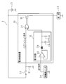
- FIG. 2 is a circuit diagram showing a main configuration of the current control device 20.
- the current control device 20 includes an N-channel FET (Field-Effect-Transistor) 30, an OR circuit 31, and an integration circuit 32.
- the OR circuit 31 has two input terminals and one output terminal. Regarding the FET 30, the drain is connected to the positive electrode of the battery 21, the source is connected to one end of the load 22, and the gate is connected to the output terminal of the OR circuit 31.
- One input terminal of the OR circuit 31 is connected to one end of each of the ignition switch 23 and the resistor R1.
- the other input terminal of the OR circuit 31 is connected to one end of the integrating circuit 32.
- the other end of the integrating circuit 32 is connected to one end of the wheel speed sensor 24.
- the traveling signal is input from the wheel speed sensor 24 to the integrating circuit 32.
- the integration circuit 32 integrates the input travel signal and outputs an integration value (voltage value) to the other input terminal of the OR circuit 31. While the vehicle 1 is traveling, pulses are repeatedly input as traveling signals from the wheel speed sensor 24 to the integrating circuit 32. Therefore, when the vehicle 1 is traveling, the integrated value output from the integrating circuit 32 is large. Further, when the vehicle 1 is stopped, zero volt is input from the wheel speed sensor 24 to the integration circuit 32, so that the integration value output by the integration circuit 32 is small.
- the integration circuit 32 functions as a second input unit and an integration unit.
- the ignition signal is input to one input terminal of the OR circuit 31, and the integration value output from the integration circuit 32 is input to the other input terminal of the OR circuit 31.
- the OR circuit 31 since the OR circuit 31 has one input terminal to which an ignition signal is input, it functions as a first input unit.
- the ignition signal input to one input terminal is greater than or equal to the first threshold Vth1, or the integral value input to the other input terminal is greater than or equal to the second threshold Vth2 (see FIG. 3).
- a high level voltage is output from the output terminal to the gate of the FET 30.
- the OR circuit 31 has a low level when the ignition signal input to one input terminal is less than the first threshold value Vth1 and the integral value input to the other input terminal is less than the second threshold value Vth2. A voltage is output from the output terminal to the gate of the FET 30.
- the integration value output by the integration circuit 32 is equal to or greater than the second threshold value Vth2, and when the travel signal indicates the stop of the vehicle 1, the integration output by the integration circuit 32.
- the value is less than the second threshold value Vth2.
- the integral value output by the integration circuit 32 being equal to or greater than the second threshold value Vth2 means that the travel signal indicates the travel of the vehicle 1, and the integral value output by the integration circuit 32. Being less than the second threshold value Vth2 means that the travel signal indicates that the vehicle 1 is stopped.
- FET 30 functions as a switch. When the voltage applied to the gate of the FET 30 is equal to or higher than a certain voltage, a current can flow between the drain and the gate of the FET 30 and the FET 30 is on. When the voltage applied to the gate of the FET 30 is less than a certain voltage, no current flows between the drain and the gate of the FET 30 and the FET 30 is off. The FET 30 is provided in the current path from the battery 21 to the load 22.
- the OR circuit 31 When the OR circuit 31 outputs a high level voltage from the output terminal to the gate of the FET 30, the voltage applied to the gate of the FET 30 is equal to or higher than a certain voltage, and the FET 30 is on. When the OR circuit 31 outputs a low level voltage from the output terminal to the gate of the FET 30, the voltage applied to the gate of the FET 30 is less than a certain voltage, and the FET 30 is off. As described above, the OR circuit 31 turns the FET 30 on and off by outputting high-level and low-level voltages to the gate of the FET 30.
- the ignition signal input to one input terminal of the OR circuit 31 indicates that the ignition switch 23 is turned on, or the travel signal input to the integration circuit 32 is the travel of the vehicle 1. Is turned on, the FET 30 is turned on.
- the OR circuit 31 Turn off.
- the OR circuit 31 also functions as a control circuit.
- the integrating circuit 32 includes an operational amplifier 40, a capacitor C4, a diode D4, and a resistor R4.
- One end of the wheel speed sensor 24 is connected to the plus terminal of the operational amplifier 40, and the output terminal of the operational amplifier 40 is connected to the minus terminal of the operational amplifier 40.
- the output terminal of the operational amplifier 40 is further connected to the anode of the diode.
- the cathode of the diode D4 is connected to the other input terminal of the OR circuit 31 and one end of each of the capacitor C4 and the resistor R4.
- the other ends of the capacitor C4 and the resistor R4 are grounded.
- the resistor R4 is connected in parallel with the capacitor C4.
- the operational amplifier 40 connected as described above functions as a so-called voltage follower circuit.
- the input impedance of the operational amplifier 40 is high, and the output impedance of the operational amplifier 40 is low.
- the operational amplifier 40 is an ideal operational amplifier, the input impedance of the operational amplifier 40 is infinite and the output impedance of the operational amplifier 40 is zero ohms.
- the output impedance of the wheel speed sensor 24 is high.
- the operational amplifier 40 converts the output impedance of the wheel speed sensor 24 into a low impedance using the above-described characteristics.
- a traveling signal is input from the wheel speed sensor 24 to the plus terminal of the operational amplifier 40.
- the amplification factor of the operational amplifier 40 is 1 time. For this reason, the operational amplifier 40 outputs the traveling signal input from the wheel speed sensor 24 to the plus terminal as it is from the output terminal toward the diode D4 in a state where the output impedance is low. Therefore, when a pulse is input from the wheel speed sensor 24 to the plus terminal of the operational amplifier 40, the operational amplifier 40 outputs the pulse from the output terminal toward the diode D4.
- the capacitor C4 stores electricity.
- the capacitor C4 stores the electric charge when the pulse of the running signal is input to the plus terminal of the operational amplifier 40, and integrates the running signal.
- the voltage value across the capacitor C4 is output to the other input terminal of the OR circuit 31.
- the voltage value between both ends of the capacitor C4 is an integrated value output from the integrating circuit 32.
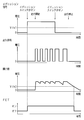
- FIG. 3 is a timing chart for explaining the operation of the current control device 20.
- FIG. 3 shows the waveforms of the ignition signal and the traveling signal, the transition of the integral value output from the integration circuit 32, and the transition of the FET 30 on and off.
- each of the ignition signal and the running signal is zero volts.
- the ignition signal is a voltage less than the first threshold value Vth1
- the integration value output from the integration circuit 32 is less than the second threshold value Vth2.
- the ignition switch 23 when the ignition switch 23 is switched from OFF to ON while the vehicle 1 is stopped, the ignition signal becomes a voltage equal to or higher than the first threshold value Vth1. Thereby, the OR circuit 31 turns on the FET 30 and the load 22 is supplied with power from the battery 21. Since the vehicle 1 is stopped, the travel signal is zero volts, and the integrated value output by the integrating circuit 32 is zero volts.
- the ignition signal becomes a voltage less than the first threshold Vth1, that is, zero volts, but the integration circuit 32 has a wheel speed.
- a pulse is repeatedly input from the sensor 24 as a running signal. For this reason, the integration value output from the integration circuit 32 is equal to or greater than the second threshold value Vth2.
- the OR circuit 31 turns on the FET 30.
- the FET 30 is on and the load 22 is supplied with power from the battery 21. Therefore, while the vehicle 1 is traveling, no change in operation feeling is given to the driver. As described above, when the vehicle 1 is traveling, the voltage value across the capacitor C4 is equal to or higher than the threshold value Vth2.
- the driver of the vehicle 1 can operate a handle (not shown) of the vehicle 1 when the vehicle 1 is traveling with the ignition switch 23 turned off. Avoid obstacles.
- FIG. 3 shows an example in which when the ignition switch 23 is turned off, the speed of the vehicle 1 decreases, the pulse width of the travel signal becomes wider, and the interval between pulses becomes longer.
- the power supply to the load 22 is stopped in a state where the ignition switch 23 is off and the vehicle 1 is stopped, that is, in a state where safety is ensured.
- the vehicle 1 stops and no pulse is repeatedly input to the integration circuit 32, current flows from the capacitor C4 to the resistor R4, the capacitor C4 is discharged, and the voltage value across the capacitor is the second value. It becomes less than the threshold value Vth2.
- the operation of the current control device 20 performed when the vehicle 1 travels in a state where the ignition switch 23 is off is not shown in FIG. Even when the vehicle 1 travels with the ignition switch 23 turned off, pulses are repeatedly transmitted from the wheel speed sensor 24 to the integration circuit 32 in the same manner as when the ignition switch 23 is turned off while the vehicle is traveling. Since it is input, the integration value output from the integration circuit 32 is equal to or higher than the second threshold value Vth2, and the OR circuit 31 turns on the FET 30. As a result, the load 22 is supplied with power from the battery 21.
- the FET 30 is appropriately turned on and off with a simple configuration using the ignition signal and the integrated value output from the integrating circuit 32.
- the number of loads 22 to which the battery 21 supplies power via the FET 30 is not limited to one and may be two or more.
- electric power steering, ABS, airbag, winker, etc. may be supplied with power from the battery 21 via the FET 30.
- the integrating circuit 32 is not limited to a circuit using the operational amplifier 40, the capacitor C4, the diode D4, and the resistor R4, and may be any circuit that can integrate the running signal.
- the travel signal is not limited to the signal output from the wheel speed sensor 24 as long as it is a signal indicating whether the vehicle 1 is traveling or stopped.
- a signal output from an acceleration sensor that detects the acceleration of the vehicle 1 may be used.
- the FET 30 is turned on when the ignition signal input to the current control device 20 indicates that the ignition switch 23 is turned on, or when the travel signal input to the current control device 20 indicates that the vehicle 1 is traveling.
- the FET 30 is turned off when the ignition signal input to the current control device 20 indicates that the ignition switch 23 is turned off and the traveling signal input to the current control device 20 indicates that the vehicle 1 is stopped. .
- the FET 30 since the FET 30 only needs to function as a switch, the FET 30 is not limited to an N-channel FET, and may be a P-channel FET. Further, instead of the FET 30, for example, a bipolar transistor may be used.
Landscapes
- Engineering & Computer Science (AREA)
- Mechanical Engineering (AREA)
- Electronic Switches (AREA)
Abstract
車両が走行している間、運転者に操作感覚の変化を与えることがない電流制御装置を提供する。 電流制御装置20は車両に搭載される。電流制御装置20には、車両のイグニッションスイッチ23のオン又はオフを示すイグニッション信号と、車両が走行しているか又は停止しているかを示す走行信号が入力される。OR回路31は、電流制御装置20に入力されたイグニッション信号がイグニッションスイッチ23のオンを示すか、又は、電流制御装置20に入力された走行信号が車両の走行を示す場合、FET30をオンにする。
Description
本発明は、電流経路を流れる電流を制御する電流制御装置に関する。
車両には、バッテリから負荷に給電される電源システム(例えば、特許文献1参照)が搭載されている。特許文献1に記載の電源システムには電流制御装置が搭載されている。電流制御装置は、バッテリからエンジンシステム及びパワーウィンドウ等の複数の負荷への電流経路に流れる電流を制御することによって、バッテリから複数の負荷への給電を制御する。
電流制御装置は、車両のエンジンが始動した場合、バッテリから複数の負荷に電流が流れることを可能にする。これにより、複数の負荷は給電される。また、電流制御装置は、車両のエンジンが停止した場合、バッテリから複数の負荷に流れる電流を遮断する。これにより、複数の負荷への給電が停止される。
通常、エンジンは、イグニッションスイッチがオンである場合に始動し、イグニッションスイッチがオフとなった場合に停止する。
特許文献1に記載してあるような従来の電源システムの中には、イグニッションスイッチがオンとなった場合に、電流制御装置が、バッテリから、電動パワーステアリング、ABS(Anti-lock Braking System)及びウィンカー等の複数の負荷に電流が流れることを可能にする電源システムがある。この電源システムでは、イグニッションスイッチがオフとなった場合、電流制御装置はバッテリから複数の負荷への給電を遮断し、負荷は動作を停止する。
特許文献1に記載してあるような従来の電源システムの中には、イグニッションスイッチがオンとなった場合に、電流制御装置が、バッテリから、電動パワーステアリング、ABS(Anti-lock Braking System)及びウィンカー等の複数の負荷に電流が流れることを可能にする電源システムがある。この電源システムでは、イグニッションスイッチがオフとなった場合、電流制御装置はバッテリから複数の負荷への給電を遮断し、負荷は動作を停止する。
電動パワーステアリング、ABS及びウィンカー等の複数の負荷夫々は安全に関わる重要な負荷である。車両が走行している間に安全に係る重要な負荷、例えばパワーステアリングへの給電が停止した場合、ステアリング操作のアシスト機能がなくなり、運転者はステアリング操作に重さを感じる。従って、車両が走行している間に安全に係る重要な負荷への給電が停止した場合、運転者に操作感覚の変化が与えられる。操作感覚の変化は運転者に焦り又は違和感等を与える。
イグニッションスイッチがオフである場合に車両が停止しているとは限らない。イグニッションスイッチがオフであるにも関わらず、車両が走行している場合においては、運転者に操作感覚の変化を極力与えないことが望ましい。
本発明は斯かる事情に鑑みてなされたものであり、その目的とするところは、車両が走行している間、運転者に操作感覚の変化を与えることがない電流制御装置を提供することにある。
本発明に係る電流制御装置は、車両に搭載され、電流経路に流れる電流を制御する電流制御装置において、前記車両のイグニッションスイッチのオン又はオフを示すイグニッション信号が入力される第1入力部と、前記車両が走行しているか又は停止しているかを示す走行信号が入力される第2入力部と、前記電流経路に設けられたスイッチと、前記第1入力部に入力された前記イグニッション信号がオンを示すか、又は、前記第2入力部に入力された前記走行信号が前記車両の走行を示す場合、前記スイッチをオンにする制御回路とを備えることを特徴とする。
本発明にあっては、装置は、車両に搭載されており、電流経路に流れる電流を制御する。車両のイグニッションスイッチのオン又はオフを示すイグニッション信号が第1入力部に入力され、車両が走行しているか又は停止しているかを示す走行信号が第2入力部に入力される。例えば、バッテリから、安全に関わる重要な負荷への電流経路にスイッチが設けられている。制御回路は、第1入力部に入力されたイグニッション信号がオンを示すか、又は、第2入力部に入力された走行信号が車両の走行を示す場合、スイッチをオンにする。
このため、たとえイグニッションスイッチがオフであっても、車両が走行している場合、スイッチはオンであり、負荷はバッテリから給電される。従って、車両が走行している間、運転者に操作感覚の変化を与えることはない。
本発明に係る電流制御装置は、前記制御回路は、前記第1入力部に入力された前記イグニッション信号がオフを示し、かつ、前記第2入力部に入力された前記走行信号が前記車両の停止を示す場合、前記スイッチをオフにすることを特徴とする。
本発明にあっては、制御回路は、第1入力部に入力されたイグニッション信号がオフを示し、かつ、第2入力部に入力された走行信号が車両の停止を示す場合、スイッチをオフにする。このため、バッテリから安全に関わる重要な負荷への電流経路にスイッチが設けられている場合において、安全が確保された状態で負荷への給電が停止される。
本発明に係る電流制御装置は、前記第2入力部に入力された走行信号を積分し、積分値を出力する積分部を更に備え、前記第2入力部には、前記車両が走行している間、前記走行信号としてパルスが繰り返し入力され、前記制御回路は、前記第1入力部に入力された前記イグニッション信号がオンを示すか、又は、前記積分部が出力した積分値が閾値以上である場合、前記スイッチをオンにすることを特徴とする。
本発明にあっては、車両が走行している間、走行信号として、パルスが第2入力部に繰り返し入力される。積分部は、走行信号を積分し、積分値を出力する。車両が走行している間、第2入力部にパルスが繰り返し入力されるため、積分部が出力する積分値は閾値以上である。制御回路は、第1入力部に入力されたイグニッション信号がオンを示すか、又は、積分部が出力した積分値が閾値以上である場合、スイッチをオンにする。
このため、簡単な構成でスイッチのオン及びオフが適正に行われる。
このため、簡単な構成でスイッチのオン及びオフが適正に行われる。
本発明に係る電流制御装置は、前記積分部は、前記第2入力部に前記走行信号のパルスが入力された場合に蓄電するコンデンサと、該コンデンサに並列に接続された抵抗とを有し、前記積分値は前記コンデンサの両端間の電圧値であることを特徴とする。
本発明にあっては、積分部はコンデンサとコンデンサに並列に接続された抵抗とを有する。コンデンサは、走行信号のパルスが第2入力部に入力された場合に蓄電する。これにより、走行信号が積分される。コンデンサの両端間の電圧値が積分値である。車両が走行している場合、コンデンサの両端間の電圧値は閾値以上である。車両が停止して第2入力部にパルスが繰り返し入力されていない場合、電流がコンデンサから抵抗へ流れ、コンデンサは放電し、コンデンサの両端間の電圧値は閾値未満となる。制御回路は、第1入力部に入力されたイグニッション信号がオンを示すか、又は、積分部が有するコンデンサの両端間の電圧値が閾値以上である間、スイッチをオンにする。
本発明によれば、車両が走行している間、スイッチがオンにされているため、運転者に操作感覚の変化を与えることはない。
以下、本発明をその実施の形態を示す図面に基づいて詳述する。
図1は本実施の形態における車両1に搭載された電源システム2の要部構成を示すブロック図である。電源システム2は好適に車両1に搭載されている。電源システム2は、電流制御装置20、バッテリ21、負荷22、イグニッションスイッチ23、車輪速センサ24及び抵抗R1を備える。電流制御装置20はバッテリ21の正極と、負荷22の一端とに接続されている。バッテリ21の負極と負荷22の他端とは接地されている。
図1は本実施の形態における車両1に搭載された電源システム2の要部構成を示すブロック図である。電源システム2は好適に車両1に搭載されている。電源システム2は、電流制御装置20、バッテリ21、負荷22、イグニッションスイッチ23、車輪速センサ24及び抵抗R1を備える。電流制御装置20はバッテリ21の正極と、負荷22の一端とに接続されている。バッテリ21の負極と負荷22の他端とは接地されている。
また、電流制御装置20は、イグニッションスイッチ23及び抵抗R1夫々の一端に接続されている。イグニッションスイッチ23の他端はバッテリ21の正極に接続されている。抵抗R1の他端は接地されている。更に、電流制御装置20は、車輪速センサ24の一端に接続されている。車輪速センサ24の他端は接地されている。
負荷22は、電動パワーステアリング、ABS、エアバッグ又はウィンカー等の車載機器であり、安全に関わる重要な負荷である。負荷22には、電流制御装置20を介して、バッテリ21から給電される。
イグニッションスイッチ23がオンである場合に車両1の図示しないエンジンは始動する。イグニッションスイッチ23がオンである場合、バッテリ21の出力電圧が電流制御装置20に入力される。イグニッションスイッチ23がオフとなった場合に車両1のエンジンは停止する。イグニッションスイッチ23がオフである場合、ゼロボルトが電流制御装置20に入力される。
イグニッションスイッチ23のオン及びオフが行われるため、バッテリ21の出力電圧とゼロボルトとによって構成されるイグニッション信号が電流制御装置20に入力される。
バッテリ21の出力電圧未満であって、ゼロボルトを超える第1閾値Vth1(図3参照)が設定されている。イグニッション信号が第1閾値Vth1以上である場合、イグニッションスイッチ23がオンであることが示されている。イグニッション信号が第1閾値Vth1未満である場合、イグニッションスイッチ23がオフであることが示されている。
車輪速センサ24は、車両1が走行している間、パルスを繰り返し電流制御装置20に出力する。車輪の速度が速い程、車輪速センサ24が出力する繰り返しパルス列のパルス幅が狭くてパルス間の間隔が短い。また、車輪の速度が遅い程、車輪速センサ24が出力する繰り返しパルス列のパルス幅が広くてパルス間の間隔が長い。車輪が止まっている間、即ち、車両1が停止している間、車輪速センサ24はパルスを電流制御装置20に出力することはなく、ゼロボルトの電圧が車輪速センサ24から電流制御装置20に入力される。車輪速センサ24は、イグニッションスイッチ23のオン及びオフに無関係に作動している。
車輪速センサ24は車両1の速度を算出するために使用される。例えば、所定期間に車輪速センサ24から出力されるパルスの数をカウントし、カウントした数に基づいて車両1の速度が算出される。
以上のように、電流制御装置20には、車輪速センサ24から、車両1が走行しているか否か又は停止しているかを示す走行信号が入力される。車輪速センサ24からパルスが電流制御装置20に繰り返し入力されている場合、走行信号は車両1の走行を示し、車輪速センサ24からパルスが電流制御装置20に繰り返し入力されていない場合、走行信号は車両1の停止を示す。
電流制御装置20は、自身に入力されるイグニッション信号及び走行信号に基づいて、バッテリ21から負荷22への電流経路に流れる電流を制御する。
図2は電流制御装置20の要部構成を示す回路図である。電流制御装置20は、Nチャネル型のFET(Field Effect Transistor)30、OR回路31及び積分回路32を有する。OR回路31は2つの入力端子と1つの出力端子とを有する。FET30に関して、ドレインはバッテリ21の正極に接続されており、ソースは負荷22の一端に接続されており、ゲートはOR回路31の出力端子に接続されている。OR回路31の一方の入力端子は、イグニッションスイッチ23及び抵抗R1夫々の一端に接続されている。OR回路31の他方の入力端子は積分回路32の一端に接続されている。積分回路32の他端は車輪速センサ24の一端に接続されている。
積分回路32には車輪速センサ24から走行信号が入力される。積分回路32は、入力された走行信号を積分し、積分値(電圧値)をOR回路31の他方の入力端子に出力する。車両1が走行している間、車輪速センサ24から積分回路32に、走行信号としてパルスが繰り返し入力される。従って、車両1が走行している場合、積分回路32が出力する積分値が大きい。また、車両1が停止している場合、車輪速センサ24から積分回路32にゼロボルトが入力されるので、積分回路32が出力する積分値は小さい。積分回路32は、第2入力部及び積分部として機能する。
OR回路31の一方の入力端子にはイグニッション信号が入力され、OR回路31の他方の入力端子には積分回路32が出力した積分値が入力される。以上のように、OR回路31は、イグニッション信号が入力される一方の入力端子を有するので、第1入力部として機能する。
OR回路31は、一方の入力端子に入力されたイグニッション信号が第1閾値Vth1以上であるか、又は、他方の入力端子に入力された積分値が第2閾値Vth2(図3参照)以上である場合に、ハイレベルの電圧を出力端子からFET30のゲートに出力する。
OR回路31は、一方の入力端子に入力されたイグニッション信号が第1閾値Vth1未満であり、かつ、他方の入力端子に入力された積分値が第2閾値Vth2未満である場合に、ローレベルの電圧を出力端子からFET30のゲートに出力する。
走行信号が車両1の走行を示している場合、積分回路32が出力する積分値は第2閾値Vth2以上であり、走行信号が車両1の停止を示している場合、積分回路32が出力する積分値は第2閾値Vth2未満である。言い換えると、積分回路32が出力している積分値が第2閾値Vth2以上であることは、走行信号が車両1の走行を示していることを意味し、積分回路32が出力している積分値が第2閾値Vth2未満であることは走行信号が車両1の停止を示していることを意味する。
FET30はスイッチとして機能する。FET30のゲートに印加されている電圧が一定電圧以上である場合、FET30のドレイン及びゲート間に電流が流れることが可能であり、FET30はオンである。FET30のゲートに印加されている電圧が一定電圧未満である場合、FET30のドレイン及びゲート間に電流が流れることはなく、FET30はオフである。FET30は、バッテリ21から負荷22への電流経路に設けられている。
OR回路31が出力端子からFET30のゲートにハイレベルの電圧を出力した場合、FET30のゲートに印加されている電圧は一定電圧以上であり、FET30はオンである。OR回路31が出力端子からFET30のゲートにローレベルの電圧を出力した場合、FET30のゲートに印加されている電圧は一定電圧未満であり、FET30はオフである。このように、OR回路31は、FET30のゲートにハイレベル及びローレベルの電圧を出力することによって、FET30のオン及びオフを行う。
以上のように、OR回路31は、OR回路31の一方の入力端子に入力されたイグニッション信号がイグニッションスイッチ23のオンを示すか、又は、積分回路32に入力された走行信号が車両1の走行を示す場合、FET30をオンにする。OR回路31は、OR回路31の一方の入力端子に入力されたイグニッション信号がイグニッションスイッチ23のオフを示し、かつ、積分回路32に入力された走行信号が車両1の停止を示す場合、FET30をオフにする。OR回路31は制御回路としても機能する。
積分回路32は、オペアンプ40、コンデンサC4、ダイオードD4及び抵抗R4を有する。オペアンプ40のプラス端子に車輪速センサ24の一端が接続されており、オペアンプ40のマイナス端子にはオペアンプ40の出力端子が接続されている。オペアンプ40の出力端子は更にダイオードのアノードに接続されている。ダイオードD4のカソードは、OR回路31の他方の入力端子と、コンデンサC4及び抵抗R4夫々の一端とに接続されている。コンデンサC4及び抵抗R4夫々の他端は接地されている。このように、抵抗R4はコンデンサC4に並列に接続されている。
以上のように接続されたオペアンプ40は、所謂ボルテージフォロワー回路として機能する。オペアンプ40の入力インピーダンスは高く、オペアンプ40の出力インピーダンスは低い。オペアンプ40が理想的なオペアンプである場合、オペアンプ40の入力インピーダンスは無限大であり、オペアンプ40の出力インピーダンスはゼロオームである。
車輪速センサ24の出力インピーダンスは高い。オペアンプ40は、前述した特性を用いて、車輪速センサ24の出力インピーダンスを低いインピーダンスに変換する。
オペアンプ40のプラス端子には車輪速センサ24から走行信号が入力される。オペアンプ40の増幅率は1倍である。このため、オペアンプ40は、車輪速センサ24からプラス端子に入力された走行信号を、出力インピーダンスが低い状態で、そのまま出力端子からダイオードD4に向けて出力する。従って、車輪速センサ24からオペアンプ40のプラス端子にパルスが入力した場合、オペアンプ40は出力端子からパルスをダイオードD4に向けて出力する。
オペアンプ40が出力端子からパルスを出力した場合、ダイオードD4を介して、コンデンサC4の両端間に電圧が印加され、コンデンサC4は蓄電する。このように、コンデンサC4は、走行信号のパルスがオペアンプ40のプラス端子に入力された場合に蓄電し、走行信号を積分する。コンデンサC4の両端間の電圧値はOR回路31の他方の入力端子に出力される。コンデンサC4の両端間の電圧値は、積分回路32が出力する積分値である。
コンデンサC4は、両端間に電圧が印加されていない場合、即ち、車両1が走行を停止してオペアンプ40のプラス端子にパルスが入力されていない場合、コンデンサC4の一端から抵抗R4を介して電流が流れ、コンデンサC4は放電する。ダイオードD4はコンデンサC4の一端からオペアンプ40の出力端子に電流が流れることを防止する。
図3は電流制御装置20の動作を説明するためのタイミングチャートである。図3には、イグニッション信号及び走行信号の波形と、積分回路32が出力する積分値の推移と、FET30のオン及びオフの推移とが示されている。
イグニッションスイッチ23がオフであり、かつ、車両1が停止している場合、イグニッション信号及び走行信号夫々はゼロボルトである。このとき、イグニッション信号は第1閾値Vth1未満の電圧であり、積分回路32が出力する積分値は第2閾値Vth2未満である。このため、OR回路31はFET30をオフにする。
次に、車両1が停止している状態でイグニッションスイッチ23がオフからオンに切替わった場合、イグニッション信号は第1閾値Vth1以上の電圧となる。これにより、OR回路31はFET30をオンにし、負荷22はバッテリ21から給電される。なお、車両1が停止しているため、走行信号はゼロボルトであり、積分回路32が出力する積分値はゼロボルトである。
次に、イグニッションスイッチ23がオンである状態で車両1が走行を開始した場合、車輪速センサ24から、走行信号としてパルスが積分回路32に繰り返し入力され、積分回路32が出力する積分値、即ち、コンデンサC4の両端間の電圧値が第2閾値Vth2以上となる。このとき、イグニッション信号が第1閾値Vth1以上であり、かつ、積分回路32が出力する積分値が第2閾値Vth2以上であるため、OR回路31はFET30をオンにする。
車輪速センサ24から繰り返し入力されるパルス間の期間、コンデンサC4の一端から抵抗R4に電流が流れ、コンデンサC4は放電し、コンデンサC4の両端間の電圧値は徐々に低下する。このとき、電圧値が低下する速度は、抵抗R4の抵抗値と、コンデンサC4の容量値とから算出される時定数によって決まる。
次に、イグニッションスイッチ23がオフになったにも関わらず、車両1が走行している場合、イグニッション信号は第1閾値Vth1未満の電圧、即ち、ゼロボルトとなるが、積分回路32には車輪速センサ24から走行信号としてパルスが繰り返し入力される。このため、積分回路32が出力する積分値は第2閾値Vth2以上である。このとき、OR回路31はFET30をオンにする。
このため、たとえイグニッションスイッチ23がオフであっても、車両1が走行している場合、FET30はオンであり、負荷22はバッテリ21から給電される。従って、車両1が走行している間、操作感覚の変化を運転者に与えることはない。
以上のように、車両1が走行している場合、コンデンサC4の両端間の電圧値は閾値Vth2以上である。
以上のように、車両1が走行している場合、コンデンサC4の両端間の電圧値は閾値Vth2以上である。
負荷22が電動パワーステアリングである場合において、イグニッションスイッチ23がオフである状態で車両1が走行しているときに、車両1の運転者は、車両1の図示しないハンドルを操作することができるので、障害物を避けることができる。
なお、図3では、イグニッションスイッチ23がオフとなった場合に、車両1の速度が低下し、走行信号のパルス幅が広くなってパルス間の間隔が長くなった例が示されている。
イグニッションスイッチ23がオフである状態で車両が停止した場合、積分回路32には車輪速センサ24から走行信号としてパルスが繰り返し入力されないため、積分回路32のコンデンサC4は放電をし続け、積分回路32が出力する積分値は低下し続ける。イグニッションスイッチ23がオフである状態で積分回路32が出力している積分値が第2閾値Vth2未満となった場合、イグニッション信号は第1閾値未満であるので、OR回路31はFET30をオフにする。
従って、電流制御装置20では、イグニッションスイッチ23がオフであって、車両1が停止している状態、即ち、安全が確保された状態で負荷22への給電が停止される。
以上のように、車両1が停止して積分回路32にパルスが繰り返し入力されていない場合、電流がコンデンサC4から抵抗R4へ流れ、コンデンサC4は放電し、コンデンサの両端間の電圧値は第2閾値Vth2未満となる。
以上のように、車両1が停止して積分回路32にパルスが繰り返し入力されていない場合、電流がコンデンサC4から抵抗R4へ流れ、コンデンサC4は放電し、コンデンサの両端間の電圧値は第2閾値Vth2未満となる。
イグニッションスイッチ23がオフである状態で車両1が走行した場合に行われる電流制御装置20の動作は図3に示されていない。イグニッションスイッチ23がオフである状態で車両1が走行した場合も、車両が走行している状態でイグニッションスイッチ23がオフとなった場合と同様に、車輪速センサ24から積分回路32にパルスが繰り返し入力されるので、積分回路32が出力する積分値は第2閾値Vth2以上となり、OR回路31はFET30をオンにする。これにより、負荷22はバッテリ21から給電される。
以上のように構成された電流制御装置20では、イグニッション信号と、積分回路32が出力した積分値とが用いられた簡単な構成でFET30のオン及びオフが適正に行われる。
なお、バッテリ21がFET30を介して給電する負荷22の数は1つに限定されず、2つ以上であってもよい。例えば、電動パワーステアリング、ABS、エアバッグ及びウィンカー等がバッテリ21からFET30を介して給電されてもよい。
積分回路32は、オペアンプ40、コンデンサC4、ダイオードD4及び抵抗R4を用いた回路に限定されず、走行信号を積分することが可能な回路であればよい。
また、走行信号は、車両1が走行しているか又は停止しているかを示す信号であればよいため、車輪速センサ24から出力される信号に限定されない。走行信号として、例えば、車両1の加速度を検出する加速度センサから出力される信号を用いてもよい。この場合においても、電流制御装置20に入力されたイグニッション信号がイグニッションスイッチ23のオンを示すか、又は、電流制御装置20に入力された走行信号が車両1の走行を示すとき、FET30はオンとなる。同様の場合において、電流制御装置20に入力されたイグニッション信号がイグニッションスイッチ23のオフを示し、かつ、電流制御装置20に入力された走行信号が車両1の停止を示すとき、FET30はオフとなる。
更に、FET30は、スイッチとして機能すればよいため、Nチャネル型のFETに限定されず、Pチャネル型のFETであってもよい。また、FET30の代わりに、例えばバイポーラトランジスタを用いてもよい。
開示された実施の形態は、全ての点で例示であって制限的なものではないと考えられるべきである。本発明の範囲は上述の説明ではなく請求の範囲によって示され、請求の範囲と均等の意味及び範囲内での全ての変更が含まれることが意図される。
1 車両
20 電流制御装置
23 イグニッションスイッチ
30 FET(スイッチ)
31 OR回路(第1入力部、制御回路)
32 積分回路(第2入力部、積分部)
C4 コンデンサ
R4 抵抗
20 電流制御装置
23 イグニッションスイッチ
30 FET(スイッチ)
31 OR回路(第1入力部、制御回路)
32 積分回路(第2入力部、積分部)
C4 コンデンサ
R4 抵抗
Claims (4)
- 車両に搭載され、電流経路に流れる電流を制御する電流制御装置において、
前記車両のイグニッションスイッチのオン又はオフを示すイグニッション信号が入力される第1入力部と、
前記車両が走行しているか又は停止しているかを示す走行信号が入力される第2入力部と、
前記電流経路に設けられたスイッチと、
前記第1入力部に入力された前記イグニッション信号がオンを示すか、又は、前記第2入力部に入力された前記走行信号が前記車両の走行を示す場合、前記スイッチをオンにする制御回路と
を備えることを特徴とする電流制御装置。 - 前記制御回路は、前記第1入力部に入力された前記イグニッション信号がオフを示し、かつ、前記第2入力部に入力された前記走行信号が前記車両の停止を示す場合、前記スイッチをオフにすること
を特徴とする請求項1に記載の電流制御装置。 - 前記第2入力部に入力された走行信号を積分し、積分値を出力する積分部を更に備え、
前記第2入力部には、前記車両が走行している間、前記走行信号としてパルスが繰り返し入力され、
前記制御回路は、前記第1入力部に入力された前記イグニッション信号がオンを示すか、又は、前記積分部が出力した積分値が閾値以上である場合、前記スイッチをオンにすること
を特徴とする請求項1又は請求項2に記載の電流制御装置。 - 前記積分部は、
前記第2入力部に前記走行信号のパルスが入力された場合に蓄電するコンデンサと、
該コンデンサに並列に接続された抵抗と
を有し、
前記積分値は前記コンデンサの両端間の電圧値であること
を特徴とする請求項3に記載の電流制御装置。
Applications Claiming Priority (2)
| Application Number | Priority Date | Filing Date | Title |
|---|---|---|---|
| JP2015-046141 | 2015-03-09 | ||
| JP2015046141A JP2016165939A (ja) | 2015-03-09 | 2015-03-09 | 電流制御装置 |
Publications (1)
| Publication Number | Publication Date |
|---|---|
| WO2016143497A1 true WO2016143497A1 (ja) | 2016-09-15 |
Family
ID=56879053
Family Applications (1)
| Application Number | Title | Priority Date | Filing Date |
|---|---|---|---|
| PCT/JP2016/055125 Ceased WO2016143497A1 (ja) | 2015-03-09 | 2016-02-23 | 電流制御装置 |
Country Status (2)
| Country | Link |
|---|---|
| JP (1) | JP2016165939A (ja) |
| WO (1) | WO2016143497A1 (ja) |
Families Citing this family (1)
| Publication number | Priority date | Publication date | Assignee | Title |
|---|---|---|---|---|
| JP7233888B2 (ja) * | 2018-11-07 | 2023-03-07 | 新電元工業株式会社 | 車両用制御装置、車両および車両用制御装置の制御方法 |
Citations (4)
| Publication number | Priority date | Publication date | Assignee | Title |
|---|---|---|---|---|
| JPS51142357A (en) * | 1975-06-03 | 1976-12-07 | Fujitsu Ten Ltd | Correction method of fuel cost meter |
| JPH1199889A (ja) * | 1997-09-30 | 1999-04-13 | Tokico Ltd | 車両用電子式制御装置 |
| JP2009056920A (ja) * | 2007-08-31 | 2009-03-19 | Mitsubishi Motors Corp | 車両の制御装置 |
| JP2012011887A (ja) * | 2010-06-30 | 2012-01-19 | Denso Corp | 車両用安全制御装置 |
-
2015
- 2015-03-09 JP JP2015046141A patent/JP2016165939A/ja active Pending
-
2016
- 2016-02-23 WO PCT/JP2016/055125 patent/WO2016143497A1/ja not_active Ceased
Patent Citations (4)
| Publication number | Priority date | Publication date | Assignee | Title |
|---|---|---|---|---|
| JPS51142357A (en) * | 1975-06-03 | 1976-12-07 | Fujitsu Ten Ltd | Correction method of fuel cost meter |
| JPH1199889A (ja) * | 1997-09-30 | 1999-04-13 | Tokico Ltd | 車両用電子式制御装置 |
| JP2009056920A (ja) * | 2007-08-31 | 2009-03-19 | Mitsubishi Motors Corp | 車両の制御装置 |
| JP2012011887A (ja) * | 2010-06-30 | 2012-01-19 | Denso Corp | 車両用安全制御装置 |
Also Published As
| Publication number | Publication date |
|---|---|
| JP2016165939A (ja) | 2016-09-15 |
Similar Documents
| Publication | Publication Date | Title |
|---|---|---|
| CN107009979B (zh) | 电源装置及具备电源装置的电动动力转向装置 | |
| JP5233323B2 (ja) | 補助電源装置及び電動パワーステアリング装置 | |
| CN112054792B (zh) | 高侧开关 | |
| JP6011425B2 (ja) | 断線検出回路 | |
| WO2016143497A1 (ja) | 電流制御装置 | |
| JP2016025617A (ja) | シュミットトリガ回路及び電源監視装置 | |
| JPH05168164A (ja) | 高電圧バッテリを用いた車輌用負荷の駆動回路 | |
| KR101131061B1 (ko) | 배터리 쇼트 검출 회로 및 이를 갖는 전자제어장치 | |
| JP2008062712A (ja) | モータ制御装置 | |
| KR101736475B1 (ko) | 전기 차량 | |
| JP3089873B2 (ja) | 出力回路 | |
| US11146255B2 (en) | Power supply circuit and power supply apparatus | |
| JP2011077698A (ja) | 負荷駆動装置 | |
| US7409277B2 (en) | Driving circuit for crew protecting system | |
| EP1462337A1 (en) | Fault detection apparatus of direct-current motor drive bridge circuit | |
| CN112912738A (zh) | 负载驱动装置和变速机的驱动系统 | |
| CN118677047A (zh) | 用于车辆控制模块能量备用电路的恒定电流充电电路 | |
| JP2017124748A (ja) | 負荷駆動装置 | |
| WO2020003699A1 (ja) | スイッチング素子の駆動回路 | |
| JP2007033939A (ja) | 圧電ブザー駆動回路 | |
| JP2017036938A (ja) | 電圧検出回路 | |
| KR101378699B1 (ko) | Mdps ecu의 전원공급회로 및 그 제어방법 | |
| US6806749B2 (en) | Circuit arrangement and method for generating a time-limited signal | |
| JP6147317B2 (ja) | 給電制御装置 | |
| KR100795019B1 (ko) | 셀프 스티어 방지 기능을 구비한 인터록 구현 장치 |
Legal Events
| Date | Code | Title | Description |
|---|---|---|---|
| 121 | Ep: the epo has been informed by wipo that ep was designated in this application |
Ref document number: 16761469 Country of ref document: EP Kind code of ref document: A1 |
|
| NENP | Non-entry into the national phase |
Ref country code: DE |
|
| 122 | Ep: pct application non-entry in european phase |
Ref document number: 16761469 Country of ref document: EP Kind code of ref document: A1 |