WO2016143347A1 - 膨張弁装置 - Google Patents
膨張弁装置 Download PDFInfo
- Publication number
- WO2016143347A1 WO2016143347A1 PCT/JP2016/001320 JP2016001320W WO2016143347A1 WO 2016143347 A1 WO2016143347 A1 WO 2016143347A1 JP 2016001320 W JP2016001320 W JP 2016001320W WO 2016143347 A1 WO2016143347 A1 WO 2016143347A1
- Authority
- WO
- WIPO (PCT)
- Prior art keywords
- refrigerant
- refrigerant passage
- pressure
- degree
- valve body
- Prior art date
- Legal status (The legal status is an assumption and is not a legal conclusion. Google has not performed a legal analysis and makes no representation as to the accuracy of the status listed.)
- Ceased
Links
Images



Classifications
-
- F—MECHANICAL ENGINEERING; LIGHTING; HEATING; WEAPONS; BLASTING
- F24—HEATING; RANGES; VENTILATING
- F24F—AIR-CONDITIONING; AIR-HUMIDIFICATION; VENTILATION; USE OF AIR CURRENTS FOR SCREENING
- F24F11/00—Control or safety arrangements
- F24F11/30—Control or safety arrangements for purposes related to the operation of the system, e.g. for safety or monitoring
-
- F—MECHANICAL ENGINEERING; LIGHTING; HEATING; WEAPONS; BLASTING
- F25—REFRIGERATION OR COOLING; COMBINED HEATING AND REFRIGERATION SYSTEMS; HEAT PUMP SYSTEMS; MANUFACTURE OR STORAGE OF ICE; LIQUEFACTION SOLIDIFICATION OF GASES
- F25B—REFRIGERATION MACHINES, PLANTS OR SYSTEMS; COMBINED HEATING AND REFRIGERATION SYSTEMS; HEAT PUMP SYSTEMS
- F25B41/00—Fluid-circulation arrangements
- F25B41/30—Expansion means; Dispositions thereof
- F25B41/31—Expansion valves
- F25B41/34—Expansion valves with the valve member being actuated by electric means, e.g. by piezoelectric actuators
- F25B41/35—Expansion valves with the valve member being actuated by electric means, e.g. by piezoelectric actuators by rotary motors, e.g. by stepping motors
-
- F—MECHANICAL ENGINEERING; LIGHTING; HEATING; WEAPONS; BLASTING
- F16—ENGINEERING ELEMENTS AND UNITS; GENERAL MEASURES FOR PRODUCING AND MAINTAINING EFFECTIVE FUNCTIONING OF MACHINES OR INSTALLATIONS; THERMAL INSULATION IN GENERAL
- F16K—VALVES; TAPS; COCKS; ACTUATING-FLOATS; DEVICES FOR VENTING OR AERATING
- F16K31/00—Actuating devices; Operating means; Releasing devices
- F16K31/02—Actuating devices; Operating means; Releasing devices electric; magnetic
- F16K31/04—Actuating devices; Operating means; Releasing devices electric; magnetic using a motor
-
- F—MECHANICAL ENGINEERING; LIGHTING; HEATING; WEAPONS; BLASTING
- F16—ENGINEERING ELEMENTS AND UNITS; GENERAL MEASURES FOR PRODUCING AND MAINTAINING EFFECTIVE FUNCTIONING OF MACHINES OR INSTALLATIONS; THERMAL INSULATION IN GENERAL
- F16K—VALVES; TAPS; COCKS; ACTUATING-FLOATS; DEVICES FOR VENTING OR AERATING
- F16K37/00—Special means in or on valves or other cut-off apparatus for indicating or recording operation thereof, or for enabling an alarm to be given
-
- F—MECHANICAL ENGINEERING; LIGHTING; HEATING; WEAPONS; BLASTING
- F24—HEATING; RANGES; VENTILATING
- F24F—AIR-CONDITIONING; AIR-HUMIDIFICATION; VENTILATION; USE OF AIR CURRENTS FOR SCREENING
- F24F2110/00—Control inputs relating to air properties
- F24F2110/10—Temperature
-
- F—MECHANICAL ENGINEERING; LIGHTING; HEATING; WEAPONS; BLASTING
- F25—REFRIGERATION OR COOLING; COMBINED HEATING AND REFRIGERATION SYSTEMS; HEAT PUMP SYSTEMS; MANUFACTURE OR STORAGE OF ICE; LIQUEFACTION SOLIDIFICATION OF GASES
- F25B—REFRIGERATION MACHINES, PLANTS OR SYSTEMS; COMBINED HEATING AND REFRIGERATION SYSTEMS; HEAT PUMP SYSTEMS
- F25B2341/00—Details of ejectors not being used as compression device; Details of flow restrictors or expansion valves
- F25B2341/06—Details of flow restrictors or expansion valves
- F25B2341/068—Expansion valves combined with a sensor
-
- F—MECHANICAL ENGINEERING; LIGHTING; HEATING; WEAPONS; BLASTING
- F25—REFRIGERATION OR COOLING; COMBINED HEATING AND REFRIGERATION SYSTEMS; HEAT PUMP SYSTEMS; MANUFACTURE OR STORAGE OF ICE; LIQUEFACTION SOLIDIFICATION OF GASES
- F25B—REFRIGERATION MACHINES, PLANTS OR SYSTEMS; COMBINED HEATING AND REFRIGERATION SYSTEMS; HEAT PUMP SYSTEMS
- F25B2341/00—Details of ejectors not being used as compression device; Details of flow restrictors or expansion valves
- F25B2341/06—Details of flow restrictors or expansion valves
- F25B2341/068—Expansion valves combined with a sensor
- F25B2341/0683—Expansion valves combined with a sensor the sensor is disposed in the suction line and influenced by the temperature or the pressure of the suction gas
-
- F—MECHANICAL ENGINEERING; LIGHTING; HEATING; WEAPONS; BLASTING
- F25—REFRIGERATION OR COOLING; COMBINED HEATING AND REFRIGERATION SYSTEMS; HEAT PUMP SYSTEMS; MANUFACTURE OR STORAGE OF ICE; LIQUEFACTION SOLIDIFICATION OF GASES
- F25B—REFRIGERATION MACHINES, PLANTS OR SYSTEMS; COMBINED HEATING AND REFRIGERATION SYSTEMS; HEAT PUMP SYSTEMS
- F25B2600/00—Control issues
- F25B2600/25—Control of valves
- F25B2600/2513—Expansion valves
-
- Y—GENERAL TAGGING OF NEW TECHNOLOGICAL DEVELOPMENTS; GENERAL TAGGING OF CROSS-SECTIONAL TECHNOLOGIES SPANNING OVER SEVERAL SECTIONS OF THE IPC; TECHNICAL SUBJECTS COVERED BY FORMER USPC CROSS-REFERENCE ART COLLECTIONS [XRACs] AND DIGESTS
- Y02—TECHNOLOGIES OR APPLICATIONS FOR MITIGATION OR ADAPTATION AGAINST CLIMATE CHANGE
- Y02B—CLIMATE CHANGE MITIGATION TECHNOLOGIES RELATED TO BUILDINGS, e.g. HOUSING, HOUSE APPLIANCES OR RELATED END-USER APPLICATIONS
- Y02B30/00—Energy efficient heating, ventilation or air conditioning [HVAC]
- Y02B30/70—Efficient control or regulation technologies, e.g. for control of refrigerant flow, motor or heating
Definitions
- the present disclosure relates to an electric expansion valve device provided in a refrigeration cycle and capable of decompressing and expanding a refrigerant circulating in the refrigeration cycle.
- Formula F1 is used as a method for calculating the flow rate Gr (kg / s) of the refrigerant flowing through the refrigeration cycle.
- C is a flow coefficient (dimensionless)
- A is an opening area (m 2 ) of the valve
- ⁇ P is a differential pressure (Pa) between the upstream side and the downstream side of the expansion valve
- ⁇ I the inlet refrigerant density (kg / m 3 ).
- Patent Document 1 discloses a refrigerant flow measuring device in which a pressure and temperature sensor is mounted upstream of an expansion valve and a pressure sensor or a temperature sensor is mounted downstream of the expansion valve. ing. Then, using the detection value of each sensor, the differential pressure and refrigerant density between the upstream side and the downstream side of the expansion valve are calculated. Furthermore, the flow rate is detected based on Formula F1 using the valve opening of the actuator. In addition, superheat control is realized at the same time by installing a pressure sensor and a temperature sensor in the outlet pipe of the condenser.
- the pressure sensor or the temperature sensor is attached to a plurality of piping parts, the mountability is deteriorated and the number of attachment parts may be increased.
- the present disclosure has been made in view of the above points, and an object thereof is to provide an expansion valve device that can measure the flow rate with high accuracy and can be miniaturized.
- the expansion valve device of the present disclosure is provided in the refrigeration cycle and can decompress and expand the refrigerant circulating in the refrigeration cycle.
- the expansion valve device includes a housing, a valve body, a drive unit, a first detection unit, a second detection unit, a third detection unit, and a control unit.
- the housing includes a first refrigerant passage through which a refrigerant flowing from the evaporator to the compressor flows and a second refrigerant passage through which the refrigerant flowing from the condenser to the evaporator flows.
- the valve body is provided in the housing and changes the opening of the second refrigerant passage.
- the drive unit displaces the valve body.
- the first detector detects the temperature of the refrigerant flowing through the first refrigerant passage.
- a 2nd detection part detects the temperature and pressure of the refrigerant
- a 3rd detection part detects the temperature or pressure of the refrigerant
- the controller uses the values detected from each of the first, second, and third detectors to control the drive unit and adjust the opening of the valve body.
- the control unit calculates (i) the flow rate of the refrigerant flowing through the second refrigerant passage using the values detected by the second detection unit and the third detection unit, and (ii) the value detected by the first detection unit. Is used to calculate the degree of superheat of the refrigerant flowing through the first refrigerant passage, and (iii) the opening degree of the valve body is controlled so that the degree of superheat falls within a predetermined range.
- each detection unit is provided in the housing of the expansion valve device. Compared with the prior art in which each detection unit is provided in a pipe connected to the expansion valve device, the mountability can be improved. Furthermore, since the detection unit is provided in the expansion valve device, the influence of the outside air temperature can be reduced as compared with the configuration in which the detection unit is provided in the pipe. Therefore, the flow rate of the refrigerant can be measured with high accuracy.
- control unit calculates both the flow rate of the refrigerant flowing through the second refrigerant passage and the degree of superheat of the refrigerant flowing through the first refrigerant passage, using the values detected by the respective detection units. Therefore, calculations for controlling the refrigeration cycle can be concentrated in the expansion valve device.
- the expansion valve device 10 is an electric expansion valve device 10 that functions as a decompression device used in the refrigeration cycle 11 of an air conditioner such as an automobile.
- the refrigeration cycle 11 includes a compressor 12, a condenser 13, an expansion valve device 10 and an evaporator 14, and the refrigerant circulates in the refrigeration cycle 11.
- the refrigeration cycle 11 is provided with a control device (ECU) 15 that controls the compressor 12 and the expansion valve device 10.
- ECU control device
- the compressor 12 is rotationally driven by a built-in drive motor (not shown).
- the compressor 12 is an electric refrigerant compressor that compresses and discharges the refrigerant sucked from the evaporator 14 until the refrigerant reaches a high temperature and high pressure, for example, higher than the critical pressure.
- the condenser 13 radiates heat to the passing air by heat exchange with the refrigerant gas flowing in from the compressor 12.
- the expansion valve device 10 is a decompression device capable of decompressing and expanding the refrigerant flowing out of the condenser 13 according to the valve opening, and an electric expansion valve (EVH) whose valve opening is electrically controlled by the ECU 15 is used. ing.
- the evaporator 14 evaporates and evaporates the refrigerant decompressed by the expansion valve device 10 by heat exchange with air, and supplies the refrigerant gas to the compressor 12.
- the ECU 15 includes a CPU that performs control processing and arithmetic processing, a ROM that stores various programs and data, a memory such as a RAM, a function such as an I / O port, and a microcomputer having a well-known structure. Built-in. When the power is supplied, the ECU 15 electrically controls each actuator of the air conditioner based on an operation signal from the connected device, sensor signals from various sensors, and a control program stored in the memory. To do.
- the expansion valve device 10 has a prismatic housing 20.
- the housing 20 is made of metal, for example, aluminum.
- the housing 20 is formed with a first refrigerant passage 21 through which the refrigerant flowing from the evaporator 14 to the compressor 12 and a second refrigerant passage 22 through which the refrigerant flowing from the condenser 13 to the evaporator 14 flows.
- the housing 20 is formed with a first refrigerant passage 21 through which a low-pressure gas-phase refrigerant (low-pressure refrigerant) that is interposed in a portion from the outlet of the evaporator 14 to the inlet of the compressor 12 passes. Yes.
- the housing 20 is formed with a second refrigerant passage 22 through which the liquid-phase refrigerant that is interposed in a portion from the outlet of the condenser 13 toward the refrigerant inlet of the evaporator 14 passes.
- the first refrigerant passage 21 and the second refrigerant passage 22 are formed so as to be separated from each other in the vertical direction of FIG. 1 and extend in the horizontal direction of FIG.
- an orifice portion 23 for adiabatically expanding the liquid refrigerant supplied from the condenser 13 is formed.
- the orifice portion 23 is a narrow passage having a small cross-sectional area in the second refrigerant passage 22 and is provided along the axial direction of the valve member 26.
- a valve seat 25 is formed at the inlet of the orifice portion 23, and a valve body 24 supported by a valve member 26 is seated on or separated from the valve seat 25. Accordingly, the valve body 24 changes the opening degree of the second refrigerant passage 22. Specifically, the amount of refrigerant flowing through the orifice portion 23 is adjusted by adjusting the distance between the valve body 24 and the valve seat 25.
- valve body 24 and the valve member 26 are fixed so as to be integrated by welding or the like.
- the valve member 26 is a longitudinal member, an upper end portion is connected to the drive unit 27, and a valve body 24 is provided at the lower end portion.
- the second refrigerant passage 22 is a passage from the second refrigerant inlet 22a into which the liquid refrigerant of the condenser 13 is introduced to the second refrigerant outlet 22b, and communicates with the second refrigerant inlet 22a in the middle thereof.
- a valve chamber 28 is provided.
- the valve chamber 28 is a chamber formed coaxially with the center line of the orifice portion 23.
- a hole 29 extending in the vertical direction is formed in the housing 20 so as to be coaxial with the central axis of the orifice 23 and communicate with the first refrigerant passage 21 on the extended line.
- the valve member 26 is disposed in the hole 29 so as to penetrate therethrough.
- a drive unit 27 is provided at the upper end of the housing 20.
- the drive part 27 displaces the valve body 24 by electricity.
- the drive unit 27 is controlled by the ECU 15.
- the drive unit 27 includes a motor (not shown) such as a stepper motor and a conversion unit (not shown) that slides and displaces the rotational force of the motor in the vertical direction.
- the conversion part has a cylindrical male screw member having a male screw part formed on the outer peripheral surface.
- the main body portion of the rotor of the motor has a female screw portion. The female screw portion and the male screw portion are screwed together, and when the rotor rotates, the rotor is displaced in the axial direction (vertical direction in FIG. 1).
- the valve member 26 locked to the main body of the rotor is also displaced, and the opening degree between the valve body 24 and the valve seat 25 can be changed.
- a first temperature sensor 31 a and a first pressure sensor 31 b are provided in the first refrigerant passage 21 as the first detection unit.
- the first temperature sensor 31 a detects the temperature of the refrigerant flowing through the first refrigerant passage 21.
- the first pressure sensor 31 b detects the pressure of the refrigerant flowing through the first refrigerant passage 21.
- a second temperature sensor 32a and a second pressure sensor 32b are provided as a second detection unit that detects the temperature and pressure of the refrigerant flowing upstream of the valve body 24 in the second refrigerant passage 22.
- the upstream side of the valve body 24 in the second refrigerant passage 22 is the upstream side of the valve body 24 in the refrigerant flow direction, and is the condenser 13 side.
- a third pressure sensor 33b that detects the pressure of the refrigerant flowing downstream of the valve body 24 in the second refrigerant passage 22 is provided.
- the downstream side of the valve body 24 in the second refrigerant passage 22 is the downstream side of the valve body 24 in the refrigerant flow direction, and is the evaporator 14 side.
- ECU15 is a control part, Comprising: The flow volume Gr (kg / s) of the refrigerant
- C is a flow coefficient (dimensionless)
- A is an opening area (m 2 ) of the valve body 24
- ⁇ P1 is a difference between the upstream side and the downstream side (front and rear) of the valve body 24.
- Pressure (Pa) and ⁇ is the refrigerant density (kg / m 3 ).
- the flow coefficient C is a known value.
- the opening area A is a known value determined by the valve opening degree of the expansion valve device 10.
- the differential pressure ⁇ P1 can be calculated from the difference between the second pressure sensor 32b and the third pressure sensor 33b.
- the refrigerant density ⁇ can be obtained from the refrigerant pressure and temperature detected by the second pressure sensor 32b and the second temperature sensor 32a. Therefore, as described above, the flow rate Gr of the refrigerant can be calculated by using the formula F2.
- the ECU 15 calculates the degree of superheat of the refrigerant flowing through the first refrigerant passage 21 using the values detected by the first temperature sensor 31a and the first pressure sensor 31b.
- the degree of superheat is a numerical value representing how much the refrigerant vapor is higher than the saturation temperature under a specific pressure. Therefore, in order to calculate the degree of superheat, first, the pressure is measured by the first pressure sensor 31b, and the saturation pressure is read as temperature in the pressure temperature table. Next, the temperature of the same place as the first pressure sensor 31b is detected by the first temperature sensor 31a, and the difference from the read temperature is obtained. This difference is the degree of superheat.
- the amount of refrigerant flowing into the evaporator 14 is appropriate based on the degree of superheat. For example, in a state where the degree of superheat is very high, sufficient refrigerant is not supplied, efficient cooling is not performed, and energy efficiency deteriorates. Conversely, when the degree of superheat is abnormally low, an excessive amount of refrigerant is supplied, and there is a possibility of liquid back, which may cause damage to the compressor 12. Therefore, the ECU 15 controls the opening degree of the valve body 24 so that the degree of superheat falls within a predetermined range. As a result, the pressure of the refrigerant is reduced so that the refrigerant pressure becomes a moderate superheat degree.
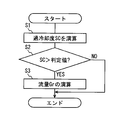
- the degree of supercooling SC is calculated. Specifically, the ECU 15 calculates the degree of supercooling of the refrigerant flowing upstream of the valve body 24 in the second refrigerant passage 22 using the values detected by the second temperature sensor 32a and the second pressure sensor 32b. .
- the degree of supercooling SC is the difference between the saturation temperature (boiling point) of the refrigerant and the temperature of the liquid refrigerant. After calculating the degree of supercooling SC, the flow proceeds to S2.
- the calculated supercooling degree SC is compared with the determination value. If the supercooling degree SC is larger than the determination value, the flow proceeds to S3. When the degree of supercooling SC is not greater than the determination value, for example, when the degree of supercooling SC is equal to or less than the determination value, the flow is terminated.
- the determination value is a value for determining whether or not the refrigerant is in a liquid state. When the degree of supercooling SC is larger than the determination value, it is determined that the refrigerant is in a liquid state. That is, in S3, the flow rate Gr of the refrigerant in the liquid state is calculated. After calculating the flow rate Gr in S3, the flow ends.
- the degree of supercooling SC is outside the predetermined range, in other words, when the degree of supercooling SC is equal to or less than the determination value, the flow rate Gr is not calculated.
- the degree of supercooling when the degree of supercooling (subcool) is small, the refrigerant is in a gas-liquid two-phase state, and the refrigerant density cannot be calculated. Therefore, as shown in FIG. 2, the degree of supercooling is monitored and only the flow rate of the refrigerant in the liquid state is detected.
- the housing 20 is provided with a plurality of sensors 31a, 31b, 32a, 32b, and 33b (hereinafter, these sensors are collectively referred to as the sensor 30). Therefore, the sensors 30 are not provided in the pipe connected to the expansion valve device 10 as in the prior art, but each sensor 30 is provided in the expansion valve device 10 itself, so that the mountability can be improved. Furthermore, since the sensor 30 is provided in the expansion valve device 10, the influence of the outside air temperature can be reduced as compared with the configuration in which the piping is provided. Therefore, the flow rate of the refrigerant can be measured with high accuracy. In other words, since the sensor 30 is mounted inside the expansion valve device 10, an error due to disturbance can be reduced and accuracy can be improved without being affected by the outside air temperature.
- the sensor 30 it is difficult to attach the sensor 30 to the pipe because of work difficulty, detection accuracy, and mountability.
- electromechanical integration it is not necessary to mount the sensor 30 on the pipe in the field work, so that the mountability can be improved.
- the detection accuracy varies due to the difference in the attachment position.
- mounting the sensor 30 at the fixed position of the expansion valve device 10 variations in detection accuracy due to the mounting position can be suppressed, and the detection accuracy can be improved. Further, since there are no special restrictions on the mounting structure, the mounting performance can be improved.
- the expansion valve device 10 can also be integrally provided with wiring. Further, by providing the expansion valve device 10 with the sensor 30 necessary for controlling the refrigeration cycle 11, the wiring of the sensor 30 necessary for controlling the refrigeration cycle 11 can be integrated. Thereby, the structure of the refrigerating cycle 11 can be simplified and manufacturing cost can be reduced.
- the ECU 15 calculates the flow rate Gr of the refrigerant flowing through the second refrigerant flow path 22 and the degree of superheat of the refrigerant flowing through the first refrigerant passage 21 using the values detected by the sensors 30. Therefore, calculations for controlling the refrigeration cycle 11 can be concentrated in the expansion valve device 10. In other words, by centrally disposing the sensors 30 for detecting the flow rate and controlling the superheat degree inside the expansion valve device 10, it is possible to realize low cost and downsizing by reducing the number of attached parts.
- the ECU 15 can control the pressure of the compressor 12. Further, as described above, the ECU 15 also performs superheat degree control. Therefore, the ECU 15 performs both the pressure control and the superheat degree control of the compressor 12, so that the entire refrigeration cycle 11 can be controlled comprehensively. Thereby, the efficiency of the refrigeration cycle 11 can be improved.
- the pressure of the refrigerant on the upstream side and the downstream side of the valve body 24 is detected by the second pressure sensor 32b and the third pressure sensor 33b.
- the second pressure sensor 32 b and the third pressure sensor 33 b are arranged in the same noise environment as the second refrigerant passage 22. Therefore, the detection noise of the second pressure sensor 32b and the third pressure sensor 33b can be canceled by the difference process for obtaining the pressure difference. As a result, the accuracy of detecting the differential pressure is improved, so that the accuracy of detecting the flow rate can be improved.
- the degree of supercooling SC of the refrigerant flowing upstream of the valve body 24 in the second refrigerant passage 22 is calculated, and when the degree of supercooling SC is outside the predetermined range, the flow rate Gr is not calculated or the flow rate is calculated. Gr is calculated, and the calculated flow rate Gr is determined to be an error value (incorrect value).
- the degree of supercooling SC is outside the predetermined range, the flow rate Gr is not calculated or the flow rate is calculated.
- Gr is calculated, and the calculated flow rate Gr is determined to be an error value (incorrect value).
- the second embodiment will be described with reference to FIGS. 3 and 4.
- the present embodiment is different from the first embodiment in that the first pressure sensor 31b is not provided and the third temperature sensor 33a is provided instead of the third pressure sensor 33b.
- the first temperature sensor 31 a is provided in the first refrigerant passage 21.
- a third temperature sensor 33a for detecting the temperature of the refrigerant flowing downstream of the valve body 24 in the second refrigerant passage 22 is provided.
- ECU15 calculates the pressure of the downstream of the valve body 24 of the 2nd refrigerant path 22 from the refrigerant
- the first pressure sensor 31b since the first pressure sensor 31b is not provided, it is necessary to calculate the refrigerant pressure in the first refrigerant passage 21 in order to control the degree of superheat. Therefore, a method of calculating the refrigerant pressure in the first refrigerant passage 21 and controlling the degree of superheat will be described with reference to FIG.
- the upstream and downstream pressure values of the valve body 24 in the second refrigerant passage 22 are known from the second pressure sensor 32b and the third temperature sensor 33a.
- the second pressure sensor 32b detects the pressure value on the upstream side of the valve body 24 in the second refrigerant passage 22, and the pressure value on the downstream side of the valve body 24 in the second refrigerant passage 22 is set to the third temperature.
- the calculation is based on the value detected by the sensor 33a.
- a differential pressure ⁇ P1 that is the difference between the pressure value on the upstream side (inlet) and the pressure value on the downstream side (outlet) of the valve body 24 in the second refrigerant passage 22 is calculated.
- the refrigerant flow rate Gr is calculated from Formula F3 using the differential pressure ⁇ P1 calculated in (a), the refrigerant density ⁇ calculated in (b), and the opening area A. .
- the superheat degree control can be performed based on the outlet pressure Pout of the evaporator 14 obtained as described above. Specifically, as (f) shown in FIG. 4, the pressure Tout is read from the pressure Pout of the first refrigerant passage 21 obtained in (e) to the temperature T. Then, based on the temperature Tout of the first refrigerant passage 21 detected by the first temperature sensor 31a, the degree of superheat SH is calculated using Formula F6. In other words, the temperature Tout of the first refrigerant passage 21 is the temperature of the outlet of the evaporator 14.
- the first pressure sensor 31b for controlling the degree of superheat is not provided in the first refrigerant passage 21, but the refrigerant pressure in the first refrigerant passage 21 is calculated from other detected values and correlations. can do. Thereby, the number of parts can be further reduced as compared with the first embodiment, and the manufacturing cost can be reduced. In other words, it is possible to achieve superheat control and realize highly accurate flow rate detection while realizing cost reduction and downsizing by eliminating the first pressure sensor 31b.
- the refrigeration cycle 11 is applied to a vehicle air conditioner, but is not limited to a vehicle.
- a vehicle air conditioner may be for home use or may be for business use such as a factory or a store.
- the ECU 15 is separate from the expansion valve device 10.
- the ECU 15 for controlling the expansion valve device 10 and the expansion valve device 10 may be integrated.
- a host ECU 15 that controls the entire air conditioner is required.
Landscapes
- Engineering & Computer Science (AREA)
- General Engineering & Computer Science (AREA)
- Mechanical Engineering (AREA)
- Physics & Mathematics (AREA)
- Thermal Sciences (AREA)
- Chemical & Material Sciences (AREA)
- Combustion & Propulsion (AREA)
- Indication Of The Valve Opening Or Closing Status (AREA)
- Temperature-Responsive Valves (AREA)
- Electrically Driven Valve-Operating Means (AREA)
Abstract
膨張弁装置は、ハウジング(20)、弁体(24)、駆動部(27)、第1検出部(31a,31b)、第2検出部(32a,32b)、第3検出部(33a,33b)、および制御部(15)を含んでいる。ハウジングは、第1冷媒通路(21)と第2冷媒通路(22)とが内部に形成されている。弁体は、ハウジング内に設けられ、第2冷媒通路の開度を変更する。第1検出部は、第1冷媒通路を流れる冷媒の温度を検出する。第2検出部は、第2冷媒通路における弁体の上流側を流れる冷媒の温度および圧力を検出する。第3検出部は、第2冷媒通路における弁体の下流側を流れる冷媒の温度または圧力を検出する。制御部は、第2検出部および第3検出部によって検出された値を用いて、第2冷媒通路を流れる冷媒の流量を演算し、第1検出部によって検出された値を用いて、第1冷媒通路を流れる冷媒の過熱度を演算し、過熱度が所定範囲となるように弁体の開度を制御する。
Description
本出願は、当該開示内容が参照によって本出願に組み込まれた、2015年3月11日に出願された日本特許出願2015-048775号を基にしている。
本開示は、冷凍サイクルに設けられ、冷凍サイクルを循環する冷媒を減圧膨張可能な電動の膨張弁装置に関する。
冷凍サイクルを流れる冷媒の流量Gr(kg/s)を算出する方法として、式F1が用いられている。
Gr=C×A×(ΔP/ρ)^0.5 …(F1)
ここで、Cは、流量係数(無次元)であり、Aは、弁の開口面積(m2)であり、ΔPは、膨張弁の上流側と下流側の差圧(Pa)であり、ρは、入口冷媒密度(kg/m3)である。
ここで、Cは、流量係数(無次元)であり、Aは、弁の開口面積(m2)であり、ΔPは、膨張弁の上流側と下流側の差圧(Pa)であり、ρは、入口冷媒密度(kg/m3)である。
この式F1を活用する冷媒流量測定装置として、特許文献1では、膨張弁の上流に圧力と温度センサを搭載し、膨張弁の下流に圧力センサまたは温度センサを搭載した冷媒流量測定装置を開示している。そして各センサの検出値を用いて、膨張弁の上流側と下流側の差圧と冷媒密度を算出する。さらにアクチュエータの弁開度を用いて、式F1に基づき流量を検出している。また凝縮器の出口配管に圧力センサと温度センサを搭載することで、過熱度制御も同時に実現している。
しかしながら、本開示の発明者らによる検討によれば、特許文献1に記載の冷媒流量測定装置では、膨張弁の上流側と下流側の配管に温度センサまたは圧力センサを搭載することで、圧力を推定もしくは直接検出している。しかし、外気温度の影響により過熱度演算および流量検出精度が悪化するおそれがある。
また圧力センサまたは温度センサを複数の配管部位に取り付けるため、搭載性が悪化するとともに、取付部品点数が増加するおそれもある。
さらに膨張弁の上流側と下流側のうちの片側の圧力センサにノイズがのると誤差となり、流量検出精度が悪化するおそれもある。
そこで、本開示は上記点に鑑みてなされたものであり、流量の高精度に測定でき、小型化することができる膨張弁装置を提供することを目的とする。
本開示の膨張弁装置は、冷凍サイクルに設けられ、冷凍サイクルを循環する冷媒を減圧膨張可能である。膨張弁装置は、ハウジング、弁体、駆動部、第1検出部、第2検出部、第3検出部、および制御部を含んでいる。ハウジングは、蒸発器から圧縮機へ流れる冷媒が流通する第1冷媒通路と、凝縮器から蒸発器へ流れる冷媒が流通する第2冷媒通路とが内部に形成されている。弁体は、ハウジング内に設けられ、第2冷媒通路の開度を変更する。駆動部は、弁体を変位させる。第1検出部は、第1冷媒通路を流れる冷媒の温度を検出する。第2検出部は、第2冷媒通路における弁体の上流側を流れる冷媒の温度および圧力を検出する。第3検出部は、第2冷媒通路における弁体の下流側を流れる冷媒の温度または圧力を検出する。制御部は、第1、第2、第3検出部のそれぞれから検出された値を用いて、駆動部を制御して弁体の開度を調節する。制御部は、(i)第2検出部および第3検出部によって検出された値を用いて、第2冷媒通路を流れる冷媒の流量を演算し、(ii)第1検出部によって検出された値を用いて、第1冷媒通路を流れる冷媒の過熱度を演算し、(iii)過熱度が所定範囲となるように弁体の開度を制御する。
本開示によれば、膨張弁装置のハウジングに、各検出部が設けられる。膨張弁装置に接続される配管に各検出部を設ける従来技術と比べて、搭載性を向上することができる。さらに膨張弁装置に検出部を設けるので、検出部を配管に設ける構成に比べて、外気温による影響を小さくすることができる。したがって、冷媒の流量を高精度に測定することができる。
また、制御部は、各検出部によって検出された値を用いて、第2冷媒通路を流れる冷媒の流量と、第1冷媒通路を流れる冷媒の過熱度の双方を演算する。したがって、冷凍サイクルを制御するための演算を、膨張弁装置に集約することができる。
本開示についての上記目的およびその他の目的、特徴や利点は、添付の図面を参照しながら下記の詳細な記述により、より明確になる。
第1実施形態の冷凍サイクルを示す図である。
冷媒の流量の演算処理を示すフローチャートである。
第2実施形態の冷凍サイクルを示す図である。
冷媒のエンタルピーと圧力との関係を示すP‐h線図である。
以下、図面を参照しながら本開示を実施するための形態を、複数の形態について説明する。各実施形態で先行する実施形態で説明している事項に対応している部分には同一の参照符を付すか、または先行の参照符号に一文字追加し、重複する説明を略する場合がある。また各実施形態にて構成の一部を説明している場合、構成の他の部分は、先行して説明している実施形態と同様とする。各実施形態で具体的に説明している部分の組合せばかりではなく、特に組合せに支障が生じなければ、実施形態同士を部分的に組合せることも可能である。
(第1実施形態)
第1実施形態に関して、図1および図2を用いて説明する。膨張弁装置10は、自動車等の空調装置の冷凍サイクル11に使用される減圧装置として機能する電動式の膨張弁装置10である。冷凍サイクル11は、圧縮機12、凝縮器13、膨張弁装置10および蒸発器14を含んで構成され、冷凍サイクル11内を冷媒が循環する。また冷凍サイクル11には、圧縮機12および膨張弁装置10を制御する制御装置(ECU)15が設けられる。
第1実施形態に関して、図1および図2を用いて説明する。膨張弁装置10は、自動車等の空調装置の冷凍サイクル11に使用される減圧装置として機能する電動式の膨張弁装置10である。冷凍サイクル11は、圧縮機12、凝縮器13、膨張弁装置10および蒸発器14を含んで構成され、冷凍サイクル11内を冷媒が循環する。また冷凍サイクル11には、圧縮機12および膨張弁装置10を制御する制御装置(ECU)15が設けられる。
圧縮機12は、内蔵する駆動モータ(図示せず)によって回転駆動される。圧縮機12は、蒸発器14より吸入した冷媒をたとえば臨界圧力以上の高温、高圧となるまで圧縮して吐出する電動式の冷媒圧縮機である。凝縮器13は、圧縮機12より流入する冷媒ガスとの熱交換によって通過する空気に放熱する。
膨張弁装置10は、凝縮器13から流出する冷媒を弁開度に応じて減圧膨張可能な減圧装置で、ECU15によって弁開度が電気的に制御される電動式膨張弁(EVH)が使用されている。
蒸発器14は、膨張弁装置10によって減圧された冷媒を空気との熱交換によって蒸発気化させ、圧縮機12に冷媒ガスを供給する。
ECU15は、制御処理や演算処理を行うCPU、各種プログラムやデータを保存するROM、RAMなどのメモリ、I/Oポートなどの機能を含んで構成され、それ自体は周知の構造を持つマイクロコンピュータを内蔵している。そして、ECU15は、電力供給されると、接続される装置からの操作信号、各種センサからのセンサ信号、およびメモリ内に格納された制御プログラムに基づいて、空調装置の各アクチュエータを電気的に制御する。
次に、膨張弁装置10に関して説明する。図1に示すように、膨張弁装置10は角柱状のハウジング20を有する。ハウジング20は、金属製、たとえばアルミニウム製である。ハウジング20には、蒸発器14から圧縮機12へ流れる冷媒が流通する第1冷媒通路21と、凝縮器13から蒸発器14へ流れる冷媒が流通する第2冷媒通路22とが内部に形成されている。具体的には、ハウジング20には、蒸発器14の出口から圧縮機12の入口へと向かう部分に介在される低圧の気相冷媒(低圧冷媒)が通過する第1冷媒通路21が形成されている。またハウジング20には、凝縮器13の出口から蒸発器14の冷媒入口へと向かう部分に介在される液相冷媒が通過する第2冷媒通路22が形成されている。第1冷媒通路21と第2冷媒通路22は、図1の上下方向に互いに離れて、図1の左右方向に延びるように形成されている。
第2冷媒通路22には、凝縮器13から供給された液体冷媒を断熱膨張させるためのオリフィス部23が形成されている。オリフィス部23は、第2冷媒通路22において断面積の小さい狭い通路であり、弁部材26の軸方向に沿うように設けられている。オリフィス部23の入口には弁座25が形成されていて、弁座25には弁部材26により支持された弁体24が着座または離座する。これによって弁体24は、第2冷媒通路22の開度を変更する。具体的には、弁体24と弁座25との距離を調整することにより、オリフィス部23を流通する冷媒の量が調節される。
弁体24と弁部材26とは溶接などによって、一体となるように固定されている。弁部材26は、長手状の部材であり、上方の端部が駆動部27に連結されており、下方の端部に弁体24が設けられる。
第2冷媒通路22は、凝縮器13の液冷媒が導入される第2冷媒流入口22aから第2冷媒流出口22bに至るまでの通路であり、その途中に第2冷媒流入口22aに連通する弁室28が設けられている。弁室28は、オリフィス部23の中心線と同軸に形成される室である。
さらに、ハウジング20には、上下方向に延びる孔部29がオリフィス部23の中心軸線と同軸でその延長線上に第1冷媒通路21に連通するように形成されている。孔部29には、弁部材26が貫通するように配置されている。
ハウジング20の上端には、駆動部27が設けられている。駆動部27は、電動によって、弁体24を変位させる。駆動部27は、ECU15によって制御される。駆動部27は、ステッパーモータなどのモータ(図示せず)と、モータの回転力を上下方向にスライド変位させる変換部(図示せず)とを備える。変換部は、外周面に雄ねじ部が形成された円筒形状の雄ねじ部材を有する。モータのロータの本体部は、雌ねじ部が形成されている。この雌ねじ部と雄ねじ部とは螺合しており、ロータが回転するとロータが軸線方向(図1の上下方向)に変位するようになっている。ロータが回転して軸線方向に変位すると、ロータの本体部に係止している弁部材26も共に変位し、弁体24と弁座25と間の開度を変更可能になっている。
次に、第1冷媒通路21および第2冷媒通路22に設けられるセンサに関して説明する。本実施形態では、第1検出部として、第1温度センサ31aおよび第1圧力センサ31bが第1冷媒通路21内に設けられている。第1温度センサ31aは、第1冷媒通路21を流れる冷媒の温度を検出する。第1圧力センサ31bは、第1冷媒通路21を流れる冷媒の圧力を検出する。
第2冷媒通路22における弁体24の上流側を流れる冷媒の温度および圧力を検出する第2検出部として、第2温度センサ32aおよび第2圧力センサ32bが設けられている。第2冷媒通路22における弁体24の上流側は、弁体24の冷媒の流れ方向の上流側であり、凝縮器13側である。第2冷媒通路22における弁体24の下流側を流れる冷媒の圧力を検出する第3圧力センサ33bが設けられている。第2冷媒通路22における弁体24の下流側は、弁体24の冷媒の流れ方向の下流側であり、蒸発器14側である。
第1冷媒通路21および第2冷媒通路22に設けられるこれらのセンサは、ECU15に検出した情報を出力する。ECU15は、制御部であって、第2圧力センサ32b、第2温度センサ32aおよび第3圧力センサ33bによって検出された値を用いて、第2冷媒通路22を流れる冷媒の流量Gr(kg/s)を演算する。具体的には、以下の式F2を用いて流量Gr(kg/s)を演算する。
Gr=C×A×(ΔP1/ρ)^0.5 …(F2)
前述のように、Cは、流量係数(無次元)であり、Aは、弁体24の開口面積(m2)であり、ΔP1は、弁体24の上流側と下流側(前後)の差圧(Pa)であり、ρは、冷媒密度(kg/m3)である。流量係数Cは、既知の値である。また開口面積Aは、膨張弁装置10の弁開度によって決まる既知の値である。差圧ΔP1は、第2圧力センサ32bおよび第3圧力センサ33bの差によって算出することができる。冷媒密度ρは、第2圧力センサ32bおよび第2温度センサ32aによって検出された冷媒の圧力と温度とから求めることができる。したがって前述のように、式F2を用いることによって、冷媒の流量Grを演算することができる。
前述のように、Cは、流量係数(無次元)であり、Aは、弁体24の開口面積(m2)であり、ΔP1は、弁体24の上流側と下流側(前後)の差圧(Pa)であり、ρは、冷媒密度(kg/m3)である。流量係数Cは、既知の値である。また開口面積Aは、膨張弁装置10の弁開度によって決まる既知の値である。差圧ΔP1は、第2圧力センサ32bおよび第3圧力センサ33bの差によって算出することができる。冷媒密度ρは、第2圧力センサ32bおよび第2温度センサ32aによって検出された冷媒の圧力と温度とから求めることができる。したがって前述のように、式F2を用いることによって、冷媒の流量Grを演算することができる。
またECU15は、第1温度センサ31aおよび第1圧力センサ31bによって検出された値を用いて、第1冷媒通路21を流れる冷媒の過熱度を演算する。過熱度は、特定の圧力下で冷媒蒸気が飽和温度から何度高いかを数字で表わしたものである。したがって過熱度を演算するためには、まず第1圧力センサ31bで圧力を測定し、飽和圧力を圧力温度表で温度に読み替える。次に、第1圧力センサ31bと同じ場所の温度を第1温度センサ31aによって検出し、読み替えた温度との差を求める。この差が過熱度となる。
過熱度によって、蒸発器14へ流入する冷媒量が適切かどうかが判断できる。たとえば過熱度が非常に高い状態では、十分な冷媒が供給されておらず、効率的な冷却が行われず、エネルギー効率が悪くなる。逆に過熱度が異常に低い状態では、過剰な冷媒が供給されており、液バックの可能性が発生し、圧縮機12の損傷を引き起こされるおそれがある。そこでECU15は、過熱度が所定範囲となるように弁体24の開度を制御する。これによって、冷媒の蒸発状態が適度な過熱度となるような冷媒圧力になるように減圧される。
次に、過冷却度に関する処理について、図2を用いて説明する。図2に示す処理は、過冷却度を監視するために、ECU15によって短時間に繰り返し実行される。S1では、過冷却度SCを演算する。具体的には、ECU15が、第2温度センサ32aおよび第2圧力センサ32bによって検出された値を用いて、第2冷媒通路22における弁体24の上流側を流れる冷媒の過冷却度を演算する。過冷却度SCとは、冷媒の飽和温度(沸点)と液冷媒の温度との差である。過冷却度SCを演算した後、フローはS2に進む。
S2では、演算した過冷却度SCと判定値とを比較し、過冷却度SCが判定値よりも大きい場合には、フローはS3に進む。過冷却度SCが判定値よりも大きくない場合、例えば、過冷却度SCが判定値以下の場合には、フローを終了する。判定値は、冷媒が液状態であるか否かを判定する値である。過冷却度SCが判定値よりも大きい場合、冷媒は液状態であると判断される。つまり、S3では、液状態の冷媒の流量Grを演算する。S3において流量Grを演算した後、フローを終了する。
このように過冷却度SCが所定範囲外の場合、換言すれば、過冷却度SCが判定値以下の場合は、流量Grを演算しない。これは流量測定において、過冷却度(サブクール)が小さい場合、冷媒は気液2相状態となり、冷媒密度を算出することができないからである。そこで図2に示すように、過冷却度を監視し、液状態の冷媒の流量のみを検出する。本実施形態では、S2において過冷却度SCが所定値よりも大きいと判断された場合は(S2:YES)、S3において流量Grを演算した後にフローを終了し、S2において過冷却度SCが所定値以下であると判断された場合は(S3:NO)、S3の処理をスキップしてフローを終了している。しかしながら、S2においてNOと判定された場合にも流量Grを演算し、演算した流量Grをエラー値(正しくない値)であると判定する処理を設けても良い。
以上説明したように本実施形態の膨張弁装置10では、ハウジング20に複数のセンサ31a,31b,32a,32b,33b(以下、これら複数のセンサをセンサ30と総称する)が設けられる。したがって従来技術のように膨張弁装置10に接続される配管にセンサ30を設けるのではなく、膨張弁装置10自体に各センサ30が設けられるので、搭載性を向上することができる。さらに膨張弁装置10にセンサ30を設けるので、外気温による影響を配管に設ける構成に比べて小さくすることができる。したがって冷媒の流量を高精度に測定することができる。換言すると、膨張弁装置10の内部にセンサ30が搭載されるため、外気温影響を受けることなく、外乱による誤差低減し、精度向上することができる。
また配管にセンサ30を取り付けることは、作業困難性、検出精度および取付性から困難である。しかし、予め、各種のセンサ30を膨張弁装置10に一体にして、いわゆる機電一体とすることによって、現場作業にてセンサ30を配管に搭載する必要がないので搭載性を向上することができる。またセンサ30を配管に取付ける場合、取付け位置の違いにより検出精度のばらつきが生じる。これに対し、膨張弁装置10の固定位置にセンサ30を搭載することによって取付け位置による検出精度のばらつきを抑制し、検出精度も向上することができる。また取付構造に特別な制約がなくなるので、搭載性能を向上することができる。
また、配管にセンサ30を取り付ける場合、検出した値を送信する配線が必要である。この配線の取り回しが難しい場合がある。しかし、本実施形態では、膨張弁装置10に配線も一体に設けることができる。また冷凍サイクル11の制御に必要なセンサ30を膨張弁装置10に設けることによって、冷凍サイクル11の制御に必要なセンサ30の配線を集約することができる。これによって、冷凍サイクル11の構成を簡素化でき、製造コストを低減することができる。
またECU15は、各センサ30によって検出された値を用いて、第2冷媒流路22を流れる冷媒の流量Grと第1冷媒通路21を流れる冷媒の過熱度を演算する。したがって、冷凍サイクル11を制御するための演算を、膨張弁装置10に集約することができる。換言すると、膨張弁装置10の内部に流量検出と過熱度制御用のセンサ30を集約配置することで、取付け部品削減による低コストおよび小型化を実現することができる。
また本実施形態では、第2冷媒通路22に第2圧力センサ32bが設けられるので、圧縮機12の圧力制御をECU15が行うことができる。さらに、前述のように、ECU15は、過熱度制御も実施する。したがってECU15は、圧縮機12の圧力制御と過熱度制御の両方を実施するので、統括的に冷凍サイクル11の全体を制御することができる。これによって冷凍サイクル11の効率を向上することができる。
また本実施形態では、第2冷媒通路22では、弁体24の上流側および下流側における冷媒の圧力を、第2圧力センサ32bおよび第3圧力センサ33bによって検出する。これによって、第2圧力センサ32bと第3圧力センサ33bとが第2冷媒通路22という同じノイズ環境に配置されることになる。したがって、圧力差を求める差分処理で、第2圧力センサ32bと第3圧力センサ33bの検出ノイズをキャンセルすることができる。その結果、差圧の検出精度が向上するので、流量検出精度を向上することができる。
さらに本実施形態では、第2冷媒通路22における弁体24の上流側を流れる冷媒の過冷却度SCを演算し、過冷却度SCが所定範囲外の場合、流量Grを演算しないか、または流量Grを演算して、演算した流量Grをエラー値(正しくない値)であると判定する。このように、過冷却度SCによって冷媒が液状態であるか否かを判定し、冷媒検出判定を実施することで、流量誤検出を回避することができる。
(第2実施形態)
第2実施形態に関して、図3および図4を用いて説明する。本実施形態では、第1実施形態に比べて、第1圧力センサ31bを備えず、第3圧力センサ33bに換えて第3温度センサ33aを備える点が異なっている。つまり。第1冷媒通路21には、第1温度センサ31aだけが設けられている。また第3圧力センサ33bに換えて、第2冷媒通路22における弁体24の下流側を流れる冷媒の温度を検出する第3温度センサ33aが設けられている。
第2実施形態に関して、図3および図4を用いて説明する。本実施形態では、第1実施形態に比べて、第1圧力センサ31bを備えず、第3圧力センサ33bに換えて第3温度センサ33aを備える点が異なっている。つまり。第1冷媒通路21には、第1温度センサ31aだけが設けられている。また第3圧力センサ33bに換えて、第2冷媒通路22における弁体24の下流側を流れる冷媒の温度を検出する第3温度センサ33aが設けられている。
ECU15は、第3温度センサ33aが検出した値を用いて、気液2相状態の冷媒飽和温度より第2冷媒通路22の弁体24の下流側の圧力を演算する。したがって第3圧力センサ33bが搭載されていなくても、第3温度センサ33aが搭載されていれば、圧力を得ることができる。したがって、本実施形態では第3検出部として第3温度センサ33aが用いられているが、第3温度センサ33aに換えて第3圧力センサ33bを用いてもよい。
また本実施形態では、第1圧力センサ31bを備えないので、過熱度の制御のためには、第1冷媒通路21の冷媒圧力を算出する必要がある。そこで図4を用いて、第1冷媒通路21の冷媒圧力を演算し、過熱度の制御を実施する方法に関して説明する。
まず、第2冷媒通路22における弁体24の上流側と下流側の圧力値は、第2圧力センサ32bおよび第3温度センサ33aより既知である。具体的には、第2冷媒通路22における弁体24の上流側の圧力値を第2圧力センサ32bが検出し、第2冷媒通路22における弁体24の下流側の圧力値を、第3温度センサ33aによって検出された値に基づいて演算されている。図4に示す(a)では、第2冷媒通路22における弁体24の上流側(入口)の圧力値と下流側(出口)の圧力値の差である差圧ΔP1を算出する。
次に、図4で示す(b)のように、第2冷媒通路22のうち弁体24の上流側のほぼ同位置に配置される第2圧力センサ32bおよび第2温度センサ32aによって検出された値を用いて、冷媒密度ρを算出する。
次に、図4で示す(c)では、(a)で算出した差圧ΔP1、(b)で算出した冷媒密度ρ、および開口面積Aを用いて、式F3から冷媒の流量Grを算出する。
Gr=C×A×(2×ΔP1/ρ)^0.5 …(F3)
次に、図4で示す(d)で、(c)で算出した流量Grと蒸発器14での圧力損失ΔP2の相関関係である式F4を用いて、蒸発器14の圧力損失ΔP2を算出する。換言すると、流量Grがわかれば、蒸発器14での圧力損失ΔP2を、式F4を用いて算出することができる。
次に、図4で示す(d)で、(c)で算出した流量Grと蒸発器14での圧力損失ΔP2の相関関係である式F4を用いて、蒸発器14の圧力損失ΔP2を算出する。換言すると、流量Grがわかれば、蒸発器14での圧力損失ΔP2を、式F4を用いて算出することができる。
ΔP2=f(Gr) …(F4)
次に、図4で示す(e)では、第2冷媒通路22における弁体24の下流の第2冷媒流出口22bにおける圧力Pinから、(d)で求めた圧力損失ΔP2を減算することで、蒸発器14の出口の圧力Poutを算出することができる。
次に、図4で示す(e)では、第2冷媒通路22における弁体24の下流の第2冷媒流出口22bにおける圧力Pinから、(d)で求めた圧力損失ΔP2を減算することで、蒸発器14の出口の圧力Poutを算出することができる。
Pout=Pin-ΔP2 …(F5)
式F5で算出される蒸発器14の出口の圧力Poutは、第1冷媒通路21の圧力である。したがって第1圧力センサ31bを用いずとも、第1冷媒通路21の圧力を算出することができる。
式F5で算出される蒸発器14の出口の圧力Poutは、第1冷媒通路21の圧力である。したがって第1圧力センサ31bを用いずとも、第1冷媒通路21の圧力を算出することができる。
上述のように求めた蒸発器14の出口の圧力Poutに基づいて、過熱度制御を実施することができる。具体的には、図4で示す(f)のように、(e)で求めた第1冷媒通路21の圧力Poutから圧力温度表で温度Tに読み替える。そして、第1温度センサ31aによって検出された第1冷媒通路21の温度Toutをもとに式F6を用いて過熱度SHを算出する。第1冷媒通路21の温度Toutは、換言すれば、蒸発器14の出口の温度である。
SH=Tout-T…(F6)
このように本実施形態では、第1冷媒通路21に過熱度制御用の第1圧力センサ31bが設けられていないが、他の検出値および相関関係から、第1冷媒通路21における冷媒圧力を算出することができる。これによって、第1実施形態よりも部品点数をさらに削減して、製造コストを低減することができる。換言すると、第1圧力センサ31bの廃止によるコスト低減および小型化を実現しつつ、過熱度制御を成立させ、かつ高精度な流量検出を実現することができる。
このように本実施形態では、第1冷媒通路21に過熱度制御用の第1圧力センサ31bが設けられていないが、他の検出値および相関関係から、第1冷媒通路21における冷媒圧力を算出することができる。これによって、第1実施形態よりも部品点数をさらに削減して、製造コストを低減することができる。換言すると、第1圧力センサ31bの廃止によるコスト低減および小型化を実現しつつ、過熱度制御を成立させ、かつ高精度な流量検出を実現することができる。
(その他の実施形態)
以上、本開示の好ましい実施形態について説明したが、本開示は上述した実施形態に何ら制限されることなく、本開示の主旨を逸脱しない範囲において種々変形して実施することが可能である。
以上、本開示の好ましい実施形態について説明したが、本開示は上述した実施形態に何ら制限されることなく、本開示の主旨を逸脱しない範囲において種々変形して実施することが可能である。
上記実施形態の構造は、あくまで例示であって、本開示の範囲はこれらの記載の範囲に限定されるものではない。本開示の範囲は、本開示の記載と均等の意味及び範囲内での全ての変更を含むものである。
前述の第1実施形態では、冷凍サイクル11は車両用の空調装置に適用されているが、車両用に限るものではない。たとえば家庭用であってもよく、工場および店舗などの業務用であってもよい。
前述の第1実施形態では、ECU15は、膨張弁装置10と別体であるが、膨張弁装置10を制御するためのECU15と膨張弁装置10とが一体であってもよい。ECU15と膨張弁装置10と一体の場合は、空調装置の全体を制御する上位のECU15が必要となる。
Claims (5)
- 冷凍サイクル(11)に設けられ、前記冷凍サイクルを循環する冷媒を減圧膨張可能な膨張弁装置であって、
蒸発器(14)から圧縮機(12)へ流れる冷媒が流通する第1冷媒通路(21)と、凝縮器(13)から前記蒸発器へ流れる冷媒が流通する第2冷媒通路(22)とが内部に形成されたハウジング(20)と、
前記ハウジング内に設けられ、前記第2冷媒通路の開度を変更する弁体(24)と、
前記弁体を変位させる駆動部(27)と、
前記第1冷媒通路を流れる冷媒の温度を検出する第1検出部(31a,31b)と、
前記第2冷媒通路における前記弁体の上流側を流れる冷媒の温度および圧力を検出する第2検出部(32a,32b)と、
前記第2冷媒通路における前記弁体の下流側を流れる冷媒の温度または圧力を検出する第3検出部(33a,33b)と、
前記第1、第2、第3検出部のそれぞれから検出された値を用いて、前記駆動部を制御して前記弁体の開度を調節する制御部(15)と、を含み、
前記制御部は、
前記第2検出部および前記第3検出部によって検出された値を用いて、前記第2冷媒通路を流れる冷媒の流量を演算し、
前記第1検出部によって検出された値を用いて、前記第1冷媒通路を流れる冷媒の過熱度を演算し、
前記過熱度が所定範囲となるように前記弁体の開度を制御する膨張弁装置。 - 前記第3検出部は、前記第2冷媒通路における前記弁体の下流側を流れる冷媒の圧力を検出する請求項1に記載の膨張弁装置。
- 前記制御部は、演算した前記流量、および前記第3検出部によって検出された値を用いて、前記第1冷媒通路を流れる冷媒の圧力を演算する請求項1または2に記載の膨張弁装置。
- 前記制御部は、
前記第2検出部によって検出された値を用いて、前記第2冷媒通路における前記弁体の上流側を流れる冷媒の過冷却度を演算し、
前記過冷却度が所定範囲外の場合、前記流量を演算しないか、または前記流量を演算して、演算した前記流量をエラー値であると判定する請求項1ないし3のいずれか1つに記載の膨張弁装置。 - 前記第1検出部は、前記第1冷媒通路を流れる冷媒の圧力を検出可能であり、
前記過熱度は、前記第1検出部によって検出された温度及び圧力の値を用いて演算される請求項1に記載の膨張弁装置。
Priority Applications (3)
| Application Number | Priority Date | Filing Date | Title |
|---|---|---|---|
| CN201680010241.1A CN107250690B (zh) | 2015-03-11 | 2016-03-10 | 膨胀阀装置 |
| DE112016001128.8T DE112016001128T5 (de) | 2015-03-11 | 2016-03-10 | Expansionsventilvorrichtung |
| US15/549,936 US20180023835A1 (en) | 2015-03-11 | 2016-03-10 | Expansion valve device |
Applications Claiming Priority (2)
| Application Number | Priority Date | Filing Date | Title |
|---|---|---|---|
| JP2015-048775 | 2015-03-11 | ||
| JP2015048775A JP2016169893A (ja) | 2015-03-11 | 2015-03-11 | 膨張弁装置 |
Publications (1)
| Publication Number | Publication Date |
|---|---|
| WO2016143347A1 true WO2016143347A1 (ja) | 2016-09-15 |
Family
ID=56880268
Family Applications (1)
| Application Number | Title | Priority Date | Filing Date |
|---|---|---|---|
| PCT/JP2016/001320 Ceased WO2016143347A1 (ja) | 2015-03-11 | 2016-03-10 | 膨張弁装置 |
Country Status (5)
| Country | Link |
|---|---|
| US (1) | US20180023835A1 (ja) |
| JP (1) | JP2016169893A (ja) |
| CN (1) | CN107250690B (ja) |
| DE (1) | DE112016001128T5 (ja) |
| WO (1) | WO2016143347A1 (ja) |
Families Citing this family (11)
| Publication number | Priority date | Publication date | Assignee | Title |
|---|---|---|---|---|
| US11060771B2 (en) * | 2016-10-25 | 2021-07-13 | Samsung Electronics Co., Ltd. | Air conditioner with a refrigerant ratio adjustor |
| JP7049367B2 (ja) * | 2017-05-09 | 2022-04-06 | ジャージャン サンフア オートモーティヴ コンポーネンツ カンパニー リミテッド | 電子膨張弁、熱管理ユニット、冷却システム及び電子膨張弁の製造方法 |
| KR102354891B1 (ko) * | 2017-05-31 | 2022-01-25 | 삼성전자주식회사 | 공기 조화기 및 그 제어 방법 |
| JP2019093988A (ja) * | 2017-11-27 | 2019-06-20 | 本田技研工業株式会社 | 車両用空調装置 |
| JP7176310B2 (ja) * | 2018-09-11 | 2022-11-22 | 富士電機株式会社 | ヒートポンプ式蒸気生成装置 |
| JP2020076516A (ja) * | 2018-11-06 | 2020-05-21 | 富士電機株式会社 | ヒートポンプサイクルおよびヒートポンプ式蒸気生成装置 |
| US11674726B2 (en) * | 2020-06-30 | 2023-06-13 | Thermo King Llc | Systems and methods for transport climate control circuit management and isolation |
| US11754204B2 (en) | 2020-07-27 | 2023-09-12 | Hanon Systems | Stabilized h-plate |
| CN115342539A (zh) * | 2021-05-14 | 2022-11-15 | 浙江三花汽车零部件有限公司 | 制冷系统、膨胀阀组件以及制冷系统控制方法 |
| JP7835445B2 (ja) * | 2023-09-22 | 2026-03-25 | 株式会社不二工機 | 電動弁 |
| JP7820857B2 (ja) * | 2024-03-22 | 2026-02-26 | 株式会社不二工機 | 電動弁 |
Citations (6)
| Publication number | Priority date | Publication date | Assignee | Title |
|---|---|---|---|---|
| JPS6115057A (ja) * | 1984-07-02 | 1986-01-23 | 株式会社日立製作所 | 冷凍サイクルの冷媒流量測定装置 |
| US6375086B1 (en) * | 2001-07-30 | 2002-04-23 | Eaton Corporation | Modulating refrigerant flow through a motorized expansion valve |
| WO2005008132A2 (en) * | 2003-07-09 | 2005-01-27 | Emerson Electric Co. | Sensing and control of valve flow rate |
| JP2005315550A (ja) * | 2004-04-29 | 2005-11-10 | Ysd:Kk | 冷媒流量制御装置 |
| US20100031681A1 (en) * | 2006-03-31 | 2010-02-11 | Parker-Hannifin Corporation | Electronic block valve |
| JP2010031998A (ja) * | 2008-07-30 | 2010-02-12 | Denso Corp | 膨張弁 |
Family Cites Families (3)
| Publication number | Priority date | Publication date | Assignee | Title |
|---|---|---|---|---|
| US7784296B2 (en) * | 2007-03-08 | 2010-08-31 | Nordyne Inc. | System and method for controlling an air conditioner or heat pump |
| JP2011033235A (ja) * | 2009-07-30 | 2011-02-17 | Sanden Corp | 冷凍サイクル |
| WO2013144994A1 (ja) * | 2012-03-27 | 2013-10-03 | 三菱電機株式会社 | 空気調和装置 |
-
2015
- 2015-03-11 JP JP2015048775A patent/JP2016169893A/ja active Pending
-
2016
- 2016-03-10 DE DE112016001128.8T patent/DE112016001128T5/de not_active Withdrawn
- 2016-03-10 CN CN201680010241.1A patent/CN107250690B/zh not_active Expired - Fee Related
- 2016-03-10 WO PCT/JP2016/001320 patent/WO2016143347A1/ja not_active Ceased
- 2016-03-10 US US15/549,936 patent/US20180023835A1/en not_active Abandoned
Patent Citations (6)
| Publication number | Priority date | Publication date | Assignee | Title |
|---|---|---|---|---|
| JPS6115057A (ja) * | 1984-07-02 | 1986-01-23 | 株式会社日立製作所 | 冷凍サイクルの冷媒流量測定装置 |
| US6375086B1 (en) * | 2001-07-30 | 2002-04-23 | Eaton Corporation | Modulating refrigerant flow through a motorized expansion valve |
| WO2005008132A2 (en) * | 2003-07-09 | 2005-01-27 | Emerson Electric Co. | Sensing and control of valve flow rate |
| JP2005315550A (ja) * | 2004-04-29 | 2005-11-10 | Ysd:Kk | 冷媒流量制御装置 |
| US20100031681A1 (en) * | 2006-03-31 | 2010-02-11 | Parker-Hannifin Corporation | Electronic block valve |
| JP2010031998A (ja) * | 2008-07-30 | 2010-02-12 | Denso Corp | 膨張弁 |
Also Published As
| Publication number | Publication date |
|---|---|
| US20180023835A1 (en) | 2018-01-25 |
| CN107250690A (zh) | 2017-10-13 |
| JP2016169893A (ja) | 2016-09-23 |
| CN107250690B (zh) | 2020-09-04 |
| DE112016001128T5 (de) | 2017-11-30 |
Similar Documents
| Publication | Publication Date | Title |
|---|---|---|
| CN107250690B (zh) | 膨胀阀装置 | |
| US9797640B2 (en) | Refrigerating apparatus and corresponding control device | |
| EP2729743B1 (en) | A method for controlling operation of a vapour compression system in a subcritical and a supercritical mode | |
| US20210025630A1 (en) | Compressor protection and control in hvac systems | |
| JP4408413B2 (ja) | 冷凍装置及びこれを用いた空気調和機 | |
| JP6289403B2 (ja) | 冷媒不足判定装置、これを備えた冷凍サイクル、及び冷凍サイクルの冷媒不足判定方法 | |
| CN101784850A (zh) | 制冷监控系统和方法 | |
| US8978484B2 (en) | Drive torque estimation device for compressor and condenser used for the device | |
| US11162726B2 (en) | Liquid detection system | |
| US20120125025A1 (en) | Refrigeration Cycle | |
| JP4715797B2 (ja) | エジェクタ式冷凍サイクル | |
| CN105202838B (zh) | 多联机系统及其中间压力控制方法 | |
| WO2011013541A1 (ja) | 車両用空調装置 | |
| JP6485256B2 (ja) | 冷凍サイクル装置 | |
| JP6105972B2 (ja) | ターボ冷凍機 | |
| JP2005106380A (ja) | 冷凍サイクル装置 | |
| KR102797367B1 (ko) | 차량용 압축기의 구동 토크 예측 장치 및 그 방법 | |
| JP7760609B2 (ja) | 冷凍システム、膨張弁アセンブリ及び冷凍システム制御方法 | |
| CN112955702A (zh) | 用于制冷剂组成物查验的诊断 | |
| JP2006001505A (ja) | 車両用空調装置 | |
| US12486993B2 (en) | HVAC system with leak detection and method of use | |
| JP4840007B2 (ja) | 冷凍空調装置の制御装置 | |
| CN113348328A (zh) | 空调机 | |
| KR20090065363A (ko) | 자동차용 에어컨 제어장치 | |
| JP2004184073A (ja) | 冷媒の物理量を測定する手段を収容しうる要素を少なくとも1つ具備する自動車用空調装置の冷凍サイクル |
Legal Events
| Date | Code | Title | Description |
|---|---|---|---|
| 121 | Ep: the epo has been informed by wipo that ep was designated in this application |
Ref document number: 16761320 Country of ref document: EP Kind code of ref document: A1 |
|
| WWE | Wipo information: entry into national phase |
Ref document number: 15549936 Country of ref document: US |
|
| WWE | Wipo information: entry into national phase |
Ref document number: 112016001128 Country of ref document: DE |
|
| 122 | Ep: pct application non-entry in european phase |
Ref document number: 16761320 Country of ref document: EP Kind code of ref document: A1 |