WO2016143287A1 - 密閉型電池 - Google Patents
密閉型電池 Download PDFInfo
- Publication number
- WO2016143287A1 WO2016143287A1 PCT/JP2016/001046 JP2016001046W WO2016143287A1 WO 2016143287 A1 WO2016143287 A1 WO 2016143287A1 JP 2016001046 W JP2016001046 W JP 2016001046W WO 2016143287 A1 WO2016143287 A1 WO 2016143287A1
- Authority
- WO
- WIPO (PCT)
- Prior art keywords
- valve body
- terminal plate
- thin
- sealed battery
- welded
- Prior art date
- Legal status (The legal status is an assumption and is not a legal conclusion. Google has not performed a legal analysis and makes no representation as to the accuracy of the status listed.)
- Ceased
Links
Images


Classifications
-
- H—ELECTRICITY
- H01—ELECTRIC ELEMENTS
- H01M—PROCESSES OR MEANS, e.g. BATTERIES, FOR THE DIRECT CONVERSION OF CHEMICAL ENERGY INTO ELECTRICAL ENERGY
- H01M50/00—Constructional details or processes of manufacture of the non-active parts of electrochemical cells other than fuel cells, e.g. hybrid cells
- H01M50/50—Current conducting connections for cells or batteries
- H01M50/543—Terminals
- H01M50/552—Terminals characterised by their shape
- H01M50/559—Terminals adapted for cells having curved cross-section, e.g. round, elliptic or button cells
- H01M50/56—Cup shaped terminals
-
- H—ELECTRICITY
- H01—ELECTRIC ELEMENTS
- H01M—PROCESSES OR MEANS, e.g. BATTERIES, FOR THE DIRECT CONVERSION OF CHEMICAL ENERGY INTO ELECTRICAL ENERGY
- H01M50/00—Constructional details or processes of manufacture of the non-active parts of electrochemical cells other than fuel cells, e.g. hybrid cells
- H01M50/10—Primary casings; Jackets or wrappings
- H01M50/147—Lids or covers
- H01M50/166—Lids or covers characterised by the methods of assembling casings with lids
- H01M50/167—Lids or covers characterised by the methods of assembling casings with lids by crimping
-
- H—ELECTRICITY
- H01—ELECTRIC ELEMENTS
- H01M—PROCESSES OR MEANS, e.g. BATTERIES, FOR THE DIRECT CONVERSION OF CHEMICAL ENERGY INTO ELECTRICAL ENERGY
- H01M50/00—Constructional details or processes of manufacture of the non-active parts of electrochemical cells other than fuel cells, e.g. hybrid cells
- H01M50/10—Primary casings; Jackets or wrappings
- H01M50/147—Lids or covers
- H01M50/166—Lids or covers characterised by the methods of assembling casings with lids
- H01M50/171—Lids or covers characterised by the methods of assembling casings with lids using adhesives or sealing agents
-
- H—ELECTRICITY
- H01—ELECTRIC ELEMENTS
- H01M—PROCESSES OR MEANS, e.g. BATTERIES, FOR THE DIRECT CONVERSION OF CHEMICAL ENERGY INTO ELECTRICAL ENERGY
- H01M50/00—Constructional details or processes of manufacture of the non-active parts of electrochemical cells other than fuel cells, e.g. hybrid cells
- H01M50/10—Primary casings; Jackets or wrappings
- H01M50/183—Sealing members
- H01M50/184—Sealing members characterised by their shape or structure
-
- H—ELECTRICITY
- H01—ELECTRIC ELEMENTS
- H01M—PROCESSES OR MEANS, e.g. BATTERIES, FOR THE DIRECT CONVERSION OF CHEMICAL ENERGY INTO ELECTRICAL ENERGY
- H01M50/00—Constructional details or processes of manufacture of the non-active parts of electrochemical cells other than fuel cells, e.g. hybrid cells
- H01M50/10—Primary casings; Jackets or wrappings
- H01M50/183—Sealing members
- H01M50/186—Sealing members characterised by the disposition of the sealing members
- H01M50/188—Sealing members characterised by the disposition of the sealing members the sealing members being arranged between the lid and terminal
-
- H—ELECTRICITY
- H01—ELECTRIC ELEMENTS
- H01M—PROCESSES OR MEANS, e.g. BATTERIES, FOR THE DIRECT CONVERSION OF CHEMICAL ENERGY INTO ELECTRICAL ENERGY
- H01M50/00—Constructional details or processes of manufacture of the non-active parts of electrochemical cells other than fuel cells, e.g. hybrid cells
- H01M50/30—Arrangements for facilitating escape of gases
- H01M50/342—Non-re-sealable arrangements
- H01M50/3425—Non-re-sealable arrangements in the form of rupturable membranes or weakened parts, e.g. pierced with the aid of a sharp member
-
- H—ELECTRICITY
- H01—ELECTRIC ELEMENTS
- H01M—PROCESSES OR MEANS, e.g. BATTERIES, FOR THE DIRECT CONVERSION OF CHEMICAL ENERGY INTO ELECTRICAL ENERGY
- H01M50/00—Constructional details or processes of manufacture of the non-active parts of electrochemical cells other than fuel cells, e.g. hybrid cells
- H01M50/50—Current conducting connections for cells or batteries
- H01M50/543—Terminals
- H01M50/552—Terminals characterised by their shape
- H01M50/559—Terminals adapted for cells having curved cross-section, e.g. round, elliptic or button cells
-
- H—ELECTRICITY
- H01—ELECTRIC ELEMENTS
- H01M—PROCESSES OR MEANS, e.g. BATTERIES, FOR THE DIRECT CONVERSION OF CHEMICAL ENERGY INTO ELECTRICAL ENERGY
- H01M50/00—Constructional details or processes of manufacture of the non-active parts of electrochemical cells other than fuel cells, e.g. hybrid cells
- H01M50/50—Current conducting connections for cells or batteries
- H01M50/543—Terminals
- H01M50/562—Terminals characterised by the material
-
- H—ELECTRICITY
- H01—ELECTRIC ELEMENTS
- H01M—PROCESSES OR MEANS, e.g. BATTERIES, FOR THE DIRECT CONVERSION OF CHEMICAL ENERGY INTO ELECTRICAL ENERGY
- H01M50/00—Constructional details or processes of manufacture of the non-active parts of electrochemical cells other than fuel cells, e.g. hybrid cells
- H01M50/50—Current conducting connections for cells or batteries
- H01M50/543—Terminals
- H01M50/564—Terminals characterised by their manufacturing process
- H01M50/566—Terminals characterised by their manufacturing process by welding, soldering or brazing
-
- H—ELECTRICITY
- H01—ELECTRIC ELEMENTS
- H01M—PROCESSES OR MEANS, e.g. BATTERIES, FOR THE DIRECT CONVERSION OF CHEMICAL ENERGY INTO ELECTRICAL ENERGY
- H01M50/00—Constructional details or processes of manufacture of the non-active parts of electrochemical cells other than fuel cells, e.g. hybrid cells
- H01M50/50—Current conducting connections for cells or batteries
- H01M50/572—Means for preventing undesired use or discharge
- H01M50/574—Devices or arrangements for the interruption of current
-
- Y—GENERAL TAGGING OF NEW TECHNOLOGICAL DEVELOPMENTS; GENERAL TAGGING OF CROSS-SECTIONAL TECHNOLOGIES SPANNING OVER SEVERAL SECTIONS OF THE IPC; TECHNICAL SUBJECTS COVERED BY FORMER USPC CROSS-REFERENCE ART COLLECTIONS [XRACs] AND DIGESTS
- Y02—TECHNOLOGIES OR APPLICATIONS FOR MITIGATION OR ADAPTATION AGAINST CLIMATE CHANGE
- Y02E—REDUCTION OF GREENHOUSE GAS [GHG] EMISSIONS, RELATED TO ENERGY GENERATION, TRANSMISSION OR DISTRIBUTION
- Y02E60/00—Enabling technologies; Technologies with a potential or indirect contribution to GHG emissions mitigation
- Y02E60/10—Energy storage using batteries
Definitions
- the present invention relates to a sealed battery provided with a sealing body having a current interruption mechanism.
- a non-aqueous electrolyte secondary battery which is one of sealed batteries, has high energy density and is widely used as a drive power source for portable electronic devices such as smartphones, tablet computers, notebook computers and portable music players. Yes.
- the applications of non-aqueous electrolyte secondary batteries have expanded to power tools, electric-assisted bicycles, and electric vehicles, and non-aqueous electrolyte secondary batteries are highly safe even when used in harsh environments. Is required to show.
- Non-aqueous electrolyte secondary batteries use a flammable organic solvent in the electrolyte, so there is no way to ensure safety even if an internal short circuit or overcharge occurs due to external impact or misuse. Built in the battery.
- Patent Documents 1 to 3 disclose means for incorporating an explosion-proof valve and a current interruption mechanism inside a sealing body.
- the explosion-proof valve is composed of a valve body made of a metal foil having excellent flexibility.
- the valve body is deformed as the battery internal pressure increases, and when the battery internal pressure reaches a predetermined value, the valve body is broken and the gas inside the battery is released.
- the current interruption mechanism is configured such that a part of the current path is broken when the internal pressure of the battery reaches a predetermined value. In order to cut off the current path, an action of deforming the valve body outward of the battery is used.
- the lead led out from the electrode body is welded to the terminal plate, and the terminal plate is welded to the valve body.
- the terminal plate is provided with a thin portion as an easily breakable portion around the welded portion with the valve body.
- the valve body acts to pull the welded portion with the terminal plate to the outside of the battery, and when the battery internal pressure reaches a predetermined value, the thin portion is broken. In this way, the current path between the valve body and the terminal plate is interrupted. After the thin wall portion is broken, an annular insulating member is interposed between the valve body and the terminal plate in order to ensure insulation.
- the operating pressure of the current interrupting mechanism can be adjusted by changing the remaining thickness of the thin part formed on the terminal board.
- the operating pressure varies within a certain range.
- the operating pressure is set slightly lower to take this variation into account. If the variation in the operating pressure can be reduced, the operating pressure can be set higher. Therefore, the mechanical strength of the terminal plate can be improved, which can contribute to the improvement of the yield in the battery manufacturing process. Further, since the amount of gas generated inside the battery increases as the capacity of the sealed battery increases, a high-capacity sealed battery is required to have a current interruption mechanism that operates stably at a high operating pressure.
- the present invention has been made in view of the above, and an object of the present invention is to provide a sealed battery having a current interrupting mechanism in which variation in operating pressure is reduced.
- a sealed battery includes a bottomed cylindrical outer can that contains an electrode body and an electrolyte, a sealing body that is caulked and fixed to an opening of the outer can,
- the sealing body includes at least a valve body, a terminal plate disposed on the battery inner side of the valve body and welded to a central portion of the valve body, and each of the valve body and the terminal plate An annular insulating member interposed on the outer periphery of the welded portion, wherein the terminal plate has a welded portion formed as a melt mark during welding with the valve body, and a thin-walled portion formed around the welded portion, The distance from the outermost edge to the portion where the remaining thickness of the thin portion is the thinnest is 1 mm or less.
- the safety of the sealed battery can be improved.
- FIG. 1 is a cross-sectional perspective view of a cylindrical non-aqueous electrolyte secondary battery according to an embodiment of the present invention.
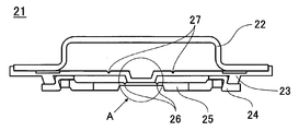
- FIG. 2 is a cross-sectional view of a sealing body according to an embodiment of the present invention.
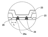
- FIG. 3 is an enlarged view of a portion A shown in FIG.
- FIG. 4 is a plan view of the sealing body according to the embodiment of the present invention as seen from the inside of the battery.
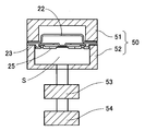
- FIG. 5 is a schematic view of an apparatus used for measuring the operating pressure.
- the electrode body 16 is accommodated inside the bottomed cylindrical outer can 20, and the sealing body 21 is caulked and fixed to the opening of the outer can 20 via the gasket 19. The inside is sealed.
- a non-aqueous electrolyte solution (not shown) is also housed inside the outer can 20 together with the electrode body 16. Most of the non-aqueous electrolyte penetrates into the electrode body 16.
- An upper insulating plate 17 and a lower insulating plate 18 are disposed above and below the electrode body 16, respectively.
- the sealing body 21, the electrode body 16, and the nonaqueous electrolyte will be described in detail.
- the sealing body 21 is configured by laminating a terminal cap 22, a valve body 23, an annular insulating member 24, and a terminal plate 25. As shown in FIGS. 3 and 4, the valve body 23 and the terminal plate 25 are welded to each other so that the planar shape of the welded portion 28 is annular. An annular thin portion 26 is formed in the terminal plate 25 so as to surround the welded portion 28. The valve body 23 is also formed with an annular thin portion 27. A terminal cap 22 is placed on the valve body 23, and its flange portion is welded to the valve body 23 by laser. In this case, it is not necessary to weld the entire circumference of the flange portion, and it is sufficient to weld several points in a spot shape.
- the current interruption mechanism operates as follows.
- a vent hole is formed in the terminal plate 25, and the valve body 23 receives the pressure when the battery internal pressure rises. Therefore, the terminal plate 25 is pulled by the valve body 23 as the battery internal pressure increases, and the thin portion 26 of the terminal plate 25 breaks when the battery internal pressure reaches a predetermined value. Then, since the outer peripheral portions of the valve body 23 and the terminal plate 25 are insulated by the insulating member 24, the current path between the valve body 23 and the terminal plate 25 is interrupted. When the battery internal pressure further rises, the valve body 23 is broken starting from the thin portion 27 formed in the valve body 23, and the gas inside the battery is released to the outside. Thus, the valve body 23 functions as an explosion-proof valve.
- the valve body 23 can be a rupture plate that breaks when the battery internal pressure reaches a predetermined value. In this case, the valve body 23 functions as an explosion-proof valve without the thin portion 27.
- valve body 23 Since the valve body 23 is required to have a function of deforming as the battery internal pressure increases, it is preferable to use a metal having excellent flexibility. In the case of a non-aqueous electrolyte secondary battery, it is preferable to use aluminum or an aluminum alloy for the valve body 23 and the terminal plate 25 in consideration of corrosion resistance when exposed to the positive electrode potential in the non-aqueous electrolyte.
- the insulating member 24 can be made of a material that can ensure insulation between the valve body 23 and the terminal plate 25 and does not affect the battery characteristics.
- the material used for the insulating member 24 is preferably a polymer resin, and specific examples include polypropylene (PP) resin and polybutylene terephthalate (PBT) resin.
- the insulating member 24 has a Z-shaped cross section, and the valve body 23 is provided with an annular protrusion. Thereby, the valve body 23, the terminal board 25, and the insulating member 24 can be fixed in three-pieces.
- the insulating member 24 may be a flat insulating plate. In this case, an annular protrusion is not necessary on the valve body.
- the central part of the valve body 23 protrudes toward the terminal plate 25. This configuration is employed to facilitate welding of the valve body 23 and the terminal plate 25. It is preferable that at least one of the valve body 23 and the terminal plate 25 protrudes toward the other party.
- the valve body 23 and the terminal plate 25 are welded to each other so that the planar shape of the welded portion 28 is annular.
- Laser welding is preferably used for welding, and a fiber laser is preferably used for the laser.
- the welded portion 28 is formed as a melt mark as shown in FIG. 3 when the valve body 23 and the terminal plate 25 are welded.
- the welded portion 28 can be observed with the naked eye, the outermost edge of the welded portion 28 can be more clearly specified by magnifying and observing the cross section of the sealing body 21 with an optical microscope.
- the cross-sectional shape of the welded portion 28 is not particularly limited, but is preferably symmetrical.
- the present invention is characterized in that the distance L from the outermost edge 28a of the welded portion 28 to the thinnest portion 26 of the thinned portion 26 is 1 mm or less.
- the said distance L is on the plane of the terminal board 25 as shown in FIG.3 and FIG.4. Refers to the distance.
- the cross-sectional shape of the thin portion 26 is not particularly limited, it can be V-shaped or U-shaped, and V-shape is particularly preferable.
- the thinnest portion 26 has the thinnest remaining thickness formed in a planar shape, the portion closest to the outermost edge 28a among the thinnest remaining thickness is used as the reference for the distance L.
- the planar shape of the thin portion 26 and the welded portion 28 formed on the terminal plate 25 is preferably a perfect circle, but may be another annular planar shape such as an ellipse.
- the planar shapes of the thin portion 26 and the welded portion 28 are preferably similar to each other. Thereby, the distance of the thin part 26 and the welding part 28 can be made uniform, and the effect of this invention is exhibited more effectively.
- the planar shape of the thin-walled portion 26 and the welded portion 28 is preferably an annular shape, but the effect of the present invention is also exerted in the same manner even when a C-shape with a part of the annular shape being discontinuous.
- the terminal cap 22 is used as a constituent member of the sealing body 21, but the terminal cap 22 can be made of a metal plate made of, for example, iron or stainless steel. Since the terminal cap 22 functions as an external terminal connected to an external device or the like, it is preferable to use a material having high mechanical strength for the terminal cap 22.
- the electric current interruption mechanism can be comprised with a valve body, a terminal board, and an insulating member
- the sealing body of this invention can also be comprised only from these three members.
- the valve body is used as the external terminal, it is possible to provide a sealed secondary battery having excellent gas releasing ability when the valve body is broken.
- the electrode body 16 is manufactured by winding a positive electrode plate 11 and a negative electrode plate 13 with a separator 15 interposed therebetween.
- the positive electrode plate 11 can be manufactured as follows, for example. First, the positive electrode active material and the binder are kneaded uniformly in the dispersion medium to prepare a positive electrode mixture slurry. It is preferable to use polyvinylidene fluoride as the binder and N-methylpyrrolidone as the dispersion medium. It is preferable to add a conductive agent such as graphite or carbon black to the positive electrode mixture slurry. This positive electrode mixture slurry is applied on a positive electrode current collector and dried to form a positive electrode mixture layer. In that case, the positive electrode collector exposed part in which the positive mix layer is not formed in a part of the positive electrode collector is provided. The positive electrode mixture layer is compressed with a roller to obtain the positive electrode plate 11. Finally, the positive electrode lead 12 is connected to the exposed portion of the positive electrode current collector.
- a lithium transition metal composite oxide capable of inserting and extracting lithium ions can be used.
- the lithium transition metal composite oxide include general formula LiMO 2 (M is at least one of Co, Ni, and Mn), LiMn 2 O 4, and LiFePO 4 . These can be used alone or in admixture of two or more, and at least one selected from the group consisting of Al, Ti, Mg, and Zr can be added, or substituted with a transition metal element. it can.
- the negative electrode plate 13 can be produced, for example, as follows. First, a negative electrode active material and a binder are kneaded so as to be uniform in a dispersion medium to prepare a negative electrode mixture slurry. It is preferable to use a styrene-butadiene copolymer or a modified product thereof as the binder and water as the dispersion medium. It is preferable to add a thickener such as carboxymethylcellulose to the negative electrode mixture slurry. This negative electrode mixture slurry is applied onto a negative electrode current collector and dried to form a negative electrode mixture layer. In that case, the negative electrode collector exposure part in which the negative mix layer is not formed in a part of negative electrode collector is provided. The negative electrode mixture layer is compressed with a roller to obtain the negative electrode plate 13. Finally, the negative electrode lead 14 is connected to the negative electrode current collector exposed portion.
- a thickener such as carboxymethylcellulose
- a carbon material that can occlude and release lithium ions or a metal material that can be alloyed with lithium can be used.
- the carbon material include graphite such as natural graphite and artificial graphite.
- the metal material include silicon and tin, and oxides thereof. The carbon material and the metal material can be used alone or in admixture of two or more.
- a microporous film mainly composed of polyolefin such as polyethylene (PE) or polypropylene (PP) can be used.
- the microporous membrane can be used singly or as a laminate of two or more layers.
- a layer mainly composed of polyethylene (PE) having a low melting point is used as an intermediate layer and polypropylene (PP) having excellent oxidation resistance is used as a surface layer.
- inorganic particles such as aluminum oxide (Al 2 O 3 ), titanium oxide (TiO 2 ), and silicon oxide (SiO 2 ) can be added to the separator 15.
- Such inorganic particles can be carried in the separator and can be applied together with a binder on the separator surface.
- non-aqueous electrolyte a solution obtained by dissolving a lithium salt as an electrolyte salt in a non-aqueous solvent can be used.
- a cyclic carbonate, a chain carbonate, a cyclic carboxylic acid ester and a chain carboxylic acid ester can be used, and it is preferable to use a mixture of two or more.
- the cyclic carbonate include ethylene carbonate (EC), propylene carbonate (PC), and butylene carbonate (BC).
- a cyclic carbonate in which part of hydrogen is substituted with fluorine, such as fluoroethylene carbonate (FEC) can also be used.
- the chain carbonate include dimethyl carbonate (DMC), ethyl methyl carbonate (EMC), diethyl carbonate (DEC), and methyl propyl carbonate (MPC).
- Examples of cyclic carboxylic acid esters include ⁇ -butyrolactone ( ⁇ -BL) and ⁇ -valerolactone ( ⁇ -VL).
- Examples of chain carboxylic acid esters include methyl pivalate, ethyl pivalate, methyl isobutyrate and methyl Pionate is exemplified.
- LiPF 6 , LiBF 4 , LiCF 3 SO 3 , LiN (CF 3 SO 2 ) 2 , LiN (C 2 F 5 SO 2 ) 2 , LiN (CF 3 SO 2 ) (C 4 F 9 SO 2 ) , LiC (CF 3 SO 2 ) 3 , LiC (C 2 F 5 SO 2 ) 3 , LiAsF 6 , LiClO 4 , Li 2 B 10 Cl 10 and Li 2 B 12 Cl 12 are exemplified.
- LiPF 6 is particularly preferable, and the concentration in the nonaqueous electrolytic solution is preferably 0.5 to 2.0 mol / L.
- Other lithium salts such as LiBF 4 may be mixed with LiPF 6 .
- Example 1 (Preparation of sealing body)
- the terminal cap 22, the valve body 23, and the terminal plate 25 were produced by pressing a metal plate.
- the terminal cap 22 was made of iron, and the valve body 23 and the terminal plate 25 were made of aluminum.
- projecting portions were formed at the central portion and the outer peripheral portion of the valve body 23, and an annular thin portion 27 was formed around the projecting portion at the central portion.
- the thin portion 27 is a starting point for breaking the valve body 23 when the battery internal pressure further increases after the operation of the current interrupting mechanism.
- a thin region was formed in the central portion of the terminal plate 25, and a thin portion 26 having a circular planar shape and a V-shaped cross section was formed in the region.
- the terminal board 25 is provided with a vent hole.
- the thin wall portion 26 was adjusted to have a remaining thickness such that the operating pressure of the current interrupting mechanism was 2.5 MPa.
- the insulating member 24 was manufactured by processing a plate material made of polybutylene terephthalate (PBT) resin so that the cross-sectional shape was Z-shaped by thermoforming.
- PBT polybutylene terephthalate
- the valve body 23 and the insulating member 24 are fitted. And the terminal plate 25 were fixed to each other.
- the protrusion of the central portion of the valve body 23 was brought into contact with the thin region of the central portion of the terminal plate, and the valve body 23 and the terminal plate 25 were welded by irradiating laser from the terminal plate 25 side.
- the welded portion 28 was formed on the terminal plate 25 by welding so that the planar shape was annular as shown in FIG.
- the welded portion 28 is formed as a melt mark from the terminal plate 25 to the valve body 23.
- the distance L from the outermost edge 28a of the welded portion 28 to the portion with the thinnest remaining thickness of the thin portion 26 was adjusted to be 0.5 mm.
- the terminal cap 22 was disposed on the valve body 23, the flange portion of the terminal cap 22 was irradiated with laser, and the terminal cap 22 was welded to the valve body 23 to produce the sealing body 21 according to Example 1. .
- Example 2 A sealing body 21 according to Example 2 was produced in the same manner as Example 1 except that the distance L was 1.0 mm.
- Comparative Example 1 A sealing body according to Comparative Example 1 was produced in the same manner as in Example 1 except that the distance L was 1.5 mm.
- Comparative Example 2 A sealing body according to Comparative Example 2 was produced in the same manner as in Example 1 except that the distance L was set to 2.0 mm.
- the sealing body was fixed to a fixing jig 50 having a pressing part 51 and a receiving part 52.
- the receiving part 52 is fixed to a part of the measuring apparatus, and the airtightness of the space S surrounded by the valve body 23 and the receiving part 52 is secured by pressurizing the pressing part 51 from above with an air cylinder.
- Nitrogen gas was supplied at a constant speed via a regulator 53 from a gas cylinder 54 filled with nitrogen gas in the space S.
- the pressure in the space S when the current path between the terminal cap and the terminal plate was interrupted during the supply of nitrogen gas was defined as the operating pressure of the current interrupting mechanism of the sealing body.
- the working pressures of 30 sealing bodies were measured for each of Examples 1 and 2 and Comparative Examples 1 and 2. Table 1 shows the average value, the minimum value, the maximum value, and the variation range of the working pressure in each example and comparative example.
- the variation range is a value obtained by subtracting the minimum value from the maximum value of the operating pressure.
Landscapes
- Chemical & Material Sciences (AREA)
- Chemical Kinetics & Catalysis (AREA)
- Electrochemistry (AREA)
- General Chemical & Material Sciences (AREA)
- Engineering & Computer Science (AREA)
- Manufacturing & Machinery (AREA)
- Gas Exhaust Devices For Batteries (AREA)
- Sealing Battery Cases Or Jackets (AREA)
- Connection Of Batteries Or Terminals (AREA)
Abstract
Description
(封口体の作製)
端子キャップ22、弁体23及び端子板25は金属板のプレス加工により作製した。端子キャップ22には鉄を、弁体23及び端子板25にはアルミニウムを用いた。プレス加工により、弁体23の中央部と外周部に突出部を形成し、中央部の突出部の周囲に環状の薄肉部27を形成した。この薄肉部27は電流遮断機構の作動後に電池内圧がさらに上昇した場合に弁体23が破断する起点となるものである。そして端子板25の中央部には厚みの薄い領域を形成し、その領域内に平面形状が環状で断面形状がV字状の薄肉部26を形成した。また、端子板25には通気孔を設けた。薄肉部26は電流遮断機構の作動圧が2.5MPaとなるように残肉厚みを調整した。
距離Lを1.0mmとしたこと以外は実施例1と同様にして実施例2に係る封口体21を作製した。
距離Lを1.5mmとしたこと以外は実施例1と同様にして比較例1に係る封口体を作製した。
距離Lを2.0mmとしたこと以外は実施例1と同様にして比較例2に係る封口体を作製した。
上記のようにして作製した実施例1及び2、並びに比較例1及び2に係る封口体各30個の作動圧を測定した。作動圧の測定は次のように行った。

11 正極板
12 正極リード
13 負極板
14 負極リード
15 セパレータ
16 電極体
17 上部絶縁板
18 下部絶縁板
19 ガスケット
20 外装缶
21 封口体
22 端子キャップ
23 弁体
24 絶縁部材
25 端子板
26、27 薄肉部
28 溶接部
28a 溶接部の最外縁
Claims (7)
- 電極体及び電解液を収容する有底筒状の外装缶と、
外装缶の開口部にかしめ固定される封口体と、
を備える密閉型電池において、
前記封口体は、少なくとも弁体、前記弁体よりも電池内方側に配置されると共に前記弁体の中央部に溶接される端子板、並びに前記弁体及び前記端子板のそれぞれの外周部に介在する環状の絶縁部材、を含み、
前記端子板が前記弁体との溶接時に溶融痕として形成された溶接部、及び前記溶接部の周囲に形成された薄肉部を有し、
前記溶接部の最外縁から前記薄肉部の残肉厚みが最も薄い部分までの距離が1mm以下である、
密閉型電池。 - 前記溶接部及び前記薄肉部のそれぞれの平面形状は環状及びC字状のいずれか一方である請求項1記載の密閉型電池。
- 前記溶接部及び前記薄肉部の平面形状は環状である請求項1又は2に記載の密閉型電池。
- 前記薄肉部の平面形状は前記溶接部と相似形である請求項1から3のいずれかに記載の密閉型電池。
- 前記薄肉部の断面形状はV字状又はU字状である請求項1から4のいずれかに記載の密閉型電池。
- 前記薄肉部は前記端子板の電池外方側に形成されている請求項1から5のいずれかに記載の密閉型電池。
- 前記封口体は最外部に端子キャップを有する請求項1から6のいずれかに記載の密閉型電池。
Priority Applications (3)
| Application Number | Priority Date | Filing Date | Title |
|---|---|---|---|
| JP2017504849A JPWO2016143287A1 (ja) | 2015-03-06 | 2016-02-26 | 密閉型電池 |
| CN201680012173.2A CN107251274A (zh) | 2015-03-06 | 2016-02-26 | 密闭型电池 |
| US15/547,921 US20180026238A1 (en) | 2015-03-06 | 2016-02-26 | Sealed batteries |
Applications Claiming Priority (2)
| Application Number | Priority Date | Filing Date | Title |
|---|---|---|---|
| JP2015-044186 | 2015-03-06 | ||
| JP2015044186 | 2015-03-06 |
Publications (1)
| Publication Number | Publication Date |
|---|---|
| WO2016143287A1 true WO2016143287A1 (ja) | 2016-09-15 |
Family
ID=56879351
Family Applications (1)
| Application Number | Title | Priority Date | Filing Date |
|---|---|---|---|
| PCT/JP2016/001046 Ceased WO2016143287A1 (ja) | 2015-03-06 | 2016-02-26 | 密閉型電池 |
Country Status (4)
| Country | Link |
|---|---|
| US (1) | US20180026238A1 (ja) |
| JP (1) | JPWO2016143287A1 (ja) |
| CN (1) | CN107251274A (ja) |
| WO (1) | WO2016143287A1 (ja) |
Cited By (4)
| Publication number | Priority date | Publication date | Assignee | Title |
|---|---|---|---|---|
| WO2021124995A1 (ja) * | 2019-12-18 | 2021-06-24 | 三洋電機株式会社 | 円筒形電池 |
| JPWO2021145247A1 (ja) * | 2020-01-17 | 2021-07-22 | ||
| WO2025069835A1 (ja) * | 2023-09-27 | 2025-04-03 | パナソニックIpマネジメント株式会社 | 円筒形電池 |
| EP4700952A1 (en) * | 2024-08-22 | 2026-02-25 | AESC Japan Ltd. | Secondary battery, battery pack and electronic apparatus |
Families Citing this family (6)
| Publication number | Priority date | Publication date | Assignee | Title |
|---|---|---|---|---|
| KR102520538B1 (ko) * | 2017-12-05 | 2023-04-11 | 삼성에스디아이 주식회사 | 이차 전지 |
| CN108183183A (zh) * | 2018-01-19 | 2018-06-19 | 东莞市奕东电子有限公司 | 一种车载锂电池的电池盖帽结构、电池单体及电池组 |
| US10371181B1 (en) | 2018-04-06 | 2019-08-06 | Ford Global Technologies, Llc | Traction battery enclosure clamping device and securing method |
| KR102389412B1 (ko) * | 2018-11-28 | 2022-04-22 | 주식회사 엘지에너지솔루션 | 이차전지 및 그 이차전지 제조방법 |
| US11799158B2 (en) * | 2020-12-29 | 2023-10-24 | Zhuhai Zhi Li Battery Co., Ltd. | Top plate for laser welded lithium-ion button cell battery |
| CN115832596B (zh) * | 2021-10-19 | 2025-05-16 | 宁德时代新能源科技股份有限公司 | 电池单体 |
Citations (10)
| Publication number | Priority date | Publication date | Assignee | Title |
|---|---|---|---|---|
| JPH07105933A (ja) * | 1993-10-06 | 1995-04-21 | Hitachi Maxell Ltd | 防爆形密閉電池 |
| JPH08115715A (ja) * | 1994-10-14 | 1996-05-07 | Hitachi Maxell Ltd | 防爆形密閉電池 |
| JPH10233198A (ja) * | 1997-02-18 | 1998-09-02 | Toshiba Battery Co Ltd | 非水電解液電池 |
| JPH11260334A (ja) * | 1998-03-10 | 1999-09-24 | Matsushita Electric Ind Co Ltd | 密閉型電池用防爆封口板ならびにその製造法およびそれを用いた密閉型電池 |
| JP2000149918A (ja) * | 1998-11-13 | 2000-05-30 | Matsushita Electric Ind Co Ltd | 二次電池 |
| JP2000223103A (ja) * | 1999-02-01 | 2000-08-11 | Hitachi Maxell Ltd | 密閉型電池 |
| JP2009140870A (ja) * | 2007-12-10 | 2009-06-25 | Sanyo Electric Co Ltd | 密閉電池用端子及び密閉電池 |
| JP2013101890A (ja) * | 2011-11-09 | 2013-05-23 | Toyota Motor Corp | 密閉型電池 |
| WO2014033806A1 (ja) * | 2012-08-27 | 2014-03-06 | トヨタ自動車株式会社 | 密閉型二次電池 |
| WO2015068353A1 (ja) * | 2013-11-05 | 2015-05-14 | 三洋電機株式会社 | 密閉型電池用封口体及び密閉型電池 |
Family Cites Families (1)
| Publication number | Priority date | Publication date | Assignee | Title |
|---|---|---|---|---|
| JP5420219B2 (ja) * | 2008-09-30 | 2014-02-19 | 三洋電機株式会社 | 密閉型電池及びその製造方法 |
-
2016
- 2016-02-26 US US15/547,921 patent/US20180026238A1/en not_active Abandoned
- 2016-02-26 CN CN201680012173.2A patent/CN107251274A/zh active Pending
- 2016-02-26 WO PCT/JP2016/001046 patent/WO2016143287A1/ja not_active Ceased
- 2016-02-26 JP JP2017504849A patent/JPWO2016143287A1/ja active Pending
Patent Citations (10)
| Publication number | Priority date | Publication date | Assignee | Title |
|---|---|---|---|---|
| JPH07105933A (ja) * | 1993-10-06 | 1995-04-21 | Hitachi Maxell Ltd | 防爆形密閉電池 |
| JPH08115715A (ja) * | 1994-10-14 | 1996-05-07 | Hitachi Maxell Ltd | 防爆形密閉電池 |
| JPH10233198A (ja) * | 1997-02-18 | 1998-09-02 | Toshiba Battery Co Ltd | 非水電解液電池 |
| JPH11260334A (ja) * | 1998-03-10 | 1999-09-24 | Matsushita Electric Ind Co Ltd | 密閉型電池用防爆封口板ならびにその製造法およびそれを用いた密閉型電池 |
| JP2000149918A (ja) * | 1998-11-13 | 2000-05-30 | Matsushita Electric Ind Co Ltd | 二次電池 |
| JP2000223103A (ja) * | 1999-02-01 | 2000-08-11 | Hitachi Maxell Ltd | 密閉型電池 |
| JP2009140870A (ja) * | 2007-12-10 | 2009-06-25 | Sanyo Electric Co Ltd | 密閉電池用端子及び密閉電池 |
| JP2013101890A (ja) * | 2011-11-09 | 2013-05-23 | Toyota Motor Corp | 密閉型電池 |
| WO2014033806A1 (ja) * | 2012-08-27 | 2014-03-06 | トヨタ自動車株式会社 | 密閉型二次電池 |
| WO2015068353A1 (ja) * | 2013-11-05 | 2015-05-14 | 三洋電機株式会社 | 密閉型電池用封口体及び密閉型電池 |
Cited By (9)
| Publication number | Priority date | Publication date | Assignee | Title |
|---|---|---|---|---|
| WO2021124995A1 (ja) * | 2019-12-18 | 2021-06-24 | 三洋電機株式会社 | 円筒形電池 |
| JPWO2021124995A1 (ja) * | 2019-12-18 | 2021-06-24 | ||
| JP7686570B2 (ja) | 2019-12-18 | 2025-06-02 | パナソニックエナジー株式会社 | 円筒形電池 |
| US12347878B2 (en) | 2019-12-18 | 2025-07-01 | Panasonic Energy Co., Ltd. | Cylindrical battery |
| JPWO2021145247A1 (ja) * | 2020-01-17 | 2021-07-22 | ||
| JP7669293B2 (ja) | 2020-01-17 | 2025-04-28 | パナソニックエナジー株式会社 | 密閉電池 |
| WO2025069835A1 (ja) * | 2023-09-27 | 2025-04-03 | パナソニックIpマネジメント株式会社 | 円筒形電池 |
| EP4700952A1 (en) * | 2024-08-22 | 2026-02-25 | AESC Japan Ltd. | Secondary battery, battery pack and electronic apparatus |
| JP2026040356A (ja) * | 2024-08-22 | 2026-03-09 | 株式会社Aescジャパン | 二次電池、電池パック、および電子デバイス |
Also Published As
| Publication number | Publication date |
|---|---|
| CN107251274A (zh) | 2017-10-13 |
| JPWO2016143287A1 (ja) | 2017-12-28 |
| US20180026238A1 (en) | 2018-01-25 |
Similar Documents
| Publication | Publication Date | Title |
|---|---|---|
| US10615401B2 (en) | Cylindrical batteries | |
| JPWO2016143287A1 (ja) | 密閉型電池 | |
| JP6801645B2 (ja) | 円筒形電池 | |
| US10461304B2 (en) | Cylindrical battery | |
| US11069916B2 (en) | Cylindrical battery | |
| CN104126238B (zh) | 封闭式二次电池 | |
| JP6490053B2 (ja) | 円筒形密閉電池及び電池パック | |
| CN106030850B (zh) | 圆筒形密闭电池 | |
| CN111247660B (zh) | 圆筒形电池 | |
| US10601002B2 (en) | Cylindrical battery and method for producing the same | |
| JPWO2018180828A1 (ja) | 円筒形電池 | |
| CN111194491B (zh) | 圆筒形电池 | |
| JP6477334B2 (ja) | 円筒形電池 | |
| JP2012209024A (ja) | 密閉型電池 |
Legal Events
| Date | Code | Title | Description |
|---|---|---|---|
| 121 | Ep: the epo has been informed by wipo that ep was designated in this application |
Ref document number: 16761265 Country of ref document: EP Kind code of ref document: A1 |
|
| WWE | Wipo information: entry into national phase |
Ref document number: 15547921 Country of ref document: US |
|
| ENP | Entry into the national phase |
Ref document number: 2017504849 Country of ref document: JP Kind code of ref document: A |
|
| NENP | Non-entry into the national phase |
Ref country code: DE |
|
| 122 | Ep: pct application non-entry in european phase |
Ref document number: 16761265 Country of ref document: EP Kind code of ref document: A1 |