WO2016140334A1 - 形状制御されたナノシート及びその製造方法 - Google Patents
形状制御されたナノシート及びその製造方法 Download PDFInfo
- Publication number
- WO2016140334A1 WO2016140334A1 PCT/JP2016/056706 JP2016056706W WO2016140334A1 WO 2016140334 A1 WO2016140334 A1 WO 2016140334A1 JP 2016056706 W JP2016056706 W JP 2016056706W WO 2016140334 A1 WO2016140334 A1 WO 2016140334A1
- Authority
- WO
- WIPO (PCT)
- Prior art keywords
- layer
- nanosheet
- multilayer structure
- stretchable
- sheet
- Prior art date
- Legal status (The legal status is an assumption and is not a legal conclusion. Google has not performed a legal analysis and makes no representation as to the accuracy of the status listed.)
- Ceased
Links
Images





Classifications
-
- B—PERFORMING OPERATIONS; TRANSPORTING
- B32—LAYERED PRODUCTS
- B32B—LAYERED PRODUCTS, i.e. PRODUCTS BUILT-UP OF STRATA OF FLAT OR NON-FLAT, e.g. CELLULAR OR HONEYCOMB, FORM
- B32B27/00—Layered products comprising a layer of synthetic resin
- B32B27/30—Layered products comprising a layer of synthetic resin comprising vinyl (co)polymers; comprising acrylic (co)polymers
-
- B—PERFORMING OPERATIONS; TRANSPORTING
- B32—LAYERED PRODUCTS
- B32B—LAYERED PRODUCTS, i.e. PRODUCTS BUILT-UP OF STRATA OF FLAT OR NON-FLAT, e.g. CELLULAR OR HONEYCOMB, FORM
- B32B37/00—Methods or apparatus for laminating, e.g. by curing or by ultrasonic bonding
- B32B37/14—Methods or apparatus for laminating, e.g. by curing or by ultrasonic bonding characterised by the properties of the layers
- B32B37/16—Methods or apparatus for laminating, e.g. by curing or by ultrasonic bonding characterised by the properties of the layers with all layers existing as coherent layers before laminating
Definitions
- the present invention relates to a multilayer structure sheet including a nanosheet layer and a stretchable layer and having a wound structure, and a method for producing the same.
- nanosheet An ultra-thin polymer film (hereinafter referred to as “nanosheet”) is a sheet made of a polymer such as polylactic acid and having a thickness of several tens to several hundreds of nanometers. It follows the surface shape of the organ and can be applied by van der Waals force or surface tension without an adhesive.
- Nanosheets are used by being attached to affected areas and incisions as wound protection materials (Non-Patent Documents 1 and 2).
- nanosheets can be used as a wound protection material in endoscopic surgery, and as a transplant base material for cell transplantation into living tissue (such as under the retina). Is being developed and studied (Non-Patent Documents 3-5).
- the nanosheet is thin and flexible, it cannot be restored to its planar shape by itself when it is deformed by bending in the liquid. Therefore, it is not easy to suppress the deformation of the nanosheet, maintain the planar shape, and stick to the target site. Furthermore, when the target site is a narrow environment in the living body, the nanosheet cannot be directly manipulated, so that it is more difficult to apply it while maintaining the planar shape.
- An object of the present invention is to provide a nanosheet capable of maintaining a planar shape and a manufacturing method thereof.
- the inventors of the present invention have received viscous resistance and buoyancy in the liquid, and these forces are a restoring force (that is, a bending moment) that causes the nanosheet in a deformed state to return to a planar shape in the liquid. In order to balance, it was found that the nanosheet once deformed cannot be restored to a planar shape by itself.
- the present inventors have studied to increase the bending moment of the nanosheet and maintain the planar shape of the nanosheet, and as a result, by combining a layer (sheet) having a large second moment of section with the nanosheet, the film of the nanosheet itself is obtained. It has been found that the bending moment of the nanosheet can be increased without increasing the thickness, thereby maintaining the planar shape in the liquid.
- nanosheets combined with other layers lose their thinness and flexibility, making them difficult to store in tubules used for nanosheet delivery (eg, syringes and catheters). It has been found that the nanosheet can be solved by forming a wound structure. As a result of studying a simple method in which the nanosheet and another layer are wound structures, the present inventors have bonded and laminated the nanosheet to another layer that is distorted and applied with internal stress to form a multilayer structure. Then, it was found that the multilayer structure can be wound spontaneously by recovering the strain and utilizing the stress difference of each layer, and the desired wound structure can be formed.
- a method for producing a multilayer structure sheet comprising a nanosheet layer and a stretchable layer and having a wound structure, (I) a step of laminating a nanosheet layer on a stretchable layer that generates strain and imparts internal stress to form a multilayer structure; (Ii) then recovering the strain of the stretch layer in the multilayer structure and thereby winding the multilayer structure; The above method.
- the multilayer structure sheet further includes a support layer, and in step (i), the support layer / the nanosheet layer / the stretchable layer is laminated in this order, or the nanosheet layer / the support layer / the stretchable layer is laminated in this order. The method of [1].
- step (i) a tensile force is applied to generate a tensile strain, and a support layer (if present) and a nanosheet layer are laminated on an elastic layer to which an internal stress is applied.
- step (ii) the multilayer structure is cut out from the environment in which a tensile force is applied to the stretchable layer, and the tensile strain of the stretchable layer in the cut-out multilayered structure is recovered, whereby the cut-out multilayered structure is stretched.
- winding is performed based on a difference in internal stress between the layer and the support layer (if present) and / or the nanosheet layer.
- a multilayer structure sheet comprising a nanosheet layer and a stretchable layer and having a wound structure.
- a multilayer structure sheet including nanosheets having a wound structure and capable of developing nanosheets into a planar shape by a self-contact / non-contact manner.
- the multilayer structure sheet can be easily produced.
- FIG. 1 is a schematic diagram of a method for producing a multilayer structure sheet including a nanosheet layer, a support layer, and a stretchable layer using a tensile force.
- B A step of recovering the tensile strain of the stretchable layer in the multilayer structure and thereby winding the multilayer structure spontaneously.
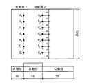
- FIG. 2 is a schematic diagram showing a cut surface and measurement points used for evaluating the film thickness uniformity of a polyvinyl alcohol (hereinafter referred to as “PVA”) sheet obtained by a constant amount dropping method.
- PVA polyvinyl alcohol
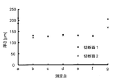
- FIG. 3 is a graph showing the measurement results of the film thickness at the measurement points of each cut surface of the PVA sheet obtained when the dropping amount is 4000 ⁇ L.
- FIG. 4 shows a stress strain diagram obtained as a result of a tensile test of a PVA sheet (film thickness 63.5 ⁇ m).
- FIG. 5 is a graph showing the change in film thickness at each measurement point on the cut surface due to dissolution of the PVA sheet.
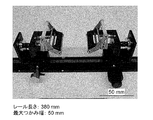
- FIG. 6 shows a photograph of a tension device for applying tensile strain to the stretchable layer.
- FIG. 7 is a photograph showing a method for producing a multilayer structure sheet. (A) The state which pulled and fixed the PVA sheet used as an elastic layer using the tension
- pulling apparatus is shown.
- FIG. 8 shows a photograph of a multilayered sheet having a manufactured wound structure (cylindrical shape). In the multilayer structure sheet, the frame line of the nanosheet layer is colored for easy viewing.
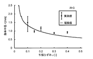
- FIG. 9 shows a comparison result between the measured value and the theoretical value of the radius of curvature (r) obtained when the thickness of the support layer and the stretchable layer is constant and the tensile strain ( ⁇ ) applied to the stretchable layer is changed.
- r radius of curvature
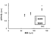
- FIG. 10 shows a comparison result between the measured value and the theoretical value of the radius of curvature (r) obtained when the tensile strain applied to the stretchable layer is constant and the film thickness (t) of the support layer and the stretchable layer is changed.
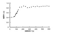
- FIG. 11 is a graph showing a change with time of the development rate ( ⁇ ) in water of a multilayer structure sheet having a wound structure.
- Nanosheet layer means a layer containing a nanosheet or consisting of the nanosheet.
- Nanosheet means a sheet having a thickness of less than 500 nm, preferably about 20 nm to 300 nm, more preferably about 50 nm to 200 nm.
- the nanosheet is made of a polymer such as polylactic acid, polyglycolic acid, polyhydroxybutyric acid, polycaprolactone, polybutylene succinate, polydioxanone, polydimethylsiloxane, polymethyl methacrylate, polystyrene, polyvinyl acetate, poly (3,4-ethylene). Dioxythiophene), proteins (collagen, gelatin, laminin, fibronectin, elastin), polysaccharides (chitosan, alginic acid, hyaluronic acid, chondroitin sulfate, cellulose), nucleic acids (DNA, RNA) and copolymers thereof It can be produced using an appropriate one.
- the nanosheet is made of a biodegradable polymer.
- the method for producing the nanosheet layer is not particularly limited, and can be performed using a conventionally known general method (for example, spin coating method).
- a polymer or a component of the polymer for example, a monomer that is a component of the polymer
- an appropriate solvent for example, And dissolved in a concentration of 1 mg / mL to 100 mg / mL, preferably 5 mg / mL to 40 mg / mL in dichloromethane, chloroform, acetone, ethyl acetate, etc.
- a substrate for example, polydimethylsiloxane (PDMS), metal, silicon, glass, etc.
- the thickness of the polymer applied on the substrate surface can be adjusted, and the thickness of the nanosheet layer as the final product can be adjusted.
- the nanosheet layer formed on the substrate can be peeled off from the substrate by any means. Although it is not easy to physically peel off the nanosheet layer from the substrate using tweezers or the like due to its thinness, for example, by immersing in isopropyl alcohol (IPA), IPA enters between the substrate and the nanosheet layer, It can be removed spontaneously from the substrate.
- IPA isopropyl alcohol
- the shape and size of the nanosheet layer can be appropriately selected according to the purpose.
- the diameter or the length of the longest diagonal line is about 10 ⁇ m to 50 mm, preferably about 100 ⁇ m to 20 mm, more preferably about 1 mm to 10 mm. (It is not limited to these).
- the “shape and size” means the shape and size of a surface that intersects the thickness direction perpendicularly.
- the nanosheet layer can carry nanoparticles made of a magnetic material.
- the nanosheet layer By supporting nanoparticles made of a magnetic material on the nanosheet layer, the nanosheet layer can be moved / assembled using magnetic force, and operability can be improved.
- the nanoparticles made of a magnetic material have a particle diameter of about 1 nm to 500 nm, preferably about 1 nm to 50 nm.
- Nanoparticles made of a magnetic material can be supported on a nanosheet layer as a final product by being included in a solution of the above-described biocompatible polymer or the like and coated on the substrate surface together with the biocompatible polymer or the like.
- Nanoparticles made of a magnetic substance can be contained in a solution such as a biocompatible polymer at a concentration of 0.1 mg / mL to 50 mg / mL, preferably 1 mg / mL to 25 mg / mL.
- a functional substance can be supported on the nanosheet layer.
- “Functional substance” means a substance (for example, protein, polypeptide, compound, etc.) having a function of controlling cell proliferation, differentiation, physiological activity, etc., or a substance that enables visualization of a nanosheet layer.
- Such functional substances include growth / growth factors (eg, fibroblast growth factor (FGF), epidermal growth factor (EGF), bone morphogenetic protein (BMP), nerve growth factor (NGF), brain-derived neurotrophic Factor (BDNF), etc.), intraocular pressure-lowering agent, neuroprotective agent, antibiotic, anticancer agent, visualization probe (contrast agent, nanoparticle, fluorescent dye, etc.).
- FGF fibroblast growth factor
- EGF epidermal growth factor
- BMP bone morphogenetic protein
- NGF nerve growth factor
- BDNF brain-derived neurotrophic Factor
- the nanosheet layer can be provided with functions such as controlling proliferation, differentiation, physiological activity and the like of cells derived from the functional substance.
- the functional substance can be bonded to the nanosheet layer using chemical or physical techniques.
- the chemical method includes chemical bonding via a functional group.
- a biocompatible polymer is modified in advance with an appropriate functional group (for example, amino group, carboxyl group, hydroxyl group, aldehyde group, etc.).
- a functional substance can be bonded to the obtained nanosheet layer through the introduced functional group.
- Examples of physical methods include electrostatic interaction, hydrophobic interaction, hydrogen bonding, intermolecular force and the like between the nanosheet layer and the functional substance.
- the surface of the nanosheet layer can be coated with an extracellular matrix that promotes cell adhesion and proliferation.
- extracellular matrix examples include type I collagen, type IV collagen, fibronectin, poly-D-lysine (PDL), laminin, poly-L-ornithine / laminin (PLO / LM) and the like.
- the multilayer structure sheet of the present invention includes nanosheet layers made of different polymers, nanosheet layers having different shapes and sizes, nanosheet layers carrying different substances (magnetic materials, functional substances, extracellular substrates, etc.), etc.
- a plurality of nanosheet layers having different functions can be stacked and included.
- nanosheet layer which consists of nanosheets may only be described as a nanosheet.
- the “support layer” includes or consists of a sheet made of a polymer having a thickness of less than 250 ⁇ m, preferably about 20 ⁇ m to 150 ⁇ m, more preferably about 50 ⁇ m to 100 ⁇ m. Means layer.
- a polymer that can be used for the sheet of the support layer those described in the above “(1) Nanosheet layer” can be used.
- a water-soluble polymer can be used. Any “water-soluble polymer” may be used as long as it is soluble in water. Preferably, those having biocompatibility are further included.
- water-soluble polymers examples include polyvinyl alcohol (PVA) or derivatives thereof, polyisopropylacrylamide or derivatives thereof, polyethers or derivatives thereof, polysaccharides, polymer electrolytes or salts thereof, and the like.
- PVA polyvinyl alcohol
- polyisopropylacrylamide or derivatives thereof
- polyethers or derivatives thereof polyethers or derivatives thereof
- polysaccharides polymer electrolytes or salts thereof, and the like.
- the method for producing the support layer is not particularly limited, and can be performed by using a conventionally known general method (for example, spin coating method, casting method, etc.) in the production of a sheet made of a water-soluble polymer.
- a conventionally known general method for example, spin coating method, casting method, etc.
- the polymer is added in an appropriate solvent (eg, dichloromethane, chloroform, acetone, ethyl acetate, water, etc.) at 1 mg / mL to 100 mg / mL, preferably 5 mg / mL.
- a substrate eg, polydimethylsiloxane (PDMS), metal, silicon, glass, etc.
- PDMS polydimethylsiloxane
- the thickness of the polymer coated on the substrate surface can be adjusted, and the thickness of the support layer as the final product can be adjusted.
- the polymer is dissolved in an appropriate solvent, and the polymer solution is applied onto the substrate by dropping or spraying, followed by drying.
- the amount of the polymer solution to be dropped or sprayed the thickness of the polymer coated on the substrate surface can be adjusted, and the thickness of the support layer as the final product can be adjusted.
- the support layer formed on the substrate can be peeled off from the substrate by any means, and may be physically peeled off from the substrate using tweezers or the like, for example, by immersing in isopropyl alcohol (IPA), You may peel off from a board
- IPA isopropyl alcohol
- the support layer may be combined with the nanosheet layer to increase the bending moment of the nanosheet layer.
- the shape and size of the support layer are not particularly limited, and the entire nanosheet layer in a state of being developed in a planar shape or its Supports a part (for example, 20% or more, 30% or more, 40% or more, 50% or more, 60% or more, 70% or more, 80% or more, 90% or more or more of the total area of the nanosheet layer) ( Any shape or size that can be backed is acceptable. Therefore, as long as the bending moment of the nanosheet layer can be increased in combination with the nanosheet layer, the support layer may have the same shape or size as the nanosheet layer, or may have a different shape or size. .
- the support layer is characterized in that the value of the reaction force bending moment when bending modification represented by the following formula is larger than the value obtained for the nanosheet layer.
- Reaction force bending moment when bending modified EI / ⁇ (Where E: Young's modulus, I: secondary moment of section, ⁇ : radius of curvature)
- the nanosheet layer and the support layer may be formed in advance as a two-layer structure. That is, the nanosheet layer is first formed on the substrate as described above, and then the support layer is formed on the nanosheet layer as described above, or the support layer is first formed on the substrate as described above, and then the support layer is formed. On top, a nanosheet layer is formed as described above.
- the formed two-layer structure may be physically peeled off from the substrate using tweezers or the like, or may be spontaneously peeled off from the substrate by dipping in, for example, isopropyl alcohol (IPA).
- IPA isopropyl alcohol
- the “stretchable layer” includes or consists of a sheet made of a polymer having a thickness of less than 250 ⁇ m, preferably about 20 ⁇ m to 150 ⁇ m, more preferably about 50 ⁇ m to 100 ⁇ m. Means layer.
- the “polymer” usable in the stretchable layer include those defined as “polymer” usable in the support layer.
- the method for producing the stretchable layer is not particularly limited, and can be performed by using a conventionally known general method (for example, spin coating method, casting method, etc.) in the production of the polymer sheet.
- the spin coating method and the casting method can be carried out in the same manner as the method for producing the support layer.
- the support layer formed on the substrate can be peeled off from the substrate by any means, and may be physically peeled off from the substrate using tweezers or the like, for example, by immersing in isopropyl alcohol (IPA), You may peel off from a board
- IPA isopropyl alcohol
- the stretchable layer and the support layer may be made of the same polymer or may be made of different polymers, and the thickness of the stretchable layer and the support layer may be the same or similar. , May be different.
- the stretchable layer and the support layer are composed of the same polymer and have the same or similar thickness. “Same degree” means that the thickness of one layer is less than twice the thickness of the other layer, or less than 1.5 times.
- the stretchable layer and the support layer are water-soluble polymers, these layers can simultaneously swell and stretch when dissolved in water, and this swelling and stretch can affect the development of the nanosheet layer into a planar shape. .
- the stretchable layer and the support layer from the same water-soluble polymer and having the same or similar thickness, the influence can be reduced.
- the shape and size of the stretchable layer are not particularly limited, and it is possible to generate strain, and in the state where strain is generated and internal stress is applied, the entire support layer and / or nanosheet layer or its Support (backing) a part (for example, 20% or more, 30% or more, 40% or more, 50% or more, 60% or more, 70% or more, 80% or more, 90% or more of the entire area) Any shape and size can be used.
- the stretchable layer when the value of the reaction force bending moment when bending modification represented by the above formula is larger than the value obtained for the nanosheet layer, the stretchable layer is used to maintain the planar shape of the nanosheet layer. Can be involved. In this case, since the stretchable layer also functions as a support layer, the support layer may or may not be present in the multilayer structure sheet of the present invention.
- the nanosheet layer, the support layer, and / or the stretchable layer can include a water-soluble sacrificial layer that is soluble in liquid (for example, in body fluid).
- a water-soluble sacrificial layer dissolves when the multilayer structure sheet is placed in the liquid, and can be used to separate each layer from the adjacent layer.
- each multilayer layer or any one of the layers includes a water-soluble sacrificial layer so as to be disposed between the nanosheet layer and the support layer and / or the stretch layer.
- the water-soluble sacrificial layer dissolves, and the support layer and / or the stretchable layer can be peeled from the nanosheet.
- the operability of the nanosheet layer can be improved by including a water-soluble sacrificial layer in the nanosheet layer and forming the nanosheet and the water-soluble sacrificial layer in advance as a two-layer structure.
- the water-soluble sacrificial layer can be produced using the above-mentioned “water-soluble polymer”, and a conventionally known general method (for example, spin coating method, casting method, etc.) is used in the production of a sheet made of the polymer.
- a conventionally known general method for example, spin coating method, casting method, etc.
- a water-soluble sacrificial layer may be formed on each layer, and / or a water-soluble sacrificial layer is first formed in the same manner on the substrate, and then each layer is formed on the water-soluble sacrificial layer as described above. Also good.
- Manufacturing method of multilayer structure sheet (I) a step of laminating a nanosheet layer or a nanosheet layer and a support layer on a stretchable layer that has been subjected to strain and imparted internal stress to form a multilayer structure; and (ii) recovering the strain of the stretchable layer in the multilayer structure; Thereby spontaneously winding the multilayer structure.
- strain is not limited as long as it can apply internal stress to the stretchable layer, and examples thereof include compressive strain and tensile strain, but tensile strain is preferable.
- tensile strain is preferable.
- FIG. 1 shows a schematic diagram of the production method of the present invention.
- step (i) when the nanosheet layer and the support layer are laminated, a tensile strain is generated in advance in the stretchable layer and a tensile internal stress is applied (FIG. 1 (a)).
- the tensile strain can be generated by pulling one or both of the opposite ends of the stretchable layer in a direction opposite to the facing direction.
- How much tensile strain is generated in the stretchable layer is desired in the types of polymers constituting the support layer and stretchable layer, the thickness of these layers, and the wound structure of the finally obtained multilayer structure sheet. It can be determined as appropriate based on the radius of curvature. For example, a multilayer structure sheet having a desired radius of curvature can be obtained by changing the tensile strain under the condition that the types of polymers constituting the support layer and the stretchable layer and the thickness of these layers are constant. The magnitude of the tensile strain that can be found.
- the conditions for obtaining a multilayer structure sheet having a desired radius of curvature under constant tensile strain conditions by changing the types of polymers constituting the support layer and the stretchable layer and the thickness of these layers can be found.
- the thickness and Young's modulus of the support layer and the stretch layer, and the stress strain diagram are measured, and then the tensile strain required to obtain the desired radius of curvature is calculated. It can be derived from the value.
- the radius of curvature is about 0.9 to 1 by setting the tensile strain to 0.1 to 0.4.
- a multilayer structure sheet having a wound structure of about 5 mm can be obtained.
- Lamination of the nanosheet layer and the support layer to the stretchable layer to which a tensile internal stress is applied may be performed in the order of stretchable layer / nanosheet layer / support layer, or in the order of stretchable layer / support layer / nanosheet layer. May be made.
- the stretchable layer and the support layer are water-soluble polymers, the effect of swelling / elongation on the dissolution of the water in these layers on the nanosheet layer is greater than the stacking in the order of stretchable layer / support layer / nanosheet layer. It can be reduced by laminating in the order of stretchable layer / nanosheet layer / support layer.
- each layer can be performed by dissolving a part of the adhesion surface of the stretchable layer and / or the support layer to give an adhesive force and thereby adhering to an adjacent layer.
- an adhesive force for adhering to the adjacent layer can be applied to the surface by spraying or applying 70% ethanol to the surface.
- the strain of the stretchable layer in the multilayer structure can be recovered by removing the tensile force applied to the stretchable layer in the multilayer structure.
- the removal of the tensile force is not particularly limited as long as the tensile strain in the stretchable layer in the multilayer structure can be recovered.
- the tensile force can be removed by moving one or both of the opposite ends of the stretchable layer in the direction opposite to the tensile direction.
- it can be performed by cutting the formed multilayer structure from an environment in which a tensile force is applied to the stretchable layer. Since the multilayer structure sheet can be adjusted to a desired shape and size, it is preferable to use a cutting means.
- the stretchable layer to which internal stress has been applied in advance by tensile force recovers and contracts by removing the tensile force, while the nanosheet layer and support layer to which similar internal stress is not applied are stretched and contracted. It does not shrink with the layers.
- the multilayer structure sheet can be wound spontaneously by utilizing the stress difference between the stretchable layer, the nanosheet layer, and the support layer in the multilayer structure sheet (FIG. 1B).
- spontaneous winding means winding based on the difference in stress between the nanosheet layer and the support layer and the stretchable layer, and is applied by applying external force to the multilayer structure sheet. (For example, mechanically rotating a multilayer structure sheet) is not meant.
- the portion (point) of the multilayer structure sheet that is finally cut off is on the side perpendicular to the pulling direction so that the cut multilayer structure sheet spontaneously rolls in one direction, or It is preferable to use a line perpendicular to the tensile direction assumed on the surface of the stretchable layer and a contact point of the multilayer structure sheet.
- the multilayer structure sheet can be cut out by any means, and scissors, cutter knives, knives, scalpels, lasers, and the like can be used.
- the shape and size to be cut off can be appropriately determined as long as a multilayer structure is included.
- the multilayer structure sheet of the present invention includes the nanosheet layer and the stretchable layer, and has a wound structure.
- the multilayer structure sheet includes a support layer
- the nanosheet layer, the support layer, and the stretchable layer may be laminated in the order of stretchable layer / nanosheet layer / support layer, or stretchable layer / support layer / nanosheet layer. They may be laminated in the order.
- the shape and size of each layer in the multilayer structure sheet may be different or the same.
- the multilayer structure sheet of the present invention When the multilayer structure sheet of the present invention is released into a liquid (for example, body fluid), it can be developed into a planar shape by itself or in a non-contact manner from the wound structure.
- a liquid for example, body fluid
- Self-powered or non-contact mode means that no artificial operation (for example, applying physical force using tweezers, etc.) is required to expand the multilayer structure sheet into a planar shape.
- no artificial operation for example, applying physical force using tweezers, etc.
- the multilayer structure sheet of the present invention has a wound structure, and can be sucked by a thin tube having an appropriate inner diameter depending on the size, and can be discharged from the thin tube. Thereby, the multilayer structure sheet of the present invention can be administered and delivered to a narrow environment in a living body using a thin tube.
- the “winding structure” include a cylindrical shape, a conical shape, and a truncated cone shape, but are not particularly limited.
- Examples of the “capillary tube” include an injection needle and a catheter.
- the size (gauge) and length of the “thin tube” can be appropriately selected according to factors such as the size of the multilayer structure sheet and the part into which the multilayer structure sheet is introduced. By utilizing the tubule, the multilayer structure sheet can be delivered to the subject minimally invasively.
- the nanosheet layer In the liquid (for example, body fluid), other layers are removed from the nanosheet layer, and finally the nanosheet layer can be attached to the target site.
- the removal may be performed by dissolving the support layer or the stretchable layer in the liquid by being made of a water-soluble polymer, or from the water-soluble polymer between the nanosheet layer and the other layers.
- This layer may be formed by providing a layer (water-soluble sacrificial layer), dissolving the sacrificial layer in the liquid, and peeling off the other layers.
- the nanosheet layer is made of a biodegradable polymer, the attached nanosheet layer is finally decomposed and absorbed in vivo.
- Example 1 Preparation of PVA sheet (1-1) Spin coating method A PVA solution in which PVA was dissolved in pure water at a concentration of 10 wt% was prepared, and this was dropped on a glass substrate and spin-coated for 10 seconds. went. Table 1 shows the number of rotations and the film thickness of the obtained PVA sheet when the rotation time of the spin coating was 10 seconds.
- the PVA sheet obtained by spin coating was able to be peeled off spontaneously by the IPA entering between the glass substrate and the glass substrate by immersing the glass substrate on which the PVA sheet was formed in IPA.
- the film thickness uniformity evaluation of the PVA sheet was performed as follows.
- FIG. 3 shows the film thickness measurement results at the measurement points of the cut surface 1 and the cut surface 2 when the dripping amount is 4000 ⁇ l. From this result, it is clear that a uniform film thickness was obtained from point b to point f, and in a 40 mm ⁇ 50 mm glass substrate, an isotropic uniform film thickness was obtained in the vicinity of 20 mm ⁇ 30 mm near the center. became.
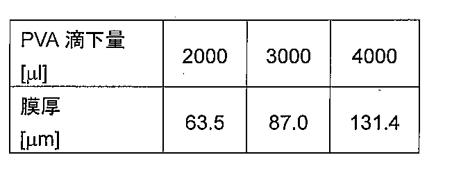
- Table 2 shows changes in the film thickness in the range when the amount of the PVA solution dropped is changed.
- a PVA sheet having a size of 20 mm ⁇ 30 mm in the vicinity of the center of a 40 mm ⁇ 50 mm glass substrate obtained by a predetermined amount dropping method was used.
- Example 2 Evaluation of mechanical properties of PVA sheet (2-1) Tensile test A tensile test was performed to evaluate the mechanical properties of the PVA sheet. Two types of force gauges (manufactured by IMADA, ZTA-500N) (manufactured by IMADA, ZTA-5N) and a measuring stand (manufactured by IMADA, MX2-500N-FA) were used as a testing machine used for the tensile test. In order to measure a film-shaped test piece, a roller chuck type jig (manufactured by IMADA, GC-100) was used as a jig.
- the force gauge was moved upward at a pulling speed of 10 mm / min to pull the PVA sheet.
- the length for holding the test piece was about 10 mm.
- seat at that time and the moving distance of a force gauge were measured, and the value of the load for extending the elongation amount of a PVA sheet
- seat was obtained.
- a stress strain diagram was created from the value of the strain obtained by dividing the amount of elongation of the PVA sheet by the length of the test piece and the value of the stress obtained by dividing the load applied to the PVA sheet by the cross-sectional area of the PVA sheet.
- FIG. 4 shows a stress strain diagram with a film thickness of 63.5 ⁇ m.
- the Young's modulus was obtained by taking the slope of the straight part of the small strain part of the obtained stress-strain diagram.
- the Young's modulus of the PVA sheet having a film thickness of 63.5 ⁇ m was determined to be 48.9 MPa.
- the Young's modulus of a PVA sheet having a thickness of 87.0 ⁇ m was determined to be 28.8 MPa
- the Young's modulus of a PVA sheet having a thickness of 131.4 ⁇ m was determined to be 30.7 MPa.
- the difference in Young's modulus depending on the film thickness is considered to be because the amount of water evaporated during the drying process is different and the moisture content of the resulting PVA sheets is different.
- FIG. 5 shows the results of examining the change in film thickness due to dissolution of PVA. From this result, an average dissolution rate of 0.18 ⁇ m / s was obtained.
- a two-layer structure sheet of nanosheet and support layer was used.
- a nanosheet was formed on a glass substrate, and a PVA sheet serving as a support layer was produced thereon by a predetermined amount dropping method.
- the nanosheet was prepared by dissolving polylactic acid (manufactured by Polyscience) at 10 mg / ml in dichloromethane (manufactured by Kanto Chemical Co., Ltd.), and dispersing magnetic nanoparticles having a particle shape of 10 nm (manufactured by Ferrotec) at 15 mg / ml. A solution was prepared.
- the obtained solution was dropped on a glass substrate and spin coating was performed to form a nanosheet.
- the nanosheet was prepared to have a thickness of about 200 nm and a size of 5 mm ⁇ 5 mm by setting the spin coat rotation speed to 3000 rpm and the rotation time to 20 seconds.
- Attaching the two-layer structure sheet to the PVA sheet to be the stretchable layer involves dissolving the surface of the PVA sheet of the stretchable layer with 70% ethanol, and then sticking the nanosheet using the adhesive strength of PVA.
- a multilayer structure of nanosheet / support layer was formed.
- the cylindrical shape was automatically formed by cutting out two sides parallel to the pulling direction and cutting one side perpendicular to the pulling direction in the overlapping part. Finally, the remaining one side was cut out to obtain a cylindrical multilayer structure sheet. For cutting, a scalpel was used to clean the edges.
- FIG. 8 shows a cylindrical multilayer structure sheet produced as described above using a PVA sheet having a film thickness of 63.5 ⁇ m for the support layer and the stretch layer, and applying a tensile strain of 0.3 to the stretch layer. At this time, the radius of curvature was 0.92 mm.
- Example 4 Evaluation of cylindrical shape control of multilayer structure sheet
- the radius of curvature obtained by winding the multilayer structure sheet can theoretically be determined as follows. Note that the thickness of the nanosheet is neglected because it is very thin compared to the support layer and the stretchable layer, and the radius of curvature of the support layer and the stretchable layer is sufficiently large compared to the distance between the neutral axes of the two layers. Are assumed to be equal.
- the radius of curvature r obtained by winding the multilayer structure sheet can be expressed by the following formula 1 (S. Timoshenko, “Analysis of Bi-Metal Thermostats,” J. Opt. Soc. Am. Rev. Sci.Instrument, vol.11, pp.233-255, 1925.).
- t 1 and t 2 indicate the film thicknesses of the support layer and the stretchable layer, respectively, E 1 and E 2 indicate the Young's modulus of the support layer and the Young's modulus when tensile strain is applied to the stretchable layer, and ⁇ 'Indicates the recovery strain of the stretchable layer to which a tensile strain ⁇ is added.
- Formula 1 can be expressed by Formula 2 below.
- ⁇ ( ⁇ ) is a stress applied to the material when a tensile strain ⁇ is applied, and can be obtained by measuring a stress strain diagram of the material.
- the radius of curvature r of the multilayer structure sheet can be determined based on the thickness t of the support layer and the stretch layer and the applied tensile strain ⁇ .
- the supporting layer and the stretchable layer were PVA sheets having a film thickness of 63.5 ⁇ m, the change in the radius of curvature r obtained when the applied tensile strain ⁇ was changed was examined.
- FIG. 9 shows a comparison result between the actually measured value of the curvature radius r and the theoretical value of the above equation 2.
- the Young's modulus E of the PVA sheet was 48.9 MPa from the actual measurement of the stress strain diagram.
- FIG. 10 shows a comparison result between the actually measured value of the curvature radius r and the theoretical value of the above equation 2.
- the Young's modulus E of the PVA sheet was 28.8 MPa when the film thickness of the PVA sheet was 87.0 ⁇ m and 30.7 MPa when the film thickness of the PVA sheet was 131.4 ⁇ m.
- the radius of curvature r of the multilayer structure sheet can be determined based on the thickness t of the support layer and the stretch layer and the applied tensile strain ⁇ .
- Example 5 Evaluation of planar shape control of multilayer structure sheet Development evaluation of the multilayer structure sheet (FIG. 8) obtained in Example 3 to a planar shape was performed.
- the multilayer structure sheet was placed on the bottom of a plastic petri dish filled with pure water at room temperature, PVA was dissolved, and the state of shape change was observed from above.
- the evaluation was performed based on the development ratio ⁇ of the ratio S / S 0 of the area S 0 of the original nanosheet (5 mm ⁇ 5 mm) and the area S of the nanosheet when observed from above.
Landscapes
- Materials For Medical Uses (AREA)
- Laminated Bodies (AREA)
Abstract
本発明は、平面形状を維持することが可能なナノシート及びその製造方法を提供することを目的とする。 ナノシート層及び伸縮層を含み、捲回構造を備える多層構造シート、ならびにその製造方法。
Description
本発明は、ナノシート層及び伸縮層を含み、捲回構造を備える多層構造シート、ならびにその製造方法に関する。
高分子超薄膜(以下、「ナノシート」と記載する)とはポリ乳酸等の高分子からなる数十~数百nmの厚さを持つシートのことであり、その薄さと柔軟性から、皮膚や臓器の表面形状に追従し、接着剤なしでもファンデルワールス力や表面張力によって貼付することができる。
この特徴からナノシートは、創部保護材料として患部や切開創へ貼付して用いられている(非特許文献1,2)。また近年においては、ナノシートを、内視鏡手術において創部保護材料として用いること、また生体組織(網膜下等)への細胞移植手術の移植基材として用いること等、生体内の狭小な環境下での利用が開発・検討されている(非特許文献3-5)。
一方、ナノシートは薄く、柔軟であることから、液中において折れ曲がる等して変形した場合、平面形状へ自力で回復することはできない。そのため、ナノシートの変形を抑え、平面形状を維持して、目的の部位に貼付することは容易ではない。さらに目的の部位が生体内の狭小な環境である場合には、ナノシートを直接操作することはできないことから、平面形状を維持しながら貼付することはより困難となる。
したがって、当該分野においてはナノシートの平面形状を維持/制御しながら、簡便に、目的の部位に貼付することを可能とする新たな手段が切望されている。
Fujie et al,Advanced Functional Materials,vol.19,pp.2560-2568,2009.
Okamura et al,Advanced Materials,vol.21,pp.4388-4392,2009.
Taccola et al,Langmuir,vol.27,pp.5589-5595,2011.
Mattoli et al,Procedia Chemistry,vol.1,pp.28-31,2009.
Fujie et al,Advanced Material,vol.26,pp.1699-1705,2014.
本発明は、平面形状を維持することが可能なナノシート及びその製造方法を提供することを目的とする。
本発明者らは、ナノシートは液中において粘性抵抗や浮力を受けており、これらの力が、液中にて変形状態にあるナノシートが平面形状に戻ろうとする復元力(すなわち、曲げモーメント)とつりあうため、一度変形したナノシートは自力で平面形状に回復できないことを見出した。
そこで、本発明者らはナノシートの曲げモーメントを大きくし、ナノシートの平面形状を維持することを検討した結果、大きな断面2次モーメントを持つ層(シート)をナノシートと組み合わせることによって、ナノシート自体の膜厚を厚くすることなく、ナノシートの曲げモーメントを大きくすることができ、これによって液中にて平面形状を維持できることを見出した。
一方、別の層と組み合わされたナノシートは、薄さと柔軟性が失われるため、ナノシート送達に利用されている細管(例えば、シリンジやカテーテル等)への収納が困難となるが、これは、当該ナノシートを、捲回構造体とすることによって解決できることを見出した。本発明者らはナノシートと別の層とを捲回構造体とする簡便な手法を検討した結果、ひずみを生じ内部応力が付与された別の層にナノシートを接着・積層して多層構造体とし、その後ひずみを回復させ各層の応力差を利用することによって多層構造体を自発的に捲回させることができ、目的の捲回構造体を形成できることを見出した。
本発明は、これらの知見に基づくものであり、以下の特徴を有する。
[1] ナノシート層及び伸縮層を含み、捲回構造を備える多層構造シートの製造方法であって、
(i)ナノシート層を、ひずみを生じさせ内部応力を付与した伸縮層に積層し、多層構造を形成する工程、
(ii)次いで、該多層構造における該伸縮層の該ひずみを回復させ、それによって該多層構造を捲回する工程を含む、
上記方法。
[2] 多層構造シートが支持層をさらに含み、工程(i)において、支持層/ナノシート層/伸縮層の順で積層するか、又は、ナノシート層/支持層/伸縮層の順で積層する、[1]の方法。
[3] 工程(i)において、引張力を加えて引張ひずみを生じさせ内部応力が付与された伸縮層に支持層(存在する場合)及びナノシート層を積層する、[1]又は[2]の方法。
[4] 工程(ii)において、多層構造を伸縮層に引張力が加えられた環境より切り取り、切り取られた多層構造における伸縮層の引張ひずみを回復させ、それによって該切り取られた多層構造を伸縮層と支持層(存在する場合)及び/又はナノシート層との間の内部応力の差に基づいて捲回する、[3]の方法。
[5] ナノシート層及び伸縮層を含み、捲回構造を備える、多層構造シート。
[6] 支持層をさらに含み、支持層/ナノシート層/伸縮層の順で積層されているか、又は、ナノシート層/支持層/伸縮層の順で積層されている、[5]の多層構造シート。
[7] ナノシート層が500nm未満の厚みを有する、[5]又は[6]の多層構造シート。
[8] 支持層(存在する場合)及び/又は伸縮層が250μm未満の厚みを有する、[5]~[7]のいずれかの多層構造シート。
[9] 支持層(存在する場合)及び伸縮層が水溶性高分子からなる、[5]~[8]のいずれかの多層構造シート。
[10] 支持層(存在する場合)及び伸縮層がポリビニルアルコールからなる、[5]~[9]のいずれかの多層構造シート。
[1] ナノシート層及び伸縮層を含み、捲回構造を備える多層構造シートの製造方法であって、
(i)ナノシート層を、ひずみを生じさせ内部応力を付与した伸縮層に積層し、多層構造を形成する工程、
(ii)次いで、該多層構造における該伸縮層の該ひずみを回復させ、それによって該多層構造を捲回する工程を含む、
上記方法。
[2] 多層構造シートが支持層をさらに含み、工程(i)において、支持層/ナノシート層/伸縮層の順で積層するか、又は、ナノシート層/支持層/伸縮層の順で積層する、[1]の方法。
[3] 工程(i)において、引張力を加えて引張ひずみを生じさせ内部応力が付与された伸縮層に支持層(存在する場合)及びナノシート層を積層する、[1]又は[2]の方法。
[4] 工程(ii)において、多層構造を伸縮層に引張力が加えられた環境より切り取り、切り取られた多層構造における伸縮層の引張ひずみを回復させ、それによって該切り取られた多層構造を伸縮層と支持層(存在する場合)及び/又はナノシート層との間の内部応力の差に基づいて捲回する、[3]の方法。
[5] ナノシート層及び伸縮層を含み、捲回構造を備える、多層構造シート。
[6] 支持層をさらに含み、支持層/ナノシート層/伸縮層の順で積層されているか、又は、ナノシート層/支持層/伸縮層の順で積層されている、[5]の多層構造シート。
[7] ナノシート層が500nm未満の厚みを有する、[5]又は[6]の多層構造シート。
[8] 支持層(存在する場合)及び/又は伸縮層が250μm未満の厚みを有する、[5]~[7]のいずれかの多層構造シート。
[9] 支持層(存在する場合)及び伸縮層が水溶性高分子からなる、[5]~[8]のいずれかの多層構造シート。
[10] 支持層(存在する場合)及び伸縮層がポリビニルアルコールからなる、[5]~[9]のいずれかの多層構造シート。
本明細書は本願の優先権の基礎となる日本国特許出願番号2015-043990号の開示内容を包含する。
本発明によれば、捲回構造を有し、かつ、ナノシートを自力で/非接触様式にて平面形状へと展開することが可能である、ナノシートを含む多層構造シートを提供することができる。
また、本発明によれば、当該多層構造シートを簡便に製造することができる。
(1)ナノシート層
本発明において「ナノシート層」とは、ナノシートを含むか、当該ナノシートからなる層を意味する。「ナノシート」とは、500nm未満、好ましくはおよそ20nm~300nm、より好ましくはおよそ50nm~200nm程度の厚みを有するシートを意味する。
本発明において「ナノシート層」とは、ナノシートを含むか、当該ナノシートからなる層を意味する。「ナノシート」とは、500nm未満、好ましくはおよそ20nm~300nm、より好ましくはおよそ50nm~200nm程度の厚みを有するシートを意味する。
ナノシートは高分子からなり、例えばポリ乳酸、ポリグリコール酸、ポリヒドロキシ酪酸、ポリカプロラクトン、ポリブチレンサクシネート、ポリジオキサノン、ポリジメチルシロキサン、ポリメチルメタクリレート、ポリスチレン、ポリ酢酸ビニル、ポリ(3,4-エチレンジオキシチオフェン)、タンパク質(コラーゲン、ゼラチン、ラミニン、ファイブロネクチン、エラスチン)、多糖類(キトサン、アルギン酸、ヒアルロン酸、コンドロイチン硫酸、セルロース)、核酸(DNA,RNA)及びそれらの共重合体等より選択される適当なものを利用して作製することができる。好ましくはナノシートは生体分解性高分子からなる。
ナノシート層の作製方法は特に限定されることなく、従来公知の一般的な手法(例えば、スピンコート法)を用いて行うことができる。スピンコート法においては、高分子又は当該高分子の構成要素(例えば、高分子の構成要素であるところのモノマー等)(以下、「高分子等」と記載する。)を適当な溶媒(例えば、ジクロロメタン、クロロホルム、アセトン、酢酸エチル等)中に1mg/mL~100mg/mL、好ましくは5mg/mL~40mg/mLの濃度で溶解し、この高分子等の溶液を基板(例えば、ポリジメチルシロキサン(PDMS)、金属、シリコン、ガラス等)上に滴下し、スピンコーターを用いて塗布し、その後乾燥させる。スピンコーターの回転速度、回転時間を調節することにより、基板表面上に塗布される高分子等の厚みを調節することができ、最終生成物であるナノシート層の厚みを調節することができる。基板上に形成されたナノシート層は、任意の手段により基板上より剥がすことができる。ナノシート層はその薄さからピンセット等を用いて基板上より物理的に剥がすことは容易ではないが、例えばイソプロピルアルコール(IPA)に浸漬することによって、基板とナノシート層との間にIPAが入り込み、自発的に基板上より剥がすことができる。
ナノシート層の形状や大きさは目的に応じて適宜選択することができ、例えばその直径又は最も長い対角線の長さがおよそ10μm~50mm、好ましくはおよそ100μm~20mm、さらに好ましくはおよそ1mm~10mm程度とすることができる(これらに限定はされない)。なお、「形状や大きさ」とは、厚み方向と垂直に交わる面の形状や大きさを意味する。
ナノシート層には、磁性体からなるナノ粒子を担持させることができる。磁性体からなるナノ粒子をナノシート層に担持させることによって、当該ナノシート層を磁力を用いて移動/集合させることができ操作性を高めることができる。磁性体からなるナノ粒子は1nm~500nm、好ましくは1nm~50nm程度の粒子径を有する。磁性体からなるナノ粒子は、上記生体適合性高分子等の溶液中に含め、生体適合性高分子等と共に基板表面上に塗布することにより最終生成物であるナノシート層に担持させることができる。磁性体からなるナノ粒子は生体適合性高分子等の溶液中に0.1mg/mL~50mg/mL、好ましくは1mg/mL~25mg/mLの濃度で含めることができる。
また、ナノシート層には、機能性物質を担持させることができる。「機能性物質」とは、細胞の増殖、分化、生理活性等を制御する機能を有する物質(例えば、タンパク質、ポリペプチド、化合物等)やナノシート層の可視化を可能にする物質を意味する。このような機能性物質としては、成長/増殖因子(例えば、線維芽細胞増殖因子(FGF)、上皮成長因子(EGF)、骨形成タンパク質(BMP)、神経成長因子(NGF)、脳由来神経栄養因子(BDNF)等)、眼圧降下剤、神経保護剤、抗生物質、抗がん剤、可視化プローブ(造影剤、ナノ粒子、蛍光色素等)が挙げられる。機能性物質をナノシート層に担持させることによって、ナノシート層に機能性物質に由来する細胞の増殖、分化、生理活性等を制御する等の機能を付与することができる。機能性物質はナノシート層に対して化学的又は物理的手法を用いて結合させることができる。化学的手法としては、官能基を介した化学的結合が挙げられ、例えば生体適合性高分子等を予め適当な官能基(例えばアミノ基、カルボキシル基、ヒドロキシル基、アルデヒド基等)で修飾しておき、得られたナノシート層に対して当該導入した官能基を介して機能性物質を結合させることができる。物理的手法としては、ナノシート層と機能性物質との間の静電的相互作用、疎水性相互作用、水素結合、分子間力などによる結合が挙げられる。
また、ナノシート層の表面は細胞の接着及び増殖を促進する細胞外基質によりコーティングすることができる。「細胞外基質」としては、例えば、I型コラーゲン、IV型コラーゲン、フィブロネクチン、ポリ-D-リジン(PDL)、ラミニン、ポリ-L-オルニチン/ラミニン(PLO/LM)等が挙げられる。ナノシートの表面を細胞外基質によりコーティングすることによって、当該ナノシート層の表面は細胞の接着及び増殖を促進するための足場として利用することができる。
本発明の多層構造シートには、異なる高分子からなるナノシート層、形状や大きさの異なるナノシート層、異なる物質(磁性体、機能性物質、細胞外基質等)を担持したナノシート層等、特性や機能が異なるナノシート層を複数積層して含めることができる。
なお、本明細書中、ナノシートからなるナノシート層のことを単に、ナノシートと記載する場合がある。
(2)支持層
本発明において「支持層」とは、250μm未満、好ましくはおよそ20μm~150μm、より好ましくはおよそ50μm~100μm程度の厚みを有する高分子からなるシートを含むか、当該シートからなる層を意味する。支持層のシートに利用可能な高分子としては、上記「(1)ナノシート層」に記載のものを利用することができる。また、例えば、水溶性高分子を利用することができる。「水溶性高分子」としては、水に可溶であるものであればよい。好ましくはさらに生体適合性を有するものが挙げられる。このような水溶性高分子としては例えば、ポリビニルアルコール(PVA)もしくはその誘導体、ポリイソプロピルアクリルアミドもしくはその誘導体、ポリエーテルもしくはその誘導体、多糖類、高分子電解質もしくはその塩等が挙げられる。
本発明において「支持層」とは、250μm未満、好ましくはおよそ20μm~150μm、より好ましくはおよそ50μm~100μm程度の厚みを有する高分子からなるシートを含むか、当該シートからなる層を意味する。支持層のシートに利用可能な高分子としては、上記「(1)ナノシート層」に記載のものを利用することができる。また、例えば、水溶性高分子を利用することができる。「水溶性高分子」としては、水に可溶であるものであればよい。好ましくはさらに生体適合性を有するものが挙げられる。このような水溶性高分子としては例えば、ポリビニルアルコール(PVA)もしくはその誘導体、ポリイソプロピルアクリルアミドもしくはその誘導体、ポリエーテルもしくはその誘導体、多糖類、高分子電解質もしくはその塩等が挙げられる。
支持層の作製方法は特に限定されることなく、水溶性高分子からなるシートの作製において従来公知の一般的な手法(例えば、スピンコート法、キャスト法等)を用いて行うことができる。スピンコート法においては、上記ナノシートの作製と同様に、高分子を適当な溶媒(例えば、ジクロロメタン、クロロホルム、アセトン、酢酸エチル、水等)中に1mg/mL~100mg/mL、好ましくは5mg/mL~40mg/mLの濃度で溶解し、この高分子の溶液を基板(例えば、ポリジメチルシロキサン(PDMS)、金属、シリコン、ガラス等)上に滴下し、スピンコーターを用いて塗布し、その後乾燥させる。スピンコーターの回転速度、回転時間を調節することにより、基板表面上に塗布される高分子の厚みを調節することができ、最終生成物である支持層の厚みを調節することができる。キャスト法においては、上記したように高分子を適当な溶媒中に溶解し、この高分子の溶液を基板上に滴下又は噴霧して塗布し、その後乾燥させる。滴下又は噴霧する高分子の溶液の量を調節することにより、基板表面上に塗布される高分子の厚みを調節することができ、最終生成物である支持層の厚みを調節することができる。
基板上に形成された支持層は任意の手段により基板上より剥がすことができ、ピンセット等を用いて基板上より物理的に剥がしてもよいし、例えばイソプロピルアルコール(IPA)に浸漬することによって、自発的に基板上より剥がしてもよい。
支持層はナノシート層と組み合わされて、ナノシート層の曲げモーメントを大きくすることができればよく、その形状や大きさは特に限定されることなく、平面形状に展開された状態のナノシート層の全体又はその一部(例えば、ナノシート層全体の面積の20%以上、30%以上、40%以上、50%以上、60%以上、70%以上、80%以上、90%以上、もしくはそれ以上)を支持(裏打ち)することが可能な形状や大きさであればよい。したがって、ナノシート層と組み合わされて、ナノシート層の曲げモーメントを大きくすることができる限り、支持層はナノシート層と同じ形状や大きさであってもよいし、異なる形状や大きさであってもよい。
支持層はナノシート層の平面形状を維持するために、以下の式で表される曲げ変性をしたときの反力曲げモーメントの値が、ナノシート層について得られる当該値よりも大きいことを特徴とする。
曲げ変性をしたときの反力曲げモーメント=EI/ρ
(式中、E:ヤング率,I:断面2次モーメント,ρ:曲率半径を表す)
曲げ変性をしたときの反力曲げモーメント=EI/ρ
(式中、E:ヤング率,I:断面2次モーメント,ρ:曲率半径を表す)
ナノシート層の操作を容易にするために、ナノシート層と支持層とは予め2層構造体として形成されてもよい。すなわち、上記のとおり基板上にまずナノシート層を形成し、その後そのナノシート層上に、上記のとおり支持層を形成するか、あるいは上記のとおり基板上にまず支持層を形成し、その後その支持層上に、上記のとおりナノシート層を形成する。形成された2層構造体は、ピンセット等を用いて基板上より物理的に剥がしてもよいし、例えばイソプロピルアルコール(IPA)に浸漬することによって、基板上より自発的に剥がしてもよい。
(3)伸縮層
本発明において「伸縮層」とは、250μm未満、好ましくはおよそ20μm~150μm、より好ましくはおよそ50μm~100μm程度の厚みを有する高分子からなるシートを含むか、当該シートからなる層を意味する。伸縮層に利用可能な「高分子」としては、上記支持層にて利用可能な「高分子」として定義したものを挙げることができる。
本発明において「伸縮層」とは、250μm未満、好ましくはおよそ20μm~150μm、より好ましくはおよそ50μm~100μm程度の厚みを有する高分子からなるシートを含むか、当該シートからなる層を意味する。伸縮層に利用可能な「高分子」としては、上記支持層にて利用可能な「高分子」として定義したものを挙げることができる。
伸縮層の作製方法は特に限定されることなく、高分子からなるシートの作製において従来公知の一般的な手法(例えば、スピンコート法、キャスト法等)を用いて行うことができる。スピンコート法及びキャスト法は、上記支持層の作製方法と同様に実施することができる。基板上に形成された支持層は任意の手段により基板上より剥がすことができ、ピンセット等を用いて基板上より物理的に剥がしてもよいし、例えばイソプロピルアルコール(IPA)に浸漬することによって、自発的に基板上より剥がしてもよい。
伸縮層と支持層とは、同じ高分子より構成されていてもよいし、異なる高分子より構成されていてもよく、また伸縮層と支持層の厚みは同じ又は同程度であってもよいし、異なっていてもよい。好ましくは、伸縮層と支持層とは同じ高分子より構成され、かつ同じ又は同程度の厚みを有する。「同程度」とは、一層の厚みが他方の層の厚みの2倍未満、又は1.5倍未満であることを意味する。伸縮層及び支持層が水溶性高分子である場合、これらの層は水への溶解に際して、同時に膨潤・伸長を生じ得、この膨潤・伸長がナノシート層の平面形状への展開に影響を及ぼし得る。伸縮層と支持層とを、同じ水溶性高分子より構成し、かつ同じ又は同程度の厚みを有するものとすることにより、当該影響を小さくすることができる。
伸縮層の形状や大きさは特に限定されることなく、ひずみを生じさせることが可能であり、かつひずみを生じさせ内部応力が付与された状態において、支持層及び/又はナノシート層の全体又はその一部(例えば、全体の面積の20%以上、30%以上、40%以上、50%以上、60%以上、70%以上、80%以上、90%以上、もしくはそれ以上)を支持(裏打ち)することが可能な形状や大きさであればよい。
伸縮層について、上記の式で表される曲げ変性をしたときの反力曲げモーメントの値が、ナノシート層について得られる当該値よりも大きい場合には、伸縮層はナノシート層の平面形状の維持に関与することができる。この場合には、伸縮層が支持層の機能も果たすことから、本発明の多層構造シートにおいて支持層はあってもよいし、なくてもよい。
(4)水溶性犠牲層
ナノシート層、支持層、及び/又は伸縮層には、液中(例えば、体液中)に可溶な水溶性犠牲層を含めることができる。水溶性犠牲層を含めることにより、多層構造シートを液中に置いた場合に当該水溶性犠牲層が溶解し、各層を隣接する層より剥離するために利用することができる。例えば、多層構造シートにおいて、ナノシート層と支持層及び/又は伸縮層との間に配置されるように、各層又はいずれかの層に水溶性犠牲層を含めることにより、多層構造シートを液中に置いた場合に当該水溶性犠牲層が溶解し、ナノシートより支持層及び/又は伸縮層を剥離することができる。また、ナノシート層に水溶性犠牲層を含め、ナノシートと水溶性犠牲層とを予め2層構造体として形成することによって、ナノシート層の操作性を高めることができる。
ナノシート層、支持層、及び/又は伸縮層には、液中(例えば、体液中)に可溶な水溶性犠牲層を含めることができる。水溶性犠牲層を含めることにより、多層構造シートを液中に置いた場合に当該水溶性犠牲層が溶解し、各層を隣接する層より剥離するために利用することができる。例えば、多層構造シートにおいて、ナノシート層と支持層及び/又は伸縮層との間に配置されるように、各層又はいずれかの層に水溶性犠牲層を含めることにより、多層構造シートを液中に置いた場合に当該水溶性犠牲層が溶解し、ナノシートより支持層及び/又は伸縮層を剥離することができる。また、ナノシート層に水溶性犠牲層を含め、ナノシートと水溶性犠牲層とを予め2層構造体として形成することによって、ナノシート層の操作性を高めることができる。
水溶性犠牲層は上記「水溶性高分子」を用いて作製することができ、高分子からなるシートの作製において従来公知の一般的な手法(例えば、スピンコート法、キャスト法等)を利用して設けることができる。すなわち、上記のとおり基板上に形成されたナノシート層、支持層又は伸縮層上に、適当な溶媒(例えば、水)に溶解した水溶性高分子を塗布、滴下又は噴霧して乾燥させることにより、各層の上に水溶性犠牲層を形成してもよいし、ならびに/あるいは基板上にまず水溶性犠牲層を同様に形成し、その後その水溶性犠牲層上に、上記のとおり各層を形成してもよい。
(5)多層構造シートの製造方法
多層構造シートの製造は、
(i)ひずみを生じさせ内部応力を付与した伸縮層に、ナノシート層又はナノシート層と支持層を積層し、多層構造を形成する工程;ならびに
(ii)多層構造における伸縮層のひずみを回復させ、それによって前記多層構造を自発的に捲回させる工程、を含む。
多層構造シートの製造は、
(i)ひずみを生じさせ内部応力を付与した伸縮層に、ナノシート層又はナノシート層と支持層を積層し、多層構造を形成する工程;ならびに
(ii)多層構造における伸縮層のひずみを回復させ、それによって前記多層構造を自発的に捲回させる工程、を含む。
ここで「ひずみ」とは、伸縮層に内部応力を付与できるものであればよく、圧縮ひずみや引張ひずみを挙げることができるが、好ましくは引張ひずみである。以下、引張ひずみを利用した、ナノシート層、支持層、及び伸縮層を含む多層構造シートの製造方法について述べるが、本発明は当該手法に限定されるものではない。
本発明の製造方法の模式図を図1に示す。
工程(i)において、ナノシート層及び支持層を積層するに際して、伸縮層には予め、引張ひずみを生じさせ引張の内部応力が付与される(図1(a))。
引張ひずみは、伸縮層の対向する両端の一方又は両方を、対向する方向とは反対方向に引張ることによって生じさせることができる。引張ひずみは一般的に以下の式で表すことができる:引張ひずみ=力を加えることによって変形した(伸びた)長さ/力を加える前の元の長さ。
伸縮層にどの程度の引張ひずみを生じさせるかは、支持層や伸縮層を構成する高分子の種類や、これらの層の厚み、ならびに最終的に得られる多層構造シートの捲回構造において所望される曲率半径に基づいて、適宜決定することができる。例えば、支持層や伸縮層を構成する高分子の種類や、これらの層の厚みを一定にした条件下にて、引張ひずみを変化させることによって、所望される曲率半径を有する多層構造シートが得られる引張ひずみの大きさを見出すことができる。あるいは、支持層や伸縮層を構成する高分子の種類や、これらの層の厚みを変化させ、一定の引張ひずみの条件下にて、所望される曲率半径を有する多層構造シートが得られる条件を見出すことができる。あるいは、下記実施例に詳述するとおり、支持層や伸縮層の厚みやヤング率、及び応力ひずみ線図を計測した上で、所望される曲率半径を得るために必要とされる引張ひずみを理論値より導き出すことができる。例えば、支持層と伸縮層とが共にPVAよりなり、その厚みが共におよそ50~150μmである場合、引張ひずみを0.1~0.4とすることによって、曲率半径がおよそ0.9~1.5mm程度の捲回構造を有する多層構造シートを得ることができる。
引張の内部応力が付与された伸縮層へのナノシート層及び支持層の積層は、伸縮層/ナノシート層/支持層の順でなされてもよいし、あるいは伸縮層/支持層/ナノシート層の順でなされてもよい。伸縮層及び支持層が水溶性高分子である場合、これらの層の水への溶解に際して生じる膨潤・伸長のナノシート層への影響は、伸縮層/支持層/ナノシート層の順で積層するよりも、伸縮層/ナノシート層/支持層の順で積層することによって小さくすることができる。
各層の積層は、伸縮層及び/又は支持層の接着面を一部溶解して粘着力を付与し、これにより隣接する層と接着させることにより行うことができる。例えば、伸縮層及び/又は支持層にPVAを用いる場合には、その表面に70%エタノールを噴霧又は塗布することによって当該面に、隣接層と接着するための粘着力を付与することができる。
工程(ii)において、多層構造における伸縮層のひずみの回復は、多層構造における伸縮層に加えられた引張力を除去することにより行うことができる。引張力の除去は多層構造における伸縮層における引張ひずみを回復できればよく特に限定はされないが、例えば、上記引張り方向とは反対方向に伸縮層の対向する両端の一方又は両方を移動させることによって行っても良いし、あるいは、形成された多層構造を伸縮層に引張力が加えられた環境より切り取ることにより行うことができる。所望の形状や大きさに多層構造シートを調整できることから、切り取る手段を用いることが好ましい。多層構造シートにおいて予め引張力により内部応力が付与されていた伸縮層は引張力が除去されることによりひずみを回復させ縮む一方で、同様の内部応力が付与されていないナノシート層及び支持層は伸縮層と共に縮むことはない。本工程においては、多層構造シートにおけるこの伸縮層とナノシート層及び支持層との間の応力差を利用して、多層構造シートを自発的に捲回させることができる(図1(b))。ここで「自発的に捲回」とは、ナノシート層及び支持層と伸縮層との間の応力の差に基づいて捲回することを意味し、多層構造シートに外部より力を加えて捲回する(例えば、多層構造シートを機械的に回転させる)ことを意味しない。
切り取るに際しては、切り取られた多層構造シートが一方向へ自発的に捲回するように、最終的に切り離される多層構造シートの部分(点)は、引張り方向と垂直な辺上にあるか、又は伸縮層の表面に想定される引張り方向と垂直な線と多層構造シートの接点とすることが好ましい。多層構造シートの切り取りは、任意の手段で行うことができ、はさみ、カッターナイフ、ナイフ、メス(スカルペル)、レーザー等を利用することができる。切り取られる形状や大きさは、多層構造を含む限り、適宜決定することができる。
(6)多層構造シート
本発明の多層構造シートは、上記ナノシート層及び伸縮層を含み、かつ捲回構造を有する。多層構造シートが支持層を含む場合には、ナノシート層、支持層及び伸縮層は、伸縮層/ナノシート層/支持層の順で積層されていてもよいし、あるいは伸縮層/支持層/ナノシート層の順で積層されていてもよい。多層構造シートにおける各層の形状や大きさは、上記のとおり、それぞれ異なっていても良いし、同一であってもよい。
本発明の多層構造シートは、上記ナノシート層及び伸縮層を含み、かつ捲回構造を有する。多層構造シートが支持層を含む場合には、ナノシート層、支持層及び伸縮層は、伸縮層/ナノシート層/支持層の順で積層されていてもよいし、あるいは伸縮層/支持層/ナノシート層の順で積層されていてもよい。多層構造シートにおける各層の形状や大きさは、上記のとおり、それぞれ異なっていても良いし、同一であってもよい。
本発明の多層構造シートは、液中(例えば、体液中)に放出されると、捲回構造より自力で又は非接触様式にて平面形状へと展開することができる。「自力で又は非接触様式」とは、多層構造シートを平面形状へ展開するために、人為的な操作(例えば、ピンセット等を用いて物理的に力を加えること)を必要としないことを意味する。平面形状に展開されたナノシートは、支持層及び/又は伸縮層に支持(裏打ち)されて曲げモーメントが大きくなることから、液中にて平面形状を維持することができる。
本発明の多層構造シートは捲回構造を有し、その大きさに応じて適当な内径を有する細管で吸引することができ、また当該細管より放出することができる。これにより本発明の多層構造シートは、細管を用いて生体内の狭小な環境へ投与・送達することができる。「捲回構造」としては、円筒形、円錐形、円錐台形等が挙げられるが、特に限定はされない。「細管」としては例えば、注射針やカテーテル等が挙げられる。「細管」のサイズ(ゲージ)や長さは、多層構造シートの大きさや、多層構造シートを導入する部位等の要因に応じて適宜選択することができる。細管を利用することによって、多層構造シートを対象に低侵襲的に送達することができる。
液中(例えば、体液中)にて、ナノシート層よりその他の層が除去され、最終的にナノシート層を目的の部位に貼付することができる。当該除去は、支持層や伸縮層を水溶性高分子からなるものとすることによって液中にて溶解させることによって行ってもよいし、ナノシート層とその他の層との間に水溶性高分子からなる層(水溶性犠牲層)を設け、液中にて当該犠牲層を溶解させその他の層を剥離することによって行ってよい。また、ナノシート層が生体分解性高分子からなる場合、貼付されたナノシート層も最終的には生体内で分解吸収される。
次に実施例を挙げ、本発明をさらに詳しく説明するが、本発明はこれらに限定されるものではない。
実施例1:PVAシートの作製
(1-1)スピンコート法
純水に10wt%の濃度でPVAを溶解させたPVA溶液を調製し、これをガラス基板上に滴下して10秒間、スピンコートを行った。スピンコートの回転時間を10秒間としたときの、回転数と得られたPVAシートの膜厚を表1に示す。
(1-1)スピンコート法
純水に10wt%の濃度でPVAを溶解させたPVA溶液を調製し、これをガラス基板上に滴下して10秒間、スピンコートを行った。スピンコートの回転時間を10秒間としたときの、回転数と得られたPVAシートの膜厚を表1に示す。

スピンコートによって得られたPVAシートは、PVAシートが成膜されたガラス基板をIPA中に浸すことで、ガラス基板とガラス基板の間にIPAが入り込み、自発的に剥がすことができた。
(1-2)一定量滴下法
純水に10wt%の濃度でPVAを溶解させたPVA溶液を調製し、これを40mm×50mmのガラス基板上に、2000μl、3000μl、及び4000μlの量でそれぞれ滴下し、40℃にて乾燥させPVAシートを得た。乾燥時間は、2000μlでは60分間、3000μlでは90分間、4000μlでは120分間とした。
純水に10wt%の濃度でPVAを溶解させたPVA溶液を調製し、これを40mm×50mmのガラス基板上に、2000μl、3000μl、及び4000μlの量でそれぞれ滴下し、40℃にて乾燥させPVAシートを得た。乾燥時間は、2000μlでは60分間、3000μlでは90分間、4000μlでは120分間とした。
一定量滴下法によって得られたPVAシートは表面張力の影響によりガラス基板の端付近が中心付近より厚く成膜されることが確認された。そのため、PVAシートの膜厚均一性評価を以下のとおり行った。
図2のように、得られたPVAシートの2箇所(切断面1と切断面2)を切り取り、A部分とC部分のPVAシートをガラス基板から剥がした後、切断面1と切断面2において得られた段差を、レーザー段差計(KEYENCE VK-9510)を用いて計測した。その際、図2の切断面1の点a1から点g1と、切断面2の点a2から点b2の計測を行なった。
滴下量を4000μlとしたときの切断面1、切断面2の計測点における膜厚の計測結果を図3に示す。この結果より、点bから点fに関して均一な膜厚が得られており、40mm×50mmのガラス基板において、中心付近20mm×30mmは等方的に均一な膜厚が得られたことが明らかとなった。
PVA溶液の滴下量を変化させたときの、当該範囲における膜厚の変化を表2に示す。
以下、本実施例において、PVAシートは一定量滴下法によって得られた、40mm×50mmのガラス基板の中心付近20mm×30mmのPVAシートを用いることとした。
実施例2:PVAシートの機械的性質の評価
(2-1)引張試験
PVAシートの機械的性質を評価するために引張試験を行った。引張試験に用いる試験機として、2種類のフォースゲージ(IMADA製,ZTA-500N)(IMADA製,ZTA-5N)及び計測スタンド(IMADA製,MX2-500N-FA)を用いた。フィルム形状の試験片の測定を行うために、ジグはローラーチャック式のジグ(IMADA製,GC-100)を用いた。
(2-1)引張試験
PVAシートの機械的性質を評価するために引張試験を行った。引張試験に用いる試験機として、2種類のフォースゲージ(IMADA製,ZTA-500N)(IMADA製,ZTA-5N)及び計測スタンド(IMADA製,MX2-500N-FA)を用いた。フィルム形状の試験片の測定を行うために、ジグはローラーチャック式のジグ(IMADA製,GC-100)を用いた。
PVAシートをジグへ確実につかませた後に、フォースゲージを上方向へ引張速度10mm/minで動かし、PVAシートを引張った。その際、試験片をつかむ長さは約10mmとした。そして、その時のPVAシートにかかる荷重とフォースゲージの移動距離を測定し、PVAシートの伸び量とPVAシートを伸ばすための荷重の値を得た。PVAシートの伸び量を試験片のつかんだ長さによって除したひずみの値とPVAシートにかかる荷重をPVAシートの断面積で除した応力の値から応力ひずみ線図を作成した。
膜厚63.5μmの応力ひずみ線図を図4に示す。得られた応力ひずみ線図のひずみの小さな部分の直線部分の傾きをとることによってヤング率を得た。膜厚63.5μmのPVAシートのヤング率を48.9MPaと求めた。同様にして、膜厚87.0μmのPVAシートのヤング率を28.8MPa、膜厚131.4μmのPVAシートのヤング率を30.7MPaと求めた。なお、膜厚によるヤング率の違いは、乾燥の過程で蒸発する水分量が異なり、出来たPVAシートの含水率が異なるためであると考えられる。
(2-2)溶解速度
PVAシートを常温の純水中に浸し、溶解時間による膜厚の変化を計測することによって、PVAシートの純水への溶解速度を評価した。膜厚の測定にはレーザー顕微鏡(KEYENCE製,VK-9510)を用いた。測定は、図2の切断面2における点b2,点c2,点d2の3点の段差を計測した。
PVAシートを常温の純水中に浸し、溶解時間による膜厚の変化を計測することによって、PVAシートの純水への溶解速度を評価した。膜厚の測定にはレーザー顕微鏡(KEYENCE製,VK-9510)を用いた。測定は、図2の切断面2における点b2,点c2,点d2の3点の段差を計測した。
PVAの溶解による膜厚の変化を調べた結果を図5に示す。この結果より、平均0.18μm/sの溶解速度が得られた。
実施例3:多層構造シートの製造
(3-1)引張装置
以下、本実施例においては、伸縮層に一様な引張ひずみを付加するために、図6に示す引張装置を作製し使用した。フィルム形状のPVAシートを引張るためローラーチャック式のジグ(IMADA製,GC-100)を用いた。より確実にPVAシートを引張るため、ゴムの弾性力によってジグの引き締め力を強くした。
以下、本実施例においては、伸縮層に一様な引張ひずみを付加するために、図6に示す引張装置を作製し使用した。フィルム形状のPVAシートを引張るためローラーチャック式のジグ(IMADA製,GC-100)を用いた。より確実にPVAシートを引張るため、ゴムの弾性力によってジグの引き締め力を強くした。
(3-2)製造方法
図1に示す模式図に準拠して、伸縮層となるPVAシートを引張装置を用いて引張り、引っ張った状態で固定した(図7(a))。その上に、ナノシート及び支持層となるPVAシートを貼り付けた(図7(b))。
図1に示す模式図に準拠して、伸縮層となるPVAシートを引張装置を用いて引張り、引っ張った状態で固定した(図7(a))。その上に、ナノシート及び支持層となるPVAシートを貼り付けた(図7(b))。
貼り付けに際しては、ナノシートの操作を容易にするためにナノシート及び支持層の2層構造シートを利用した。2層構造シートは、ガラス基板上にナノシートを成膜し、その上に一定量滴下法によって支持層となるPVAシートを作製した。ナノシートは、ジクロロメタン(関東化学社製)にポリ乳酸(Polyscience社製)を10mg/mlにて溶解し、そこに粒形10nmの磁性ナノ粒子(Ferrotec社製)を15mg/mlにて分散させた溶液を調製した。得られた溶液を、ガラス基板に滴下し、スピンコートを行うことでナノシートを成膜した。ナノシートは、スピンコートの回転数を3000rpm、回転時間を20秒間とすることで厚さ約200nmに調製し、また大きさは5mm×5mmに調製した。伸縮層となるPVAシートへの2層構造シートの貼付けは、70%のエタノールによって伸縮層のPVAシートの表面を溶解させた後、PVAの粘着力を利用してナノシートを貼り付け、伸縮層/ナノシート/支持層の多層構造を形成した。
その後、多層が重なった部分について、引張り方向と平行な2辺を切り取り、さらに引張り方向と垂直な1辺を切り取ることによって、自動的に円筒形状を形成した。最後に残りの1辺を切り取り、円筒形状の多層構造シートを得た。切り取りには、縁をきれいにするためにスカルペルを用いた。
図8に、支持層及び伸縮層に膜厚63.5μmのPVAシートを用い、伸縮層に引張ひずみ0.3を付与して、上記のとおり作製された円筒形状の多層構造シートを示す。このとき、曲率半径は0.92mmであった。
実施例4:多層構造シートの円筒形状制御の評価
多層構造シートが捲回して得られる曲率半径は、理論的に以下のとおり求めることができる。なお、ここでナノシートの厚みは支持層や伸縮層と比較して非常に薄いため無視し、支持層と伸縮層の曲率半径は2層の中立軸間距離と比較して十分大きいため曲率半径rで等しいものと仮定する。この場合、多層構造シートが捲回して得られる曲率半径rは、以下の式1で表すことができる(S.Timoshenko,“Analysis of Bi-Metal Thermostats,”J.Opt.Soc.Am.Rev.Sci.Instrum,vol.11,pp.233-255,1925.)。
多層構造シートが捲回して得られる曲率半径は、理論的に以下のとおり求めることができる。なお、ここでナノシートの厚みは支持層や伸縮層と比較して非常に薄いため無視し、支持層と伸縮層の曲率半径は2層の中立軸間距離と比較して十分大きいため曲率半径rで等しいものと仮定する。この場合、多層構造シートが捲回して得られる曲率半径rは、以下の式1で表すことができる(S.Timoshenko,“Analysis of Bi-Metal Thermostats,”J.Opt.Soc.Am.Rev.Sci.Instrum,vol.11,pp.233-255,1925.)。

式中、t1,t2は支持層と伸縮層の膜厚をそれぞれ示し、E1,E2は支持層のヤング率と伸縮層に引張ひずみを付与した時のヤング率をそれぞれ示し、ε’は引張ひずみεを加えた伸縮層の回復ひずみを示す。
ここで支持層と伸縮層が同じヤング率E及び同じ厚みtであるとすると式1は、以下の式2で表すことができる。

引張ひずみの付与によってもヤング率がEで変化しないと仮定すると、材料の応力ひずみ線図から回復ひずみε’を概算することが可能であり、回復ひずみε’は、以下の式3で表すことができる。

式中、σ(ε)は引張ひずみεを付与したときに材料にかかる応力であり、材料の応力ひずみ線図を計測することで求めることができる。
したがって、式2及び式3より、多層構造シートの曲率半径rは、支持層や伸縮層の厚みtと付与する引張ひずみεに基づいて決定できると考えられる。
そこで、支持層及び伸縮層が63.5μmの膜厚を有するPVAシートである場合の、付与する引張ひずみεを変化させた場合に得られる曲率半径rの変化を調べた。
図9に、曲率半径rの実測値と上記式2の理論値との比較結果を示す。なお、PVAシートのヤング率Eは、応力ひずみ線図の実測から48.9MPaとした。
図9において、式2による曲線と実測したPVAシートの曲率半径rを比較すると両者には相関関係が認められ、例えば、引張ひずみεが0.3の場合、実測した曲率半径rの平均値は0.88mmであり、上記式2による値と近似し、わずかに0.09mmの差を生じるのみであった。
次いで、伸縮層に付与する引張ひずみεを0.3で一定とした場合の、支持層及び伸縮層のPVAシートの膜厚を変化させた場合に得られる曲率半径rの変化を調べた。
図10に、曲率半径rの実測値と上記式2の理論値との比較結果を示す。なお、PVAシートのヤング率Eは、応力ひずみ線図の実測から、PVAシートの膜厚が87.0μmでは28.8MPa、131.4μmでは30.7MPaとした。
図10において、上記式2の理論値と実測した支持層及び伸縮層のPVAシートの曲率半径rを比較すると両者には相関関係が認められた。
これらの結果より、上記式2及び式3より、多層構造シートの曲率半径rは、支持層や伸縮層の厚みtと付与する引張ひずみεに基づいて決定できることが示された。
実施例5:多層構造シートの平面形状制御の評価
上記実施例3で得られた多層構造シート(図8)の平面形状への展開評価を行った。
上記実施例3で得られた多層構造シート(図8)の平面形状への展開評価を行った。
多層構造シートを常温の純水で満たしたプラスチックシャーレの底面に配置しPVAの溶解を行い、上方から形状変化の様子を観察した。評価は、元のナノシート(5mm×5mm)の面積S0と、上方から観察したときのナノシートの面積Sの比S/S0を展開率αに基づいて行った。
結果、多層構造シートの溶解時間をTとすると、T=0sでα=0.41であるが、T=150sでα=0.83となり、その後はα=0.81~0.88の間で安定した(図11)。これは、T=0sでの展開率の約2倍であり、捲回構造を有する多層構造シートが平面形状へと展開可能であることが示された。
本明細書で引用した全ての刊行物、特許及び特許出願はそのまま引用により本明細書に組み入れられるものとする。
Claims (10)
- ナノシート層及び伸縮層を含み、捲回構造を備える多層構造シートの製造方法であって、
(i)ナノシート層を、ひずみを生じさせ内部応力を付与した伸縮層に積層し、多層構造を形成する工程、
(ii)次いで、該多層構造における該伸縮層の該ひずみを回復させ、それによって該多層構造を捲回する工程を含む、
上記方法。 - 多層構造シートが支持層をさらに含み、工程(i)において、支持層/ナノシート層/伸縮層の順で積層するか、又は、ナノシート層/支持層/伸縮層の順で積層する、請求項1に記載の方法。
- 工程(i)において、引張力を加えて引張ひずみを生じさせ内部応力が付与された伸縮層に支持層(存在する場合)及びナノシート層を積層する、請求項1又は2に記載の方法。
- 工程(ii)において、多層構造を伸縮層に引張力が加えられた環境より切り取り、切り取られた多層構造における伸縮層の引張ひずみを回復させ、それによって該切り取られた多層構造を伸縮層と支持層(存在する場合)及び/又はナノシート層との間の内部応力の差に基づいて捲回する、請求項3に記載の方法。
- ナノシート層及び伸縮層を含み、捲回構造を備える、多層構造シート。
- 支持層をさらに含み、支持層/ナノシート層/伸縮層の順で積層されているか、又は、ナノシート層/支持層/伸縮層の順で積層されている、請求項5に記載の多層構造シート。
- ナノシート層が500nm未満の厚みを有する、請求項5又は6に記載の多層構造シート。
- 支持層(存在する場合)及び/又は伸縮層が250μm未満の厚みを有する、請求項5~7のいずれか1項に記載の多層構造シート。
- 支持層(存在する場合)及び伸縮層が水溶性高分子からなる、請求項5~8のいずれか1項に記載の多層構造シート。
- 支持層(存在する場合)及び伸縮層がポリビニルアルコールからなる、請求項5~9のいずれか1項に記載の多層構造シート。
Priority Applications (1)
| Application Number | Priority Date | Filing Date | Title |
|---|---|---|---|
| JP2017503724A JP6646284B2 (ja) | 2015-03-05 | 2016-03-04 | 形状制御されたナノシート及びその製造方法 |
Applications Claiming Priority (2)
| Application Number | Priority Date | Filing Date | Title |
|---|---|---|---|
| JP2015043990 | 2015-03-05 | ||
| JP2015-043990 | 2015-03-05 |
Publications (1)
| Publication Number | Publication Date |
|---|---|
| WO2016140334A1 true WO2016140334A1 (ja) | 2016-09-09 |
Family
ID=56848181
Family Applications (1)
| Application Number | Title | Priority Date | Filing Date |
|---|---|---|---|
| PCT/JP2016/056706 Ceased WO2016140334A1 (ja) | 2015-03-05 | 2016-03-04 | 形状制御されたナノシート及びその製造方法 |
Country Status (2)
| Country | Link |
|---|---|
| JP (1) | JP6646284B2 (ja) |
| WO (1) | WO2016140334A1 (ja) |
Cited By (4)
| Publication number | Priority date | Publication date | Assignee | Title |
|---|---|---|---|---|
| WO2019220261A1 (en) * | 2018-05-16 | 2019-11-21 | 3M Innovative Properties Company | Shielding tape for electromagnetic wave |
| CN111936035A (zh) * | 2018-01-23 | 2020-11-13 | 爱蔚视科技公司 | 用于治疗眼部疾病的方法和装置 |
| WO2023162263A1 (ja) | 2022-02-28 | 2023-08-31 | 株式会社ダイセル | 多糖類ナノシート及びその製造方法 |
| US12472096B2 (en) | 2019-01-18 | 2025-11-18 | Avisi Technologies, Inc. | Method and device for treating eye disease |
Citations (4)
| Publication number | Priority date | Publication date | Assignee | Title |
|---|---|---|---|---|
| JPH04234641A (ja) * | 1991-01-08 | 1992-08-24 | Sumitomo Electric Ind Ltd | 熱回復性被覆材 |
| JP2011527903A (ja) * | 2008-07-14 | 2011-11-10 | コーニンクレッカ フィリップス エレクトロニクス エヌ ヴィ | 細胞マイクロキャリアのアセンブリを供給するためのプロセス |
| WO2013125076A1 (ja) * | 2012-02-23 | 2013-08-29 | Jx日鉱日石金属株式会社 | 2層銅張積層材及びその製造方法 |
| JP2014083842A (ja) * | 2012-10-22 | 2014-05-12 | Muubunikku:Kk | シート体 |
-
2016
- 2016-03-04 WO PCT/JP2016/056706 patent/WO2016140334A1/ja not_active Ceased
- 2016-03-04 JP JP2017503724A patent/JP6646284B2/ja active Active
Patent Citations (4)
| Publication number | Priority date | Publication date | Assignee | Title |
|---|---|---|---|---|
| JPH04234641A (ja) * | 1991-01-08 | 1992-08-24 | Sumitomo Electric Ind Ltd | 熱回復性被覆材 |
| JP2011527903A (ja) * | 2008-07-14 | 2011-11-10 | コーニンクレッカ フィリップス エレクトロニクス エヌ ヴィ | 細胞マイクロキャリアのアセンブリを供給するためのプロセス |
| WO2013125076A1 (ja) * | 2012-02-23 | 2013-08-29 | Jx日鉱日石金属株式会社 | 2層銅張積層材及びその製造方法 |
| JP2014083842A (ja) * | 2012-10-22 | 2014-05-12 | Muubunikku:Kk | シート体 |
Cited By (11)
| Publication number | Priority date | Publication date | Assignee | Title |
|---|---|---|---|---|
| CN111936035A (zh) * | 2018-01-23 | 2020-11-13 | 爱蔚视科技公司 | 用于治疗眼部疾病的方法和装置 |
| JP2021511932A (ja) * | 2018-01-23 | 2021-05-13 | アヴィジ テクノロジーズ インコーポレイテッド | 眼疾患を治療するための方法および装置 |
| US11717440B2 (en) | 2018-01-23 | 2023-08-08 | Avisi Technologies, Inc. | Method and device for treating eye disease |
| JP7490571B2 (ja) | 2018-01-23 | 2024-05-27 | アヴィジ テクノロジーズ インコーポレイテッド | 眼疾患を治療するための装置 |
| US12303429B2 (en) | 2018-01-23 | 2025-05-20 | Avisi Technologies, Inc. | Method and device for treating eye disease |
| CN111936035B (zh) * | 2018-01-23 | 2025-08-01 | 爱蔚视科技公司 | 用于治疗眼部疾病的方法和装置 |
| WO2019220261A1 (en) * | 2018-05-16 | 2019-11-21 | 3M Innovative Properties Company | Shielding tape for electromagnetic wave |
| KR20190131357A (ko) * | 2018-05-16 | 2019-11-26 | 쓰리엠 이노베이티브 프로퍼티즈 캄파니 | 차폐 테이프 |
| KR102514334B1 (ko) * | 2018-05-16 | 2023-03-27 | 쓰리엠 이노베이티브 프로퍼티즈 캄파니 | 차폐 테이프 |
| US12472096B2 (en) | 2019-01-18 | 2025-11-18 | Avisi Technologies, Inc. | Method and device for treating eye disease |
| WO2023162263A1 (ja) | 2022-02-28 | 2023-08-31 | 株式会社ダイセル | 多糖類ナノシート及びその製造方法 |
Also Published As
| Publication number | Publication date |
|---|---|
| JPWO2016140334A1 (ja) | 2018-02-01 |
| JP6646284B2 (ja) | 2020-02-14 |
Similar Documents
| Publication | Publication Date | Title |
|---|---|---|
| Yuk et al. | Dry double-sided tape for adhesion of wet tissues and devices | |
| CN114173832B (zh) | 用于粘合湿组织和装置的干双面材料 | |
| US20220296721A1 (en) | Membrane for sticking to living organism, and method for producing same | |
| KR101786825B1 (ko) | 적층체 및 그 제조 방법 | |
| JP6646284B2 (ja) | 形状制御されたナノシート及びその製造方法 | |
| Qiu et al. | Complete recombinant silk-elastinlike protein-based tissue scaffold | |
| CN103459529A (zh) | 在粘合表面上具有刚性突起的粘合结构 | |
| Costa et al. | Compact saloplastic membranes of natural polysaccharides for soft tissue engineering | |
| US12077776B2 (en) | Graphene oxide-based porous 3D mesh | |
| Obiweluozor et al. | Thromboresistant semi-IPN hydrogel coating: towards improvement of the hemocompatibility/biocompatibility of metallic stent implants | |
| Li et al. | Stretchable, conductive, breathable and moisture-sensitive e-skin based on CNTs/graphene/GelMA mat for wound monitoring | |
| Liu et al. | Evaluation of mechanical properties and biocompatibility of three-layer PCL/PLLA small-diameter vascular graft with pore diameter gradient | |
| WO2019203974A1 (en) | Topological adhesion of materials | |
| Tunçel et al. | Development and optimization of hydrogel-forming microneedles fabricated with 3d-printed molds for enhanced dermal diclofenac sodium delivery: a comprehensive in vitro, ex vivo, and in vivo study | |
| Naficy et al. | Highly porous, biocompatible tough hydrogels, processable via gel fiber spinning and 3D gel printing | |
| Tayebi et al. | 3D-printed thick structured gelatin membrane for engineering of heterogeneous tissues | |
| Bhat et al. | Texture and rheological features of strain and pH sensitive chitosan-imine graphene-oxide composite hydrogel with fast self-healing nature | |
| Luketich et al. | Engineering in-plane mechanics of electrospun polyurethane scaffolds for cardiovascular tissue applications | |
| Benítez-Martínez et al. | Physicochemical characterization and biological response of PDMS/CS/PVA/GEN semi-interpenetrating networks as a function of CS/PVA/GEN ratio for tissue engineering | |
| Salehi-Nik et al. | Surface modification of silicone tubes by functional carboxyl and amine, but not peroxide groups followed by collagen immobilization improves endothelial cell stability and functionality | |
| Potere et al. | Double-crosslinked dECM bioink to print a self-sustaining 3D multi-layered aortic-like construct | |
| EP3135315A1 (en) | Polymer laminate | |
| US20140081295A1 (en) | Microadhesive Mesh And Sutures | |
| Loger et al. | Cell adhesion on NiTi thin film sputter-deposited meshes | |
| EP3295966B1 (en) | Polymer film, and liquid dispersion and agglomerate using same |
Legal Events
| Date | Code | Title | Description |
|---|---|---|---|
| 121 | Ep: the epo has been informed by wipo that ep was designated in this application |
Ref document number: 16759026 Country of ref document: EP Kind code of ref document: A1 |
|
| ENP | Entry into the national phase |
Ref document number: 2017503724 Country of ref document: JP Kind code of ref document: A |
|
| NENP | Non-entry into the national phase |
Ref country code: DE |
|
| 122 | Ep: pct application non-entry in european phase |
Ref document number: 16759026 Country of ref document: EP Kind code of ref document: A1 |