WO2016140261A1 - アルミニウム多孔質体の製造方法 - Google Patents
アルミニウム多孔質体の製造方法 Download PDFInfo
- Publication number
- WO2016140261A1 WO2016140261A1 PCT/JP2016/056410 JP2016056410W WO2016140261A1 WO 2016140261 A1 WO2016140261 A1 WO 2016140261A1 JP 2016056410 W JP2016056410 W JP 2016056410W WO 2016140261 A1 WO2016140261 A1 WO 2016140261A1
- Authority
- WO
- WIPO (PCT)
- Prior art keywords
- phase
- aluminum
- producing
- capacitor
- electrode material
- Prior art date
Links
- 229910052782 aluminium Inorganic materials 0.000 title claims abstract description 171
- XAGFODPZIPBFFR-UHFFFAOYSA-N aluminium Chemical compound [Al] XAGFODPZIPBFFR-UHFFFAOYSA-N 0.000 title claims abstract description 171
- 238000000034 method Methods 0.000 title claims abstract description 50
- 230000008569 process Effects 0.000 title claims abstract description 13
- 239000002243 precursor Substances 0.000 claims abstract description 84
- 229910000838 Al alloy Inorganic materials 0.000 claims abstract description 51
- 239000003990 capacitor Substances 0.000 claims description 111
- 238000004519 manufacturing process Methods 0.000 claims description 97
- 238000006243 chemical reaction Methods 0.000 claims description 59
- 239000007772 electrode material Substances 0.000 claims description 52
- 239000000126 substance Substances 0.000 claims description 52
- 238000011282 treatment Methods 0.000 claims description 49
- 229910045601 alloy Inorganic materials 0.000 claims description 40
- 239000000956 alloy Substances 0.000 claims description 40
- 239000000654 additive Substances 0.000 claims description 37
- 230000000996 additive effect Effects 0.000 claims description 37
- 230000005496 eutectics Effects 0.000 claims description 32
- 238000007711 solidification Methods 0.000 claims description 32
- 230000008023 solidification Effects 0.000 claims description 32
- 239000010405 anode material Substances 0.000 claims description 29
- 239000000243 solution Substances 0.000 claims description 28
- 239000007864 aqueous solution Substances 0.000 claims description 27
- 238000010828 elution Methods 0.000 claims description 26
- 239000003480 eluent Substances 0.000 claims description 24
- 239000013078 crystal Substances 0.000 claims description 23
- 239000000203 mixture Substances 0.000 claims description 22
- 238000005266 casting Methods 0.000 claims description 21
- 229910052751 metal Inorganic materials 0.000 claims description 19
- 239000002184 metal Substances 0.000 claims description 19
- VEXZGXHMUGYJMC-UHFFFAOYSA-N Hydrochloric acid Chemical compound Cl VEXZGXHMUGYJMC-UHFFFAOYSA-N 0.000 claims description 18
- GRYLNZFGIOXLOG-UHFFFAOYSA-N Nitric acid Chemical compound O[N+]([O-])=O GRYLNZFGIOXLOG-UHFFFAOYSA-N 0.000 claims description 15
- 229910017604 nitric acid Inorganic materials 0.000 claims description 15
- QAOWNCQODCNURD-UHFFFAOYSA-N Sulfuric acid Chemical compound OS(O)(=O)=O QAOWNCQODCNURD-UHFFFAOYSA-N 0.000 claims description 14
- 230000002378 acidificating effect Effects 0.000 claims description 12
- 230000008018 melting Effects 0.000 claims description 9
- 238000002844 melting Methods 0.000 claims description 9
- 229910052797 bismuth Inorganic materials 0.000 claims description 7
- 210000001787 dendrite Anatomy 0.000 claims description 7
- 229910052738 indium Inorganic materials 0.000 claims description 7
- 239000010953 base metal Substances 0.000 claims description 5
- 239000011148 porous material Substances 0.000 abstract description 12
- 238000009751 slip forming Methods 0.000 abstract description 4
- 239000002253 acid Substances 0.000 description 16
- 239000004065 semiconductor Substances 0.000 description 16
- XLYOFNOQVPJJNP-UHFFFAOYSA-N water Substances O XLYOFNOQVPJJNP-UHFFFAOYSA-N 0.000 description 16
- 210000004027 cell Anatomy 0.000 description 14
- 230000002093 peripheral effect Effects 0.000 description 14
- 238000001816 cooling Methods 0.000 description 13
- 239000011800 void material Substances 0.000 description 13
- VZSRBBMJRBPUNF-UHFFFAOYSA-N 2-(2,3-dihydro-1H-inden-2-ylamino)-N-[3-oxo-3-(2,4,6,7-tetrahydrotriazolo[4,5-c]pyridin-5-yl)propyl]pyrimidine-5-carboxamide Chemical compound C1C(CC2=CC=CC=C12)NC1=NC=C(C=N1)C(=O)NCCC(N1CC2=C(CC1)NN=N2)=O VZSRBBMJRBPUNF-UHFFFAOYSA-N 0.000 description 12
- LFQSCWFLJHTTHZ-UHFFFAOYSA-N Ethanol Chemical compound CCO LFQSCWFLJHTTHZ-UHFFFAOYSA-N 0.000 description 12
- 239000000463 material Substances 0.000 description 12
- 239000011888 foil Substances 0.000 description 10
- 150000003839 salts Chemical class 0.000 description 10
- 229910000861 Mg alloy Inorganic materials 0.000 description 8
- 238000005530 etching Methods 0.000 description 8
- 239000008151 electrolyte solution Substances 0.000 description 7
- LYCAIKOWRPUZTN-UHFFFAOYSA-N Ethylene glycol Chemical compound OCCO LYCAIKOWRPUZTN-UHFFFAOYSA-N 0.000 description 6
- KGBXLFKZBHKPEV-UHFFFAOYSA-N boric acid Chemical compound OB(O)O KGBXLFKZBHKPEV-UHFFFAOYSA-N 0.000 description 6
- 239000004327 boric acid Substances 0.000 description 6
- 239000010406 cathode material Substances 0.000 description 6
- KRKNYBCHXYNGOX-UHFFFAOYSA-N citric acid Chemical compound OC(=O)CC(O)(C(O)=O)CC(O)=O KRKNYBCHXYNGOX-UHFFFAOYSA-N 0.000 description 6
- 229920001940 conductive polymer Polymers 0.000 description 6
- 230000036571 hydration Effects 0.000 description 6
- 238000006703 hydration reaction Methods 0.000 description 6
- 238000007654 immersion Methods 0.000 description 6
- YLZOPXRUQYQQID-UHFFFAOYSA-N 3-(2,4,6,7-tetrahydrotriazolo[4,5-c]pyridin-5-yl)-1-[4-[2-[[3-(trifluoromethoxy)phenyl]methylamino]pyrimidin-5-yl]piperazin-1-yl]propan-1-one Chemical compound N1N=NC=2CN(CCC=21)CCC(=O)N1CCN(CC1)C=1C=NC(=NC=1)NCC1=CC(=CC=C1)OC(F)(F)F YLZOPXRUQYQQID-UHFFFAOYSA-N 0.000 description 5
- 229910000905 alloy phase Inorganic materials 0.000 description 5
- 238000005516 engineering process Methods 0.000 description 5
- YEJRWHAVMIAJKC-UHFFFAOYSA-N 4-Butyrolactone Chemical compound O=C1CCCO1 YEJRWHAVMIAJKC-UHFFFAOYSA-N 0.000 description 4
- QGZKDVFQNNGYKY-UHFFFAOYSA-N Ammonia Chemical compound N QGZKDVFQNNGYKY-UHFFFAOYSA-N 0.000 description 4
- PAYRUJLWNCNPSJ-UHFFFAOYSA-N Aniline Chemical compound NC1=CC=CC=C1 PAYRUJLWNCNPSJ-UHFFFAOYSA-N 0.000 description 4
- OKTJSMMVPCPJKN-UHFFFAOYSA-N Carbon Chemical compound [C] OKTJSMMVPCPJKN-UHFFFAOYSA-N 0.000 description 4
- MHAJPDPJQMAIIY-UHFFFAOYSA-N Hydrogen peroxide Chemical compound OO MHAJPDPJQMAIIY-UHFFFAOYSA-N 0.000 description 4
- NBIIXXVUZAFLBC-UHFFFAOYSA-N Phosphoric acid Chemical compound OP(O)(O)=O NBIIXXVUZAFLBC-UHFFFAOYSA-N 0.000 description 4
- KAESVJOAVNADME-UHFFFAOYSA-N Pyrrole Chemical compound C=1C=CNC=1 KAESVJOAVNADME-UHFFFAOYSA-N 0.000 description 4
- YTPLMLYBLZKORZ-UHFFFAOYSA-N Thiophene Chemical compound C=1C=CSC=1 YTPLMLYBLZKORZ-UHFFFAOYSA-N 0.000 description 4
- WNLRTRBMVRJNCN-UHFFFAOYSA-N adipic acid Chemical compound OC(=O)CCCCC(O)=O WNLRTRBMVRJNCN-UHFFFAOYSA-N 0.000 description 4
- 150000001412 amines Chemical class 0.000 description 4
- 150000001450 anions Chemical class 0.000 description 4
- AMKPEQFFXVSTGY-UHFFFAOYSA-N azane boric acid octahydrate Chemical compound OB(O)O.OB(O)O.OB(O)O.OB(O)O.OB(O)O.N.N.N.N.N.N.N.N.N.N.N.N.N.N.N.O.O.O.O.O.O.O.O AMKPEQFFXVSTGY-UHFFFAOYSA-N 0.000 description 4
- 229910052799 carbon Inorganic materials 0.000 description 4
- 150000001768 cations Chemical class 0.000 description 4
- 239000011248 coating agent Substances 0.000 description 4
- 238000000576 coating method Methods 0.000 description 4
- 239000004020 conductor Substances 0.000 description 4
- 239000002019 doping agent Substances 0.000 description 4
- 238000007710 freezing Methods 0.000 description 4
- 230000008014 freezing Effects 0.000 description 4
- 238000010438 heat treatment Methods 0.000 description 4
- NUJOXMJBOLGQSY-UHFFFAOYSA-N manganese dioxide Chemical compound O=[Mn]=O NUJOXMJBOLGQSY-UHFFFAOYSA-N 0.000 description 4
- 238000005259 measurement Methods 0.000 description 4
- 238000012986 modification Methods 0.000 description 4
- 230000004048 modification Effects 0.000 description 4
- 238000000879 optical micrograph Methods 0.000 description 4
- 238000006116 polymerization reaction Methods 0.000 description 4
- 238000002203 pretreatment Methods 0.000 description 4
- 229910052709 silver Inorganic materials 0.000 description 4
- 239000004332 silver Substances 0.000 description 4
- 239000002904 solvent Substances 0.000 description 4
- 239000002585 base Substances 0.000 description 3
- 230000003647 oxidation Effects 0.000 description 3
- 238000007254 oxidation reaction Methods 0.000 description 3
- 238000012545 processing Methods 0.000 description 3
- 239000007787 solid Substances 0.000 description 3
- GKWLILHTTGWKLQ-UHFFFAOYSA-N 2,3-dihydrothieno[3,4-b][1,4]dioxine Chemical compound O1CCOC2=CSC=C21 GKWLILHTTGWKLQ-UHFFFAOYSA-N 0.000 description 2
- FLDCSPABIQBYKP-UHFFFAOYSA-N 5-chloro-1,2-dimethylbenzimidazole Chemical compound ClC1=CC=C2N(C)C(C)=NC2=C1 FLDCSPABIQBYKP-UHFFFAOYSA-N 0.000 description 2
- 229910018117 Al-In Inorganic materials 0.000 description 2
- 229910018134 Al-Mg Inorganic materials 0.000 description 2
- 229910018456 Al—In Inorganic materials 0.000 description 2
- 229910018467 Al—Mg Inorganic materials 0.000 description 2
- 239000001741 Ammonium adipate Substances 0.000 description 2
- LSNNMFCWUKXFEE-UHFFFAOYSA-M Bisulfite Chemical compound OS([O-])=O LSNNMFCWUKXFEE-UHFFFAOYSA-M 0.000 description 2
- 150000007513 acids Chemical class 0.000 description 2
- 230000009471 action Effects 0.000 description 2
- 239000001361 adipic acid Substances 0.000 description 2
- 235000011037 adipic acid Nutrition 0.000 description 2
- 239000003513 alkali Substances 0.000 description 2
- 229910000147 aluminium phosphate Inorganic materials 0.000 description 2
- 229910021529 ammonia Inorganic materials 0.000 description 2
- 235000019293 ammonium adipate Nutrition 0.000 description 2
- 230000015572 biosynthetic process Effects 0.000 description 2
- 238000009835 boiling Methods 0.000 description 2
- 150000001732 carboxylic acid derivatives Chemical class 0.000 description 2
- 239000001913 cellulose Substances 0.000 description 2
- 229920002678 cellulose Polymers 0.000 description 2
- 238000004140 cleaning Methods 0.000 description 2
- 238000006298 dechlorination reaction Methods 0.000 description 2
- 238000011161 development Methods 0.000 description 2
- 238000007598 dipping method Methods 0.000 description 2
- 230000000694 effects Effects 0.000 description 2
- 238000000866 electrolytic etching Methods 0.000 description 2
- 230000001771 impaired effect Effects 0.000 description 2
- 238000010030 laminating Methods 0.000 description 2
- 239000007788 liquid Substances 0.000 description 2
- 239000012528 membrane Substances 0.000 description 2
- 150000007530 organic bases Chemical class 0.000 description 2
- TWNQGVIAIRXVLR-UHFFFAOYSA-N oxo(oxoalumanyloxy)alumane Chemical compound O=[Al]O[Al]=O TWNQGVIAIRXVLR-UHFFFAOYSA-N 0.000 description 2
- 235000011837 pasties Nutrition 0.000 description 2
- 238000010587 phase diagram Methods 0.000 description 2
- 235000011007 phosphoric acid Nutrition 0.000 description 2
- 229920000767 polyaniline Polymers 0.000 description 2
- 229920000128 polypyrrole Polymers 0.000 description 2
- 229920000123 polythiophene Polymers 0.000 description 2
- 238000005096 rolling process Methods 0.000 description 2
- 238000007493 shaping process Methods 0.000 description 2
- 239000010935 stainless steel Substances 0.000 description 2
- 229910001220 stainless steel Inorganic materials 0.000 description 2
- 229930192474 thiophene Natural products 0.000 description 2
- WYXIGTJNYDDFFH-UHFFFAOYSA-Q triazanium;borate Chemical compound [NH4+].[NH4+].[NH4+].[O-]B([O-])[O-] WYXIGTJNYDDFFH-UHFFFAOYSA-Q 0.000 description 2
- 238000005406 washing Methods 0.000 description 2
- 229910018138 Al-Y Inorganic materials 0.000 description 1
- 229910018137 Al-Zn Inorganic materials 0.000 description 1
- 229910018573 Al—Zn Inorganic materials 0.000 description 1
- MKYBYDHXWVHEJW-UHFFFAOYSA-N N-[1-oxo-1-(2,4,6,7-tetrahydrotriazolo[4,5-c]pyridin-5-yl)propan-2-yl]-2-[[3-(trifluoromethoxy)phenyl]methylamino]pyrimidine-5-carboxamide Chemical compound O=C(C(C)NC(=O)C=1C=NC(=NC=1)NCC1=CC(=CC=C1)OC(F)(F)F)N1CC2=C(CC1)NN=N2 MKYBYDHXWVHEJW-UHFFFAOYSA-N 0.000 description 1
- NIPNSKYNPDTRPC-UHFFFAOYSA-N N-[2-oxo-2-(2,4,6,7-tetrahydrotriazolo[4,5-c]pyridin-5-yl)ethyl]-2-[[3-(trifluoromethoxy)phenyl]methylamino]pyrimidine-5-carboxamide Chemical compound O=C(CNC(=O)C=1C=NC(=NC=1)NCC1=CC(=CC=C1)OC(F)(F)F)N1CC2=C(CC1)NN=N2 NIPNSKYNPDTRPC-UHFFFAOYSA-N 0.000 description 1
- AFCARXCZXQIEQB-UHFFFAOYSA-N N-[3-oxo-3-(2,4,6,7-tetrahydrotriazolo[4,5-c]pyridin-5-yl)propyl]-2-[[3-(trifluoromethoxy)phenyl]methylamino]pyrimidine-5-carboxamide Chemical compound O=C(CCNC(=O)C=1C=NC(=NC=1)NCC1=CC(=CC=C1)OC(F)(F)F)N1CC2=C(CC1)NN=N2 AFCARXCZXQIEQB-UHFFFAOYSA-N 0.000 description 1
- 229910001297 Zn alloy Inorganic materials 0.000 description 1
- 229910052791 calcium Inorganic materials 0.000 description 1
- 238000004320 controlled atmosphere Methods 0.000 description 1
- 238000007796 conventional method Methods 0.000 description 1
- 229910052802 copper Inorganic materials 0.000 description 1
- 238000012217 deletion Methods 0.000 description 1
- 230000037430 deletion Effects 0.000 description 1
- 230000014509 gene expression Effects 0.000 description 1
- 238000001459 lithography Methods 0.000 description 1
- 229910052749 magnesium Inorganic materials 0.000 description 1
- 229910052748 manganese Inorganic materials 0.000 description 1
- 239000011572 manganese Substances 0.000 description 1
- 229910052759 nickel Inorganic materials 0.000 description 1
- 239000000843 powder Substances 0.000 description 1
- 238000007639 printing Methods 0.000 description 1
- 238000007789 sealing Methods 0.000 description 1
- 238000006467 substitution reaction Methods 0.000 description 1
- -1 that is Inorganic materials 0.000 description 1
- 229910052718 tin Inorganic materials 0.000 description 1
- 238000004804 winding Methods 0.000 description 1
- 229910052725 zinc Inorganic materials 0.000 description 1
Images


Classifications
-
- C—CHEMISTRY; METALLURGY
- C22—METALLURGY; FERROUS OR NON-FERROUS ALLOYS; TREATMENT OF ALLOYS OR NON-FERROUS METALS
- C22C—ALLOYS
- C22C1/00—Making non-ferrous alloys
- C22C1/08—Alloys with open or closed pores
-
- C—CHEMISTRY; METALLURGY
- C22—METALLURGY; FERROUS OR NON-FERROUS ALLOYS; TREATMENT OF ALLOYS OR NON-FERROUS METALS
- C22C—ALLOYS
- C22C21/00—Alloys based on aluminium
-
- H—ELECTRICITY
- H01—ELECTRIC ELEMENTS
- H01G—CAPACITORS; CAPACITORS, RECTIFIERS, DETECTORS, SWITCHING DEVICES, LIGHT-SENSITIVE OR TEMPERATURE-SENSITIVE DEVICES OF THE ELECTROLYTIC TYPE
- H01G9/00—Electrolytic capacitors, rectifiers, detectors, switching devices, light-sensitive or temperature-sensitive devices; Processes of their manufacture
- H01G9/004—Details
- H01G9/04—Electrodes or formation of dielectric layers thereon
Definitions
- the present invention relates to a method for producing an aluminum porous body suitably used as a material for an electrode material in, for example, an aluminum electrolytic capacitor or an aluminum solid electrolytic capacitor, and a related technique.
- Aluminum electrolytic capacitors and aluminum solid electrolytic capacitors are widely used for home appliances such as personal computers and television sets and on-vehicle electrical products because they are relatively inexpensive and have a high capacity.
- An aluminum electrolytic capacitor is generally manufactured by winding an anode foil and a cathode foil with a separator interposed therebetween to form a capacitor element, impregnating the capacitor element with an electrolytic solution, storing the case in a case, and sealing. ing.
- an anode foil is subjected to a surface expansion treatment by chemical or electrochemical etching on a valve action metal foil such as aluminum, and an oxide film layer is formed by subjecting the surface of the surface expansion treatment to chemical conversion. Is formed.
- Patent Document 4 for the purpose of significantly increasing the capacity of an aluminum electrolytic capacitor, as shown in Patent Document 4, as shown in Patent Document 4, in order to arrange the etching positions regularly, the technique of injecting the powder of valve action metal onto the anode foil is shown in Patent Document 5.
- Patent Document 6 A technique using a printing method and a technique using lithography as shown in Patent Document 6 have been proposed.
- any of the techniques in Patent Documents 4 to 6 has a problem such as high cost. Not reached.
- An object of the present invention is to provide a method for producing a porous aluminum body and its related technology capable of greatly improving the capacitance when used as an anode body of a capacitor.
- the aluminum alloy as a precursor is composed of an Al—X alloy in which “X” as an additive component is added to “Al” as a main component, “X” is an element that exhibits a eutectic reaction with “Al”, 3.
- a method for producing a capacitor electrode material is a method for producing a capacitor electrode material.
- the aluminum alloy as a precursor is composed of an Al—X alloy in which “X” as an additive component is added to “Al” as a main component, “X” is an element that exhibits a eutectic reaction with “Al”, 10.
- a method for manufacturing a capacitor characterized in that a capacitor is manufactured using the capacitor electrode material obtained by the manufacturing method according to any one of items 8 to 15.
- a method for manufacturing a capacitor characterized in that a capacitor is manufactured using the capacitor electrode material obtained by the manufacturing method according to item 15 above as an anode material.
- “X” is an element that exhibits a eutectic reaction with respect to “Al”, and an Al—X alloy as a precursor has an Al base in which the amount of the element “X” is within the eutectic point range. 23.
- the bath component “Y” is an element different from “X”, and is at least one element selected from Bi and In.
- a method for producing a capacitor electrode material having a large number of voids communicating from the surface to the inside It is composed of an Al—X alloy cast body in which “X” as an additive component is added to “Al”, and has an ⁇ -Al phase and a second phase formed by being intertwined with the ⁇ -Al phase.
- Producing a precursor of a solidified tissue The precursor is immersed in a molten metal bath of a bath component “Y” having a melting point lower than that of “Al—X alloy” to elute “X” and replace with “Y” to obtain an ⁇ -Al phase.
- “X” is an element that exhibits a eutectic reaction with respect to “Al”, and an Al—X alloy as a precursor has an Al base in which the amount of the element “X” is within the eutectic point range.
- the bath component “Y” is an element different from “X” and is at least one element selected from Bi and In.
- a method for manufacturing a capacitor characterized in that a capacitor is manufactured using the capacitor electrode material obtained by the manufacturing method according to any one of items 28 to 35.
- a method for manufacturing a capacitor characterized in that a capacitor is manufactured using the capacitor electrode material obtained by the manufacturing method described in the preceding item 35 as an anode material.
- a capacitor electrode material obtained by the manufacturing method according to any one of items 28 to 35 is obtained by the manufacturing method according to any one of items 28 to 35.
- an aluminum porous body having a sufficient surface area can be obtained easily and at low cost.
- the porous body thus obtained is used as the anode body of an aluminum capacitor, the capacitance can be greatly improved.
- FIG. 1A is a cross-sectional view schematically showing an aluminum electrolytic capacitor obtained in the first embodiment of the present invention.
- FIG. 1B is a cross-sectional view schematically showing an aluminum electrolytic capacitor which is a modified example obtained in the first embodiment.
- FIG. 1C is an optical micrograph showing a cross section of the solidified structure in the aluminum porous body obtained in Example 1-1 of the first embodiment.
- FIG. 2A is a cross-sectional view schematically showing an aluminum electrolytic capacitor obtained in the second embodiment of the present invention.
- FIG. 2B is a cross-sectional view schematically showing an aluminum electrolytic capacitor which is a modified example obtained in the second embodiment.
- FIG. 2C is an optical micrograph showing a cross section of the solidified structure in the porous body precursor obtained in Example 2-1 of the second embodiment.
- FIG. 2D is an SEM photograph showing a cross section of the porous replica obtained in Example 2-2 of the second embodiment.
- FIG. 1A is a sectional view schematically showing an aluminum electrolytic capacitor C1 obtained by the present invention.
- the capacitor C1 is wound around the outer periphery of the cylindrical anode material 1 functioning as an anode, the sheet-like or film-like separator 3 wound around the outer periphery of the anode material 1, and the separator 3.
- a foil-like cathode body 2 that functions as a cathode.
- the separator may not be used depending on the structure of the capacitor.
- the separator 3 and the cathode material 2 are made of a conventionally known material, while the anode material 1 is made of a material specific to the present embodiment as will be described later.
- an aluminum electrolytic capacitor is formed by sandwiching a dielectric film made of aluminum oxide formed on an anode material made of aluminum between an anode and a cathode facing the anode.
- porous aluminum body of the present invention As an anode material, a dielectric film is formed on the anode material, and a separator infiltrated with an electrolyte solution serving as a cathode is placed on the dielectric film, whereby an aluminum electrolytic capacitor is obtained. Can be formed.
- separator a known separator such as a porous cellulose membrane can be used.
- the electrolytic solution generally comprises a cation component, an anion component, and a solvent.
- the anion component include weak acids such as boric acid and carboxylic acid
- examples of the cation component include organic bases such as ammonia and amines.
- examples of the solvent include ethylene glycol and ⁇ -butyrolactone.
- the cathode a conventional surface-expanded Al foil or the like can be used.
- the anode material 1 obtained by the present invention is composed of an aluminum porous body (porous material).
- This aluminum porous body has an aluminum alloy cast body formed by casting solidification as a precursor. Then, by eluting (etching) a required portion of the precursor, an aluminum porous body having a large number of voids (pores) open to the surface and communicating from the surface to the inside is obtained.
- An aluminum alloy as a precursor is expressed as an Al—X alloy in which “X” as an additive component (additive element) is added to Al (aluminum) as a main component (main element) as described later. it can.
- the solidification structure of the precursor has an ⁇ phase composed of primary crystals (that is, an ⁇ -Al phase) and a second phase having a eutectic formed continuously with the ⁇ phase.
- the primary crystal refers to a crystal that is first formed from a molten metal during casting solidification.
- the second phase has a eutectic of Al and the additive element “X”. The second phase is virtually all connected. However, the isolated second phase may remain as long as the effects of the present invention are not impaired.
- the content (mass%) of the additive component “X” in the second phase is larger than the content in the ⁇ phase, and the additive component “X” is a base metal with respect to Al, that is, in an aqueous solution than Al.
- a metal having a low standard electrode potential can be used.
- the additive component “X” When the precursor is brought into contact with a solution that dissolves the additive component “X”, the additive component “X” is preferentially eluted, and as a result, the ⁇ phase remains and at least a part, preferably all, of the second phase remains.
- a large number of continuous voids (pores) are formed in the precursor from the surface to the inside, and the porous aluminum body of the present embodiment is obtained.
- Mg can be suitably used because it has a melting point close to that of Al.
- the additive component “X” is not limited to one type, and two or more types may be added.
- the Al—X-based alloy constituting the precursor can be regarded as having a hypoeutectic composition with an Al-based addition amount of “X” below the eutectic point.
- an Al-rich alloy phase is crystallized inside the solidification cell constituting the ⁇ phase, while being added to the final solidification portion of the solidification cell formed on the outer periphery of the ⁇ phase. Since the alloy phase (second phase) containing a large amount of the component “X” crystallizes, the second phase is preferentially eluted by the eluent. Therefore, a desired gap can be formed reliably.
- the ⁇ phase may also be eluted slightly, but this is not a problem as long as a continuous void is formed and the shape of the porous body is maintained.
- the precursor has a hypereutectic composition in which the addition amount of “X” exceeds the eutectic point, a crystallized product whose primary crystal is composed of the additive component “X” or an alloy containing a large amount of the additive component “X” Since it becomes a crystallized product of the phase, many parts of the primary crystal are eluted by the eluent. In this case, the voids are too large, and the surface area cannot be sufficiently expanded or the porous structure cannot be maintained.
- an element other than “X” may be added to the Al—X-based alloy as the precursor within the range of the eutectic composition as necessary or unavoidable.
- the general addition amount of “X” in the precursor is not more than the eutectic composition and is 1% by mass or more, desirably 5% by mass or more, and more desirably 10% by mass or more. That is, when “X” is added in this amount, as described above, an alloy phase containing a large amount of the additive component “X” crystallizes on the outer periphery of the ⁇ phase. When the preferential elution is performed and the second phase is eluted, a desired porous structure (void) can be formed.
- the eutectic composition in the present invention is 35% by mass with the smallest amount of Mg in the phase diagram in the case of an Al—Mg alloy, and 15% by mass in the case of an Al—In alloy. In the case of —Zn alloy, it is 36% by mass.
- the surface area can be increased as the solidification cell composed of the ⁇ phase during casting is smaller. Therefore, it is preferable to reduce the solidification cell during casting solidification.
- the cooling rate in the vicinity of the freezing point may be adjusted to 1 ° C./sec or higher, preferably 5 ° C./sec or higher, more preferably 10 ° C./sec or higher.
- dendrites in at least a part of the ⁇ -phase solidification cell, and it is more preferable to form all of them into dendrites.
- the porous aluminum body related to the present invention has the primary ⁇ phase 11 (light gray portion in the figure) composed of dendritic crystals. Between the ⁇ phases 11, voids 12 (the dark gray portions in the figure) formed by elution of the second phase are continuously formed.
- the precursor may be subjected to a drawing process or a rolling process for shaping the outer shape.
- the precursor is processed with a high deformation rate, the solidified structure collapses, and the crystallized product as the second phase is fragmented.
- the desired void (porous structure) May not be obtained.
- the surface of the precursor may be left as it is, but the cast solidified surface is preferably cut (deleted) so that the second phase etching (elution) can be performed quickly and uniformly.
- an acid aqueous solution can be exemplified as an eluent for dissolving the additive component “X” of the precursor.
- the acid contained in the acid aqueous solution it is preferable to use nitric acid or sulfuric acid in which Al does not easily elute, and hydrochloric acid or the like can also be used.
- An aluminum porous body obtained by treating the precursor with an eluent can be used as a capacitor electrode material.
- a dielectric coating is formed on the anode body.
- the method for forming the dielectric film is not particularly limited, but it is preferable to apply a chemical conversion treatment by anodic oxidation.
- Hydration treatment is generally performed in pure water as pre-chemical treatment.
- Other pretreatment methods include immersion in hydrogen peroxide, cleaning with an acid or alkaline treatment solution, vacuum or atmospheric heat treatment, dechlorination treatment, hydration treatment in an aqueous solution to which an amine is added, thermal oxide film It can be applied alone or in combination from known pretreatment methods including treatment with an acid or alkali solution after formation, and hydration treatment performed after electrolytic etching is applied to the aluminum foil.
- the chemical conversion treatment solution known ones can be used, and examples include an aqueous solution in which one or more of boric acid, ammonium borate, adipic acid, ammonium adipate, phosphoric acid and its salt, citric acid and its salt, etc. are mixed. it can.
- the EIAJ method can be exemplified, but is not limited thereto.
- the chemical conversion treatment may be performed a plurality of times, the chemical conversion liquid may be changed for each chemical conversion treatment according to a known method, and heat treatment or washing may be performed between the chemical conversion treatment and the chemical conversion treatment.
- the conversion voltage may be set to different values in a plurality of conversion processes.
- the precursor is formed in a columnar shape, but is not limited thereto.
- the precursor is a flat shape such as a cylindrical shape, an elliptical columnar shape, an elliptical cylindrical shape, a rectangular columnar shape, a rectangular cylindrical shape, a plate shape, or the like. Any shape such as a shape may be used.
- a shape may be used.
- the precursor is hollow like a cylinder or the like, it can be preferentially eluted from the inner peripheral surface, so that a higher surface area can be obtained.
- a method for producing an aluminum alloy casting as a precursor for example, a method in which a molten aluminum alloy of a predetermined alloy component is cast into a mold close to the final shape and solidified, and then the surface is trimmed slightly to adjust the shape, etc. Can be used.
- a method of manufacturing a precursor having an elliptical cross section by compressing a round bar-shaped aluminum alloy casting body from above and below to such an extent that a solidified structure remains can be employed.
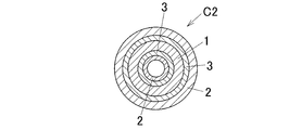
- the aluminum porous body as the anode body 1 constituting the aluminum electrolytic capacitor C1 is formed in a columnar shape, but is not limited thereto, and for example, as shown in FIG. 1B, a cylindrical aluminum porous body You may make it produce the aluminum electrolytic capacitor C2 using the anode material 1 comprised by the mass.
- separators 3 and 3 are attached to the outer peripheral surface and inner peripheral surface of the cylindrical anode material 1, and the inside of the inner peripheral separator 3 and the outer peripheral separator 3 Cathode bodies 2 and 2 are attached to the outside, respectively.
- the porous structure is formed on the inner peripheral surface in addition to the outer peripheral surface of the anode material 1, the surface area can be further increased, and the capacitance can be further improved. Can do.
- an aluminum electrolytic capacitor can be formed by sequentially laminating and placing a semiconductor layer and a conductor layer on the dielectric coating.
- the semiconductor layer can be formed of an inorganic semiconductor such as manganese dioxide or an organic semiconductor such as a conductive polymer, and these can be generally produced by a known method. In the case of forming with a conductive polymer, it can be formed using, for example, a chemical polymerization method and / or an electrolytic polymerization method.
- the solution for forming the semiconductor layer is not particularly limited as long as the solution can form a semiconductor by dipping and / or energization. For example, a solution containing aniline, thiophene, pyrrole and substituted derivatives thereof (for example, 3,4-ethylenedioxythiophene, etc.) can be used. Further, a dopant may be added to this solution.
- arylsulfonic acid or its salt alkylsulfonic acid or its salt, various polymeric sulfonic acid or its salt, etc.
- conductive polymer for example, polyaniline, polythiophene, polypyrrole, polymethylpyrrole, and derivatives thereof
- a semiconductor layer can be formed.
- the conductor layer can be made of, for example, highly conductive carbon or silver, and can be produced by solidifying pasty carbon or silver. These may be laminated.
- Example 1-1 An Al-15 mass% Mg alloy melt was cast and solidified into a cylindrical shape (round bar) having a diameter of 10 mm at a cooling rate of 80 ° C./sec to obtain a cast body.
- the cast body was turned and shaped into a diameter of 5 mm and a length of 20 mm to obtain a round bar-shaped aluminum alloy cast body.
- the cast aluminum alloy was used as a precursor, degreased with ethanol, immersed in a 40% by mass nitric acid aqueous solution at room temperature for 6 hours, washed with water and dried to obtain the porous aluminum body of the present invention.
- FIG. 1C shows an optical micrograph of a cross section of the solidified structure in the precursor of the aluminum porous body.
- an ⁇ -phase 11 of the primary crystal (light gray portion in the figure) is formed in a dendritic crystal, and a second phase 12 (dark in the figure) is formed between the ⁇ -phases 11. (Gray part) is formed continuously.
- the depth (etching depth) of the void formed by elution of the second phase 12 is 0.085 mm from the surface of the porous body, and the width of the void.
- the (pore size) was 2 ⁇ m to 5 ⁇ m.
- the obtained aluminum porous body was immersed in pure water in a boiling state for 5 minutes for chemical conversion pretreatment.
- the aluminum porous body subjected to the chemical conversion pretreatment was immersed in 11 L of pure water to which 1100 g of boric acid and 9.9 g of ammonium pentaborate octahydrate were added, and the initial current value was 500 mA / cm 2 at 90 ° C., constant voltage. Chemical conversion treatment was carried out by holding at 150 V for 10 minutes.
- the aluminum porous body subjected to chemical conversion treatment is immersed in 360 ml of pure water to which 28.8 g of ammonium pentaborate octahydrate is added, and below the surface of the stainless steel container (area: bottom diameter 60 mm ⁇ height 150 mm)
- As a counter electrode 30 ° C., measurement frequency 120 Hz, measurement voltage 0.5 Vr. m. s.
- the capacitance was measured at, it was 8.64 ⁇ F.
- Example 1-2 A molten alloy of Al-9 mass% Mg alloy was cast and solidified into a cylindrical shape (round bar) having a diameter of 10 mm at a cooling rate of 80 ° C./sec to obtain a cast body.
- the cast body was turned and shaped into a diameter of 5 mm and a length of 20 mm to obtain a round bar-shaped aluminum alloy cast body.
- the cast aluminum alloy was used as a precursor, degreased with ethanol, immersed in an 8N aqueous nitric acid solution at 20 ° C. for 6 hours, washed with water and dried to obtain the porous aluminum body of the present invention.
- Example 1-1 After performing chemical conversion pretreatment and chemical conversion treatment in the same manner as in Example 1-1, the capacitance was measured by the same method as in Example 1-1. As a result, it was 4.82 ⁇ F.
- Example 1-3 A molten Al-13 mass% Mg alloy was cast and solidified into a cylindrical shape (round bar) having a diameter of 10 mm at a cooling rate of 30 ° C./sec to obtain a cast body.
- the cast body was turned and shaped into a diameter of 5 mm and a length of 20 mm to obtain a round bar-shaped aluminum alloy cast body.
- the cast aluminum alloy was used as a precursor, degreased with ethanol, immersed in an 8N aqueous nitric acid solution at 20 ° C. for 6 hours, washed with water and dried to obtain the porous aluminum body of the present invention.
- Example 1-1 After performing chemical conversion pretreatment and chemical conversion treatment in the same manner as in Example 1-1, the capacitance was measured by the same method as in Example 1-1, and it was 5.60 ⁇ F.
- Example 1-4 A molten Al-13 mass% Mg alloy was cast and solidified into a cylindrical shape (round bar) having a diameter of 10 mm at a cooling rate of 80 ° C./sec to obtain a cast body.
- the cast body was turned and shaped into a diameter of 5 mm and a length of 20 mm to obtain a round bar-shaped aluminum alloy cast body.
- the cast aluminum alloy was used as a precursor, degreased with ethanol, immersed in a 5N aqueous hydrochloric acid solution at 10 ° C. for 24 hours, washed with water and dried to obtain the porous aluminum body of the present invention.
- Example 1-1 After performing chemical conversion pretreatment and chemical conversion treatment in the same manner as in Example 1-1, the capacitance was measured by the same method as in Example 1-1, and it was 7.00 ⁇ F.
- Example 1-5 A molten Al-13 mass% Mg alloy was cast and solidified into a cylindrical shape (round bar) having a diameter of 10 mm at a cooling rate of 30 ° C./sec to obtain a cast body.
- the cast body was turned and shaped into a diameter of 5 mm and a length of 20 mm to obtain a round bar-shaped aluminum alloy cast body.
- the cast aluminum alloy was used as a precursor, degreased with ethanol, immersed in a 5N aqueous hydrochloric acid solution at 10 ° C. for 24 hours, washed with water and dried to obtain the porous aluminum body of the present invention.
- Example 1-1 After performing chemical conversion pretreatment and chemical conversion treatment in the same manner as in Example 1-1, the capacitance was measured by the same method as in Example 1-1, and it was 5.02 ⁇ F.
- Example 1-6 A molten Al-13 mass% Mg alloy was cast and solidified into a cylindrical shape (round bar) having a diameter of 10 mm at a cooling rate of 80 ° C./sec to obtain a cast body.
- the cast body was turned and shaped into a diameter of 5 mm and a length of 20 mm to obtain a round bar-shaped aluminum alloy cast body.
- the cast aluminum alloy was used as a precursor, degreased with ethanol, immersed in an aqueous solution containing 5N hydrochloric acid and 5N sulfuric acid at 10 ° C. for 24 hours, washed with water and dried to obtain the porous aluminum body of the present invention. Obtained.
- Example 1-1 After performing chemical conversion pretreatment and chemical conversion treatment in the same manner as in Example 1-1, the capacitance was measured by the same method as in Example 1-1, and it was 7.90 ⁇ F.
- the electrode having a high electrostatic capacity can be obtained by elution of the second phase of the coagulated tissue by contacting with an eluent that dissolves the material to form an aluminum porous body having a large number of voids communicating from the surface to the inside. A material can be obtained.
- the reason why the aluminum porous body after the chemical conversion treatment has a high capacitance is that the aluminum porous body has a large surface area.
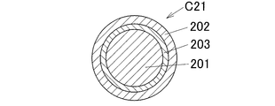
- FIG. 2A is a sectional view schematically showing an aluminum electrolytic capacitor C21 according to the second embodiment of the present invention.
- the capacitor C21 is a cylindrical anode material 201 functioning as an anode, a sheet-like or film-like separator 203 wound around the outer periphery of the anode material 201, and the outer periphery of the separator 203.
- a foil-like cathode material 202 that functions as a cathode.
- the separator 203 and the cathode material 202 are made of a conventionally known material, while the anode material 201 is made of a material specific to this embodiment as will be described later.
- an aluminum electrolytic capacitor is formed by sandwiching a dielectric film made of aluminum oxide formed on an anode body made of aluminum between an anode and a cathode facing the anode.
- porous aluminum body of the present invention As an anode material, a dielectric film is formed on the anode material, and a separator infiltrated with an electrolyte solution serving as a cathode is placed on the dielectric film, whereby an aluminum electrolytic capacitor is obtained. Can be formed.
- separator a known separator such as a porous cellulose membrane can be used.
- the electrolytic solution generally comprises a cation component, an anion component, and a solvent.
- the anion component include weak acids such as boric acid and carboxylic acid
- examples of the cation component include organic bases such as ammonia and amines.
- examples of the solvent include ethylene glycol and ⁇ -butyrolactone.
- the cathode a conventional surface-expanded Al foil or the like can be used.
- the anode material 201 obtained by the present invention is composed of an aluminum porous body (porous material).
- This aluminum porous body has an aluminum alloy cast body formed by casting solidification as a precursor. Then, the precursor is subjected to a predetermined treatment to produce an aluminum intermediate, and a required portion of the aluminum intermediate is eluted (etched) to open a surface, and a large number of continuous voids from the surface to the inside.
- the aluminum porous body of this embodiment having (pores) is obtained.
- An aluminum alloy as a precursor can be expressed as an Al—X alloy in which “X” as an additive component (additive element) is added to Al (aluminum) as a main component (residual component).
- the solidification structure of the precursor has an ⁇ phase composed of primary crystals (that is, an ⁇ -Al phase), and a second phase having a eutectic formed in a continuous manner with the ⁇ phase.
- the primary crystal refers to a crystal that is first formed from a molten metal during casting solidification.
- the second phase has a eutectic of Al and the additive element “X”. The second phase is virtually all connected.
- the isolated second phase may remain as long as the effects of the present invention are not impaired.
- this precursor is immersed in a molten metal bath of “Y” as a bath component (bath metal element) to elute “X”, and a part, preferably all of “X” is expressed as “Y”.
- a molten metal bath of “Y” as a bath component (bath metal element) to elute “X”, and a part, preferably all of “X” is expressed as “Y”.
- Y molten metal bath of “Y”
- Y bath component
- the metal structure of the aluminum intermediate has a residual phase corresponding to the ⁇ phase of the precursor and an elution phase corresponding to the second phase, and the aluminum intermediate is brought into contact with an eluent that dissolves “Y”. And the bath component “Y” elutes preferentially, and the main part of the residual phase corresponding to the ⁇ phase remains, while at least a part, preferably all, of the elution phase corresponding to the second phase elutes. As a result, a large number of continuous voids (pores) are formed in the aluminum intermediate body from the surface to the inside, and the porous aluminum body of this embodiment is obtained.
- additive component “X” examples include elements selected from Ca, Cu, Mg, Zn, Ni, Mn, Bi, In, and Sn. Can be cited as a preferred example.
- the additive component “X” is not limited to one type, and two or more types may be added.
- a part of the additive component “X” to be replaced may be replaced with the bath component “Y”, or all may be replaced with the bath component “Y”.
- the bath component “Y” is a metal element having a melting point lower than that of Al, is less soluble in Al “Y”, and is a different type of element from the additive component “X” to be replaced.
- at least one element selected from Bi and In, that is, Bi and In, and a low-melting-point material in which these are combined can be used.
- Bi can be cited as a preferred example of the bath component “Y”.
- the bath temperature is set lower than the melting point of the Al—X alloy and higher than the melting point of “Y”.
- the bath component “Y” is about 400 to 500 ° C. when Bi is used, and about 200 to 350 ° C. when In is used.
- the precursor component is immersed in the bath component “Y” and the additive component “X” is replaced with the bath component “Y”, it may be performed in an atmospheric atmosphere, but is preferably an oxidation containing a large amount of N 2 , Ar, or the like. This should be done in a controlled atmosphere.
- the Al—X-based alloy constituting the precursor can be regarded as having a hypoeutectic composition with an Al-based addition amount of “X” below the eutectic point.
- the Al-rich alloy phase crystallizes inside the solidification cell structure constituting the ⁇ phase, while the final solidification portion of the solidification cell formed on the outer periphery of the ⁇ phase. Crystallizes an alloy phase (second phase) containing a large amount of additive component “X”.
- the bath component “Y” is placed around the remaining phase of the aluminum intermediate (corresponding to the ⁇ phase).
- the bath component “Y” of the elution phase is preferentially eluted by the eluent, and as a result, the elution phase can be effectively eluted, and a desired void can be reliably formed.
- the ⁇ phase may also be eluted slightly, but this is not a problem as long as a continuous void is formed and the shape of the porous body is maintained.
- the precursor has a hypereutectic composition in which the addition amount of “X” exceeds the eutectic point
- a crystallized product whose primary crystal is composed of the additive component “X” or an alloy containing a large amount of the additive component “X” Become a phase.
- many parts of the primary crystals are eluted by the eluent.
- the voids are too large, and the surface area cannot be sufficiently expanded, or the porosity cannot be maintained, which is not preferable.
- an element other than “X” (third component) is added within the range of the eutectic composition to the Al—X alloy as the precursor as necessary or unavoidable. You can also.
- the general addition amount of “X” in the precursor is not more than the eutectic composition and is 1% by mass or more, desirably 5% by mass or more, and more desirably 10% by mass or more. That is, when “X” is added in this amount, as described above, in the aluminum intermediate in which the additive component “X” is replaced with the bath component “Y”, the bath component “Y” is added to the remaining phase ( ⁇ phase). And the bath component “Y” is preferentially eluted by the eluate, and the desired porous structure (void) can be formed when the elution phase is eluted.
- the eutectic composition in the present invention is, for example, 35% by mass with the smallest amount of Mg in the phase diagram in the case of an Al—Mg alloy, and 15% by mass in the case of an Al—In alloy. In the case of an Al—Zn alloy, the content is 36% by mass.
- the smaller the solidification cell as the ⁇ phase during casting solidification the more porous aluminum is obtained.
- the surface area of the material can be increased. Therefore, it is preferable to reduce the solidification cell during casting solidification.
- the cooling rate in the vicinity of the freezing point may be adjusted to 1 ° C./sec or higher, preferably 5 ° C./sec or higher, more preferably 10 ° C./sec or higher.
- dendrites in at least a part of the ⁇ -phase solidification cell in the precursor, that is, the remaining phase cells in the aluminum intermediate, and more preferably all of them are formed in dendrites.
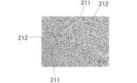
- the precursor of the aluminum porous body related to the present invention has an ⁇ phase 211 formed by dendrites as shown in the light gray portion of the figure.
- the second phase 212 (the dark gray portion in the figure) is continuously formed between the dendrites.
- the precursor may be subjected to a drawing process or a rolling process for shaping the outer shape.
- the precursor is processed with a high deformation rate, the solidified structure collapses, the crystallized product as the second phase is fragmented, and the eluted phase of the aluminum intermediate (corresponding to the second phase) is eluted.
- a desired void may not be obtained.
- the surface of the precursor may be left as it is, but the cast solidified surface is cut (deleted) so that the additive component “X” can be replaced with the bath component “Y” quickly and uniformly. Is good.
- an acid aqueous solution can be exemplified.
- the acid contained in the acid aqueous solution it is preferable to use nitric acid or sulfuric acid in which Al does not easily elute, and hydrochloric acid or the like can also be used.
- An aluminum porous body obtained by treating the above aluminum intermediate with an eluate can be used as a capacitor electrode material.
- a dielectric coating is formed on the anode body.
- the method for forming the dielectric film is not particularly limited, but it is preferable to apply a chemical conversion treatment by anodic oxidation.
- Hydration treatment is generally performed in pure water as pre-chemical treatment.
- Other pretreatment methods include immersion in hydrogen peroxide, cleaning with an acid or alkaline treatment solution, vacuum or atmospheric heat treatment, dechlorination treatment, hydration treatment in an aqueous solution to which an amine is added, thermal oxide film It can be applied alone or in combination from known pretreatment methods including treatment with an acid or alkali solution after formation, and hydration treatment performed after electrolytic etching is applied to the aluminum foil.
- the chemical conversion treatment solution known ones can be used, and examples include an aqueous solution in which one or more of boric acid, ammonium borate, adipic acid, ammonium adipate, phosphoric acid and its salt, citric acid and its salt, etc. are mixed. it can.
- the EIAJ method can be exemplified, but is not limited thereto.
- the chemical conversion treatment may be performed a plurality of times, the chemical conversion liquid may be changed for each chemical conversion treatment according to a known method, and heat treatment or washing may be performed between the chemical conversion treatment and the chemical conversion treatment.
- the conversion voltage may be set to different values in a plurality of conversion processes.
- the precursor and the aluminum intermediate are formed in a columnar shape, but are not limited thereto.
- the precursor and the aluminum intermediate are cylindrical, elliptical cylinder, elliptical cylinder, prismatic, rectangular cylinder, plate It may be formed in any shape such as a flat shape.
- a flat shape For example, in order to effectively utilize the surface of the precursor and enlarge the surface area, it is advantageous to form the surface in an elliptical shape or a flat shape.
- the precursor and the aluminum intermediate body are hollow like a cylinder or the like, it can be preferentially eluted from the inner peripheral surface, so that a higher surface area can be obtained.
- an aluminum alloy cast body as a precursor for example, a method in which a molten aluminum alloy having a predetermined alloy composition is cast into a mold close to the final shape and solidified, and then the shape is adjusted by slightly shaving the surface, etc. Can be used.
- a method of producing a precursor having an elliptical cross section by compressing a round bar-shaped aluminum alloy cast from above and below to such an extent that a solidified structure remains can be employed.
- the aluminum porous body as the anode material 201 constituting the aluminum electrolytic capacitor C21 is formed in a columnar shape, but is not limited thereto, and for example, as shown in FIG. 2B, a cylindrical aluminum porous body You may make it produce the aluminum electrolytic capacitor C22 using the anode material 201 comprised by the mass.
- the capacitor C22 of this modification has separators 203, 203 attached to the outer peripheral surface and the inner peripheral surface of a cylindrical anode material 201, and the inside of the inner peripheral separator 203 and the outer peripheral separator 203.
- Cathode materials 202 and 202 are respectively attached to the outside.
- the porous structure is formed on the inner peripheral surface in addition to the outer peripheral surface of the anode material 201, the surface area can be further increased, and the capacitance can be further improved. Can do.
- an aluminum electrolytic capacitor can be formed by sequentially laminating and placing a semiconductor layer and a conductor layer on the dielectric coating.
- the semiconductor layer can be formed of an inorganic semiconductor such as manganese dioxide or an organic semiconductor such as a conductive polymer, and these can be generally produced by a known method. In the case of forming with a conductive polymer, it can be formed using, for example, a chemical polymerization method and / or an electrolytic polymerization method.
- the solution for forming the semiconductor layer is not particularly limited as long as the solution can form a semiconductor by dipping and / or energization. For example, a solution containing aniline, thiophene, pyrrole and substituted derivatives thereof (for example, 3,4-ethylenedioxythiophene, etc.) can be used. Further, a dopant may be added to this solution.
- arylsulfonic acid or its salt alkylsulfonic acid or its salt, various polymeric sulfonic acid or its salt, etc.
- conductive polymer for example, polyaniline, polythiophene, polypyrrole, polymethylpyrrole, and derivatives thereof
- a semiconductor layer can be formed.
- the conductor layer can be made of, for example, highly conductive carbon or silver, and can be produced by solidifying pasty carbon or silver. These may be laminated.
- Example 2-1 An Al-15 mass% Mg alloy melt was cast and solidified into a cylindrical shape (round bar) having a diameter of 10 mm at a cooling rate of 80 ° C./sec to obtain a cast body. The cast body was turned and shaped into a diameter of 5 mm and a length of 20 mm to obtain a round bar-shaped aluminum alloy cast body. Then, the aluminum alloy casting was used as a precursor, and immersed in a molten metal bath (500 ° C.) of Bi as a bath component in the atmosphere for 1 minute to obtain an aluminum intermediate. Subsequently, the aluminum intermediate was immersed in nitric acid having a concentration of 40% by mass at room temperature for 6 hours, washed with water and dried to obtain an aluminum porous body of Example 2-1 related to the present invention.
- a molten metal bath 500 ° C.
- Bi molten metal bath
- FIG. 2C shows an optical micrograph of a cross section of the solidified structure in the precursor of the aluminum porous body.
- the ⁇ phase 211 (light gray part in the figure) is formed in a dendritic crystal
- the second phase 212 (dark gray part in the figure) is interposed between the ⁇ phases 211. ) Are formed continuously.
- the depth of the void formed by the elution of the elution phase was 0.2 mm to 0.3 mm from the surface of the porous body.
- the void width was 2 ⁇ m to 5 ⁇ m.
- the obtained aluminum porous body was immersed in boiling pure water for 5 minutes for chemical conversion pretreatment.
- the aluminum porous body subjected to the chemical conversion pretreatment was immersed in 11 L of pure water to which 1100 g of boric acid and 9.9 g of ammonium pentaborate octahydrate were added, and the initial current value was 500 mA / cm 2 at 90 ° C., constant voltage.
- Chemical conversion treatment was carried out by holding at 150 V for 10 minutes.
- the aluminum porous body subjected to the chemical conversion treatment is immersed in 360 ml of pure water to which 28.8 g of ammonium pentaborate octahydrate is added, and below the surface of the stainless steel container (area: diameter 60 mm ⁇ height 150 mm)
- As a counter electrode 30 ° C., measurement frequency 120 Hz, measurement voltage 0.5 Vr. m. s.
- the capacitance was measured, it was 12.94 ⁇ F.
- Example 2 was carried out in the same manner as in Example 2-1 except that the cooling rate during casting was set to 50 ° C./sec, and the immersion time of Bi in the molten metal bath in the aluminum intermediate was set to 5 minutes. 2 porous aluminum was obtained.
- FIG. 2D shows an SEM photograph of the cross section of the metal structure in the replica of the porous aluminum body of Example 2-2.
- the replica is obtained by dissolving and removing the Al base material after forming an oxide film on the pore inner surface of the aluminum porous body.
- voids (corresponding to the residual phase) 213 after removal of the residual phase are formed, and are formed on the inner surfaces of the pores (voids) between the voids 213 after removal of the residual phase.
- An oxide film 214 (the dark gray portion in the figure) is continuously formed.
- Example 2-2 the aluminum porous body of Example 2-2 was analyzed, and as a result, the depth of the void (etching depth) after removal of the eluted phase was 0.35 mm to 0.5 mm from the surface of the porous body.
- the width (pore average diameter) was 10 ⁇ m.
- Example 2-2 the aluminum porous body was subjected to chemical conversion pretreatment and chemical conversion treatment in the same manner as in Example 2-1, and the capacitance was measured. As a result, it was 6.12 ⁇ F.
- Example 2-3 A molten Al-13 mass% Mg alloy was cast and solidified into a cylindrical shape (round bar) having a diameter of 10 mm at a cooling rate of 30 ° C./sec to obtain a cast body. The cast body was turned and shaped into a diameter of 5 mm and a length of 20 mm to obtain a round bar-shaped aluminum alloy cast body. Then, the aluminum alloy casting was used as a precursor, and immersed in a molten metal bath (500 ° C.) of Bi as a bath component in the atmosphere for 1 minute to obtain an aluminum intermediate. Subsequently, the aluminum intermediate was immersed in an 8N aqueous nitric acid solution at 20 ° C. for 6 hours, washed with water and dried to obtain an aluminum porous body of Example 2-3 related to the present invention.
- a molten metal bath 500 ° C.
- Example 2-3 the aluminum porous body was subjected to pre-chemical conversion treatment and chemical conversion treatment in the same manner as in Example 2-1, and the capacitance was measured. As a result, it was 8.70 ⁇ F.
- Example 2-4 An aluminum porous body of Example 2-4 related to the present invention was obtained in the same manner as Example 2-3 except that the immersion time of Bi in a molten metal bath (500 ° C.) was 5 minutes.
- Example 2-4 the aluminum porous body was subjected to chemical conversion pretreatment and chemical conversion treatment in the same manner as in Example 2-1, and the capacitance was measured. As a result, it was 9.10 ⁇ F.
- an aluminum alloy cast body having a solidified structure having an ⁇ -Al phase and a second phase formed in a continuous manner with the ⁇ -Al phase by casting solidification of an aluminum alloy is referred to as “Al”.
- the precursor is immersed in a molten metal bath having a lower melting point than the bath component “Y”, and the element “X” is eluted and replaced with “Y”, and the remaining phase corresponding to the ⁇ phase,
- An aluminum porous body having a large number of voids communicating from the surface to the inside is prepared by preparing an aluminum intermediate having a metallographic structure having an elution phase corresponding to a phase and contacting with an eluent that dissolves “Y” of the intermediate
- An electrode material having a high capacitance can be obtained.
- the reason why the aluminum porous body after the chemical conversion treatment has a high capacitance is that the aluminum porous body has a large surface area.
- the method for producing an aluminum porous body of the present invention can be suitably used when producing an anode material for an aluminum electrolytic capacitor or an aluminum solid electrolytic capacitor.
Landscapes
- Engineering & Computer Science (AREA)
- Chemical & Material Sciences (AREA)
- Power Engineering (AREA)
- Materials Engineering (AREA)
- Mechanical Engineering (AREA)
- Metallurgy (AREA)
- Organic Chemistry (AREA)
- Microelectronics & Electronic Packaging (AREA)
- ing And Chemical Polishing (AREA)
Abstract
広い表面積を備えたアルミニウム多孔質体の製造方法を提供する。 本発明のアルミニウム多孔質体の製造方法は、アルミニウム合金の鋳造凝固によって、α-Al相11と、α-Al相と互いに入り組んでかつ連続して形成された第2相12とを有する凝固組織のアルミニウム合金鋳造体を作製する工程と、前記アルミニウム合金鋳造体を前駆体として第2相を溶解する溶出液と接触させることにより、前記前駆体における凝固組織の第2相12を溶出して、表面から内部に連通する多数の空隙を有するアルミニウム多孔質体を製造する工程とを備える。
Description
この発明は、例えばアルミニウム電解コンデンサやアルミニウム固体電解コンデンサ等における電極材の材料として好適に用いられるアルミニウム多孔質体の製造方法およびその関連技術に関する。
アルミニウム電解コンデンサおよびアルミニウム固体電解コンデンサは比較的安価で高容量が得られるため、パーソナルコンピュータやテレビ等の家電製品や車載の電気製品用に広く使用されている。アルミニウム電解コンデンサは、一般的に陽極箔と陰極箔とをセパレータを介在させて卷回してコンデンサ素子とし、このコンデンサ素子に電解液を含浸してケース等に収納し、封孔することによって製造されている。例えば陽極箔には、アルミニウム等の弁作用金属の箔に化学的あるいは電気化学的にエッチングにより拡面処理が行われ、この拡面処理した箔の表面に化成処理をすることにより酸化被膜層が形成されている。
コンデンサにおいてはその最も重要な性能の一つである静電容量の向上を目的として、従来より、多数の技術が提案されている。例えば特許文献1、2に示すようにアルミニウム箔材料の開発に関する技術や、特許文献3に示すようにエッチング処理技術の開発に関する技術を基に、種々の拡面処理にアプローチして高容量化が進められてきた。
しかしながら、上記特許文献1~3の技術によるアルミニウム電解コンデンサの高容量化の延びは、近年鈍化しており、従来技術の延長では静電容量を大幅に向上させることは困難になってきている。
一方で、アルミニウム電解コンデンサにおいて大幅な高容量化を目的として、特許文献4に示すように陽極箔に弁作用金属の粉末を噴射する技術、エッチング位置を規則正しく配列させるために、特許文献5に示す印刷法を用いる技術や、特許文献6に示すようにリソグラフィーを用いる技術が提案されているが、特許文献4~6のいずれの技術もコストが高い等の課題を抱えており、実用化には至っていない。
本発明の好ましい実施形態は、関連技術における上述した及び/又は他の問題点に鑑みてなされたものである。本発明の好ましい実施形態は、既存の方法及び/又は装置を著しく向上させることができるものである。
本発明は、上記の課題に鑑みてなされたものであり、複雑な工程を必要とせずに低コストで製造でき、製造されたアルミニウム多孔質体は十分に広い表面積を備えることにより、例えばアルミニウム電解コンデンサの陽極体として用いた場合に、静電容量を大幅に向上させることができるアルミニウム多孔質体の製造方法およびその関連技術を提供することを目的とする。
本発明のその他の目的及び利点は、以下の好ましい実施形態から明らかであろう。
上記目的を達成するため、本発明は以下の構成を要旨とするものである。
[1]アルミニウム合金の鋳造凝固によって、α-Al相と、α-Al相と互いに入り組んでかつ連続して形成された第2相とを有する凝固組織のアルミニウム合金鋳造体を作製する工程と、
前記アルミニウム合金鋳造体を前駆体として第2相を溶解する溶出液と接触させることにより、前記前駆体における凝固組織の第2相を溶出して、表面から内部に連通する多数の空隙を有するアルミニウム多孔質体を製造する工程とを備えることを特徴とするアルミニウム多孔質体の製造方法。
前記アルミニウム合金鋳造体を前駆体として第2相を溶解する溶出液と接触させることにより、前記前駆体における凝固組織の第2相を溶出して、表面から内部に連通する多数の空隙を有するアルミニウム多孔質体を製造する工程とを備えることを特徴とするアルミニウム多孔質体の製造方法。
[2]α-Al相には、樹枝状晶が含まれている前項1に記載のアルミニウム多孔質体の製造方法。
[3]前駆体としてのアルミニウム合金は、主体成分としての「Al」に添加成分としての「X」が添加されたAl-X系合金によって構成され、
「X」は「Al」に対して共晶反応を呈する元素であり、
前駆体としてのAl-X系合金は、Alベースで「X」の添加量が共晶点以下の亜共晶組成である前項1または2に記載のアルミニウム多孔質体の製造方法。
「X」は「Al」に対して共晶反応を呈する元素であり、
前駆体としてのAl-X系合金は、Alベースで「X」の添加量が共晶点以下の亜共晶組成である前項1または2に記載のアルミニウム多孔質体の製造方法。
[4]「X」は「Al」に対し卑な金属である前項3に記載のアルミニウム多孔質体の製造方法。
[5]「X」はMgである前項4に記載のアルミニウム多孔質体の製造方法。
[6]溶出液が酸性水溶液である前項1~5のいずれか1項に記載のアルミニウム多孔質体の製造方法。
[7]溶出液が硝酸、硫酸、塩酸の少なくとも1種を含有する酸性水溶液である前項6に記載のアルミニウム多孔質体の製造方法。
[8]アルミニウム合金の鋳造凝固によって、α-Al相と、α-Al相と互いに入り組んでかつ連続して形成された第2相とを有する凝固組織のアルミニウム合金鋳造体を作製する工程と、
前記アルミニウム合金鋳造体を前駆体として第2相を溶解する溶出液と接触させることにより、前記前駆体における凝固組織の第2相を溶出して、表面から内部に連通する多数の空隙を有するアルミニウム多孔質体を製造する工程とを備えることを特徴とするコンデンサ用電極材の製造方法。
前記アルミニウム合金鋳造体を前駆体として第2相を溶解する溶出液と接触させることにより、前記前駆体における凝固組織の第2相を溶出して、表面から内部に連通する多数の空隙を有するアルミニウム多孔質体を製造する工程とを備えることを特徴とするコンデンサ用電極材の製造方法。
[9]α-Al相には、樹枝状晶が含まれている前項8に記載のコンデンサ用電極材の製造方法。
[10]前駆体としてのアルミニウム合金は、主体成分としての「Al」に添加成分としての「X」が添加されたAl-X系合金によって構成され、
「X」は「Al」に対して共晶反応を呈する元素であり、
前駆体としてのAl-X系合金は、Alベースで「X」の添加量が共晶点以下の亜共晶組成である前項8または9に記載のコンデンサ用電極材の製造方法。
「X」は「Al」に対して共晶反応を呈する元素であり、
前駆体としてのAl-X系合金は、Alベースで「X」の添加量が共晶点以下の亜共晶組成である前項8または9に記載のコンデンサ用電極材の製造方法。
[11]「X」は「Al」に対し卑な金属である前項10に記載のコンデンサ用電極材の製造方法。
[12]「X」はMgである前項11に記載のコンデンサ用電極材の製造方法。
[13]溶出液が酸性水溶液である前項8~12のいずれか1項に記載のコンデンサ用電極材の製造方法。
[14]溶出液が硝酸、硫酸、塩酸の少なくとも1種を含有する酸性水溶液である前項13に記載のコンデンサ用電極材の製造方法。
[15]前項1~7のいずれか1項に記載の製造方法により得られたアルミニウム多孔質体に化成処理を施してコンデンサ用電極材を製造するようにしたことを特徴とするコンデンサ用電極材の製造方法。
[16]前項8~15のいずれか1項に記載の製造方法により得られたコンデンサ用電極材を用いてコンデンサを製造するようにしたことを特徴とするコンデンサの製造方法。
[17]前項15に記載の製造方法により得られたコンデンサ用電極材を陽極材とするコンデンサを製造するようにしたことを特徴とするコンデンサの製造方法。
[18]前項1~7のいずれか1項に記載の製造方法によって得られたことを特徴とするアルミニウム多孔質体。
[19]前項8~15のいずれか1項に記載の製造方法によって得られたことを特徴とするコンデンサ用電極材。
[20]前項16または17に記載の製造方法によって得られたことを特徴とするコンデンサ。
[21]表面から内部に連通した多数の空隙を有するアルミニウム多孔質体の製造方法であって、
「Al」に添加成分としての「X」が添加されたAl-X系合金の鋳造体によって構成され、α-Al相と、α-Al相と互いに入り組んで形成される第2相とを有する凝固組織の前駆体を作製する工程と、
「Al-X系合金」よりも低融点である浴成分「Y」の溶融金属浴に前記前駆体を浸漬して、「X」を溶出させるとともに「Y]と置換して、α-Al相に相当する残存相と、第2相中の「X」が「Y」に置換された溶出相とを有する金属組織のアルミニウム中間体を作製する工程と、
「Y」を溶解する溶出液によって、前記アルミニウム中間体における前記溶出相を溶出する工程とを備えることを特徴とするアルミニウム多孔質体の製造方法。
「Al」に添加成分としての「X」が添加されたAl-X系合金の鋳造体によって構成され、α-Al相と、α-Al相と互いに入り組んで形成される第2相とを有する凝固組織の前駆体を作製する工程と、
「Al-X系合金」よりも低融点である浴成分「Y」の溶融金属浴に前記前駆体を浸漬して、「X」を溶出させるとともに「Y]と置換して、α-Al相に相当する残存相と、第2相中の「X」が「Y」に置換された溶出相とを有する金属組織のアルミニウム中間体を作製する工程と、
「Y」を溶解する溶出液によって、前記アルミニウム中間体における前記溶出相を溶出する工程とを備えることを特徴とするアルミニウム多孔質体の製造方法。
[22]α-Al相が樹枝状晶を含む前項21に記載のアルミニウム多孔質体の製造方法。
[23]「X」は「Al」に対して共晶反応を呈する元素であり、前駆体としてのAl-X系合金は、Alベースで元素「X」の添加量が共晶点以下の範囲である亜共晶組成である前項21または22に記載のアルミニウム多孔質体の製造方法。
[24]「X」がMgである前項23に記載のアルミニウム多孔質体の製造方法。
[25]浴成分「Y」は、「X」とは異なる種類の元素であり、かつBi、Inの中から選択される少なくとも1種以上の元素である前項21~24のいずれか1項に記載のアルミニウム多孔質体の製造方法。
[26]溶出液が酸性水溶液である前項21~25のいずれか1項に記載のアルミニウム多孔質体の製造方法。
[27]溶出液が硝酸を含む水溶液である前項26に記載のアルミニウム多孔質体の製造方法。
[28]表面から内部に連通した多数の空隙を有するコンデンサ用電極材の製造方法であって、
「Al」に添加成分としての「X」が添加されたAl-X系合金の鋳造体によって構成され、α-Al相と、α-Al相と互いに入り組んで形成される第2相とを有する凝固組織の前駆体を作製する工程と、
「Al-X系合金」よりも低融点である浴成分「Y」の溶融金属浴に前記前駆体を浸漬して、「X」を溶出させるとともに「Y]と置換して、α-Al相に相当する残存相と、第2相中の「X」が「Y」に置換された溶出相とを有する金属組織のアルミニウム中間体を作製する工程と、
「Y」を溶解する溶出液によって、前記アルミニウム中間体における前記溶出相を溶出する工程とを備えることを特徴とするコンデンサ用電極材の製造方法。
「Al」に添加成分としての「X」が添加されたAl-X系合金の鋳造体によって構成され、α-Al相と、α-Al相と互いに入り組んで形成される第2相とを有する凝固組織の前駆体を作製する工程と、
「Al-X系合金」よりも低融点である浴成分「Y」の溶融金属浴に前記前駆体を浸漬して、「X」を溶出させるとともに「Y]と置換して、α-Al相に相当する残存相と、第2相中の「X」が「Y」に置換された溶出相とを有する金属組織のアルミニウム中間体を作製する工程と、
「Y」を溶解する溶出液によって、前記アルミニウム中間体における前記溶出相を溶出する工程とを備えることを特徴とするコンデンサ用電極材の製造方法。
[29]α-Al相が樹枝状晶を含む前項28に記載のコンデンサ用電極材の製造方法。
[30]「X」は「Al」に対して共晶反応を呈する元素であり、前駆体としてのAl-X系合金は、Alベースで元素「X」の添加量が共晶点以下の範囲である亜共晶組成である前項28または29に記載のコンデンサ用電極材の製造方法。
[31]「X」がMgである前項30に記載のコンデンサ用電極材の製造方法。
[32]浴成分「Y」は、「X」とは異なる種類の元素であり、かつBi、Inの中から選択される少なくとも1種以上の元素である前項28~31のいずれか1項に記載のコンデンサ用電極材の製造方法。
[33]溶出液が酸性水溶液である前項28~32のいずれか1項に記載のコンデンサ用電極材の製造方法。
[34]溶出液が硝酸を含む水溶液である前項33に記載のコンデンサ用電極材の製造方法。
[35]前項21~27のいずれか1項に記載の製造方法により得られたアルミニウム多孔質体に化成処理を施してコンデンサ用電極材を製造するようにしたことを特徴とするコンデンサ用電極材の製造方法。
[36]前項28~35のいずれか1項に記載の製造方法により得られたコンデンサ用電極材を用いてコンデンサを製造するようにしたことを特徴とすることを特徴とするコンデンサの製造方法。
[37]前項35に記載の製造方法により得られたコンデンサ用電極材を陽極材とするコンデンサを製造するようにしたことを特徴とするコンデンサの製造方法。
[38]前項21~27のいずれか1項に記載の製造方法によって得られたことを特徴とするアルミニウム多孔質体。
[39]前項28~35のいずれか1項に記載の製造方法によって得られたことを特徴とするコンデンサ用電極材。
[40]前項36または37に記載の製造方法によって得られたことを特徴とするコンデンサ。
本発明の製造方法によれば、簡単かつ低コストで、十分な表面積を有するアルミニウム多孔質体を得ることができる。こうして得られた多孔質体をアルミニウムコンデンサの陽極体として用いた場合、静電容量を大幅に向上させることができる。
<第1実施形態>
図1Aはこの発明により得られるアルミニウム電解コンデンサC1を模式化して示す断面図である。同図に示すようにこのコンデンサC1は、陽極として機能する円柱状の陽極材1と、陽極材1の外周に巻き付けられたシート状ないしフィルム状のセパレータ3と、そのセパレータ3の外周に巻き付けられ、かつ陰極として機能する箔状の陰極体2とを備えている。なお、セパレータはコンデンサの構造により用いない場合もある。
図1Aはこの発明により得られるアルミニウム電解コンデンサC1を模式化して示す断面図である。同図に示すようにこのコンデンサC1は、陽極として機能する円柱状の陽極材1と、陽極材1の外周に巻き付けられたシート状ないしフィルム状のセパレータ3と、そのセパレータ3の外周に巻き付けられ、かつ陰極として機能する箔状の陰極体2とを備えている。なお、セパレータはコンデンサの構造により用いない場合もある。
セパレータ3および陰極材2は、従来より周知の材料が用いられる一方、陽極材1は、後に説明するように本実施形態特有の材料が用いられている。
一般にアルミニウム電解コンデンサは、アルミニウムからなる陽極材上に形成された酸化アルミニウムからなる誘電体被膜を、陽極と、陽極と対向する陰極とで挟み込んで形成される。
本発明のアルミニウム多孔質体を陽極材として、陽極材上に誘電体被膜を形成し、陰極となる電解液の浸み込んだセパレータを誘電体被膜上に載置することにより、アルミニウム電解コンデンサを形成することができる。
セパレータは、セルロース多孔質膜をはじめとする公知のものを用いることができる。
電解液は公知のものを用いることができる。電解液は、一般にカチオン成分と、アニオン成分と、溶媒とからなる。アニオン成分としては、例えばホウ酸やカルボン酸などの弱酸が挙げられ、カチオン成分としては、例えばアンモニアやアミンなどの有機塩基が挙げられる。溶媒としては、例えばエチレングリコールやγ-ブチロラクトンなどが挙げられる。陰極としては、従来の拡面処理されたAl箔等を用いることができる。
この発明により得られる陽極材1は、アルミニウム多孔質体(ポーラス材料)によって構成されている。このアルミニウム多孔質体は、鋳造凝固によって成形されたアルミニウム合金鋳造体を前駆体としている。そしてその前駆体の所要部を溶出(エッチング)することによって、表面に開口し、かつ表面から内部にかけて連通する多数の空隙(気孔)を有するアルミニウム多孔質体を得るようにしている。
前駆体としてのアルミニウム合金は、後述するように主体成分(主体元素)としてのAl(アルミニウム)に、添加成分(添加元素)としての「X」が添加されたAl-X系合金として表すことができる。
前駆体の凝固組織は、初晶からなるα相(すなわちα-Al相)と、α相と互いに入り組んで連続して形成される共晶を有する第2相とを有している。初晶とは、鋳造凝固において溶湯から最初に生成する結晶をいう。第2相は、Alと添加元素「X」との共晶を有する。第2相は実質的に全てが繋がっている。ただし、孤立した第2相が、本発明の効果を損なわない範囲で残っていても構わない。
第2相における添加成分「X」の含有率(質量%)は、α相における含有率に比べて多く、さらに、添加成分「X」はAlに対して卑な金属、即ちAlよりも水溶液中の標準電極電位が低い金属を用いることができる。
前駆体を添加成分「X」を溶解する液に接触させると、添加成分「X」が優先的に溶出し、その結果α相が残存しつつ、第2相の少なくとも一部、好ましくは全部が溶出することによって、前駆体に、表面から内部に連通し、かつ連続する多数の空隙(気孔)が形成されて、本実施形態のアルミニウム多孔質体が得られる。
添加成分「X」としては、Alと融点が近く扱いやすいことからMgを好適に用いることができる。なお添加成分「X」は、1種類に限られず、2種類以上添加されていても良い。
前駆体を構成するAl-X系合金は、Alベースで「X」の添加量が共晶点以下の亜共晶組成であるとみることもできる。このように亜共晶組成の場合には、α相を構成する凝固セル内部にAlリッチの合金相が晶出する一方で、α相の外周に形成される凝固セルの最終凝固部には添加成分「X」を多く含む合金相(第2相)が晶出するため、第2相が溶出液によって優先溶出する。従って所望の空隙を確実に形成することができる。
α相もわずかに溶出することもあるが、連通した空隙が形成されるとともに多孔質体の形状が維持される範囲において問題とはならない。
なお前駆体が、「X」の添加量が共晶点を超える過共晶組成の場合には、初晶が添加成分「X」からなる晶出物、または添加成分「X」を多く含む合金相の晶出物となるので、その初晶の多くの部分が溶出液によって溶出されてしまう。そうすると空隙が大きすぎて表面積を十分に拡大することができなかったり、多孔質を維持できない場合があり、好ましくない。
また、前駆体としてのAl-X系合金には、必要に応じてまたは不可避的に、「X」以外の元素(第3の成分)が共晶組成の範囲内で添加されていてもよい。
前駆体中の「X」の一般的な添加量は、共晶組成以下であって1質量%以上、望ましくは5質量%以上、さらに望ましくは10質量%以上である。すなわちこの量で「X」を添加した場合には、既述した通り、添加成分「X」を多く含む合金相がα相の外周に多く晶出するため、溶出液によって添加成分「X」が優先溶出し、第2相を溶出した際に、所望の多孔質構造(空隙)を形成することができる。本発明における共晶組成とは、Al-Mg合金の場合には、状態図の中の最もMg量の少ない35質量%であり、Al-In合金の場合には、15質量%であり、Al-Zn合金の場合には、36質量%である。
また、第2相を優先溶出させるため、鋳造時のα相からなる凝固セルが小さいほど、表面積を大きくすることができる。従って鋳造凝固時の凝固セルを小さくするのが良い。一般に添加成分「X」の添加量が多いほど、また凝固点近傍の温度での冷却速度が速いほど、凝固セルが小さくなるとともに、凝固セルが粒状(円形状や楕円形状)の晶出物から樹枝状晶へと複雑形状に変化するため、表面積を拡大させることができる。例えば凝固点近傍での冷却速度が1℃/sec以上、望ましくは5℃/sec以上、さらに望ましくは10℃/sec以上となるように調整するのが良い。
α相の凝固セルの少なくとも一部に樹枝状晶を形成するのが良く、より好ましくは全てを樹枝状晶に形成するのが良い。
例えば後の実施例で詳述するが、図1Cに示すように本発明に関連したアルミニウム多孔質体は、初晶α相11(同図の薄いグレーの部分)が樹枝状晶によって構成されており、そのα相11間には、第2相が溶出して形成された空隙12(同図の濃いグレーの部分)が連続して形成されている。
前駆体としてのアルミニウム合金鋳造体に対し、鋳造凝固時の凝固組織が残存するのであれば、変形率の小さい軽度の加工を行っても良い。例えば前駆体に対し、外形を整形するための引抜加工や圧延加工等の加工を行うようにしても良い。
ただし前駆体に変形率の大きい加工を行うと、凝固組織が崩壊し、第2相としての晶出物が分断されてしまい、その晶出物を溶出した際に、所望の空隙(多孔質構造)を得ることができないおそれがある。
前駆体の表面(鋳造凝固表面)は、そのままでも良いが、第2相のエッチング(溶出)を速く均一に行えるように、鋳造凝固表面を切削(削除)しておくのが良い。
本実施形態において、前駆体の添加成分「X」を溶解するための溶出液としては、酸水溶液を例示できる。酸水溶液中に含まれる酸は、Alが溶出し難い硝酸または硫酸を用いるのが好ましく、塩酸等を用いることもできる。
上記前駆体を溶出液で処理して得られたアルミニウム多孔質体をコンデンサ用電極材として用いることができる。アルミニウム多孔質体をコンデンサ用陽極材として用いる場合には、陽極体上に誘電体被膜を形成する。誘電体被膜を形成する方法は特に限定されないが、陽極酸化による化成処理を適用することが好ましい。
化成前処理として一般的には純水中で水和処理を行う。その他、化成前処理の方法としては、過酸化水素水への浸漬、酸またはアルカリ性処理液による洗浄、真空もしくは雰囲気熱処理、脱塩素処理、アミンを添加した水溶液中での水和処理、熱酸化被膜形成後の酸またはアルカリ溶液での処理、アルミニウム箔に電解エッチングを施した後に行う水和処理も含めた公知の前処理方法の中から単独もしくは組み合わせて適用することができる。
化成処理液は公知のものを使用でき、ホウ酸、ホウ酸アンモニウム、アジピン酸、アジピン酸アンモニウム、リン酸およびその塩、クエン酸およびその塩等の中から1種もしくは複数種混合した水溶液を例示できる。
化成方法としては、EIAJ法を例示できるが、これに限定されるものではない。化成処理は複数回実施してもよく、公知の方法に従い、化成処理ごとに化成液を変えてもよく、化成処理と化成処理の間に熱処理若しくは洗浄を実施しても良い。また、複数回の化成処理においては化成電圧を異なる値としても良い。
本実施形態において前駆体は、円柱状に形成されているが、それだけに限られず、本発明において前駆体は、円筒状、楕円柱状、楕円筒状、角柱状、角筒状、板状等の扁平状等、どのような形状に形成しても良い。例えば前駆体の表面を有効に活用して、表面積を拡大するためには、楕円状や扁平状に形成するのが有利である。また、前駆体が筒状等のように内部が空洞となっている場合には、内周面からも優先溶出させることができるため、より高い表面積を得ることができる。
前駆体としてのアルミニウム合金鋳造体を製造する方法は、例えば最終形状に近い鋳型に所定の合金成分のアルミニウム合金溶湯を鋳込んで凝固させた後、表面を若干削って形状を整える方法等を好適に用いることができる。
さらに本実施形態においては、丸棒状のアルミニウム合金鋳造体を凝固組織が残存する程度に上下から圧縮して断面が楕円状の前駆体を製造する方法等も採用することができる。
なお上記実施形態においては、アルミニウム電解コンデンサC1を構成する陽極体1としてのアルミニウム多孔質体が円柱状に形成されているが、それだけに限られず、例えば図1Bに示すように、円筒状のアルミニウム多孔質体によって構成された陽極材1を用いて、アルミニウム電解コンデンサC2を作製するようにしても良い。
同図に示すようにこの変形例のコンデンサC2は、円筒状の陽極材1の外周面および内周面にセパレータ3,3が取り付けられるとともに、内周のセパレータ3の内部および外周のセパレータ3の外部に陰極体2,2がそれぞれ取り付けられている。
この変形例のコンデンサC2においては、陽極材1の外周面に加えて内周面にも多孔質構造が形成されるため、表面積をより一層大きく形成できて、静電容量をより一層向上させることができる。
また、誘電体被膜上に半導体層及び導電体層を順次積層載置することにより、アルミニウム電解コンデンサを形成することもできる。
半導体層は、二酸化マンガンなどの無機半導体や導電性高分子などの有機半導体で形成でき、これらは一般に公知の方法で作製することができる。導電性高分子で形成する場合には、例えば、化学重合法及び/または電解重合法を用いて形成することができる。半導体層を形成するための溶液としては、浸漬及び/または通電等により半導体が形成され得る溶液であれば特に限定されない。例えば、アニリン、チオフェン、ピロール及びこれらの置換誘導体(例えば、3,4-エチレンジオキシチオフェン等)を含有する溶液などを用いることができる。またこの溶液にさらにドーパントを添加してもよい。ドーパントとしては、特に限定されるものではないが、例えば、アリールスルホン酸またはその塩、アルキルスルホン酸またはその塩、各種高分子スルホン酸またはその塩等を用いることができる。このような半導体層形成用溶液を用いて浸漬及び/または通電等を行うことによって誘電体層の上に、導電性高分子(例えばポリアニリン、ポリチオフェン、ポリピロール、ポリメチルピロール、これらの誘導体等)からなる半導体層を形成することができる。
導電体層は、例えば、導電性の高いカーボンや銀等を用いることができ、ペースト状のカーボンや銀を固化させることにより作製することができる。また、これらを積層しても良い。
<実施例1-1>
Al-15質量%Mg合金の溶湯を、冷却速度80℃/secで直径10mmの円柱状(丸棒)に鋳造凝固して鋳造体を得た。その鋳造体を旋盤加工して直径5mm×長さ20mmに整形して丸棒状のアルミニウム合金鋳造体を得た。
Al-15質量%Mg合金の溶湯を、冷却速度80℃/secで直径10mmの円柱状(丸棒)に鋳造凝固して鋳造体を得た。その鋳造体を旋盤加工して直径5mm×長さ20mmに整形して丸棒状のアルミニウム合金鋳造体を得た。
続いてそのアルミニウム合金鋳造体を前駆体として、エタノールで脱脂して、40質量%濃度の硝酸水溶液に室温で6時間浸漬した後、水洗、乾燥して本発明のアルミニウム多孔質体を得た。
図1Cにこのアルミニウム多孔質体の前駆体における凝固組織の断面の光学顕微鏡写真を示す。同図に示すように、初晶のα相11(同図の薄いグレーの部分)が樹枝状晶に形成されており、そのα相11の各間に、第2相12(同図の濃いグレーの部分)が連続して形成されている。
さらに実施例のアルミニウム多孔質体を分析した結果、第2相12が溶出されて形成された空隙の深さ(エッチング深さ)は、多孔質体の表面から0.085mmであり、空隙の幅(ポアサイズ)は2μm~5μmであった。
次に、得られたアルミニウム多孔質体を沸騰状態の純水に5分浸漬して化成前処理を行った。
化成前処理を行ったアルミニウム多孔質体を、ホウ酸1100gと五ホウ酸アンモニウム八水和物9.9gを加えた純水11Lに浸漬して90℃で初期電流値500mA/cm2、定電圧150Vで10分間保持して化成処理を行った。
化成処理したアルミニウム多孔質体に対して、五ホウ酸アンモニウム八水和物28.8gを加えた純水360mlに浸漬してステンレス容器の液面下(面積:底面の直径60mm×高さ150mm)を対極として30℃、測定周波数120Hz、測定電圧0.5Vr.m.s.で静電容量測定を行ったところ、8.64μFであった。
<実施例1-2>
Al-9質量%Mg合金の溶湯を、冷却速度80℃/secで直径10mmの円柱状(丸棒)に鋳造凝固して鋳造体を得た。その鋳造体を旋盤加工して直径5mm×長さ20mmに整形して丸棒状のアルミニウム合金鋳造体を得た。
Al-9質量%Mg合金の溶湯を、冷却速度80℃/secで直径10mmの円柱状(丸棒)に鋳造凝固して鋳造体を得た。その鋳造体を旋盤加工して直径5mm×長さ20mmに整形して丸棒状のアルミニウム合金鋳造体を得た。
続いてそのアルミニウム合金鋳造体を前駆体として、エタノールで脱脂して、8N硝酸水溶液に20℃で6時間浸漬した後、水洗、乾燥して本発明のアルミニウム多孔質体を得た。
次に、実施例1-1と同様にして化成前処理、化成処理を実施した後、実施例1-1と同様の方法にて静電容量測定を行ったところ、4.82μFであった。
<実施例1-3>
Al-13質量%Mg合金の溶湯を、冷却速度30℃/secで直径10mmの円柱状(丸棒)に鋳造凝固して鋳造体を得た。その鋳造体を旋盤加工して直径5mm×長さ20mmに整形して丸棒状のアルミニウム合金鋳造体を得た。
Al-13質量%Mg合金の溶湯を、冷却速度30℃/secで直径10mmの円柱状(丸棒)に鋳造凝固して鋳造体を得た。その鋳造体を旋盤加工して直径5mm×長さ20mmに整形して丸棒状のアルミニウム合金鋳造体を得た。
続いてそのアルミニウム合金鋳造体を前駆体として、エタノールで脱脂して、8N硝酸水溶液に20℃で6時間浸漬した後、水洗、乾燥して本発明のアルミニウム多孔質体を得た。
次に、実施例1-1と同様にして化成前処理、化成処理を実施した後、実施例1-1と同様の方法にて静電容量測定を行ったところ、5.60μFであった。
<実施例1-4>
Al-13質量%Mg合金の溶湯を、冷却速度80℃/secで直径10mmの円柱状(丸棒)に鋳造凝固して鋳造体を得た。その鋳造体を旋盤加工して直径5mm×長さ20mmに整形して丸棒状のアルミニウム合金鋳造体を得た。
Al-13質量%Mg合金の溶湯を、冷却速度80℃/secで直径10mmの円柱状(丸棒)に鋳造凝固して鋳造体を得た。その鋳造体を旋盤加工して直径5mm×長さ20mmに整形して丸棒状のアルミニウム合金鋳造体を得た。
続いてそのアルミニウム合金鋳造体を前駆体として、エタノールで脱脂して、5N塩酸水溶液に10℃で24時間浸漬した後、水洗、乾燥して本発明のアルミニウム多孔質体を得た。
次に、実施例1-1と同様にして化成前処理、化成処理を実施した後、実施例1-1と同様の方法にて静電容量測定を行ったところ、7.00μFであった。
<実施例1-5>
Al-13質量%Mg合金の溶湯を、冷却速度30℃/secで直径10mmの円柱状(丸棒)に鋳造凝固して鋳造体を得た。その鋳造体を旋盤加工して直径5mm×長さ20mmに整形して丸棒状のアルミニウム合金鋳造体を得た。
Al-13質量%Mg合金の溶湯を、冷却速度30℃/secで直径10mmの円柱状(丸棒)に鋳造凝固して鋳造体を得た。その鋳造体を旋盤加工して直径5mm×長さ20mmに整形して丸棒状のアルミニウム合金鋳造体を得た。
続いてそのアルミニウム合金鋳造体を前駆体として、エタノールで脱脂して、5N塩酸水溶液に10℃で24時間浸漬した後、水洗、乾燥して本発明のアルミニウム多孔質体を得た。
次に、実施例1-1と同様にして化成前処理、化成処理を実施した後、実施例1-1と同様の方法にて静電容量測定を行ったところ、5.02μFであった。
<実施例1-6>
Al-13質量%Mg合金の溶湯を、冷却速度80℃/secで直径10mmの円柱状(丸棒)に鋳造凝固して鋳造体を得た。その鋳造体を旋盤加工して直径5mm×長さ20mmに整形して丸棒状のアルミニウム合金鋳造体を得た。
Al-13質量%Mg合金の溶湯を、冷却速度80℃/secで直径10mmの円柱状(丸棒)に鋳造凝固して鋳造体を得た。その鋳造体を旋盤加工して直径5mm×長さ20mmに整形して丸棒状のアルミニウム合金鋳造体を得た。
続いてそのアルミニウム合金鋳造体を前駆体として、エタノールで脱脂して、5N塩酸と5N硫酸とを含む水溶液に10℃で24時間浸漬した後、水洗、乾燥して本発明のアルミニウム多孔質体を得た。
次に、実施例1-1と同様にして化成前処理、化成処理を実施した後、実施例1-1と同様の方法にて静電容量測定を行ったところ、7.90μFであった。
上記のように、アルミニウム合金の鋳造凝固によって、α-Al相と、α-Al相と互いに入り組んでかつ連続して形成された第2相とを有する凝固組織のアルミニウム合金鋳造体の第2相を溶解する溶出液と接触させることにより、凝固組織の第2相を溶出して、表面から内部に連通する多数の空隙を有するアルミニウム多孔質体とすることができ、高い静電容量を有する電極材を得ることができる。化成処理後のアルミニウム多孔質体が高い静電容量を示すのは、アルミニウム多孔質体が広い表面積を備えているからである。
<第2実施形態>
図2Aはこの発明の第2実施形態であるアルミニウム電解コンデンサC21を模式化して示す断面図である。同図に示すようにこのコンデンサC21は、陽極として機能する円柱状の陽極材201と、陽極材201の外周に巻き付けられたシート状ないしフィルム状のセパレータ203と、そのセパレータ203の外周に巻き付けられ、かつ陰極として機能する箔状の陰極材202とを備えている。
図2Aはこの発明の第2実施形態であるアルミニウム電解コンデンサC21を模式化して示す断面図である。同図に示すようにこのコンデンサC21は、陽極として機能する円柱状の陽極材201と、陽極材201の外周に巻き付けられたシート状ないしフィルム状のセパレータ203と、そのセパレータ203の外周に巻き付けられ、かつ陰極として機能する箔状の陰極材202とを備えている。
セパレータ203および陰極材202は、従来より周知の材料が用いられる一方、陽極材201は、後に説明するように本実施形態特有の材料が用いられている。
一般にアルミニウム電解コンデンサは、アルミニウムからなる陽極体上に形成された酸化アルミニウムからなる誘電体被膜を、陽極と、陽極と対向する陰極とで挟み込んで形成される。
本発明のアルミニウム多孔質体を陽極材として、陽極材上に誘電体被膜を形成し、陰極となる電解液の浸み込んだセパレータを誘電体被膜上に載置することにより、アルミニウム電解コンデンサを形成することができる。
セパレータは、セルロース多孔質膜をはじめとする公知のものを用いることができる。
電解液は公知のものを用いることができる。電解液は、一般にカチオン成分と、アニオン成分と、溶媒とからなる。アニオン成分としては、例えばホウ酸やカルボン酸などの弱酸が挙げられ、カチオン成分としては、例えばアンモニアやアミンなどの有機塩基が挙げられる。溶媒としては、例えばエチレングリコールやγ-ブチロラクトンが挙げられる。陰極としては、従来の拡面処理されたAl箔等を用いることができる。
この発明により得られる陽極材201は、アルミニウム多孔質体(ポーラス材料)によって構成されている。このアルミニウム多孔質体は、鋳造凝固によって形成されたアルミニウム合金鋳造体を前駆体としている。そしてその前駆体に所定の処理を施して、アルミニウム中間体を作製し、そのアルミニウム中間体の所要部を溶出(エッチング)することによって、表面に開口し、かつ表面から内部にかけて連続する多数の空隙(気孔)を有する本実施形態のアルミニウム多孔質体を得るようにしている。
前駆体としてアルミニウム合金は、主体成分(残存成分)としてのAl(アルミニウム)に添加成分(添加元素)としての「X」が添加されたAl-X系合金として表すことができる。
前駆体の凝固組織は、初晶からなるα相(すなわちα-Al相)と、α相と互いに入り組んでかつ連続して形成される共晶を有する第2相とを有している。初晶とは、鋳造凝固において溶湯から最初に生成する結晶をいう。第2相は、Alと添加元素「X」との共晶を有する。第2相は実質的に全てが繋がっている。孤立した第2相が、本発明の効果を損なわない範囲で残っていても構わない。
さらに、この前駆体を浴成分(浴金属元素)としての「Y」の溶融金属浴に浸漬して、「X」を溶出させるとともに、「X」の一部、好ましくは全部を「Y」と置換して、Al-Y系合金のアルミニウム中間体を得る。
このアルミニウム中間体の金属組織は、前駆体のα相に相当する残存相と、第2相に相当する溶出相とを有し、このアルミニウム中間体を「Y」を溶解する溶出液に接触させると、浴成分「Y」が優先的に溶出して、α相に相当する残存相の主要部が残存しつつ、第2相に相当する溶出相の少なくとも一部、好ましくは全部が溶出することによって、アルミニウム中間体に、表面から内部に連通し、かつ連続する多数の空隙(気孔)が形成されて、本実施形態のアルミニウム多孔質体が得られる。
添加成分「X」としては、Ca、Cu、Mg、Zn、Ni、Mn、Bi、In、Snの中から選択される元素を挙げることができ、Alと融点が近く扱いやすいことから中でも特にMgを好適例として挙げることができる。なお添加成分「X」は、1種類に限られず、2種類以上添加されていても良い。
置換される添加成分「X」は、その一部が浴成分「Y」と置換しても良いし、全部が浴成分「Y」と置換するようにしても良い。
浴成分「Y」はAlよりも低融点の金属元素であり、Alの「Y」に対する溶解度が少なく、かつ置換予定の添加成分「X」とは異なる種類の元素である。例えばBi、Inの中から選択される少なくとも1種以上の元素、つまりBi、Inおよびこれらを複合した低融点材料を挙げることができる。特に本実施形態においては、浴成分「Y」として、Biを好適例として挙げることができる。浴温度は、Al-X系合金の融点より低く、かつ「Y」の融点より高く設定する。浴成分「Y」として、Biを用いる場合には400~500℃程度、Inを用いる場合には200~350℃程度にする。
前駆体を浴成分「Y」に浸漬して添加成分「X」を浴成分「Y」に置換する場合、大気中の雰囲気で行っても良いが、好ましくはN2やAr等を多く含む酸化抑制雰囲気で行うのが良い。
前駆体を構成するAl-X系合金は、Alベースで「X」の添加量が共晶点以下の亜共晶組成であるとみることもできる。このように亜共晶組成の場合には、α相を構成する凝固セルの組織内部にAlリッチの合金相が晶出する一方で、α相の外周に形成される凝固セルの最終凝固部には添加成分「X」を多く含む合金相(第2相)が晶出する。次にこの前駆体の添加成分「X」を浴成分「Y」に置換してアルミニウム中間体を製作した際に、そのアルミニウム中間体の残存相(α相に相当)の外周に浴成分「Y」を多く含む合金相(溶出相(第2相に相当))が形成される。このため溶出相の浴成分「Y」が溶出液によって優先溶出して、結果溶出相が効果的に溶出できて、所望の空隙を確実に形成することができる。
α相もわずかに溶出することもあるが、連通した空隙が形成されるとともに多孔質体の形状が維持される範囲において問題とはならない。
なお前駆体が、「X」の添加量が共晶点を超える過共晶組成の場合には、初晶が添加成分「X」からなる晶出物、または添加成分「X」を多く含む合金相となる。そうすると、初晶の多くの部分が溶出液によって溶出されてしまう。その結果、空隙が大きすぎて表面積を十分に拡大することができなかったり、多孔質を維持できない場合があり、好ましくない。
また本実施形態において、前駆体としてのAl-X系合金には、必要に応じてまたは不可避的に、「X」以外の元素(第3の成分)を共晶組成の範囲内に添加することもできる。
前駆体中の「X」の一般的な添加量は、共晶組成以下であって1質量%以上、望ましくは5質量%以上、さらに望ましくは10質量%以上である。すなわちこの量で「X」を添加した場合には、既述した通り、添加成分「X」を浴成分「Y」で置換したアルミニウム中間体において、浴成分「Y」が残存相(α相に相当)の外周に多く存在するようになり、溶出液によって浴成分「Y」が優先溶出し、溶出相が溶出した際に、所望の多孔質構造(空隙)を形成することができる。本発明における共晶組成とは、例えば、Al-Mg合金の場合には、状態図の中の最もMg量の少ない35質量%であり、Al-In合金の場合には、15質量%であり、Al-Zn合金の場合には、36質量%である。
また、残存相(α相に相当)と互いに入り組んで形成される溶出相(第2相に相当)を優先溶出させるため、鋳造凝固時のα相としての凝固セルが小さいほど、得られるアルミニウム多孔質体の表面積を大きくすることができる。従って鋳造凝固時の凝固セルを小さくするのが良い。一般に添加成分「X」の添加量が多いほど、また凝固点近傍の温度での冷却速度が速いほど、凝固セルが小さくなるとともに、凝固セルが円形状、楕円形状、長円形状等の粒状ないし塊状の晶出物から樹枝状晶へと複雑形状に変化するため、表面積を拡大させることができる。例えば凝固点近傍での冷却速度が1℃/sec以上、望ましくは5℃/sec以上、さらに望ましくは10℃/sec以上となるように調整するのが良い。
前駆体におけるα相の凝固セル、つまりアルミニウム中間体における残存相のセルの少なくとも一部に樹枝状晶を形成するのが良く、より好ましくは全てを樹枝状晶に形成するのが良い。
例えば後の実施例で詳述するが、図2Cに示すように本発明に関連したアルミニウム多孔質体の前駆体は、同図の薄いグレーの部分で示すようにα相211が樹枝状晶によって構成されており、その樹枝状晶間には、第2相212(同図の濃いグレーの部分)が連続して形成されている。
本実施形態においては、前駆体としてのアルミニウム合金鋳造体に対し、鋳造凝固時の凝固組織が残存するのであれば、変形率の小さい軽度の加工を行っても良い。例えば前駆体に対し、外形を整形するための引抜加工や圧延加工等の加工を行うようにしても良い。
ただし前駆体に変形率の大きい加工を行うと、凝固組織が崩壊し、第2相としての晶出物が分断されてしまい、アルミニウム中間体の溶出相(第2相に相当)を溶出した際に、所望の空隙(多孔質構造)を得ることができないおそれがある。
前駆体の表面(鋳造凝固表面)は、そのままでも良いが、添加成分「X」の浴成分「Y」への置換を早く均一に行えるように、鋳造凝固表面を切削(削除)しておくのが良い。
アルミニウム中間体の浴成分「Y」を溶出するための溶出液としては、酸水溶液を例示できる。酸水溶液中に含まれる酸は、Alが溶出し難い硝酸または硫酸を用いるのが好ましく、塩酸等を用いることもできる。
上記アルミニウム中間体を溶出液で処理して得られたアルミニウム多孔質体をコンデンサ用電極材として用いることができる。アルミニウム多孔質体をコンデンサ用陽極材として用いる場合には、陽極体上に誘電体被膜を形成する。誘電体被膜を形成する方法は特に限定されないが、陽極酸化による化成処理を適用することが好ましい。
化成前処理として一般的には純水中で水和処理を行う。その他、化成前処理の方法としては、過酸化水素水への浸漬、酸またはアルカリ性処理液による洗浄、真空もしくは雰囲気熱処理、脱塩素処理、アミンを添加した水溶液中での水和処理、熱酸化被膜形成後の酸またはアルカリ溶液での処理、アルミニウム箔に電解エッチングを施した後に行う水和処理も含めた公知の前処理方法の中から単独もしくは組み合わせて適用することができる。
化成処理液は公知のものを使用でき、ホウ酸、ホウ酸アンモニウム、アジピン酸、アジピン酸アンモニウム、リン酸およびその塩、クエン酸およびその塩等の中から1種もしくは複数種混合した水溶液を例示できる。
化成方法としては、EIAJ法を例示できるが、これに限定されるものではない。化成処理は複数回実施してもよく、公知の方法に従い、化成処理ごとに化成液を変えてもよく、化成処理と化成処理の間に熱処理若しくは洗浄を実施しても良い。また、複数回の化成処理においては化成電圧を異なる値としても良い。
前駆体およびアルミニウム中間体は、円柱状に形成されているが、それだけに限られず、本発明において前駆体およびアルミニウム中間体は、円筒状、楕円柱状、楕円筒状、角柱状、角筒状、板状等の扁平状等、どのような形状に形成しても良い。例えば前駆体の表面を有効に活用して、表面積を拡大するためには、楕円状や扁平状に形成するのが有利である。また、前駆体およびアルミニウム中間体が筒状等のように内部が空洞となっている場合には、内周面からも優先溶出させることができるため、より高い表面積を得ることができる。
前駆体としてのアルミニウム合金鋳造体を製造する方法は、例えば最終形状に近い鋳型に所定の合金組成のアルミニウム合金溶湯を鋳込んで凝固させた後、表面を若干削って形状を整える方法等を好適に用いることができる。
さらに、丸棒状のアルミニウム合金鋳造体を凝固組織が残存する程度に上下から圧縮して断面が楕円状の前駆体を製造する方法等も採用することができる。
なお上記実施形態においては、アルミニウム電解コンデンサC21を構成する陽極材201としてのアルミニウム多孔質体が円柱状に形成されているが、それだけに限られず、例えば図2Bに示すように、円筒状のアルミニウム多孔質体によって構成された陽極材201を用いて、アルミニウム電解コンデンサC22を作製するようにしても良い。
同図に示すようにこの変形例のコンデンサC22は、円筒状の陽極材201の外周面および内周面にセパレータ203,203が取り付けられるとともに、内周のセパレータ203の内部および外周のセパレータ203の外部に陰極材202,202がそれぞれ取り付けられている。
この変形例のコンデンサC22においては、陽極材201の外周面に加えて内周面にも多孔質構造が形成されるため、表面積をより一層大きく形成できて、静電容量をより一層向上させることができる。
また、誘電体被膜上に半導体層及び導電体層を順次積層載置することにより、アルミニウム電解コンデンサを形成することもできる。
半導体層は、二酸化マンガンなどの無機半導体や導電性高分子などの有機半導体で形成でき、これらは一般に公知の方法で作製することができる。導電性高分子で形成する場合には、例えば、化学重合法及び/または電解重合法を用いて形成することができる。半導体層を形成するための溶液としては、浸漬及び/または通電等により半導体が形成され得る溶液であれば特に限定されない。例えば、アニリン、チオフェン、ピロール及びこれらの置換誘導体(例えば、3,4-エチレンジオキシチオフェン等)を含有する溶液などを用いることができる。またこの溶液にさらにドーパントを添加してもよい。ドーパントとしては、特に限定されるものではないが、例えば、アリールスルホン酸またはその塩、アルキルスルホン酸またはその塩、各種高分子スルホン酸またはその塩等を用いることができる。このような半導体層形成用溶液を用いて浸漬及び/または通電等を行うことによって誘電体層の上に、導電性高分子(例えばポリアニリン、ポリチオフェン、ポリピロール、ポリメチルピロール、これらの誘導体等)からなる半導体層を形成することができる。
導電体層は、例えば、導電性の高いカーボンや銀等を用いることができ、ペースト状のカーボンや銀を固化させることにより作製することができる。また、これらを積層しても良い。
<実施例2-1>
Al-15質量%Mg合金の溶湯を、冷却速度80℃/secで直径10mmの円柱状(丸棒)に鋳造凝固して鋳造体を得た。その鋳造体を旋盤加工して直径5mm×長さ20mmに整形して丸棒状のアルミニウム合金鋳造体を得た。その後、そのアルミニウム合金鋳造体を前駆体として、大気中で浴成分としてのBiの溶融金属浴(500℃)に1分間浸漬して、アルミニウム中間体を得た。続いてそのアルミニウム中間体を40質量%濃度の硝酸に室温で6h浸漬した後、水洗、乾燥して本発明に関連した実施例2-1のアルミニウム多孔質体を得た。
Al-15質量%Mg合金の溶湯を、冷却速度80℃/secで直径10mmの円柱状(丸棒)に鋳造凝固して鋳造体を得た。その鋳造体を旋盤加工して直径5mm×長さ20mmに整形して丸棒状のアルミニウム合金鋳造体を得た。その後、そのアルミニウム合金鋳造体を前駆体として、大気中で浴成分としてのBiの溶融金属浴(500℃)に1分間浸漬して、アルミニウム中間体を得た。続いてそのアルミニウム中間体を40質量%濃度の硝酸に室温で6h浸漬した後、水洗、乾燥して本発明に関連した実施例2-1のアルミニウム多孔質体を得た。
図2Cにこのアルミニウム多孔質体の前駆体における凝固組織の断面の光学顕微鏡写真を示す。同図に示すように、α相211(同図の薄いグレーの部分)が樹枝状晶に形成されており、そのα相211の各間に、第2相212(同図の濃いグレーの部分)が連続して形成されている。
さらにこの実施例2-1のアルミニウム多孔質体を分析した結果、溶出相が溶出されて形成された空隙の深さ(エッチング深さ)は、多孔質体の表面から0.2mm~0.3mmであり、空隙の幅(ポア平均直径)は2μm~5μmであった。
次に、得られたアルミニウム多孔質体を沸騰状態の純水に5分浸漬して化成前処理を行った。化成前処理を行ったアルミニウム多孔質体を、ホウ酸1100gと五ホウ酸アンモニウム八水和物9.9gを加えた純水11Lに浸漬して90℃で初期電流値500mA/cm2、定電圧150Vで10分間保持して化成処理を行った。
化成処理を行ったアルミニウム多孔質体に対して、五ホウ酸アンモニウム八水和物28.8gを加えた純水360mlに浸漬してステンレス容器の液面下(面積:直径60mm×高さ150mm)を対極として30℃、測定周波数120Hz、測定電圧0.5Vr.m.s.で静電容量測定を行ったところ、12.94μFであった。
<実施例2-2>
鋳造時の冷却速度を50℃/secに設定し、アルミニウム中間体におけるBiの溶融金属浴への浸漬時間を5分間に設定した以外は、上記実施例2-1と同様にして実施例2-2のアルミニウム多孔質体を得た。
鋳造時の冷却速度を50℃/secに設定し、アルミニウム中間体におけるBiの溶融金属浴への浸漬時間を5分間に設定した以外は、上記実施例2-1と同様にして実施例2-2のアルミニウム多孔質体を得た。
図2Dにこの実施例2-2のアルミニウム多孔質体のレプリカにおける金属組織断面のSEM写真を示す。なおレプリカとは、アルミニウム多孔質体の細孔内表面に酸化被膜を形成させた後、Al基材を溶解除去したものである。
同図に示すように、残存相除去後の空隙(残存相に相当)213が形成されており、その残存相除去後の空隙213の各間に、細孔(空隙)内表面に形成された酸化被膜214(同図の濃いグレーの部分)が連続して形成されている。
さらにこの実施例2-2のアルミニウム多孔質体を分析した結果、溶出相除去後の空隙の深さ(エッチング深さ)は、多孔質体の表面から0.35mm~0.5mmであり、空隙の幅(ポア平均直径)は10μmであった。
この実施例2-2において、実施例2-1と同様にアルミニウム多孔質体に化成前処理および化成処理を行い、静電容量測定を行ったところ、6.12μFであった。
<実施例2-3>
Al-13質量%Mg合金の溶湯を、冷却速度30℃/secで直径10mmの円柱状(丸棒)に鋳造凝固して鋳造体を得た。その鋳造体を旋盤加工して直径5mm×長さ20mmに整形して丸棒状のアルミニウム合金鋳造体を得た。その後、そのアルミニウム合金鋳造体を前駆体として、大気中で浴成分としてのBiの溶融金属浴(500℃)に1分間浸漬して、アルミニウム中間体を得た。続いてそのアルミニウム中間体を8N硝酸水溶液に20℃で6h浸漬した後、水洗、乾燥して本発明に関連した実施例2-3のアルミニウム多孔質体を得た。
Al-13質量%Mg合金の溶湯を、冷却速度30℃/secで直径10mmの円柱状(丸棒)に鋳造凝固して鋳造体を得た。その鋳造体を旋盤加工して直径5mm×長さ20mmに整形して丸棒状のアルミニウム合金鋳造体を得た。その後、そのアルミニウム合金鋳造体を前駆体として、大気中で浴成分としてのBiの溶融金属浴(500℃)に1分間浸漬して、アルミニウム中間体を得た。続いてそのアルミニウム中間体を8N硝酸水溶液に20℃で6h浸漬した後、水洗、乾燥して本発明に関連した実施例2-3のアルミニウム多孔質体を得た。
この実施例2-3において、実施例2-1と同様にアルミニウム多孔質体に化成前処理および化成処理を行い、静電容量測定を行ったところ、8.70μFであった。
<実施例2-4>
Biの溶融金属浴(500℃)の浸漬時間が5分間であること以外は実施例2-3と同様にして本発明に関連した実施例2-4のアルミニウム多孔質体を得た。
Biの溶融金属浴(500℃)の浸漬時間が5分間であること以外は実施例2-3と同様にして本発明に関連した実施例2-4のアルミニウム多孔質体を得た。
この実施例2-4において、実施例2-1と同様にアルミニウム多孔質体に化成前処理および化成処理を行い、静電容量測定を行ったところ、9.10μFであった。
上記のように、アルミニウム合金の鋳造凝固によって、α-Al相と、α-Al相と互いに入り組んでかつ連続して形成された第2相とを有する凝固組織のアルミニウム合金鋳造体を「Al」よりも低融点である浴成分「Y」の溶融金属浴に前駆体を浸漬して、元素「X」を溶出させて「Y]と置換して、α相に相当する残存相と、第2相に相当する溶出相とを有する金属組織のアルミニウム中間体を作製し、前記中間体の「Y」を溶解する溶出液と接触させることにより、表面から内部に連通する多数の空隙を有するアルミニウム多孔質体とすることができ、高い静電容量を有する電極材を得ることができる。化成処理後のアルミニウム多孔質体が高い静電容量を示すのは、アルミニウム多孔質体が広い表面積を備えているからである。
この発明のアルミニウム多孔質体の製造方法は、アルミニウム電解コンデンサやアルミニウム固体電解コンデンサの陽極材料を製造する際に好適に用いることができる。
本願は、2015年3月2日付で出願された日本国特許出願の特願2015-40435号および特願2015-40437号の優先件主張を伴うものであり、さらに2016年3月2日付で出願された日本国特許出願の特願2016-39601号および特願2016-39602号の優先権主張を伴うものであり、その開示内容は、そのまま本願の一部を構成するものである。
ここに用いられた用語及び表現は、説明のために用いられたものであって限定的に解釈するために用いられたものではなく、ここに示され且つ述べられた特徴事項の如何なる均等物をも排除するものではなく、この発明のクレームされた範囲内における各種変形をも許容するものであると認識されなければならない。
本発明は、多くの異なった形態で具現化され得るものであるが、この開示は本発明の原理の実施例を提供するものと見なされるべきであって、それら実施例は、本発明をここに記載しかつ/または図示した好ましい実施形態に限定することを意図するものではないという了解のもとで、多くの図示実施形態がここに記載されている。
本発明の図示実施形態を幾つかここに記載したが、本発明は、ここに記載した各種の好ましい実施形態に限定されるものではなく、この開示に基づいていわゆる当業者によって認識され得る、均等な要素、修正、削除、組み合わせ(例えば、各種実施形態に跨る特徴の組み合わせ)、改良及び/又は変更を有するありとあらゆる実施形態をも包含するものである。クレームの限定事項はそのクレームで用いられた用語に基づいて広く解釈されるべきであり、本明細書あるいは本願のプロセキューション中に記載された実施例に限定されるべきではなく、そのような実施例は非排他的であると解釈されるべきである。
1:陽極材(アルミニウム多孔質体)
2:陰極材
3:セパレータ
11:α相
12:第2相
201:陽極材(アルミニウム多孔質体)
202:陰極材
203:セパレータ
211:α相
212:第2相
213:残存相除去後の空隙
214:酸化皮膜
C1,C2:アルミニウム電解コンデンサ
C21,C22:アルミニウム電解コンデンサ
2:陰極材
3:セパレータ
11:α相
12:第2相
201:陽極材(アルミニウム多孔質体)
202:陰極材
203:セパレータ
211:α相
212:第2相
213:残存相除去後の空隙
214:酸化皮膜
C1,C2:アルミニウム電解コンデンサ
C21,C22:アルミニウム電解コンデンサ
Claims (40)
- アルミニウム合金の鋳造凝固によって、α-Al相と、α-Al相と互いに入り組んでかつ連続して形成された第2相とを有する凝固組織のアルミニウム合金鋳造体を作製する工程と、
前記アルミニウム合金鋳造体を前駆体として第2相を溶解する溶出液と接触させることにより、前記前駆体における凝固組織の第2相を溶出して、表面から内部に連通する多数の空隙を有するアルミニウム多孔質体を製造する工程とを備えることを特徴とするアルミニウム多孔質体の製造方法。 - α-Al相には、樹枝状晶が含まれている請求項1に記載のアルミニウム多孔質体の製造方法。
- 前駆体としてのアルミニウム合金は、主体成分としての「Al」に添加成分としての「X」が添加されたAl-X系合金によって構成され、
「X」は「Al」に対して共晶反応を呈する元素であり、
前駆体としてのAl-X系合金は、Alベースで「X」の添加量が共晶点以下の亜共晶組成である請求項1または2に記載のアルミニウム多孔質体の製造方法。 - 「X」は「Al」に対し卑な金属である請求項3に記載のアルミニウム多孔質体の製造方法。
- 「X」はMgである請求項4に記載のアルミニウム多孔質体の製造方法。
- 溶出液が酸性水溶液である請求項1~5のいずれか1項に記載のアルミニウム多孔質体の製造方法。
- 溶出液が硝酸、硫酸、塩酸の少なくとも1種を含有する酸性水溶液である請求項6に記載のアルミニウム多孔質体の製造方法。
- アルミニウム合金の鋳造凝固によって、α-Al相と、α-Al相と互いに入り組んでかつ連続して形成された第2相とを有する凝固組織のアルミニウム合金鋳造体を作製する工程と、
前記アルミニウム合金鋳造体を前駆体として第2相を溶解する溶出液と接触させることにより、前記前駆体における凝固組織の第2相を溶出して、表面から内部に連通する多数の空隙を有するアルミニウム多孔質体を製造する工程とを備えることを特徴とするコンデンサ用電極材の製造方法。 - α-Al相には、樹枝状晶が含まれている請求項8に記載のコンデンサ用電極材の製造方法。
- 前駆体としてのアルミニウム合金は、主体成分としての「Al」に添加成分としての「X」が添加されたAl-X系合金によって構成され、
「X」は「Al」に対して共晶反応を呈する元素であり、
前駆体としてのAl-X系合金は、Alベースで「X」の添加量が共晶点以下の亜共晶組成である請求項8または9に記載のコンデンサ用電極材の製造方法。 - 「X」は「Al」に対し卑な金属である請求項10に記載のコンデンサ用電極材の製造方法。
- 「X」はMgである請求項11に記載のコンデンサ用電極材の製造方法。
- 溶出液が酸性水溶液である請求項8~12のいずれか1項に記載のコンデンサ用電極材の製造方法。
- 溶出液が硝酸、硫酸、塩酸の少なくとも1種を含有する酸性水溶液である請求項13に記載のコンデンサ用電極材の製造方法。
- 請求項1~7のいずれか1項に記載の製造方法により得られたアルミニウム多孔質体に化成処理を施してコンデンサ用電極材を製造するようにしたことを特徴とするコンデンサ用電極材の製造方法。
- 請求項8~15のいずれか1項に記載の製造方法により得られたコンデンサ用電極材を用いてコンデンサを製造するようにしたことを特徴とするコンデンサの製造方法。
- 請求項15に記載の製造方法により得られたコンデンサ用電極材を陽極材とするコンデンサを製造するようにしたことを特徴とするコンデンサの製造方法。
- 請求項1~7のいずれか1項に記載の製造方法によって得られたことを特徴とするアルミニウム多孔質体。
- 請求項8~15のいずれか1項に記載の製造方法によって得られたことを特徴とするコンデンサ用電極材。
- 請求項16または17に記載の製造方法によって得られたことを特徴とするコンデンサ。
- 表面から内部に連通した多数の空隙を有するアルミニウム多孔質体の製造方法であって、
「Al」に添加成分としての「X」が添加されたAl-X系合金の鋳造体によって構成され、α-Al相と、α-Al相と互いに入り組んで形成される第2相とを有する凝固組織の前駆体を作製する工程と、
「Al-X系合金」よりも低融点である浴成分「Y」の溶融金属浴に前記前駆体を浸漬して、「X」を溶出させるとともに「Y]と置換して、α-Al相に相当する残存相と、第2相中の「X」が「Y」に置換された溶出相とを有する金属組織のアルミニウム中間体を作製する工程と、
「Y」を溶解する溶出液によって、前記アルミニウム中間体における前記溶出相を溶出する工程とを備えることを特徴とするアルミニウム多孔質体の製造方法。 - α-Al相が樹枝状晶を含む請求項21に記載のアルミニウム多孔質体の製造方法。
- 「X」は「Al」に対して共晶反応を呈する元素であり、前駆体としてのAl-X系合金は、Alベースで元素「X」の添加量が共晶点以下の範囲である亜共晶組成である請求項21または22に記載のアルミニウム多孔質体の製造方法。
- 「X」がMgである請求項23に記載のアルミニウム多孔質体の製造方法。
- 浴成分「Y」は、「X」とは異なる種類の元素であり、かつBi、Inの中から選択される少なくとも1種以上の元素である請求項21~24のいずれか1項に記載のアルミニウム多孔質体の製造方法。
- 溶出液が酸性水溶液である請求項21~25のいずれか1項に記載のアルミニウム多孔質体の製造方法。
- 溶出液が硝酸を含む水溶液である請求項26に記載のアルミニウム多孔質体の製造方法。
- 表面から内部に連通した多数の空隙を有するコンデンサ用電極材の製造方法であって、
「Al」に添加成分としての「X」が添加されたAl-X系合金の鋳造体によって構成され、α-Al相と、α-Al相と互いに入り組んで形成される第2相とを有する凝固組織の前駆体を作製する工程と、
「Al-X系合金」よりも低融点である浴成分「Y」の溶融金属浴に前記前駆体を浸漬して、「X」を溶出させるとともに「Y]と置換して、α-Al相に相当する残存相と、第2相中の「X」が「Y」に置換された溶出相とを有する金属組織のアルミニウム中間体を作製する工程と、
「Y」を溶解する溶出液によって、前記アルミニウム中間体における前記溶出相を溶出する工程とを備えることを特徴とするコンデンサ用電極材の製造方法。 - α-Al相が樹枝状晶を含む請求項28に記載のコンデンサ用電極材の製造方法。
- 「X」は「Al」に対して共晶反応を呈する元素であり、前駆体としてのAl-X系合金は、Alベースで元素「X」の添加量が共晶点以下の範囲である亜共晶組成である請求項28または29に記載のコンデンサ用電極材の製造方法。
- 「X」がMgである請求項30に記載のコンデンサ用電極材の製造方法。
- 浴成分「Y」は、「X」とは異なる種類の元素であり、かつBi、Inの中から選択される少なくとも1種以上の元素である請求項28~31のいずれか1項に記載のコンデンサ用電極材の製造方法。
- 溶出液が酸性水溶液である請求項28~32のいずれか1項に記載のコンデンサ用電極材の製造方法。
- 溶出液が硝酸を含む水溶液である請求項33に記載のコンデンサ用電極材の製造方法。
- 請求項21~27のいずれか1項に記載の製造方法により得られたアルミニウム多孔質体に化成処理を施してコンデンサ用電極材を製造するようにしたことを特徴とするコンデンサ用電極材の製造方法。
- 請求項28~35のいずれか1項に記載の製造方法により得られたコンデンサ用電極材を用いてコンデンサを製造するようにしたことを特徴とすることを特徴とするコンデンサの製造方法。
- 請求項35に記載の製造方法により得られたコンデンサ用電極材を陽極材とするコンデンサを製造するようにしたことを特徴とするコンデンサの製造方法。
- 請求項21~27のいずれか1項に記載の製造方法によって得られたことを特徴とするアルミニウム多孔質体。
- 請求項28~35のいずれか1項に記載の製造方法によって得られたことを特徴とするコンデンサ用電極材。
- 請求項36または37に記載の製造方法によって得られたことを特徴とするコンデンサ。
Priority Applications (2)
| Application Number | Priority Date | Filing Date | Title |
|---|---|---|---|
| CN201680013398.XA CN107406912B (zh) | 2015-03-02 | 2016-03-02 | 铝多孔质体的制造方法 |
| EP16758954.8A EP3266886A4 (en) | 2015-03-02 | 2016-03-02 | Process for producing porous aluminum object |
Applications Claiming Priority (8)
| Application Number | Priority Date | Filing Date | Title |
|---|---|---|---|
| JP2015040435 | 2015-03-02 | ||
| JP2015-040437 | 2015-03-02 | ||
| JP2015-040435 | 2015-03-02 | ||
| JP2015040437 | 2015-03-02 | ||
| JP2016-039601 | 2016-03-02 | ||
| JP2016039601A JP2016166411A (ja) | 2015-03-02 | 2016-03-02 | アルミニウム多孔質体の製造方法 |
| JP2016-039602 | 2016-03-02 | ||
| JP2016039602A JP2016166412A (ja) | 2015-03-02 | 2016-03-02 | アルミニウム多孔質体の製造方法 |
Publications (1)
| Publication Number | Publication Date |
|---|---|
| WO2016140261A1 true WO2016140261A1 (ja) | 2016-09-09 |
Family
ID=56849346
Family Applications (1)
| Application Number | Title | Priority Date | Filing Date |
|---|---|---|---|
| PCT/JP2016/056410 WO2016140261A1 (ja) | 2015-03-02 | 2016-03-02 | アルミニウム多孔質体の製造方法 |
Country Status (1)
| Country | Link |
|---|---|
| WO (1) | WO2016140261A1 (ja) |
Citations (1)
| Publication number | Priority date | Publication date | Assignee | Title |
|---|---|---|---|---|
| JPS4884043A (ja) * | 1972-02-11 | 1973-11-08 |
-
2016
- 2016-03-02 WO PCT/JP2016/056410 patent/WO2016140261A1/ja active Application Filing
Patent Citations (1)
| Publication number | Priority date | Publication date | Assignee | Title |
|---|---|---|---|---|
| JPS4884043A (ja) * | 1972-02-11 | 1973-11-08 |
Non-Patent Citations (1)
| Title |
|---|
| See also references of EP3266886A4 * |
Similar Documents
| Publication | Publication Date | Title |
|---|---|---|
| JP4899438B2 (ja) | 固体電解コンデンサ及びその製造方法 | |
| JP2010034384A (ja) | 固体電解コンデンサの製造方法 | |
| US8513123B2 (en) | Method of manufacturing solid electrolytic capacitor | |
| WO2018043601A1 (ja) | アルミニウム多孔質体の製造方法 | |
| JP6735456B2 (ja) | 電解コンデンサの製造方法 | |
| JP2000073198A (ja) | バルブ金属を陽極処理するための方法及び電解質 | |
| WO2016140261A1 (ja) | アルミニウム多孔質体の製造方法 | |
| EP3266886A1 (en) | Process for producing porous aluminum object | |
| KR20130137603A (ko) | 알루미늄 구조체의 제조 방법 및 알루미늄 구조체 | |
| JP2016166412A (ja) | アルミニウム多孔質体の製造方法 | |
| WO2018043603A1 (ja) | アルミニウム多孔質体の製造方法 | |
| JP2016166411A (ja) | アルミニウム多孔質体の製造方法 | |
| WO2018043602A1 (ja) | アルミニウム多孔質体の製造方法 | |
| JP2000068159A (ja) | 固体電解コンデンサ用電極箔、その製造方法及び固体電解コンデンサ | |
| WO2018043604A1 (ja) | アルミニウム多孔質体 | |
| JP3092512B2 (ja) | 固体電解コンデンサの製造方法 | |
| JP2005191421A (ja) | 電解コンデンサの製造方法 | |
| JP4647744B2 (ja) | コンデンサ用ニオブ粉、それを用いた焼結体及びそれを用いたコンデンサ | |
| WO2022118785A1 (ja) | 電解コンデンサおよび電解コンデンサの製造方法 | |
| JPH0266922A (ja) | 固体電解コンデンサの製造方法 | |
| JP4771218B2 (ja) | 固体電解コンデンサ及びその製造方法 | |
| JPH047086B2 (ja) | ||
| JPH0338728B2 (ja) | ||
| JP2008109070A (ja) | 固体電解コンデンサ素子およびその製造方法 | |
| JP2001267185A (ja) | 固体電解コンデンサの製造方法 |
Legal Events
| Date | Code | Title | Description |
|---|---|---|---|
| 121 | Ep: the epo has been informed by wipo that ep was designated in this application |
Ref document number: 16758954 Country of ref document: EP Kind code of ref document: A1 |
|
| REEP | Request for entry into the european phase |
Ref document number: 2016758954 Country of ref document: EP |
|
| NENP | Non-entry into the national phase |
Ref country code: DE |