WO2016139963A1 - 動物用トイレ - Google Patents
動物用トイレ Download PDFInfo
- Publication number
- WO2016139963A1 WO2016139963A1 PCT/JP2016/050234 JP2016050234W WO2016139963A1 WO 2016139963 A1 WO2016139963 A1 WO 2016139963A1 JP 2016050234 W JP2016050234 W JP 2016050234W WO 2016139963 A1 WO2016139963 A1 WO 2016139963A1
- Authority
- WO
- WIPO (PCT)
- Prior art keywords
- edge
- container
- cover
- animal toilet
- upper container
- Prior art date
- Legal status (The legal status is an assumption and is not a legal conclusion. Google has not performed a legal analysis and makes no representation as to the accuracy of the status listed.)
- Ceased
Links
Images


Classifications
-
- A—HUMAN NECESSITIES
- A01—AGRICULTURE; FORESTRY; ANIMAL HUSBANDRY; HUNTING; TRAPPING; FISHING
- A01K—ANIMAL HUSBANDRY; AVICULTURE; APICULTURE; PISCICULTURE; FISHING; REARING OR BREEDING ANIMALS, NOT OTHERWISE PROVIDED FOR; NEW BREEDS OF ANIMALS
- A01K1/00—Housing animals; Equipment therefor
- A01K1/01—Removal of dung or urine ; Removal of manure from stables
-
- A—HUMAN NECESSITIES
- A01—AGRICULTURE; FORESTRY; ANIMAL HUSBANDRY; HUNTING; TRAPPING; FISHING
- A01K—ANIMAL HUSBANDRY; AVICULTURE; APICULTURE; PISCICULTURE; FISHING; REARING OR BREEDING ANIMALS, NOT OTHERWISE PROVIDED FOR; NEW BREEDS OF ANIMALS
- A01K23/00—Manure or urine pouches
Definitions
- the present invention relates to an animal toilet.
- Patent Document 1 As an animal toilet, as shown in Patent Document 1, one used by animals such as cats raised indoors is known.
- This animal toilet accommodates an upper container having an opening through which animals enter and exit and a liquid-permeable bottom part through which urine passes, and an arrangement container in which a liquid-absorbing sheet that absorbs urine that has passed through the bottom part is disposed.
- the lower container which has an accommodating part and the cover for controlling the entrance / exit direction of an animal are provided. Particulate matter is provided in the urine passage region in the bottom surface of the upper container.
- the cover is a substantially U-shaped box in plan view having a wall body standing on three sides of a substantially rectangular peripheral frame and an animal entrance on the other side, and is detachably attached to the upper container.
- the peripheral frame is substantially the same size as the upper end periphery of the upper container, and a fitting claw for fitting to the upper end portion of the upper container is formed on the side portion so as to protrude inward.
- the present invention has been made in view of the above problems, and an object of the present invention is to provide an animal toilet in which a fitting state can be easily confirmed from the outside.
- the main invention for achieving the above-mentioned object is that a front-rear direction, a left-right direction, and a height direction are provided, and a cover having an opening through which animals enter and exit, and a plurality of holes through which urine passes are provided.
- a container and a lower container the edge of the upper container is located on the edge of the lower container, the edge of the cover is located outside the edge of the upper container, A hole is provided in the edge portion of the cover below the edge portion of the upper container, and a protrusion inserted into the hole in the lower container below the edge portion of the upper container.
- the protruding portion protrudes outward from the upper container in the left-right direction.
- FIG. 3A is a cross-sectional view taken along the line IIIA-IIIA of FIG. 1, and FIG. 3B is an enlarged view of the IIIB portion of FIG. 3A.
- 4A is an enlarged view of the periphery of a fitting portion between the cover and the lower container, FIG. 4A shows a state before the cover and the lower container are fitted, and FIG. 4B shows a state after the cover and the lower container are fitted. Yes.
- the edge of the upper container is located on the edge of the lower container, the edge of the cover is located outside the edge of the upper container, and below the edge of the upper container
- a hole is provided in the edge portion of the cover, and a protrusion to be inserted into the hole is provided in the lower container below the edge portion of the upper container.
- the protruding portion is an animal toilet that protrudes outward from the upper container. Thereby, it becomes easy to visually recognize the fitting state of the cover and the lower container from the outside.
- the length of the upper container in the left-right direction is smaller than the length of the lower container in the left-right direction at the position where the protrusion is provided in the front-rear direction. desirable. Thereby, when removing the said cover, it can suppress that the said edge part of the said cover is caught in the said edge part of the said upper container.
- the protrusion protrudes outward from the edge of the lower container in the left-right direction. Accordingly, it is easy to confirm the position of the protrusion when the cover is assembled, and it is easier to visually recognize the fitting state between the cover and the lower container.
- the cross-sectional shape of the protrusion is an ellipse, and the size of the ellipse in the front-rear direction is larger than the size of the ellipse in the height direction.
- the curvature of the upper part of the ellipse is preferably larger than the curvature of the lower part of the ellipse.
- the hole is connected to a notch. Therefore, when inserting the said protrusion into the said hole, since the said hole becomes easy to bend, it is easy to insert the said protrusion into the said hole.
- the notch is provided in an upper part of the hole, and an upper end of the notch is located below the edge of the upper container. Accordingly, when the pair of cutouts is viewed in the left-right direction in a state where the cover and the lower container are fitted, the upper container is not seen through the pair of cutouts. It becomes easier to understand the fitting state between the projection and the projection.
- the outline of the protrusion represents the outline of the face of the animal, and the pair of notches represent the ears of the animal Is desirable.
- the “animal” in the present specification includes so-called pets such as cats, dogs, rabbits, and hamsters, tigers, lion babies, and the like.
- the method for using the animal toilet is as follows.
- the cat enters the animal toilet, and urinates and defecates, for example, on the excrement disposal material called cat sand or sand. After that, the cat hides the excrement with a foot of the excrement disposal material.
- the owner or the like removes the excrement disposal material contaminated with the excrement from the animal toilet together with the excrement, and replenishes the excrement disposal material with the removed amount.
- FIG. 1 is a perspective view showing a configuration example of an animal toilet 1 according to an embodiment of the present invention.
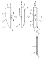
- FIG. 2 is an exploded explanatory view of the animal toilet 1.
- the animal toilet 1 is installed and used on, for example, an indoor floor and has a front-rear direction, a left-right direction, and a height direction.
- the animal toilet 1 has a longitudinal direction in the front-rear direction and a short direction in the left-right direction.
- the front-back direction, the left-right direction, and the height direction are directions orthogonal to each other.
- the installation surface side of the animal toilet 1 in the height direction is defined as the downward direction, and the opposite side is defined as the upward direction.
- the animal toilet 1 is composed of four members: an upper container 2, a tray 3, a cover 4, and a lower container 5.
- the upper container 2, the tray 3, the cover 4, and the lower container 5 are formed by molding a resin such as polyethylene (PE), polypropylene (PP), or polyethylene terephthalate (PET).
- PE polyethylene
- PP polypropylene
- PET polyethylene terephthalate
- the assembling method of the animal toilet 1 is as follows. As shown in FIG. 2, the upper container 2 is assembled from above the lower container 5. And the cover 4 is assembled
- the tray 3 is slidable in the front-rear direction with respect to the lower container 5 and is accommodated in the lower container 5. In the following description, the direction in which the tray 3 is accommodated in the lower container 5 among the front and rear directions is the rear direction, and the direction in which the tray 3 is pulled out from the lower container 5 is the front direction.
- the upper container 2 is a box-shaped member having an upper opening, a bottom surface 22 provided with a plurality of holes 210 through which urine passes, a side wall portion 23 erected upward from the periphery of the bottom surface 22, and a side wall And an edge 24 formed by folding the upper end of the portion 23 downward.
- the plurality of holes 210 constitute the urine passage part 21, and the excrement disposal material is installed on the urine passage part 21.
- the edge portion 24 is formed with a notch 240 at the center in the front-rear direction and at the position facing the left-right direction.
- the owner or the like can put his / her finger on the cutout portion 240, so that the upper container 2 can be easily assembled to the lower container 5 and the upper container 2 can be easily detached from the lower container 5, thereby improving workability.
- the notch 240 is not necessarily formed. In FIG. 2, only one of the two notches 240 is shown.
- the tray 3 is a member formed with a thin thickness in the height direction (vertical direction), and has an absorber installation part 31 having an upper opening and a handle 32 for taking in and out of the lower container 5. .
- the urine excreted from above the excrement disposal material passes through the plurality of holes 210 (urine passage part 21) of the upper container 2 and is installed in the absorber installation part 31 provided below the urine passage part 21. Absorbed by the absorbed body.
- the absorber is an absorbent sheet containing, for example, a polymer absorbent.
- the handles 32 are formed at both ends in the front-rear direction, and the tray 3 can be used upside down.
- the absorber installation part 31 is shown with the broken line.
- the cover 4 includes an opening 41 for animals to enter and exit, side walls 42 provided on both sides of the opening 41 in the left-right direction, a front wall 43 provided in front of the opening 41, and an opening. 41, a rear wall portion 44 provided behind 41, a side wall portion 42, a front wall portion 43, and an edge portion 45 provided at the lower end of the rear wall portion 44.
- the side wall part 42, the front wall part 43, the rear wall part 44, and the edge part 45 are integrally formed.
- the cover 4 does not have a bottom surface and penetrates in the height direction (vertical direction).
- the opening 41 is provided above the urine passage 21. As shown in FIG.1 and FIG.2, in this embodiment, it forms so that the upper end of the side wall part 42 may become low gradually toward the front from back.
- the side wall portion 42 and the rear wall portion 44 have a folded portion 4b whose upper end is folded inward (opening 41 side) and downward.
- the folding portion 4b is formed continuously from the portion facing the upper side of the front wall portion 43.
- the edge portion 45 has a cover-side fitting portion 451 extending downward at the center in the front-rear direction and the position facing the left-right direction.
- a hole 46 is formed in the cover side fitting portion 451. A specific configuration of the hole 46 will be described later.
- the lower container 5 is a box-like member that is open at the top, similar to the upper container 2, and includes a bottom surface 51, a side wall portion 52 erected upward from both lateral ends of the bottom surface 51, and a front end of the bottom surface 51.
- the front wall portion 54 erected upward, the rear wall portion 55 erected upward from the rear end of the bottom surface 51, and the upper ends of the side wall portion 52, the front wall portion 54, and the rear wall portion 55 downward.
- an edge 53 formed by folding a storage portion 57 for storing the tray 3 is formed inside the lower container 5.
- the accommodating part 57 is shown with the broken line.
- an entrance / exit 54 a for taking in and out the tray 3 is formed in the front wall 54. Further, as shown in FIG. 1, the front wall portion 54 is formed with a concave portion 54 b for easily placing the hand on the handle 32 of the tray 3.
- the edge portion 53 has a lower container side fitting portion 531 extending downward at the center in the front-rear direction and the position facing the left-right direction.
- the lower container side fitting portion 531 is provided with a protrusion 532 that is inserted into the hole 46 of the cover side fitting portion 451.
- the cover 4 and the lower container 5 are fitted by inserting the protrusion 532 of the lower container side fitting part 531 into the hole 46 of the cover side fitting part 451.
- protrusions 56 protruding upward are provided at positions facing each other in the left-right direction.
- these protrusions 56 are interposed in the space formed by folding the upper end of the upper container 2 when the edge 24 of the upper container 2 is formed, thereby lower container The horizontal movement of the upper container 2 with respect to 5 is restricted.
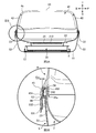
- FIG. 3A is a cross-sectional view taken along the line IIIA-IIIA of FIG. 1, and FIG. 3B is an enlarged view of a portion IIIB of FIG. 3A.
- 4A and 4B are enlarged views of the periphery of the fitting portion between the cover 4 and the lower container 5, FIG. 4A shows a state before the cover 4 and the lower container 5 are fitted, and FIG. The state after 4 and the lower container 5 are fitted is shown.
- the edge 24 of the upper container 2 is indicated by a broken line.
- the edge 24 of the upper container 2 is formed to be inclined so as to spread outward from the upper side to the lower side.
- the edge 24 is located on the edge 53 of the lower container 5. That is, the edge 24 of the upper container 2 and the edge 53 of the lower container 5 are located side by side along the height direction.
- the edge 24 is in contact with the upper end of the edge 53 of the lower container 5 at a portion other than the portion where the notch 240 is provided.
- the protrusion 532 provided on the edge 53 (lower container side fitting portion 531) of the lower container 5 protrudes outward from the edge 24 of the upper container 2. Further, the edge portion 451 of the cover 4 is located outside the edge portion 24 of the upper container 2. In other words, the edge 24 of the upper container 2 is located inside the edge 451 of the cover 4.
- the cover 4 has an extended portion 452 that extends downward and is formed along the edge 451 inside the edge 451, and the edge 451 and the extended portion 452.
- the edge 24 of the upper container 2 is interposed in a space 45a formed between the two.
- the fitting between the cover 4 and the lower container 5 is such that the protrusion 532 on the lower container 5 side located outside the edge 24 of the upper container 2 in the left-right direction is outside the edge 24 of the upper container 2. This is performed by inserting the hole 46 provided in the edge 45 (cover-side fitting portion 451) of the cover 4 that is positioned. Further, the hole 46 and the protrusion 532 are provided below the edge 24 of the upper container 2. Thereby, it becomes easy to visually recognize the fitting state of the cover 4 and the lower container 5 from the outside, and the problem that the animal toilet 1 is lifted in an incomplete fitting state can be avoided.
- the protrusion 532 protrudes outward from the edge 24 of the upper container 2, and the hole 46 and the protrusion 532 which are fitting portions are provided below the edge 24 of the upper container 2.
- the protrusion 532 protrudes outward from the edge 53 of the lower container 5 in the left-right direction. This makes it easy to confirm the position of the protrusion 532 when the cover 4 is assembled to the upper container 2 and the lower container 5, and the fitting state between the cover 4 and the lower container 5 is also visually recognized from the outside. It becomes easy to do. Note that the protrusion 532 does not necessarily have to protrude outward from the edge 53 of the lower container 5, and only needs to protrude outward from at least the upper container 2.
- the length of the upper container 2 in the left-right direction is smaller than the length of the lower container 5 in the left-right direction at the position where the protrusion 532 is provided in the front-rear direction.
- the outer end of the edge 24 of the upper container 2 is positioned inward in the left-right direction by Gw with respect to the outer end of the edge 53 of the lower container 5.
- the edge 24 of the upper container 2 is inclined so as to fall inward in the left-right direction as it goes from below to above, and the notch 240 is provided at the position where the protrusion 532 is provided.
- the length of the upper container in the left-right direction is smaller than the length of the lower container 5 in the left-right direction at the position where the protrusion 532 is provided.
- the horizontal length of the upper container at the position where the protrusion 532 is provided does not have to be smaller than the horizontal length of the lower container 5. It is also possible to cope with this by changing the angle of inclination (inclination angle) of the edge 24 of the container 2 inward in the left-right direction. Further, the relationship between the length of the upper container 2 in the left-right direction and the length of the lower container 5 in the left-right direction is not necessarily limited to this, and at least the edge 24 of the upper container 2 is positioned on the edge 53 of the lower container 5. If you do.
- the cross-sectional shape of the protrusion 532 is an ellipse, and the size W in the front-rear direction of the ellipse is larger than the size H in the height direction. That is, the protrusion 532 has an elliptical shape that is elongated in the front-rear direction.
- the force is most concentrated on the portion of the protrusion 532 in the front-rear direction. Then, since the area
- the curvature of the upper part 532a of the ellipse is larger than the curvature of the lower part 532b. That is, the lower portion 532b is flat compared to the upper portion 532a. In other words, the upper portion 532a is formed in an arc shape compared to the lower portion 532b. For this reason, when the animal toilet 1 is lifted upward with the fitting part (cover side fitting part 451), the curvature of the lower part 532b where the force is most concentrated is smaller than the curvature of the upper part 532a. The contact area with the cover 4 becomes wider, and the force can be received uniformly.
- the shape of the protrusion 532 is not necessarily limited to this, and is a shape that can be inserted into the hole 46 provided in the cover side fitting portion 451, and the fitting state between the cover 4 and the lower container 5 can be maintained. What is necessary is just to have such a shape.
- the hole 46 is connected to a pair of notches 47 as shown in FIG. 4A. For this reason, since the hole 46 is easily bent when the protrusion 532 is inserted into the hole 46, the protrusion 532 can be easily inserted into the hole 46.
- the notches 47 do not necessarily need to be a pair, and may be connected to at least one notch 47 so that the hole 46 is easily bent when the protrusion 532 is inserted into the hole 46.
- the hole 46 does not necessarily need to be connected to the notch 47, and it is only necessary that the hole 4 into which the protrusion 532 can be inserted is provided in the cover 4.
- the outline of the protrusion 532 represents the outline of the cat's face, and a pair of cuts provided at the upper part of the hole 46.
- a notch 47 represents the cat's ear. That is, the face and ear of the animal are formed by the hole 46 and the pair of notches 47 in the cover 4, and the protrusion 532 that becomes the animal's face is fitted into the hole 46.
- the fitting state between the hole 46 and the protrusion 532 can be visually recognized by the shape of the animal, and the fitting state between the cover 4 and the lower container 5 can be confirmed more easily.
- the pair of notches 47 has an upper end 47 a located below the edge 24 of the upper container 2. For this reason, when the pair of notches 47 are viewed in the left-right direction in a state where the cover 4 and the lower container 5 are fitted, the upper container 2 is not seen through the pair of notches 47.
- the fitting state with the protrusion 532 becomes easy to visually recognize. In the present embodiment, only the upper container 2 has a different color, so that the fitting state between the hole 46 and the protrusion 532 is more easily understood. Note that the upper ends 47 a of the pair of notches 47 are not necessarily located below the edge 24 of the upper container 2.
- the animal toilet 1 is provided with the absorbent body installation part 31 for installing the absorbent body that absorbs urine that has passed through the plurality of holes 210 (urine passage part 21) of the upper container 2 in the tray 3.
- the absorber installation portion 31 may be provided in the lower container 5 and can be appropriately changed according to the application.
Landscapes
- Life Sciences & Earth Sciences (AREA)
- Environmental Sciences (AREA)
- Animal Husbandry (AREA)
- Biodiversity & Conservation Biology (AREA)
- Zoology (AREA)
- Housing For Livestock And Birds (AREA)
Abstract
動物用トイレ1は、前後方向、左右方向、及び高さ方向を備え、動物が出入りするための開口部41を備えたカバー4と、尿が通過する複数の穴210が設けられた上容器2と、下容器5とを有し、上容器2の縁部24は、下容器5の縁部53上に位置し、カバー4の縁部45は、上容器2の縁部24よりも外側に位置し、上容器2の縁部24よりも下方において、カバー4の縁部45に穴46が設けられており、上容器2の縁部24よりも下方において、下容器5に、穴46に挿入される突部532が設けられており、左右方向において、突部532は、上容器2よりも外側に突出している。
Description
本発明は、動物用トイレに関する。
従来、動物用トイレとして、特許文献1に示すように、室内で飼育される猫等の動物が使用するものが知られている。この動物用トイレは、動物が出入りするための開口及び尿が通過する液通過性の底面部を有する上部容器と、底面部を通過した尿を吸収する吸液シートを配置する配置容器を収容する収容部を有する下部容器と、動物の出入り方向を規制するためのカバーとを備えている。上部容器の底面部における尿通過領域には、粒状物が撒設される。
カバーは、略矩形状の周縁枠の三方に壁体が立設されると共に、残り一方に動物の出入り口を有する平面視略コ字状箱体であり、上部容器に着脱自在に取り付けられる。周縁枠は、上部容器の上端周縁と略同じ大きさであり、その側部には上部容器の上端部に嵌合するための嵌合爪が内側に突出して形成されている。
特許文献1に記載された動物用トイレでは、カバー側に設けられた内側に突出する嵌合爪を上部容器の上端部に引っ掛けることによってカバーと上部容器との嵌合を行うため、カバーと上部容器との嵌合状態の確認が外部からしづらかった。
本発明は、上記のような問題に鑑みてなされたものであって、その目的とするところは、外部から嵌合状態を確認しやすい動物用トイレを提供することにある。
上記目的を達成するための主たる発明は、前後方向、左右方向、及び高さ方向を備え、動物が出入りするための開口部を備えたカバーと、尿が通過する複数の穴が設けられた上容器と、下容器とを有し、前記上容器の縁部は、前記下容器の縁部上に位置し、前記カバーの縁部は、前記上容器の前記縁部よりも外側に位置し、前記上容器の前記縁部よりも下方において、前記カバーの前記縁部に穴が設けられており、前記上容器の前記縁部よりも下方において、前記下容器に、前記穴に挿入される突部が設けられており、前記左右方向において、前記突部は、前記上容器よりも外側に突出していることを特徴とする動物用トイレである。本発明の他の特徴については、本明細書及び添付図面の記載により明らかにする。
本発明によれば、外部から嵌合状態を確認しやすくなる。
本明細書及び添付図面の記載により、少なくとも以下の事項が明らかとなる。
前後方向、左右方向、及び高さ方向を備え、動物が出入りするための開口部を備えたカバーと、尿が通過する複数の穴が設けられた上容器と、下容器とを有し、前記上容器の縁部は、前記下容器の縁部上に位置し、前記カバーの縁部は、前記上容器の前記縁部よりも外側に位置し、前記上容器の前記縁部よりも下方において、前記カバーの前記縁部に穴が設けられており、前記上容器の前記縁部よりも下方において、前記下容器に、前記穴に挿入される突部が設けられており、前記左右方向において、前記突部は、前記上容器よりも外側に突出している動物用トイレが明らかとなる。これにより、前記カバーと前記下容器との嵌合状態が外部から視認することが容易になる。
かかる動物用トイレであって、前記前後方向における、前記突部の設けられている位置において、前記上容器の前記左右方向の長さが、前記下容器の前記左右方向の長さよりも小さいことが望ましい。これにより、前記カバーを取り外す際に前記カバーの前記縁部が前記上容器の前記縁部に引っ掛かってしまうことを抑制できる。
かかる動物用トイレであって、前記前後方向における、前記突部の設けられている位置において、前記上容器の前記縁部に切り欠き部が設けられていることが望ましい。これにより、前記切り欠き部に指等を掛けることが可能となるため、前記上容器を前記下容器から取り外しやすくなる。
かかる動物用トイレであって、前記左右方向において、前記突部は、前記下容器の前記縁部から外側に突出していることが望ましい。これにより、前記カバーを組み付ける際に前記突部の位置を確認することが容易になると共に、前記カバーと前記下容器との嵌合状態の視認もよりしやすくなる。
かかる動物用トイレであって、前記突部の断面形状は、楕円であり、前記楕円の前記前後方向の大きさは、前記楕円の前記高さ方向の大きさよりも大きいことが望ましい。これにより、嵌合部分を持って上方向に持ち上げる際に、力がもっとも集中する前記突部の前記前後方向の領域が増えるため、前記穴から前記突部が外れてしまうことを抑制することができる。
かかる動物用トイレであって、前記楕円の上部の曲率は、前記楕円の下部の曲率よりも大きいことが望ましい。これにより、前記楕円の前記下部において前記カバーとの接触領域が広くなり、嵌合部分を持って上方向に持ち上げた際にかかる力を均一に受けることができる。
かかる動物用トイレであって、前記穴は、切り欠きと繋がっていることが望ましい。これにより、前記穴に前記突部を挿入する際において前記穴が撓みやすくなるため、前記突部を前記穴に挿入しやすい。
かかる動物用トイレであって、前記切り欠きは、前記穴の上部に設けられ、前記切り欠きの上端は、前記上容器の前記縁部よりも下方に位置することが望ましい。これにより、前記カバーと前記下容器とを嵌合した状態において左右方向に前記一対の切り欠きを見た場合に、前記一対の切り欠きを介して前記上容器が見えることがないため、前記穴と前記突部との嵌合状態がより分かりやすくなる。
かかる動物用トイレであって、前記穴に、前記突部が挿入された状態において、前記突部の輪郭が動物の顔の輪郭を表し、一対の前記切り欠きが、前記動物の耳を表すことが望ましい。これにより、前記穴と前記突部との嵌合状態を動物の形状によって視認することができるため、前記カバーと前記下容器との嵌合状態の確認がより容易になる。
===実施形態===
本発明の実施形態にかかる動物用トイレは、例えば室内で飼われる猫等の動物が使用するものである。本明細書中における「動物」とは、猫、犬、ウサギ、ハムスター等のいわゆるペットやトラ、ライオンの赤ちゃん等も含む。
本発明の実施形態にかかる動物用トイレは、例えば室内で飼われる猫等の動物が使用するものである。本明細書中における「動物」とは、猫、犬、ウサギ、ハムスター等のいわゆるペットやトラ、ライオンの赤ちゃん等も含む。
例えば、動物が猫である場合における動物用トイレの使用方法としては次の通りである。猫が動物用トイレ内に入り、例えば猫砂やサンド等と呼ばれる排泄物処理材の上から排尿や排便をする。その後、猫は排泄物処理材を足でかいて排泄物を隠す。飼い主等は、排泄物で汚れた部分の排泄物処理材を排泄物と共に動物用トイレ内から取り除き、取り除いた分だけ新しい排泄物処理材を補充する。
<動物用トイレ1の全体構成>
動物用トイレ1の全体構成について、図1及び図2を参照して説明する。
動物用トイレ1の全体構成について、図1及び図2を参照して説明する。
図1は、本発明の実施形態に係る動物用トイレ1の一構成例を示す斜視図である。図2は、動物用トイレ1の分解説明図である。
動物用トイレ1は、例えば室内の床等の上に設置されて使用されるものであり、前後方向、左右方向、及び高さ方向を備える。本実施形態では、動物用トイレ1は、前後方向に長手方向を有し、左右方向に短手方向を有する。なお、前後方向、左右方向、及び高さ方向は、互いに直交する方向である。以下の説明において、高さ方向のうち動物用トイレ1の設置面側を下方向とし、その反対側を上方向とする。
動物用トイレ1は、上容器2、トレイ3、カバー4、及び下容器5の4つの部材から構成されている。上容器2、トレイ3、カバー4、及び下容器5は、例えばポリエチレン(PE)、ポリプロピレン(PP)、ポリエチレンテレフタレート(PET)等の樹脂を成形加工してなる。
動物用トイレ1の組み付け方法は次の通りである。図2に示すように、下容器5の上方から上容器2を組み付ける。そして、上容器2が組み付けられた下容器5に対して上容器2の上方からカバー4を組み付ける。トレイ3は、下容器5に対して前後方向にスライド可能であり、下容器5内に収容される。以下の説明において、前後方向のうちトレイ3を下容器5内に収容する方向を後方向とし、トレイ3を下容器5内から引き出す方向を前方向とする。
上容器2は、上方が開口した箱状の部材であり、尿が通過する複数の穴210が設けられた底面22と、底面22の周縁から上方に向かって立設した側壁部23と、側壁部23の上方端を下方に向かって折り返して形成された縁部24とを有している。複数の穴210は尿通過部21を構成し、当該尿通過部21上には排泄物処理材が設置される。
図2に示すように、縁部24には、前後方向の中央かつ左右方向に対向する位置に、切り欠き部240がそれぞれ形成されている。これにより、飼い主等が切り欠き部240に指を掛けることが可能となるため、上容器2を下容器5に組み付けたり、上容器2を下容器5から取り外したりしやすくなり作業性が向上する。なお、上容器2において、必ずしも切り欠き部240が形成されている必要はない。図2では、2つの切り欠き部240のうち一方の切り欠き部240のみを示している。
トレイ3は、高さ方向(上下方向)の厚さが薄く形成された部材であり、上方が開口した吸収体設置部31と、下容器5から出し入れするための取っ手32とを有している。排泄物処理材の上から排泄された尿は、上容器2の複数の穴210(尿通過部21)を通過して、尿通過部21よりも下方に設けられた吸収体設置部31に設置された吸収体に吸収される。吸収体は、例えば高分子吸収材を含有した吸収シートである。
取っ手32は、図2に示すように、前後方向の両端にそれぞれ形成されており、トレイ3を前後逆さまにして使用することも可能である。なお、図2において吸収体設置部31を破線で示している。
カバー4は、動物が出入りするための開口部41と、開口部41の左右方向の両側にそれぞれ設けられた側壁部42と、開口部41の前方に設けられた前方壁部43と、開口部41の後方に設けられた後方壁部44と、側壁部42、前方壁部43、及び後方壁部44の下端に設けられた縁部45とを有している。本実施形態では、側壁部42、前方壁部43、後方壁部44、及び縁部45は一体に形成されている。また、カバー4は、底面を有しておらず、高さ方向(上下方向)に貫通している。
開口部41は、尿通過部21よりも上方に設けられている。図1及び図2に示すように、本実施形態では、側壁部42の上端が後方から前方に向かって次第に低くなるように形成されている。
図1に示すように、側壁部42及び後方壁部44は、上端が内側(開口部41側)かつ下方向に折り込まれた折り込み部4bを有している。当該折り込み部4bは、前方壁部43の上方に面した部分から連続して形成されている。
縁部45は、下方に向かって延出するカバー側嵌合部451を前後方向の中央かつ左右方向に対向する位置にそれぞれ有している。カバー側嵌合部451には、穴46が形成されている。なお、この穴46の具体的な構成については、後述することとする。
下容器5は、上容器2と同様に上方が開口した箱状の部材であり、底面51と、底面51の左右方向の両端から上方に立設した側壁部52と、底面51の前方端から上方に立設した前方壁部54と、底面51の後方端から上方に立設した後方壁部55と、側壁部52、前方壁部54、及び後方壁部55の上方端を下方に向かって折り返して形成された縁部53とを有している。また、下容器5の内部には、トレイ3を収容するための収容部57が形成されている。なお、図2において、収容部57を破線で示している。
前方壁部54には、図2に示すように、収容部57に対してトレイ3を出し入れするための出入り口54aが形成されている。また、図1に示すように、前方壁部54には、トレイ3の取っ手32に手を掛けやすくするための凹部54bが形成されている。
縁部53は、下方に向かって延出する下容器側嵌合部531を前後方向の中央かつ左右方向に対向する位置にそれぞれ有している。下容器側嵌合部531には、カバー側嵌合部451の穴46に挿入される突部532が設けられている。カバー4と下容器5との嵌合は、下容器側嵌合部531の突部532をカバー側嵌合部451の穴46に挿入することによって行われる。
また、縁部53の上方端には、上方に向かって突出した2つの突起56がそれぞれ左右方向に対向する位置に設けられている。上容器2を下容器5に組み付けた際、これらの突起56が上容器2の縁部24の形成時に上容器2の上方端を折り返すことによって形成された空間内に介在することにより、下容器5に対する上容器2の左右方向の移動が規制される。
<カバー4と下容器5との嵌合部分周辺の構成>
次に、カバー4と下容器5との嵌合部分周辺の構成について、図3A及び図3Bならびに図4A及び図4Bを参照して説明する。
次に、カバー4と下容器5との嵌合部分周辺の構成について、図3A及び図3Bならびに図4A及び図4Bを参照して説明する。
図3Aは、図1のIIIA-IIIA線断面図であり、図3Bは、図3AのIIIB部拡大図である。図4A及び図4Bは、カバー4と下容器5との嵌合部分周辺の拡大図であり、図4Aは、カバー4と下容器5との嵌合前の状態を示し、図4Bは、カバー4と下容器5との嵌合後の状態を示している。なお、図4Bにおいて、上容器2の縁部24を破線で示している。
(上容器2、カバー4、及び下容器5の位置関係について)
まず、上容器2、カバー4、及び下容器5の位置関係について、図3A、図3B、及び図4Aを参照して説明する。
まず、上容器2、カバー4、及び下容器5の位置関係について、図3A、図3B、及び図4Aを参照して説明する。
図3Bに示すように、上容器2の縁部24は、上方から下方に向かって外側に広がるように傾斜して形成されている。また、縁部24は下容器5の縁部53上に位置している。つまり、上容器2の縁部24と下容器5の縁部53とは、高さ方向に沿って並んで位置している。本実施形態では、図4Aに示すように、縁部24は、切り欠き部240が設けられた部分以外の部分において、下端が下容器5の縁部53の上端に接触している。
下容器5の縁部53(下容器側嵌合部531)に設けられた突部532は、上容器2の縁部24よりも外側に突出している。また、カバー4の縁部451は、上容器2の縁部24よりも外側に位置している。換言すれば、上容器2の縁部24はカバー4の縁部451よりも内側に位置している。本実施形態では、カバー4は、縁部451の内側に、下方に向かって延出しかつ縁部451に沿って形成された延出部452を有しており、縁部451と延出部452との間に形成された空間45a内に上容器2の縁部24が介在している。
カバー4と下容器5との嵌合は、左右方向において上容器2の縁部24よりも外側に位置している下容器5側の突部532を上容器2の縁部24よりも外側に位置しているカバー4の縁部45(カバー側嵌合部451)に設けられた穴46に挿入することにより行う。また、穴46及び突部532は、上容器2の縁部24よりも下方に設けられている。これにより、カバー4と下容器5との嵌合状態を外部から視認することが容易となり、不完全な嵌合状態のまま動物用トイレ1を持ち上げてしまうといった問題を回避することができる。
また、左右方向において上容器2の縁部24よりも外側に位置しているカバー4の縁部451に設けられた穴46に対して、下容器5の縁部53に設けられた突部532を左右方向内側から挿入することによりカバー4と下容器5とを嵌合させる。これにより、例えば内側に突出する爪等がカバー4側に設けられている場合のように、爪等が上容器2の縁部24に引っ掛かってしまい上容器2が下容器5から外れてしまうといった事態を回避することができる。
またさらに、動物が排尿する尿通過部21が設けられた上容器2の縁部24がカバー4の縁部451よりも内側に位置すると共に、カバー4との嵌合部分である下容器5の突部532が上容器2の縁部24よりも外側に突出し、嵌合部分である穴46及び突部532が上容器2の縁部24よりも下方に設けられている。これにより、上容器2の縁部24に近い場所で動物が排尿してしまった場合でも、嵌合部分を介して尿が動物用トイレ1の外部に漏れ出してしまうといった可能性を低減することができる。
本実施形態では、左右方向において、突部532は、下容器5の縁部53から外側に突出している。これにより、カバー4を上容器2及び下容器5に対して組み付ける際に突部532の位置を確認することが容易になると共に、カバー4と下容器5との嵌合状態も外部からより視認しやすくなる。なお、突部532は、必ずしも下容器5の縁部53から外側に突出している必要はなく、少なくとも上容器2よりも外側に突出していればよい。
前後方向における、突部532の設けられている位置において、上容器2の左右方向の長さは下容器5の左右方向の長さよりも小さい。具体的には、図3Bに示すように、上容器2の縁部24の外端は下容器5の縁部53の外端よりもGwだけ左右方向内側に位置している。本実施形態では、上容器2の縁部24が下方から上方に向かうに連れて左右方向内側に倒れるように傾斜しており、かつ突部532の設けられている位置に切り欠き部240が設けられていることにより、突部532の設けられている位置において上容器の左右方向の長さが下容器5の左右方向の長さよりも小さくなるように形成している。これにより、カバー4を取り外す際等に、カバー4の縁部45が上容器2の縁部24に引っ掛かってしまうことを抑制することができる。
なお、切り欠き部240を形成することにより、突部532の設けられている位置において上容器の左右方向の長さが下容器5の左右方向の長さよりも小さくなるようにせずとも、例えば上容器2の縁部24の左右方向内側への倒れ角(傾斜角)を変更することにより対応することも可能である。また、上容器2の左右方向の長さと下容器5の左右方向の長さとの関係は必ずしもこれに限る必要はなく、少なくとも上容器2の縁部24が下容器5の縁部53上に位置していればよい。
(下容器5の突部532の構成)
次に、下容器5の突部532の具体的な形状等について、図4Aを参照して説明する。
次に、下容器5の突部532の具体的な形状等について、図4Aを参照して説明する。
突部532の断面形状は楕円であり、当該楕円の前後方向の大きさWは高さ方向の大きさHよりも大きい。すなわち、突部532は、前後方向に細長い楕円形状を有している。ここで、嵌合部分(カバー側嵌合部451)を持って動物用トイレ1を上方向に持ち上げることを考えた場合、突部532の前後方向に亘る部分に力がもっとも集中する。そこで、突部532の前後方向の大きさWを大きくすることにより力を受ける領域が増えるため、穴46から突部532が外れてしまうことを抑制することができる。
さらに、当該楕円(突部532)の上部532aの曲率は、下部532bの曲率よりも大きい。すなわち、下部532bは上部532aに比べて平坦であり、換言すれば、上部532aは下部532bに比べて円弧状に形成されている。このため、嵌合部分(カバー側嵌合部451)を持って動物用トイレ1を上方向に持ち上げた場合に力がもっとも集中する下部532bの曲率が上部532aの曲率よりも小さいため、下部532bにおけるカバー4との接触領域が広くなり、力を均一に受けることが可能となる。
なお、突部532の形状は必ずしもこれに限る必要はなく、カバー側嵌合部451に設けられた穴46に挿入可能な形状であり、カバー4と下容器5との嵌合状態が維持できるような形状を有していればよい。
(カバー4の穴46の構成)
次に、カバー4の穴46の具体的な形状等について、図4A及び図4Bを参照して説明する。
次に、カバー4の穴46の具体的な形状等について、図4A及び図4Bを参照して説明する。
穴46は、図4Aに示すように、一対の切り欠き47とつながっている。このため、穴46に突部532を挿入する際に穴46が撓みやすくなるため、突部532を穴46に挿入しやすくなる。なお、切り欠き47は、必ずしも一対である必要はなく、少なくとも1つの切り欠き47とつながり、突部532を穴46に挿入する際に穴46が撓みやすくなればよい。また、必ずしも穴46は切り欠き47とつながっている必要はなく、少なくとも突部532が挿入可能な穴46がカバー4に設けられていればよい。
本実施形態では、図4Bに示すように、穴46に突部532が挿入された状態において、突部532の輪郭が猫の顔の輪郭を表し、穴46の上部に設けられた一対の切り欠き47が猫の耳を表している。つまり、カバー4の穴46及び一対の切り欠き47によって動物の顔及び耳が形作られており、そこに動物の顔となる突部532が穴46に嵌合される。これによって、穴46と突部532との嵌合状態を動物の形状によって視認することが可能となり、カバー4と下容器5との嵌合状態の確認がより容易になる。なお、カバー4と下容器5との嵌合状態を確認するにあたり必ずしも動物の形状を表す必要はなく、一目見て嵌合状態が確認できる形状であればよい。
図4Bに示すように、一対の切り欠き47は、上端47aが上容器2の縁部24よりも下方に位置している。このため、カバー4と下容器5とを嵌合した状態において左右方向に一対の切り欠き47を見た場合に一対の切り欠き47を介して上容器2が見えることがないため、穴46と突部532との嵌合状態が視認しやすくなる。本実施形態では、上容器2だけが異なる色を有することによって、穴46と突部532との嵌合状態がより分かりやすくなっている。なお、一対の切り欠き47の上端47aは必ずしも上容器2の縁部24よりも下方に位置している必要はない。
===その他===
上記の実施形態は、本発明の理解を容易にするためのものであり、本発明を限定して解釈するためのものではない。本発明は、その趣旨を逸脱することなく、変更、改良され得ると共に、本発明にはその等価物が含まれることは言うまでもない。
上記の実施形態は、本発明の理解を容易にするためのものであり、本発明を限定して解釈するためのものではない。本発明は、その趣旨を逸脱することなく、変更、改良され得ると共に、本発明にはその等価物が含まれることは言うまでもない。
上記の実施形態では、動物用トイレ1は、上容器2の複数の穴210(尿通過部21)を通過した尿を吸収する吸収体を設置するための吸収体設置部31をトレイ3に設けていたが、これに限らず、例えば下容器5に吸収体設置部31を設けてもよく、用途に応じて適宜変更することが可能である。
1…動物用トイレ
2…上容器
4…カバー
5…下容器
24,45,53…縁部
46…穴
47…切り欠き
47a…上端
240…切り欠き部
532…突部
2…上容器
4…カバー
5…下容器
24,45,53…縁部
46…穴
47…切り欠き
47a…上端
240…切り欠き部
532…突部
Claims (9)
- 前後方向、左右方向、及び高さ方向を備え、
動物が出入りするための開口部を備えたカバーと、尿が通過する複数の穴が設けられた上容器と、下容器とを有し、
前記上容器の縁部は、前記下容器の縁部上に位置し、
前記カバーの縁部は、前記上容器の前記縁部よりも外側に位置し、
前記上容器の前記縁部よりも下方において、前記カバーの前記縁部に穴が設けられており、
前記上容器の前記縁部よりも下方において、前記下容器に、前記穴に挿入される突部が設けられており、
前記左右方向において、前記突部は、前記上容器よりも外側に突出していることを特徴とする動物用トイレ。 - 請求項1に記載の動物用トイレであって、
前記前後方向における、前記突部の設けられている位置において、前記上容器の前記左右方向の長さが、前記下容器の前記左右方向の長さよりも小さいことを特徴とする動物用トイレ。 - 請求項2に記載の動物用トイレであって、
前記前後方向における、前記突部の設けられている位置において、前記上容器の前記縁部に切り欠き部が設けられていることを特徴とする動物用トイレ。 - 請求項1~3のいずれか1項に記載の動物用トイレであって、
前記左右方向において、前記突部は、前記下容器の前記縁部から外側に突出していることを特徴とする動物用トイレ。 - 請求項1~4のいずれか1項に記載の動物用トイレであって、
前記突部の断面形状は、楕円であり、
前記楕円の前記前後方向の大きさは、前記楕円の前記高さ方向の大きさよりも大きいことを特徴とする動物用トイレ。 - 請求項5に記載の動物用トイレであって、
前記楕円の上部の曲率は、前記楕円の下部の曲率よりも大きいことを特徴とする動物用トイレ。 - 請求項1~6のいずれか1項に記載の動物用トイレであって、
前記穴は、切り欠きと繋がっていることを特徴とする動物用トイレ。 - 請求項7に記載の動物用トイレであって、
前記切り欠きは、前記穴の上部に設けられ、
前記切り欠きの上端は、前記上容器の前記縁部よりも下方に位置することを特徴とする動物用トイレ。 - 請求項7又は8に記載の動物用トイレであって、
前記穴に、前記突部が挿入された状態において、
前記突部の輪郭が動物の顔の輪郭を表し、
一対の前記切り欠きが、前記動物の耳を表すことを特徴とする動物用トイレ。
Applications Claiming Priority (2)
| Application Number | Priority Date | Filing Date | Title |
|---|---|---|---|
| JP2015040205A JP6389778B2 (ja) | 2015-03-02 | 2015-03-02 | 動物用トイレ |
| JP2015-040205 | 2015-03-02 |
Publications (1)
| Publication Number | Publication Date |
|---|---|
| WO2016139963A1 true WO2016139963A1 (ja) | 2016-09-09 |
Family
ID=56843454
Family Applications (1)
| Application Number | Title | Priority Date | Filing Date |
|---|---|---|---|
| PCT/JP2016/050234 Ceased WO2016139963A1 (ja) | 2015-03-02 | 2016-01-06 | 動物用トイレ |
Country Status (3)
| Country | Link |
|---|---|
| JP (1) | JP6389778B2 (ja) |
| TW (1) | TWI681712B (ja) |
| WO (1) | WO2016139963A1 (ja) |
Cited By (1)
| Publication number | Priority date | Publication date | Assignee | Title |
|---|---|---|---|---|
| JP2021078412A (ja) * | 2019-11-19 | 2021-05-27 | 株式会社ペティオ | ペット用トイレ |
Families Citing this family (1)
| Publication number | Priority date | Publication date | Assignee | Title |
|---|---|---|---|---|
| JP7538713B2 (ja) * | 2020-12-25 | 2024-08-22 | エステー株式会社 | ペット用トイレ |
Citations (2)
| Publication number | Priority date | Publication date | Assignee | Title |
|---|---|---|---|---|
| JP2009011181A (ja) * | 2007-06-29 | 2009-01-22 | Unicharm Petcare Corp | 動物用トイレ |
| JP2013017446A (ja) * | 2011-07-13 | 2013-01-31 | Unicharm Corp | 動物用便器 |
Family Cites Families (2)
| Publication number | Priority date | Publication date | Assignee | Title |
|---|---|---|---|---|
| CN203814335U (zh) * | 2014-01-07 | 2014-09-10 | 张国强 | 猫厕 |
| TWM487624U (zh) * | 2014-05-26 | 2014-10-11 | San Lin Color Printing Co Ltd | 組合式貓屋結構 |
-
2015
- 2015-03-02 JP JP2015040205A patent/JP6389778B2/ja active Active
-
2016
- 2016-01-06 WO PCT/JP2016/050234 patent/WO2016139963A1/ja not_active Ceased
- 2016-02-22 TW TW105105130A patent/TWI681712B/zh active
Patent Citations (2)
| Publication number | Priority date | Publication date | Assignee | Title |
|---|---|---|---|---|
| JP2009011181A (ja) * | 2007-06-29 | 2009-01-22 | Unicharm Petcare Corp | 動物用トイレ |
| JP2013017446A (ja) * | 2011-07-13 | 2013-01-31 | Unicharm Corp | 動物用便器 |
Cited By (2)
| Publication number | Priority date | Publication date | Assignee | Title |
|---|---|---|---|---|
| JP2021078412A (ja) * | 2019-11-19 | 2021-05-27 | 株式会社ペティオ | ペット用トイレ |
| JP7486772B2 (ja) | 2019-11-19 | 2024-05-20 | 株式会社ペティオ | ペット用トイレ |
Also Published As
| Publication number | Publication date |
|---|---|
| JP6389778B2 (ja) | 2018-09-12 |
| JP2016158563A (ja) | 2016-09-05 |
| TWI681712B (zh) | 2020-01-11 |
| TW201633908A (zh) | 2016-10-01 |
Similar Documents
| Publication | Publication Date | Title |
|---|---|---|
| CN107205360B (zh) | 动物用厕所 | |
| US11032998B2 (en) | Toilet for animal | |
| US8327802B2 (en) | Animal litter box | |
| CN107249314B (zh) | 动物用厕所 | |
| US8794186B2 (en) | Covered, enclosed, collapsible, shippable, disposable animal litter box | |
| AU2014275981B2 (en) | Litter box for animals | |
| JP7234033B2 (ja) | 動物用トイレ | |
| JP5768200B1 (ja) | 動物用トイレ | |
| US10154647B2 (en) | Toilet for animal | |
| TWI680711B (zh) | 動物用便器 | |
| US20160251134A1 (en) | Animal litter box package body | |
| JP6389778B2 (ja) | 動物用トイレ | |
| JP6387312B2 (ja) | 動物用トイレ | |
| JP4731632B2 (ja) | ペット用トイレ | |
| JP6491943B2 (ja) | 動物用トイレ | |
| JP6857913B2 (ja) | 小動物用トイレ | |
| TWI694766B (zh) | 動物用便器 | |
| JP6560084B2 (ja) | 猫用トイレ | |
| JP2023032151A (ja) | 動物用トイレ及び動物用トイレセット | |
| CZ22877U1 (cs) | Mobilní přepravní box pro chovatelské potřeby | |
| KR20240046517A (ko) | 동물용 화장실 및 동물용 화장실 세트 | |
| JP2024106280A (ja) | 小動物用排泄容器 | |
| JP2023032154A (ja) | 動物用トイレ及び動物用トイレセット |
Legal Events
| Date | Code | Title | Description |
|---|---|---|---|
| 121 | Ep: the epo has been informed by wipo that ep was designated in this application |
Ref document number: 16758659 Country of ref document: EP Kind code of ref document: A1 |
|
| NENP | Non-entry into the national phase |
Ref country code: DE |
|
| 122 | Ep: pct application non-entry in european phase |
Ref document number: 16758659 Country of ref document: EP Kind code of ref document: A1 |