WO2016139836A1 - 発電設備の運転計画策定システム及び発電設備の運転計画策定方法 - Google Patents
発電設備の運転計画策定システム及び発電設備の運転計画策定方法 Download PDFInfo
- Publication number
- WO2016139836A1 WO2016139836A1 PCT/JP2015/076991 JP2015076991W WO2016139836A1 WO 2016139836 A1 WO2016139836 A1 WO 2016139836A1 JP 2015076991 W JP2015076991 W JP 2015076991W WO 2016139836 A1 WO2016139836 A1 WO 2016139836A1
- Authority
- WO
- WIPO (PCT)
- Prior art keywords
- power
- power generation
- loss
- operation mode
- operation plan
- Prior art date
- Legal status (The legal status is an assumption and is not a legal conclusion. Google has not performed a legal analysis and makes no representation as to the accuracy of the status listed.)
- Ceased
Links
Images



Classifications
-
- G—PHYSICS
- G06—COMPUTING OR CALCULATING; COUNTING
- G06Q—INFORMATION AND COMMUNICATION TECHNOLOGY [ICT] SPECIALLY ADAPTED FOR ADMINISTRATIVE, COMMERCIAL, FINANCIAL, MANAGERIAL OR SUPERVISORY PURPOSES; SYSTEMS OR METHODS SPECIALLY ADAPTED FOR ADMINISTRATIVE, COMMERCIAL, FINANCIAL, MANAGERIAL OR SUPERVISORY PURPOSES, NOT OTHERWISE PROVIDED FOR
- G06Q50/00—Information and communication technology [ICT] specially adapted for implementation of business processes of specific business sectors, e.g. utilities or tourism
- G06Q50/06—Energy or water supply
-
- G—PHYSICS
- G05—CONTROLLING; REGULATING
- G05B—CONTROL OR REGULATING SYSTEMS IN GENERAL; FUNCTIONAL ELEMENTS OF SUCH SYSTEMS; MONITORING OR TESTING ARRANGEMENTS FOR SUCH SYSTEMS OR ELEMENTS
- G05B15/00—Systems controlled by a computer
- G05B15/02—Systems controlled by a computer electric
-
- G—PHYSICS
- G06—COMPUTING OR CALCULATING; COUNTING
- G06Q—INFORMATION AND COMMUNICATION TECHNOLOGY [ICT] SPECIALLY ADAPTED FOR ADMINISTRATIVE, COMMERCIAL, FINANCIAL, MANAGERIAL OR SUPERVISORY PURPOSES; SYSTEMS OR METHODS SPECIALLY ADAPTED FOR ADMINISTRATIVE, COMMERCIAL, FINANCIAL, MANAGERIAL OR SUPERVISORY PURPOSES, NOT OTHERWISE PROVIDED FOR
- G06Q10/00—Administration; Management
- G06Q10/04—Forecasting or optimisation specially adapted for administrative or management purposes, e.g. linear programming or "cutting stock problem"
-
- G—PHYSICS
- G06—COMPUTING OR CALCULATING; COUNTING
- G06Q—INFORMATION AND COMMUNICATION TECHNOLOGY [ICT] SPECIALLY ADAPTED FOR ADMINISTRATIVE, COMMERCIAL, FINANCIAL, MANAGERIAL OR SUPERVISORY PURPOSES; SYSTEMS OR METHODS SPECIALLY ADAPTED FOR ADMINISTRATIVE, COMMERCIAL, FINANCIAL, MANAGERIAL OR SUPERVISORY PURPOSES, NOT OTHERWISE PROVIDED FOR
- G06Q10/00—Administration; Management
- G06Q10/06—Resources, workflows, human or project management; Enterprise or organisation planning; Enterprise or organisation modelling
- G06Q10/063—Operations research, analysis or management
- G06Q10/0631—Resource planning, allocation, distributing or scheduling for enterprises or organisations
-
- G—PHYSICS
- G06—COMPUTING OR CALCULATING; COUNTING
- G06Q—INFORMATION AND COMMUNICATION TECHNOLOGY [ICT] SPECIALLY ADAPTED FOR ADMINISTRATIVE, COMMERCIAL, FINANCIAL, MANAGERIAL OR SUPERVISORY PURPOSES; SYSTEMS OR METHODS SPECIALLY ADAPTED FOR ADMINISTRATIVE, COMMERCIAL, FINANCIAL, MANAGERIAL OR SUPERVISORY PURPOSES, NOT OTHERWISE PROVIDED FOR
- G06Q30/00—Commerce
- G06Q30/02—Marketing; Price estimation or determination; Fundraising
- G06Q30/0201—Market modelling; Market analysis; Collecting market data
- G06Q30/0202—Market predictions or forecasting for commercial activities
-
- H—ELECTRICITY
- H02—GENERATION; CONVERSION OR DISTRIBUTION OF ELECTRIC POWER
- H02J—ELECTRIC POWER NETWORKS; CIRCUIT ARRANGEMENTS OR SYSTEMS FOR SUPPLYING OR DISTRIBUTING ELECTRIC POWER; SYSTEMS FOR STORING ELECTRIC ENERGY
- H02J3/00—Circuit arrangements for AC mains or AC distribution networks
- H02J3/003—Load forecast, e.g. methods or systems for forecasting future load demand
-
- H—ELECTRICITY
- H02—GENERATION; CONVERSION OR DISTRIBUTION OF ELECTRIC POWER
- H02J—ELECTRIC POWER NETWORKS; CIRCUIT ARRANGEMENTS OR SYSTEMS FOR SUPPLYING OR DISTRIBUTING ELECTRIC POWER; SYSTEMS FOR STORING ELECTRIC ENERGY
- H02J3/00—Circuit arrangements for AC mains or AC distribution networks
- H02J3/004—Generation forecast, e.g. methods or systems for forecasting future energy generation
-
- H—ELECTRICITY
- H02—GENERATION; CONVERSION OR DISTRIBUTION OF ELECTRIC POWER
- H02J—ELECTRIC POWER NETWORKS; CIRCUIT ARRANGEMENTS OR SYSTEMS FOR SUPPLYING OR DISTRIBUTING ELECTRIC POWER; SYSTEMS FOR STORING ELECTRIC ENERGY
- H02J3/00—Circuit arrangements for AC mains or AC distribution networks
- H02J3/008—Circuit arrangements for power supply or distribution technologies responsive to energy trading
-
- H—ELECTRICITY
- H02—GENERATION; CONVERSION OR DISTRIBUTION OF ELECTRIC POWER
- H02J—ELECTRIC POWER NETWORKS; CIRCUIT ARRANGEMENTS OR SYSTEMS FOR SUPPLYING OR DISTRIBUTING ELECTRIC POWER; SYSTEMS FOR STORING ELECTRIC ENERGY
- H02J2103/00—Details of circuit arrangements for mains or AC distribution networks
- H02J2103/30—Simulating, planning, modelling, reliability check or computer assisted design [CAD] of electric power networks
-
- Y—GENERAL TAGGING OF NEW TECHNOLOGICAL DEVELOPMENTS; GENERAL TAGGING OF CROSS-SECTIONAL TECHNOLOGIES SPANNING OVER SEVERAL SECTIONS OF THE IPC; TECHNICAL SUBJECTS COVERED BY FORMER USPC CROSS-REFERENCE ART COLLECTIONS [XRACs] AND DIGESTS
- Y02—TECHNOLOGIES OR APPLICATIONS FOR MITIGATION OR ADAPTATION AGAINST CLIMATE CHANGE
- Y02E—REDUCTION OF GREENHOUSE GAS [GHG] EMISSIONS, RELATED TO ENERGY GENERATION, TRANSMISSION OR DISTRIBUTION
- Y02E60/00—Enabling technologies; Technologies with a potential or indirect contribution to GHG emissions mitigation
-
- Y—GENERAL TAGGING OF NEW TECHNOLOGICAL DEVELOPMENTS; GENERAL TAGGING OF CROSS-SECTIONAL TECHNOLOGIES SPANNING OVER SEVERAL SECTIONS OF THE IPC; TECHNICAL SUBJECTS COVERED BY FORMER USPC CROSS-REFERENCE ART COLLECTIONS [XRACs] AND DIGESTS
- Y04—INFORMATION OR COMMUNICATION TECHNOLOGIES HAVING AN IMPACT ON OTHER TECHNOLOGY AREAS
- Y04S—SYSTEMS INTEGRATING TECHNOLOGIES RELATED TO POWER NETWORK OPERATION, COMMUNICATION OR INFORMATION TECHNOLOGIES FOR IMPROVING THE ELECTRICAL POWER GENERATION, TRANSMISSION, DISTRIBUTION, MANAGEMENT OR USAGE, i.e. SMART GRIDS
- Y04S10/00—Systems supporting electrical power generation, transmission or distribution
- Y04S10/50—Systems or methods supporting the power network operation or management, involving a certain degree of interaction with the load-side end user applications
-
- Y—GENERAL TAGGING OF NEW TECHNOLOGICAL DEVELOPMENTS; GENERAL TAGGING OF CROSS-SECTIONAL TECHNOLOGIES SPANNING OVER SEVERAL SECTIONS OF THE IPC; TECHNICAL SUBJECTS COVERED BY FORMER USPC CROSS-REFERENCE ART COLLECTIONS [XRACs] AND DIGESTS
- Y04—INFORMATION OR COMMUNICATION TECHNOLOGIES HAVING AN IMPACT ON OTHER TECHNOLOGY AREAS
- Y04S—SYSTEMS INTEGRATING TECHNOLOGIES RELATED TO POWER NETWORK OPERATION, COMMUNICATION OR INFORMATION TECHNOLOGIES FOR IMPROVING THE ELECTRICAL POWER GENERATION, TRANSMISSION, DISTRIBUTION, MANAGEMENT OR USAGE, i.e. SMART GRIDS
- Y04S40/00—Systems for electrical power generation, transmission, distribution or end-user application management characterised by the use of communication or information technologies, or communication or information technology specific aspects supporting them
- Y04S40/20—Information technology specific aspects, e.g. CAD, simulation, modelling, system security
-
- Y—GENERAL TAGGING OF NEW TECHNOLOGICAL DEVELOPMENTS; GENERAL TAGGING OF CROSS-SECTIONAL TECHNOLOGIES SPANNING OVER SEVERAL SECTIONS OF THE IPC; TECHNICAL SUBJECTS COVERED BY FORMER USPC CROSS-REFERENCE ART COLLECTIONS [XRACs] AND DIGESTS
- Y04—INFORMATION OR COMMUNICATION TECHNOLOGIES HAVING AN IMPACT ON OTHER TECHNOLOGY AREAS
- Y04S—SYSTEMS INTEGRATING TECHNOLOGIES RELATED TO POWER NETWORK OPERATION, COMMUNICATION OR INFORMATION TECHNOLOGIES FOR IMPROVING THE ELECTRICAL POWER GENERATION, TRANSMISSION, DISTRIBUTION, MANAGEMENT OR USAGE, i.e. SMART GRIDS
- Y04S50/00—Market activities related to the operation of systems integrating technologies related to power network operation or related to communication or information technologies
- Y04S50/10—Energy trading, including energy flowing from end-user application to grid
-
- Y—GENERAL TAGGING OF NEW TECHNOLOGICAL DEVELOPMENTS; GENERAL TAGGING OF CROSS-SECTIONAL TECHNOLOGIES SPANNING OVER SEVERAL SECTIONS OF THE IPC; TECHNICAL SUBJECTS COVERED BY FORMER USPC CROSS-REFERENCE ART COLLECTIONS [XRACs] AND DIGESTS
- Y04—INFORMATION OR COMMUNICATION TECHNOLOGIES HAVING AN IMPACT ON OTHER TECHNOLOGY AREAS
- Y04S—SYSTEMS INTEGRATING TECHNOLOGIES RELATED TO POWER NETWORK OPERATION, COMMUNICATION OR INFORMATION TECHNOLOGIES FOR IMPROVING THE ELECTRICAL POWER GENERATION, TRANSMISSION, DISTRIBUTION, MANAGEMENT OR USAGE, i.e. SMART GRIDS
- Y04S50/00—Market activities related to the operation of systems integrating technologies related to power network operation or related to communication or information technologies
- Y04S50/14—Marketing, i.e. market research and analysis, surveying, promotions, advertising, buyer profiling, customer management or rewards
Definitions
- the present invention relates to a power generation facility operation plan formulation system and a power generation facility operation plan formulation method for formulating an operation plan for a predetermined period based on a comparison between a power generation cost and an expected power sale price for a power generation facility.
- Patent Literature 1 includes a step of setting a power selling price for each period, a step of detecting an operating state that the power generation facility can take in each period, and registering a profit for each transition path that reaches the operating state, And a step of formulating an operation plan of a power generation facility based on a transition path that can maximize profit.
- the profit for each period is obtained by subtracting the loss caused by power generation fluctuation (an event where the contracted power generation amount and the actual power generation amount are different) from the profit generated by power sales.
- Patent Document 2 discloses a process for obtaining a probability distribution due to uncertain factors (such as fluctuations in power demand and fluctuations in the unit price of power generation fuel) with respect to the balance generated by power generation and power trading, and the time distribution of this probability distribution.
- a power generation plan / power trading plan creation method is disclosed. According to this method, it is possible to grasp the correlation between the profit and risk of the current operation plan, and to search for a plan that can eliminate the risk of the current operation plan.
- Patent Document 3 discloses an operation condition optimization calculation unit that calculates an optimum operation condition that maximizes the power generation performance value of the power generation facility based on the probability distribution of the power demand prediction value and the power transaction market price prediction value, and the optimum operation.
- a power generation facility operation support system including a risk evaluation unit that calculates and evaluates a risk value that impairs the optimality of conditions and a reserve capacity optimization unit is disclosed.
- the reserve capacity optimization means calculates a reserve capacity with an optimal amount of power that can respond in a short time to a load increase request from a consumer, and calculates an optimal load condition in terms of cost in order to maintain this reserve capacity.
- One of the optimum load conditions is rated overload, and Patent Document 3 discloses that the operation cost such as reduction of equipment life or increase of maintenance cost due to extra stress applied to the equipment in operation with rated overload. Is stated to increase.
- Patent Document 3 further describes a power generation facility management system that formulates an operation plan so that power generation profits are optimized while taking into consideration the risks of lifetime consumption costs and unplanned facility stoppages (stopping due to troubles). ing.
- the operation plan of the power generation facility is formulated by paying attention to the loss caused by the power generation fluctuation.
- the consumption of hot parts and the startup stress of the power generation facility due to the operation of the power generation facility are formulated. Potential losses such as are not considered.
- Producing a power plant operation plan without taking these potential losses into account may provide short-term benefits.
- the present invention was devised in view of the problems as described above, and provides an operation plan formulation system and an operation plan formulation method for a power generation facility that can formulate a highly profitable operation plan. Objective.
- an operation plan formulation system for a power generation facility drives a generator by a turbine to generate power, and operates with the turbine and the generator connected.
- a power generation facility capable of executing any one of a power selling operation mode in which power is sold, a no-load operation mode in which the turbine and the generator are disconnected, and a stop mode in which the turbine is stopped.
- a system for generating an operation plan for a power generation facility that selects an operation mode based on a comparison with a predicted power sale price that fluctuates with time and formulates an operation plan over a predetermined period.
- the loss index is calculated by the following equation (1), and the operation mode with the least loss index is selected from the three operation modes.
- Loss index electricity sales loss + maintenance loss + operational loss that does not contribute to electricity sales ...
- the maintenance loss includes the operating time loss that consumes the life of the operating time of the parts constituting the power generation equipment by the cumulative operating time of the power generation equipment, and the startup of the parts by the cumulative number of startup times of the power generation equipment.
- There is a start-up time loss that consumes the life for the number of times the maintenance loss in each of the power selling operation mode and the no-load operation mode is mainly the operation time loss, and the maintenance loss in the stop mode is the Loss of the number of start-ups is the main, and the formulation means determines the maintenance loss for each of the power selling operation mode and the no-load operation mode using a first weighting factor, and the maintenance loss for the stop mode Is determined using a second weighting factor, and the cumulative activation times for the lifetime for the activation times As the ratio increases, the first weighting coefficient is decreased, the second weighting coefficient is increased, or the first weighting coefficient is decreased and the second weighting coefficient is increased, and the operation time is increased. As the ratio of the cumulative operation time to the life of the first is increased
- the determination means uses the minimum expected power sale price and the average forecast.
- the power generation cost is compared to determine whether the predicted power selling price is higher than the power generation cost.
- the provisional operation plan for the predetermined period is formulated by performing the selection control, and the first expected power sale price is based on the lowest expected power sale price. It is preferable to formulate the operation plan by synthesizing one temporary operation plan, a second temporary operation plan based on the average expected power sale price, and a third temporary operation plan based on the highest expected power sale price.
- the formulating means selects most of the operation modes selected for the same time in each of the first temporary operation plan, the second temporary operation plan, and the third temporary operation plan. It is preferable to perform the synthesis by adopting the operation mode.
- composition is preferably performed by adopting the operation mode selected in the second provisional operation plan.
- a selection operation mode acquisition unit is provided, and the formulation unit is selected for the same time in each of the first temporary operation plan, the second temporary operation plan, and the third temporary operation plan.
- the modes are different from each other, it is preferable to perform the synthesis by adopting the operation mode acquired by the selected operation mode acquisition unit.
- the recommended operation mode display means is provided, and the formulation means is selected for the same time in each of the first temporary operation plan, the second temporary operation plan, and the third temporary operation plan.
- the formulation means is selected for the same time in each of the first temporary operation plan, the second temporary operation plan, and the third temporary operation plan.
- an operation plan formulation method for a power generation facility generates power by driving a generator with a turbine, and operates with the turbine and the generator connected.
- a power generation facility capable of executing any one of a power selling operation mode in which power is sold, a no-load operation mode in which the turbine and the generator are disconnected, and a stop mode in which the turbine is stopped.
- an operation plan for a power generation facility that selects the operation mode based on a comparison with an expected power sale price that fluctuates with time and formulates an operation plan over a predetermined period.
- the loss index is calculated by the following equation (1), and the operation mode with the least loss index is selected from the three operation modes, And a formulation step of formulating the operation plan including at least one of a power selling operation mode, the no-load operation mode, and the stop mode.
- Loss index Power sales loss + Maintenance loss + Operational loss that does not contribute to power sales (1)
- the power selling operation mode is selected for a profit period in which the predicted power selling price is higher than the power generation cost, and in the loss period in which the predicted power selling price is less than the power generation cost, the power selling operation mode and no-load operation are selected.
- the operation mode with the least loss index is selected from the mode and the stop mode.
- the loss index considers maintenance losses and operational losses that do not contribute to power sales in addition to power sales losses, so profitability that takes into account potential losses due to maintenance and losses due to operational losses that do not contribute to power sales.
- a high operation plan can be formulated.
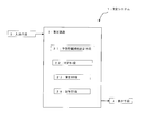
- FIG. 1 is a functional block diagram showing the configuration of the power generation facility operation plan formulation system according to the first embodiment of the present invention.
- FIG. 2 is a schematic diagram for explaining the formulating means according to the first embodiment of the present invention.
- a graph in which the vertical axis represents the power unit price and the horizontal axis represents the time is shown in the predicted power sale price line L_Pe (expected sales price). It is a figure which shows an operation plan side by side while plotting electricity price Pe) and power generation cost Cp.
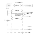
- FIG. 3 is a schematic diagram showing the expected power selling price Pe, the power generation cost Cp, the power generation load Le, the turbine rotation speed ⁇ t, and the calculation formula of the loss index J side by side in the power selling operation mode according to the first embodiment of the present invention.
- FIG. 4 is a diagram showing the expected power selling price Pe, the power generation cost Cp, the power generation load Le, the turbine rotation speed ⁇ t, and the calculation formula of the loss index J side by side in the no-load operation mode according to the first embodiment of the present invention. It is.
- FIG. 5 is a diagram showing the expected power selling price Pe, the power generation cost Cp, the power generation load Le, the turbine rotation speed ⁇ t, and the calculation formula of the loss index J side by side in the stop mode according to the first embodiment of the present invention.
- FIG. 6 is a schematic flowchart for explaining the power plant operating plan formulation method according to the first embodiment of the present invention.
- 7A and 7B are maps for determining weighting factors according to the second embodiment of the present invention.
- FIG. 8 is a schematic diagram for explaining the additional function of the formulating means according to the third embodiment of the present invention.
- the expected power selling price Pe1 It is a figure which plots Pe2, Pe3, and power generation cost Cp, and shows an operation plan side by side.
- FIG. 1 is a functional block diagram showing the configuration of the power generation facility operation plan formulation system according to the first embodiment of the present invention.
- FIG. 2 is a diagram in which an expected power selling price line L_Pe (estimated power selling price Pe) and a power generation cost Cp are plotted on a graph in which the vertical axis represents power unit price and the horizontal axis represents time, and the operation plan is shown side by side.
- L_Pe expected power selling price line
- Cp power generation cost
- FIG. 3 is a diagram showing the expected power selling price Pe, the power generation cost Cp, the power generation load Le, the turbine rotation speed ⁇ t, and the calculation formula of the loss index J side by side in the power selling operation mode.
- FIG. 4 is a diagram showing the expected power selling price Pe, the power generation cost Cp, the power generation load Le, the turbine rotation speed ⁇ t, and the calculation formula for the loss index J side by side in the no-load operation mode.
- FIG. 5 is a diagram showing the expected power selling price Pe, the power generation cost Cp, the power generation load Le, the turbine rotation speed ⁇ t, and the calculation formula of the loss index J in the stop mode.
- a power generation facility operation plan formulation system (hereinafter also simply referred to as a formulation system) 1 according to the present embodiment includes a formulation device 2 and input means (input device) for inputting various types of information to the formulation device 2. ) 3 and display means (display device) 4 for outputting various information from the formulation device 2.
- the input unit 3 and the display unit 4 may be connected to the formulation device 2 via a communication line such as the Internet.
- the formulation device 2 includes an expected power selling price setting unit (expected power selling price setting unit) 21, a determination unit (determination unit) 22, a formulation unit (formulation unit) 23, and a storage unit (storage unit) 29. Configured.
- the storage unit 29 stores various programs and data necessary for the control of the expected power selling price setting unit 21, the determination unit 22, and the formulation unit 23.
- the formulation device 2 is configured by a single device (that is, the expected power selling price setting unit 21, the determination unit 22, the formulation unit 23, and the storage unit 29 are configured by the control function of the same device. However, it is not limited to this.
- the expected power selling price setting unit 21, the determination unit 22, the formulation unit 23, and the storage unit 29 are configured across a plurality of devices, and the plurality of devices are connected via a communication line such as the Internet. May be.
- the expected power selling price setting unit 21, the determination unit 22, and the formulation unit 23 will be described.
- the expected power selling price setting means 21 predicts the predicted power selling price line L_Pe on the prediction target date (here, the next day of bidding) based on the past performance.
- the expected power sale price Pe per unit electric energy fluctuates with time, and the expected power sale price line L_Pe represents the transition of the expected power sale price Pe over 24 hours.
- the predicted power selling price line L_Pe is a step graph created by connecting the predicted power selling price Pe estimated in increments of one hour (see FIG. 2).
- the predicted power selling price Pe is obtained by appropriately correcting the average value in the past performance according to the predicted temperature and predicted weather on the prediction target date.
- predicted power selling price setting means 21 is not essential, and the predicted power selling price information may be acquired from the outside, and the acquired information may be stored in the storage means 29.
- the determining means 22 compares the predicted power selling price Pe with the power generation cost Cp per unit amount of electricity for each time, and determines whether or not the predicted power selling price Pe is higher than the power generation cost Cp.
- the power generation cost Cp is determined according to various specifications of the power generation equipment (type of power generation equipment, type of fuel used, type of turbine drive source, etc.). Here, the power generation cost Cp is appropriately input from the input unit 3 and stored in the storage unit 10. When the power generation cost Cp is expected to be constant over a long period of time, the power generation cost Cp may be stored in the storage unit 10 as a constant in advance.
- the formulating unit 23 formulates an operation plan for 24 hours (predetermined period) by performing selection control for selecting an operation mode (hereinafter also simply referred to as a mode) of the power generation equipment every unit time (here, every hour). To do.
- the power generation facility generates power by driving a power generator with a turbine.
- the power generation facility is a gas turbine combined cycle power plant (GTCC) including a gas turbine, an exhaust gas boiler, a steam turbine, and a power generator.
- GTCC gas turbine combined cycle power plant
- the gas turbine and the steam turbine are collectively referred to as a turbine.
- the power generation operation mode is an operation mode in which the turbine is operated in a state where the turbine is connected to the generator (that is, power generation is performed). In the power generation operation mode, power generation is possible, so power can be sold. Therefore, hereinafter, the power generation operation mode is referred to as a power selling operation mode.
- the no-load operation mode is an operation mode in which the turbine is operated with being disconnected from the generator (that is, the turbine is operated without being loaded). In the no-load operation mode, the generator is not driven (since it does not generate electricity), it cannot sell power.
- the stop mode is an operation mode in which fuel supply to the gas turbine is stopped to stop the turbine and thus the generator. In the stop mode, the generator is stopped (since it does not generate electricity), so power cannot be sold.
- the formulating means 23 operates in the power selling operation mode as the operation mode for the time zone in which the expected power selling price Pe is higher than the power generation cost Cp (that is, the profit period te_p in which profit can be expected if generated). Select a mode.
- the power selling operation mode is selected as the profit period te_p for each time zone from 7:00 to 17:00 and from 18:00 to 20:00.
- the formulating unit 23 uses the following formula for three cases: when the power selling operation mode is performed, when the no-load operation mode is performed, and when the stop mode is performed (when the power generation facility is stopped).
- the power loss J1, the maintenance loss J2, and the operating loss that does not contribute to power sales (hereinafter simply referred to as the operating loss) J3 are used to calculate the loss index J.
- the formulation unit 23 selects an operation mode with the smallest loss index J.
- Loss index J Electricity sales loss J1 + Maintenance loss J2 + Operation loss J3 (1)
- the power selling loss J1 is a loss (so-called reverse shear loss) that occurs because the expected power selling price Pe is lower than the power generation cost Cp when power is sold.
- the maintenance loss J2 is a loss due to an increase in cost or the like resulting from the consumption of a part (part), that is, the life of the part (part) is consumed, resulting in an increase in cost.
- An operation loss is a fuel cost consumed when it does not contribute to power sales (power generation), such as during startup or no-load operation.
- the formulating unit 23 assumes that each of the loss periods te_r is a loss period te_r. Based on the loss index J, the operation mode is selected. As a result, the stop mode is selected from 0:00 to 7:00, the power selling operation mode is selected from 17:00 to 18:00, and the stop mode is selected from 20:00 to 24:00. For the other period, that is, the profit period te_p, the power selling operation mode is selected as the operation mode as described above.
- the operation plan shown in FIG. 2 is formulated, usually, bidding is performed for 7:00 to 20:00 when power generation is performed, and bidding is not performed for other times.
- the power selling operation mode will be described with reference to FIG.
- the power selling operation mode is selected in the loss period te_r where the expected power selling price Pe is lower than the power generation cost Cp
- the generator is continuously driven by the operation of the gas turbine (GT) and the turbine rotational speed ⁇ t and the power generation load Le is a certain value or more.
- operation loss J3 which is a cost associated with start-up and no-load operation, does not occur. Therefore, the loss index J in the power selling operation mode is the sum of the power selling loss J1 and the maintenance loss J2.
- CI is an inspection around the combustion equipment called Combustor Inspection, where parts (CI parts) around the combustion equipment are repaired or replaced.
- TI is an inspection around the turbine called turbine inspection (turbine Inspection), where parts around the turbine (TI parts) are repaired or replaced.
- MI is an inspection of the entire power generation facility called Major Inspection, where parts (MI parts) of the entire power generation facility are repaired or replaced.
- Inspection intervals (hereinafter also simply referred to as intervals) INT_CI, INT_TI, and INT_MI are intervals from the inspection to the next inspection, and are based on the accumulated operation time. In other words, the inspection interval is a use restriction due to the accumulated operation time, and repair or replacement by inspection must be performed when the accumulated operation time is reached. Intervals are shorter in the order of CI, TI, and MI (INT_CI ⁇ INT_TI ⁇ INT_MI), and costs (part repair and replacement costs) are cheaper in the order of CI, TI, and MI (C_CI ⁇ C_TI ⁇ C_MI).
- the above equation (3) occurs in the hatched area defined by the time ⁇ t from time t1 to time t2 (that is, the length of the loss period te_r) and ⁇ C, which is the difference between the power generation cost Cp and the expected power selling price Pe. This is to calculate the power selling loss.
- the above equation (4) is the ratio of the time ⁇ t from time t1 to time t2 (that is, the length of the loss period te_r) to each inspection interval INT_CI, INT_TI, INT_MI, and the cost C_CI required for each inspection CI, TI, MI , C_TI and C_MI are used to calculate a potential maintenance loss at this time ⁇ t.
- the no-load operation mode will be described with reference to FIG.
- the loss index J in the no-load operation mode is the sum of the maintenance loss J2 and the operation loss J3.
- the loss index J in the no-load operation mode is calculated from the inspection intervals INT_CI, INT_TI, INT_MI, the inspection costs C_CI, C_TI, C_MI and the loss period te_r by the following equations (5) to (7).
- the calculation is performed using the time ⁇ t (that is, the length of the no-load operation time), the fuel consumption F_wait per short time during the no-load operation, and the fuel unit price Fee_fuel.
- J J2 + J3 (5)
- J3 F_wait ⁇ ⁇ t ⁇ Fee_fuel (7)
- the fuel consumption amount F_wait is proportional to the turbine rotational speed ⁇ t, and the operation loss J3 calculated from the above equation (7) correlates with the size of the shaded area in FIG. Since the above equation (6) is the same as the above equation (4), description thereof is omitted.
- the stop mode will be described with reference to FIG.
- the loss index J in the stop mode is the sum of the maintenance loss J2 and the operation loss J3.
- stopping the power generation equipment is based on the premise that the gas turbine is subsequently started, and the maintenance loss J2 and the operation loss J3 in the stop mode are both losses focusing on starting.
- the maintenance loss J2 correlates with the speed of consumption of the parts constituting the power generation equipment. Restrictions relating to the consumption of the life of parts include a restriction due to the cumulative operation time and a restriction due to the cumulative number of activations.
- the maintenance loss J2 in the power selling operation mode and the no-load operation mode is related to the limitation of the operation time, whereas the maintenance loss J2 in the stop mode is related to the limitation of the number of activations.
- start-up fuel amount the amount of fuel that is required from the start until the power generation load Le is stabilized
- the loss index J in the stop mode is expressed by the following formulas (8) to (10), the limited number of activations until CI is performed Strt_CI, the limited number of activations until the cost C_CI, TI related to CI is performed The calculation is performed using Strt_MI, the cost C_MI related to MI, the startup fuel amount F_strt, and the fuel unit price Fee_fuel.
- J J2 + J3 (8)
- J3 F_strt ⁇ Fee_Fuel (10)
- FIG. 6 is a schematic flowchart for explaining a method for formulating an operation plan for a power generation facility according to this embodiment.
- step S1 by comparing the predicted power selling price Pe and the power generation cost Cp, the process proceeds to step S6 for a profit period in which the predicted power selling price Pe is higher than the power generation cost Cp within 24 hours.
- the operation mode is selected.
- step S2 for the loss period te_r where the expected power selling price Pe is less than or equal to the power generation cost Cp, the process proceeds to step S2.
- step S2 a loss index J is calculated when each of the power selling operation mode, the no-load operation mode, and the stop mode is selected as the operation mode, and the operation mode in which the loss index J is the minimum is the loss period te_r. Is selected as the operation mode.
- step S3 where the power selling operation mode is selected, and the loss index J is the minimum. If the operation mode is the stop mode, the process proceeds to step S4 and the stop mode is selected. If the operation mode in which the loss index J is the minimum is the no-load operation mode, the process proceeds to step S5 and the no-load operation mode. Is selected. That is, the formulation process of this embodiment is configured by steps S2 to S6.
- the power selling operation mode is selected for a profit period in which the predicted power selling price Pe is higher than the power generation cost Cp, and the predicted power selling price Pe is less than or equal to the power generation cost Cp.
- the operation mode with the smallest loss index is selected from the power selling operation mode, the no-load operation mode, and the stop mode.
- the loss index considers maintenance loss and operational loss that does not contribute to power sales in addition to power sales loss.
- the operation mode in the loss period te_r is selected in consideration of the loss due to the operation at the time of restart or no-load operation that does not contribute. Therefore, a highly profitable operation plan can be formulated.
- FIGS. 7A and 7B are maps for determining weighting factors according to the second embodiment of the present invention.
- the power generation facility operation plan formulation system (formulation method) according to the second embodiment of the present invention functions as a formulation means (formulation method) with respect to the power generation facility operation plan formulation system (formulation method) according to the first embodiment.
- a limitation related to the exhaustion of the life of the component that is, a limitation due to the cumulative operation time and a limitation due to the cumulative number of activations. If one of these limits reaches the limit value, it must be inspected and repaired or replaced.
- the cumulative operation time life (hereinafter also referred to as the operation time life)
- the cumulative number of activations has a margin with respect to the limit number of times (hereinafter also referred to as the operation time life) Repair or replacement must be performed.
- the cumulative number of activations reaches the limit number
- parts must be repaired or replaced even when the cumulative operation time has a margin for the limit time. Therefore, the ideal operation is that the cumulative operation time and the cumulative number of activations reach the respective limit values at the same time.
- control is performed such that the parts can be used up (consumed out) so that the cumulative operation time and the cumulative number of activations are both close to the limit value.
- the fact that the cumulative operation time or the cumulative number of activations approaches the limit value is expressed as consuming the life.
- the lifetime consumption is related to the maintenance loss J2 among the elements of the loss index J.
- the maintenance loss J2 is mainly a loss due to lifetime consumption (operating time loss) related to the accumulated operating time.
- the maintenance loss J2 in the stop mode is accompanied by a restart, and therefore the loss due to the lifetime consumption related to the cumulative number of startups (startup frequency loss) is mainly used. Therefore, in this embodiment, the maintenance loss J2 is calculated by the following equation (11) for the power selling operation mode and the no-load operation mode. That is, the weighting coefficient (first weighting coefficient) k1 is multiplied to the calculation formula of J2 of the first embodiment.
- the maintenance loss J2 is calculated by the following equation (12). That is, the weighting coefficient (second weighting coefficient) k2 is multiplied by the maintenance loss J2 calculation formula of the first embodiment.
- the weighting coefficients k1, k2 are the ratio of the cumulative operating time to the operating time life (cumulative starting time / operating time life, hereinafter referred to as the operating time life consumption rate) C1, and the ratio of the cumulative starting frequency to the starting time life ( Cumulative number of activations / number of activation times (hereinafter referred to as activation number life consumption rate) C2 is determined by the map shown in FIGS. 7A and 7B stored in the storage means 29 in advance. That is, as shown in FIG. 7A, the weighting coefficient k1 is set smaller as the number of activation times life consumption rate C2 is larger and the operation time life consumption rate C1 is smaller, and as shown in FIG. 7B, the operation time life consumption rate C1 is set. The weighting coefficient k2 is set to be smaller as the activation number life consumption rate C2 is smaller.
- the weighting coefficients k1 and k2 may be calculated by a function of the lifetime consumption rates C1 and C2. Furthermore, the weighting coefficients k1 and k2 may be determined by a map or a function in accordance with the ratio between the operating time life consumption rate C1 and the startup frequency life consumption rate C2.
- the power selling operation mode or the no-load operation mode that consumes the operating time life is more easily selected as the operation mode. Since the stop mode that consumes the service life is easily selected as the operation mode, it is possible to prevent the consumption from being biased to one of the start-up service life and the start-up service life, and to reduce the repair and replacement costs associated with parts consumption. be able to.
- the weighting coefficient k1 is decreased and the weighting coefficient k2 is increased as the activation number life consumption rate C2 is increased.
- the weighting coefficient k1 may be decreased as the activation number life consumption rate C2 is increased.
- the weighting factor k2 may be increased.
- the weighting coefficient k2 is decreased and the weighting coefficient k1 is increased as the operating time life consumption C1 is increased.
- the weighting coefficient k2 is increased as the operating time life consumption C1 is increased. It may be as small as possible, or may be increased by the weighting coefficient k1.
- FIG. 8 is a schematic diagram for explaining an additional function of the formulation system (formulation method) according to the third embodiment of the present invention. It is a figure which plots an example of electricity price Pe1, Pe2, Pe3 and power generation cost Cp, and shows an operation plan (operation mode selected for every time) in piles.
- the power generation facility operation plan formulation system (formulation method) according to the third embodiment of the present invention has a function added to the expected power selling price setting unit and a function added to the formulation unit with respect to the first embodiment. ing. Hereinafter, this point will be described.
- the predicted power selling price setting means predicts three predicted power selling price lines L_Pe1, L_Pe2, and L_Pe3 on the prediction target date (here, the day after bidding) based on the past performance. These expected power selling price lines L_Pe1, L_Pe2, L_Pe3 represent the transition of the predicted power selling prices Pe1, Pe2, Pe3 over 24 hours.
- the expected power selling price Pe2 is a price obtained by correcting the average value in the past performance with the weather, temperature, or the like.
- the expected power selling prices Pe1, Pe3 are the prices that allow for the variation of the average value in the past performance, and the expected power selling price Pe1 is the highest expected power selling price obtained by adding the maximum variation on the high price side to the average value.
- the expected power selling price Pe3 is a minimum expected power selling price obtained by subtracting the maximum variation on the low price side from the average value. Therefore, the predicted power sale price Pe1 is also referred to as the highest expected power sale price Pe1, the expected power sale price Pe2 is also referred to as the average power sale price Pe2, and the expected power sale price Pe3 is also referred to as the lowest expected power sale price Pe3. As in the first embodiment, the predicted power sale price setting means is not essential, and the expected power sale price information may be acquired from the outside and the acquired information may be stored in the storage means.
- the formulating means formulates three types of operation plans using the estimated power selling prices Pe1, Pe2, and Pe3. That is, based on the comparison result between the price cost Cp by the judging means and the maximum expected power selling price line L_Pe1 (the highest expected power selling price Pe1), the formulating means formulates a temporary operation plan 100A, and the price cost Cp by the judging means Based on the comparison result with the average expected power selling price line L_Pe2 (average expected power selling price Pe2), the formulating means formulates a temporary operation plan 100B, and the price cost Cp by the judging means 23 and the minimum expected power selling price line L_Pe3 ( Based on the comparison result with the lowest expected power selling price Pe3), the formulating means formulates a temporary operation plan 100C.
- Each temporary operation plan 100A, 100B, 100C is a method of creating a one-day operation plan based on a comparison between the price cost Cp and the expected power sale price line L_Pe (estimated power sale price Pe) in the first embodiment. Developed using the same method.
- the formulating means synthesizes these temporary operation plans 100A, 100B, and 100C to determine a final operation plan (hereinafter also referred to as a main operation plan) 100D.
- a final operation plan hereinafter also referred to as a main operation plan
- the most frequent operation mode among the operation modes constituting each temporary operation plan 100A, 100B, 100C is adopted as the operation mode for that time every hour, and the operation of the temporary operation plans 100A, 100B, 100C is adopted.
- the operation mode of the temporary operation plan 100B based on the average expected power selling price Pe2 is adopted as the operation mode for that time.
- the stop mode is also selected in the actual operation plan 100D.
- the temporary operation plan 100A is in the power selling operation mode, and the temporary operation plans 100B and 100C are in the stop mode. Therefore, the most frequently used stop mode is selected in the main operation plan 100D.
- the temporary operation plans 100A and 100B are in the power selling operation mode, and the temporary operation plan 100C is in the stop mode. Therefore, the most frequently used power selling operation mode is selected in the main operation plan 100D.
- the operation mode most frequently used in the temporary operation plans 100A, 100B, and 100C is selected in the main operation plan 100D.
- the temporary operation plan 100A selects the power selling operation mode
- the temporary operation plan 100B selects the no-load operation mode
- the temporary operation plan 100C selects the stop mode, which is used in the temporary operation plans 100A, 100B, and 100C. Since the operation modes to be performed are different, the no-load operation mode adopted in the temporary operation plan 100B is selected in the main operation plan 100D.
- a provisional operation plan is formulated based on the maximum expected power selling price Pe1, the average expected power selling price Pe2, and the minimum expected power selling price Pe3. Since the operation plan is synthesized into a final operation plan, an operation plan that can cope with the case where the actual power selling price greatly deviates from the average expected value can be adopted.
- the power generation facility is a gas turbine combined cycle power plant (GTCC).
- GTCC gas turbine combined cycle power plant
- the power generation facility operation plan formulation system (formulation method) of the present invention is not limited to application to GTCC.
- it can be applied to a conventional thermal power generation facility including a steam boiler and a steam turbine.
- the loss index J is calculated for each time period when the no-load operation mode is selected and when the stop mode is selected for the time period when the successful bid is not successful. You may make it employ
- the operation mode with the smallest loss index One of the operation modes with the second smallest loss index may be selected by the user.
- the reference value ⁇ J0 may be set based on the predicted accuracy of the predicted power selling price Pe, for example.
Landscapes
- Business, Economics & Management (AREA)
- Engineering & Computer Science (AREA)
- Strategic Management (AREA)
- Economics (AREA)
- Human Resources & Organizations (AREA)
- Development Economics (AREA)
- Entrepreneurship & Innovation (AREA)
- Physics & Mathematics (AREA)
- General Physics & Mathematics (AREA)
- General Business, Economics & Management (AREA)
- Marketing (AREA)
- Theoretical Computer Science (AREA)
- Accounting & Taxation (AREA)
- Finance (AREA)
- Tourism & Hospitality (AREA)
- Game Theory and Decision Science (AREA)
- Health & Medical Sciences (AREA)
- Power Engineering (AREA)
- Operations Research (AREA)
- Quality & Reliability (AREA)
- Data Mining & Analysis (AREA)
- Public Health (AREA)
- Water Supply & Treatment (AREA)
- General Health & Medical Sciences (AREA)
- Primary Health Care (AREA)
- Educational Administration (AREA)
- Automation & Control Theory (AREA)
- General Engineering & Computer Science (AREA)
- Management, Administration, Business Operations System, And Electronic Commerce (AREA)
- Supply And Distribution Of Alternating Current (AREA)
Abstract
Description
このため、発電事業者が電力卸売市場に入札して利益を得るためには、売電価格ひいては電力の需要の変動に応じて如何に最適な運転を行えるかが重要である。
予備力最適化手段は、需要家の負荷増加要求に短時間で応答できる最適な発電量の予備力を算出し、この予備力を維持するためにコスト的に最適な負荷条件を算出する。この最適な負荷条件の一つは定格オーバー負荷であり、特許文献3には、定格オーバー負荷での運転では、設備に余計なストレスを与えることによる機器寿命低減あるいはメンテナンスコストの増大などの運用コストが増加すると記載されている。
ここで、寿命消費コストは、寿命コスト(ある部品を新品時から消耗し交換するまでに必要なコスト)に対してどれだけの余寿命を消費したかによって決まることから、余寿命消費率(余寿命を消費した割合)と寿命コストとの積として算出される(寿命消費コスト=余寿命消費率×寿命コスト)。
損失指標=売電損失+メンテナンス損失+売電に寄与しない運用損失…(1)
損失指標=売電損失+メンテナンス損失+売電に寄与しない運用損失・・・(1)
以下に示す各実施形態では、発電設備の運転計画策定システムを、一日前市場の入札に際して発電設備の24時間(所定期間)に亘る運転計画を策定するのに適用した例を説明する。
[1-1.構成]
本発明の第1実施形態に係る発電設備の運転計画策定システムの全体構成を、図1~5を参照して説明する。
図1は、本発明の第1実施形態の発電設備の運転計画策定システムの構成を示す機能ブロック図である。
図2は、縦軸を電力単価とし横軸を時間とするグラフに、予想売電価格ラインL_Pe(予想売電価格Pe)及び発電コストCpをプロットするとともに、運転計画を並べて示す図である。
図3は、売電運転モードにおいて、予想売電価格Pe,発電コストCp,発電負荷Le及びタービン回転速度ωtと、損失指標Jの計算式とを並べて示す図である。
図4は、無負荷運転モードにおいて、予想売電価格Pe,発電コストCp,発電負荷Le及びタービン回転速度ωtと、損失指標Jの計算式とを並べて示す図である。
図5は、停止モードにおいて、予想売電価格Pe,発電コストCp,発電負荷Le及びタービン回転速度ωtと、損失指標Jの計算式とを並べて示す図である。
なお、入力手段3や表示手段4は、策定装置2とインターネットなどの通信回線を介して接続するようにしても良い。
以下、予想売電価格設定手段21,判定手段22及び策定手段23について説明する。
発電運転モードとは、タービンを発電機とを接続した状態で運転する(すなわち発電を行う)運用モードである。発電運転モードでは発電を行うので売電が可能である。したがって、以下、発電運転モードを売電運転モードという。
無負荷運転モードとは、タービンを発電機から断切した状態で運転する(すなわち負荷が掛らない状態でタービンを運転させる)運用モードである。無負荷運転モードでは発電機は駆動されないので(発電しないので)売電はできない。
停止モードは、ガスタービンへの燃料供給を停止してタービンひいては発電機を停止する運用モードである。停止モードでは、発電機は停止しているので(発電しないので)売電はできない。
策定手段23は、判定手段22の比較結果に基づいて、予想売電価格Peが発電コストCpよりも高い時間帯(すなわち発電すれば収益が見込める収益期間te_p)については、運用モードとして売電運転モードを選択する。図2に示す例では、7時~17時及び18時~20時の各時間帯については、収益期間te_pであるとして売電運転モードが選択される。
損失指標J=売電損失J1+メンテナンス損失J2+運用損失J3 …(1)
なお、図2に示す運転計画が策定された場合には、通常、発電を行う7時~20時について入札を行い、それ以外の時間については入札しない。
先ず、売電運転モードについて図3を参照して説明する。予想売電価格Peが発電コストCpよりも安くなる損失期間te_rにおいて売電運転モードが選択される場合は、ガスタービン(GT)の運転による発電機の駆動が継続されタービン回転速度ωt及び発電負荷Leは一定値以上の値となる。このため、起動時や無負荷運転に伴うコストである運用損失J3が発生することはない。したがって、売電運転モードにおける損失指標Jは、売電損失J1とメンテナンス損失J2との和となる。
J=J1+J2 ・・・(2)


上式(3)は、時刻t1~時刻t2までの時間Δt(すなわち損失期間te_rの長さ)と、発電コストCpと予想売電価格Peとの差額であるΔCにより規定される斜線領域において発生する売電損失を算出するものである。
上式(4)は、時刻t1~時刻t2までの時間Δt(すなわち損失期間te_rの長さ)の各点検インターバルINT_CI,INT_TI,INT_MIに占める比と、各点検CI,TI,MIに要する費用C_CI,C_TI,C_MIとを乗じることで、この時間Δtにおける潜在的なメンテナンス損失を算出するものである。
したがって、無負荷運転モードにおける損失指標Jは、メンテナンス損失J2と運用損失J3との和となる。
J=J2+J3 ・・・(5)

J3=F_wait×Δt×Fee_fuel ・・・(7)
燃料消費量F_waitはタービン回転速度ωtと比例関係にあり、上式(7)より算出される運用損失J3は図4の斜線の領域の大きさと相関する。
なお、上式(6)は上式(4)と同一の式であるので説明を省略する。
したがって、停止モードにおける損失指標Jは、メンテナンス損失J2と運用損失J3との和となる。
ここで、発電設備を停止することは、その後のガスタービンの起動が前提となり、停止モードにおけるメンテナンス損失J2と運用損失J3とは何れも起動に着目した損失である。
先ず、メンテナンス損失J2について説明する。メンテナンス損失J2は発電設備を構成する部品の寿命の消費の速さに相関するものである。部品の寿命の消費に関する制限には、累積運転時間による制限と、累積起動回数による制限とがある。売電運転モードと無負荷運転モードとにおけるメンテナンス損失J2は、運転時間の制限に関連するものであったのに対し、停止モードにおけるメンテナンス損失J2は、起動回数の制限に関連するものである。
J=J2+J3 ・・・(8)

J3=F_strt×Fee_Fuel ・・・(10)
本実施形態の発電設備の運転計画の策定方法(以下、単に策定方法ともいう)について、図6を参照して説明する。
図6は、本実施形態の発電設備の運転計画の策定方法を説明するための模式的なフローチャートである。
第1実施形態の策定システム(策定方法)によれば、予想売電価格Peが発電コストCpよりも高い収益期間については売電運転モードが選択され、予想売電価格Peが発電コストCp以下の損失期間te_rについては、売電運転モード,無負荷運転モード及び停止モードの中から最も損失指標の少ない運用モードが選択される。
損失指標は、売電損失に加えて、メンテナンス損失及び売電に寄与しない運用損失を考慮したものであるから、メンテナンス損失により寿命消耗による潜在的な損失が考慮され、運用損失により、売電には寄与しない再起動時や無負荷運転時の運用による損失が考慮されて、損失期間te_rにおける運用モードが選択される。したがって、利益性の高い運転計画を策定できる。
[2-1.構成]
本発明の第2実施形態に係る発電設備の運転計画策定システム(策定方法)を、図7A及び図7Bを参照して説明する。
図7A及び図7Bは本発明の第2実施形態に係る重み係数を決定するためのマップである。
第1実施形態で前述したように、部品の寿命の消耗に関する制限には、累積運転時間による制限と累積起動回数による制限とがある。この制限の内、どちらか一方が制限値に達した場合には、点検を行って補修又は交換を行わなければならない。
このため、累積運転時間が制限時間(以下、運転時間寿命ともいう)に達した場合には、累積起動回数が制限回数(以下、運転回数寿命ともいう)に対して余裕がある場合でも部品の補修又は交換を行わなければならない。同様に、累積起動回数が制限回数に達した場合には、累積運転時間が制限時間に対して余裕がある場合でも部品の補修又は交換を行わなければならない。
したがって、累積運転時間と累積起動回数とが同時に各制限値に達するのが理想的な運用である。このため、本実施形態では、累積運転時間と累積起動回数とが共に制限値近くまでなるように部品を使いきる(消耗しきる)ことができるような制御を行っている。
以下、累積運転時間や累積起動回数が制限値に近づくことを、寿命を消費すると表現する。
そこで、本実施形態では、売電運転モード及び無負荷運転モードについては下式(11)によりメンテナンス損失J2を、算出する。すなわち、第1実施形態のJ2の計算式に対して重み付け係数(第1重み付け係数)k1を乗じている。

また、停止モードについては下式(12)によりメンテナンス損失J2を算出する。すなわち、第1実施形態のメンテナンス損失J2の計算式に対して重み付け係数(第2重み付け係数)k2を乗じている。

つまり、図7Aに示すように、起動回数寿命消費率C2が大きいほど、運転時間寿命消費率C1が小さいほど、重み付け係数k1が小さく設定され、図7Bに示すように、運転時間寿命消費率C1が大きいほど、起動回数寿命消費率C2が小さいほど、重み付け係数k2が小さく設定される。
さらには、運転時間寿命消費率C1と起動回数寿命消費率C2との比に応じて、マップ又は関数により重み付け係数k1,k2を決定するようにしても良い。
第2実施形態の策定システム(策定方法)によれば、第1実施形態の効果に加え、以下の効果がある。
起動回数寿命消費率C2が大きいほど、また、運転時間寿命消費率C1が小さいほど、重み付け係数k1が小さく設定されることにより、重み付け係数k1を使用して算出される売電運転モード及び無負荷運転モードのメンテナンス損失J2ひいては損失指標Jが少なめに計算される。この結果、重み付け係数を使用しない場合に較べると、相対的に、運転時間寿命を消費する売電運転モード又は無負荷運転モードが選択されやすくなる。
逆に、運転時間寿命消費率C1が大きいほど、また、起動回数寿命消費率C2が小さいほど、重み付け係数k2が小さく設定されることにより、重み付け係数k2を使用して算出される停止モードのメンテナンス損失J2ひいては損失指標Jが少なめに計算される。この結果、重み付け係数を使用しない場合に較べると、相対的に、起動時間寿命を消費する停止モードが選択されやすくなる。
上記実施形態では、起動回数寿命消費率C2が大きいほど、重み付け係数k1を小さくするとともに重み付け係数k2を大きくしているが、起動回数寿命消費率C2が大きいほど、重み付け係数k1だけ小さくしてもよいし、重み付け係数k2だけ大きくしても良い。
同様に、上記実施形態では、運転時間数寿命消費率C1が大きいほど、重み付け係数k2を小さくするとともに重み付け係数k1を大きくしているが、運転時間数寿命消費率C1が大きいほど、重み付け係数k2だけ小さくしてもよいし、重み付け係数k1だけ大きくしても良い。
[3-1.構成]
本発明の第3実施形態に係る発電設備の運転計画策定システム(策定方法)を、図8を参照して説明する。
図8は、本発明の第3実施形態に係る策定システム(策定方法)の追加機能を説明するための模式図であって、縦軸を電力単価とし横軸を時間とするグラフに、予想売電価格Pe1,Pe2,Pe3及び発電コストCpの一例をプロットするとともに、運転計画(各時間毎に選択された運転モード)を重ねて示す図である。
予想売電価格Pe2は、過去の実績における平均値を天気や気温などで修正した価格である。予想売電価格Pe1,Pe3は、過去の実績における平均値に対するばらつきを見込んだ価格であり、予想売電価格Pe1は、平均値に高値側の最大ばらつきを加算して求めた、最高予想売電価格であり、予想売電価格Pe3は、平均値に安値側の最大ばらつきを減算した最低予想売電価格である。そこで、予想売電価格Pe1を最高予想売電価格Pe1、予想売電価格Pe2を平均売電価格Pe2、予想売電価格Pe3を最低予想売電価格Pe3ともいう。
なお、第1実施形態と同様に、予想売電価格設定手段は必須ではなく、外部から予想売電価格情報を取得して、この取得した情報を記憶手段に記憶させるようにしても良い。
各仮運転計画100A, 100B, 100Cは、第1実施形態で、価格コストCpと予想売電価格ラインL_Pe(予想売電価格Pe)との比較に基づいて1日の運転計画を作成した方法と同じ方法を使用して策定される。
第3実施形態の策定システム(策定方法)によれば、最大予想売電価格Pe1,平均予想売電価格Pe2及び最低予想売電価格Pe3の3つに基づいて仮運転計画を策定し、この仮運転計画を合成して最終的な運転計画としているので、実際の売電価格が平均的な予想値から大きく外れるような場合でも、それに対応できる運転計画を採用することができる。
(1)上記実施形態では、仮運転計画100A,100B,100Cの運用モードがすべて異なる場合は、平均予想売電価格Pe2に基づく仮運転計画100Bの運用モードをその時間の運用モードとして採用するようにしたが、仮運転計画100A, 100B, 100Cの運用モードがすべて異なる場合には、入力手段(選択運用モード取得手段)3からどの運用モードを選択するかユーザにより選択させるようにしても良い。この場合、表示手段(推奨運用モード表示手段)4に、仮運転計画100Bが採用しているモードを推奨する表示させても良い。
これにより、仮運転計画100A, 100B, 100Cのモードがすべて異なる場合は、ユーザの知見に基づいてモードを選択することができる。
(2)仮運転計画100A, 100B, 100Cを策定する際に、第2実施形態のように重み付け係数k1,k2を用いてメンテナンス損失J2を算出するようにしても良い。
(1)上記各実施形態では、発電設備をガスタービンコンバインドサイクル発電プラント(GTCC)としたが、本発明の発電設備の運転計画の策定システム(策定方法)は、GTCCへの適用に限定されない。例えば、蒸気ボイラと蒸気タービンからなる従来火力発電設備にも適用できるものである。
2 策定装置
3 入力手段(選択運用モード取得手段)
4 表示手段(推奨運用モード表示手段)
21 予想売電価格設定手段
22 判定手段
23 策定手段
29 記憶手段
100,100D 運転計画
100A,100B,100C 仮運転計画
C1 起動回数寿命消費率
C2 運転時間寿命消費率
Cp 発電コスト
C_CI CIに係る費用
C_MI MIに係る費用
C_TI TIに係る費用
F_wait 燃料消費量
Fee_fuel 燃料単価
F_strt 起動時燃料量
J 損失指標
J1 売電損失
J2 メンテナンス損失
J3 運用損失
k1 重み付け係数(第1重み付け係数)
k2 重み付け係数(第2重み付け係数)
L_Pe, L_Pe1,L_Pe2,L_Pe3 予想売電価格ライン
Le 発電負荷
Pe1,Pe2,Pe3 予想売電価格
Strt_CI CIの制限起動回数
Strt _MI の制限起動回数
Strt _TI の制限起動回数
te_p 収益期間
te_r 損失期間
ΔC 単位発電量当たりの損失
INT_CI CIを行うまでのインターバル
INT_MI MIを行うまでのインターバル
INT_TI TIを行うまでのインターバル
Le 損失期間te_rにおける発電負荷
Δt 損失期間te_rの時間
ΔJ 最も小さい損失指標と、二番目に小さい損失指標との差
ΔJ0 ΔJの基準値
ωt タービン回転速度
Claims (8)
- タービンにより発電機を駆動して発電し、前記タービンと前記発電機とを接続した状態で運転して売電する売電運転モード, 前記タービンと前記発電機とを断切した状態で運転する無負荷運転モード及び前記タービンを停止する停止モードの何れかの運用モードを実行可能な発電設備において、発電コストと、時間にしたがって変動する予想売電価格との比較に基づき前記運用モードを選択して、所定期間に亘る運転計画を策定する、発電設備の運転計画の策定システムであって、
前記予想売電価格と前記発電コストとの比較を行って、前記予想売電価格が前記発電コストよりも高いか否かを判定する判定手段と、
前記判定手段の判定結果に基づいて、前記所定期間の内、前記予想売電価格が前記発電コストよりも高い収益期間については売電運転モードとし、前記所定期間の内、前記予想売電価格が前記発電コスト以下の損失期間については、前記売電運転モード,前記無負荷運転モード及び前記停止モードのそれぞれについて、下式(1)により損失指標を算出し、前記3つの運用モードの中から、前記損失指標の最も少ない運用モードを選択する選択制御を行うことで、前記売電運転モード,前記無負荷運転モード及び前記停止モードの少なくとも1つからなる前記運転計画を策定する、策定手段とを備えた
ことを特徴とする、発電設備の運転計画策定システム。
損失指標=売電損失+メンテナンス損失+売電に寄与しない運用損失…(1) - 前記メンテナンス損失には、前記発電設備の累積運転時間によって前記発電設備を構成する部品の運転時間についての寿命を消費する運転時間損失と、前記発電設備の累積起動回数によって前記部品の起動回数についての寿命を消費する起動回数損失とがあり、
前記売電運転モード及び前記無負荷運転モードのそれぞれの前記メンテナンス損失は前記運転時間損失が主体であり、
前記停止モードの前記メンテナンス損失は前記起動回数損失が主体であり、
前記策定手段は、
前記売電運転モード及び前記無負荷運転モードのそれぞれの前記メンテナンス損失を、第1重み付け係数を使用して決定し、
前記停止モードの前記メンテナンス損失を、第2重み付け係数を使用して決定し、
前記起動回数についての寿命に対する前記累積起動回数の比率が大きくなるほど、前記第1重み付け係数を小さくするか、前記第2重み付け係数を大きくするか、又は、前記第1重み付け係数を小さくするとともに前記第2重み付け係数を大きくし、
前記運転時間についての寿命に対する前記累積運転時間の比率が大きくなるほど、前記第1重み付け係数を大きくするか、前記第2重み付け係数を小さくするか、又は、前記第1重み付け係数を大きくするとともに前記第2重み付け係数を小さくする
ことを特徴とする、請求項1記載の発電設備の運転計画策定システム。 - 前記予想売電価格として、最低予想売電価格,平均予想売電価格及び最高予想売電価格の三つの価格を使用し、
前記判定手段は、前記最低予想売電価格,前記平均予想売電価格及び前記最高予想売電価格のそれぞれについて、前記発電コストとの比較を行って、前記予想売電価格が前記発電コストよりも高いか否かを判定し、
前記策定手段は、前記最低予想売電価格,前記平均予想売電価格及び前記最高予想売電価格のそれぞれについて、前記選択制御を行うことで、前記所定期間における仮運転計画を策定し、前記最低予想売電価格に基づく第1仮運転計画と、前記平均予想売電価格に基づく第2仮運転計画と、前記最高予想売電価格に基づく第3仮運転計画とを合成して、前記運転計画を策定する
ことを特徴とする、請求項1又は2記載の発電設備の運転計画策定システム。 - 前記策定手段は、前記第1仮運転計画,前記第2仮運転計画及び前記第3仮運転計画のそれぞれにおいて同じ時刻に対して選択されている前記運用モードの中から、最も多く選択されている前記運用モードを採用することで、前記合成を行う
ことを特徴とする、請求項3記載の発電設備の運転計画策定システム。 - 前記策定手段は、前記第1仮運転計画,前記第2仮運転計画及び前記第3仮運転計画のそれぞれにおいて同じ時刻に対して選択されている前記運用モードが何れも異なる場合には、前記第2仮運転計画において選択されている前記運用モードを採用することで、前記合成を行う
ことを特徴とする、請求項4記載の発電設備の運転計画策定システム。 - 選択運用モード取得手段を備え、
前記策定手段は、前記第1仮運転計画,前記第2仮運転計画及び前記第3仮運転計画のそれぞれにおいて同じ時刻に対して選択されている前記運用モードが何れも異なる場合には、前記選択運用モード取得手段により取得した前記運用モードを採用することで、前記合成を行う
ことを特徴とする、請求項4記載の発電設備の運転計画策定システム。 - 推奨運用モード表示手段を備え、
前記策定手段は、前記第1仮運転計画,前記第2仮運転計画及び前記第3仮運転計画のそれぞれにおいて同じ時刻に対して選択されている前記運用モードが何れも異なる場合には、前記推奨運用モード表示手段に、推奨運用モードとして、前記第2仮運転計画の前記運用モードを表示する
ことを特徴とする、請求項6記載の発電設備の運転計画策定システム。 - タービンにより発電機を駆動して発電し、前記タービンと前記発電機とを接続した状態で運転して売電する売電運転モード, 前記タービンと前記発電機とを断切した状態で運転する無負荷運転モード及び前記タービンを停止する停止モードの何れかの運用モードを実行可能な発電設備において、発電コストと、時間にしたがって変動する予想売電価格との比較に基づき前記運用モードを選択して、所定期間に亘る運転計画を策定する、発電設備の運転計画の策定方法であって、
前記予想売電価格と前記発電コストとの比較を行って、前記予想売電価格が前記発電コストよりも高いか否かを判定する判定工程と、
前記判定工程の判定結果に基づいて、前記所定期間の内、前記予想売電価格が前記発電コストよりも高い収益期間については売電運転モードとし、前記所定期間の内、前記予想売電価格が前記発電コスト以下の損失期間については、前記売電運転モード,前記無負荷運転モード及び前記停止モードのそれぞれについて、下式(1)により損失指標を算出し、前記3つの運用モードの中から、前記損失指標の最も少ない運用モードを選択することで、前記売電運転モード,前記無負荷運転モード及び前記停止モードの少なくとも1つからなる前記運転計画を策定する、策定工程とを備えた
ことを特徴とする、発電設備の運転計画策定方法。
損失指標=売電損失+メンテナンス損失+売電に寄与しない運用損失…(1)
Priority Applications (2)
| Application Number | Priority Date | Filing Date | Title |
|---|---|---|---|
| DE112015006251.3T DE112015006251B4 (de) | 2015-03-02 | 2015-09-24 | Betriebsplan-planungssystem zum planen eines betriebsplans eines kraftwerks |
| US15/554,317 US10410301B2 (en) | 2015-03-02 | 2015-09-24 | Operation plan planning system for planning an operation plan of a power plant and operation plan planning method for planning an operation plan of a power plant |
Applications Claiming Priority (2)
| Application Number | Priority Date | Filing Date | Title |
|---|---|---|---|
| JP2015040351A JP6534537B2 (ja) | 2015-03-02 | 2015-03-02 | 発電設備の運転計画策定システム及び発電設備の運転計画策定方法 |
| JP2015-040351 | 2015-03-02 |
Publications (1)
| Publication Number | Publication Date |
|---|---|
| WO2016139836A1 true WO2016139836A1 (ja) | 2016-09-09 |
Family
ID=56847476
Family Applications (1)
| Application Number | Title | Priority Date | Filing Date |
|---|---|---|---|
| PCT/JP2015/076991 Ceased WO2016139836A1 (ja) | 2015-03-02 | 2015-09-24 | 発電設備の運転計画策定システム及び発電設備の運転計画策定方法 |
Country Status (4)
| Country | Link |
|---|---|
| US (1) | US10410301B2 (ja) |
| JP (1) | JP6534537B2 (ja) |
| DE (1) | DE112015006251B4 (ja) |
| WO (1) | WO2016139836A1 (ja) |
Cited By (1)
| Publication number | Priority date | Publication date | Assignee | Title |
|---|---|---|---|---|
| JP2019040483A (ja) * | 2017-08-28 | 2019-03-14 | 三菱電機株式会社 | 電力取引策定装置 |
Families Citing this family (5)
| Publication number | Priority date | Publication date | Assignee | Title |
|---|---|---|---|---|
| US11875371B1 (en) | 2017-04-24 | 2024-01-16 | Skyline Products, Inc. | Price optimization system |
| JP7372727B2 (ja) * | 2017-11-20 | 2023-11-01 | 三菱重工業株式会社 | 系統運用者側コンピュータ、発電事業者側コンピュータ、電力システム、制御方法及びプログラム |
| JP7315315B2 (ja) * | 2018-10-02 | 2023-07-26 | 一般財団法人電力中央研究所 | 運転支援システム、運転支援装置、運転支援方法およびプログラム |
| JP7194390B2 (ja) * | 2020-11-30 | 2022-12-22 | booost technologies株式会社 | 特典付与システム、特典付与方法および特典付与プログラム |
| CN116307502B (zh) * | 2023-01-30 | 2024-09-03 | 国网江苏省电力有限公司南京供电分公司 | 一种积木式储能系统减少停电损失的优化配置方法 |
Citations (3)
| Publication number | Priority date | Publication date | Assignee | Title |
|---|---|---|---|---|
| JPH09179604A (ja) * | 1995-09-13 | 1997-07-11 | Toshiba Corp | プラントの運転制御システム及び方法 |
| JP2001086645A (ja) * | 1999-09-17 | 2001-03-30 | Mitsubishi Electric Corp | 発電設備の最適運転計画算出方法およびその装置 |
| JP2008146105A (ja) * | 2006-12-05 | 2008-06-26 | Toshiba Corp | 電力取引評価システムと方法、およびプログラム |
Family Cites Families (10)
| Publication number | Priority date | Publication date | Assignee | Title |
|---|---|---|---|---|
| US5873251A (en) | 1995-09-13 | 1999-02-23 | Kabushiki Kaisha Toshiba | Plant operation control system |
| US5966925A (en) * | 1996-04-26 | 1999-10-19 | Kabushiki Kaisha Toshiba | Gas turbine power plant control for starting and stopping |
| JP2001318970A (ja) | 2000-05-12 | 2001-11-16 | Nippon Steel Corp | 電力の需給制御方法、電力の需給制御装置、電力の需給制御システム及び記憶媒体 |
| JP3970536B2 (ja) * | 2001-03-19 | 2007-09-05 | 三菱電機株式会社 | 発電設備の最適運転計画策定方法 |
| JP3791503B2 (ja) | 2003-03-12 | 2006-06-28 | 株式会社日立製作所 | 発電計画・電力売買計画作成方法,装置及びプログラム |
| US8069077B2 (en) * | 2003-06-11 | 2011-11-29 | Kabushiki Kaisha Toshiba | Electric-power-generating-facility operation management support system, electric-power-generating-facility operation management support method, and program for executing support method, and program for executing operation management support method on computer |
| JP2006271148A (ja) * | 2005-03-25 | 2006-10-05 | Osaka Gas Co Ltd | 電力調達計画システム |
| JP4413857B2 (ja) * | 2005-12-02 | 2010-02-10 | 中部電力株式会社 | 電力取引評価支援システムと方法、およびプログラム |
| US9477214B2 (en) * | 2013-03-07 | 2016-10-25 | General Electric Company | Plant control systems and methods |
| JP6816949B2 (ja) * | 2014-11-26 | 2021-01-20 | ゼネラル・エレクトリック・カンパニイ | 発電プラント発電ユニットの制御を強化するための方法 |
-
2015
- 2015-03-02 JP JP2015040351A patent/JP6534537B2/ja active Active
- 2015-09-24 US US15/554,317 patent/US10410301B2/en active Active
- 2015-09-24 DE DE112015006251.3T patent/DE112015006251B4/de active Active
- 2015-09-24 WO PCT/JP2015/076991 patent/WO2016139836A1/ja not_active Ceased
Patent Citations (3)
| Publication number | Priority date | Publication date | Assignee | Title |
|---|---|---|---|---|
| JPH09179604A (ja) * | 1995-09-13 | 1997-07-11 | Toshiba Corp | プラントの運転制御システム及び方法 |
| JP2001086645A (ja) * | 1999-09-17 | 2001-03-30 | Mitsubishi Electric Corp | 発電設備の最適運転計画算出方法およびその装置 |
| JP2008146105A (ja) * | 2006-12-05 | 2008-06-26 | Toshiba Corp | 電力取引評価システムと方法、およびプログラム |
Cited By (2)
| Publication number | Priority date | Publication date | Assignee | Title |
|---|---|---|---|---|
| JP2019040483A (ja) * | 2017-08-28 | 2019-03-14 | 三菱電機株式会社 | 電力取引策定装置 |
| JP7024256B2 (ja) | 2017-08-28 | 2022-02-24 | 三菱電機株式会社 | 電力取引策定装置 |
Also Published As
| Publication number | Publication date |
|---|---|
| DE112015006251T5 (de) | 2017-11-30 |
| JP6534537B2 (ja) | 2019-06-26 |
| US20180040079A1 (en) | 2018-02-08 |
| US10410301B2 (en) | 2019-09-10 |
| DE112015006251B4 (de) | 2025-04-24 |
| JP2016163431A (ja) | 2016-09-05 |
Similar Documents
| Publication | Publication Date | Title |
|---|---|---|
| US11699903B2 (en) | Building energy optimization system with economic load demand response (ELDR) optimization and ELDR user interfaces | |
| CN108694271B (zh) | 燃气涡轮机调配优化系统及方法及非暂态计算机可读介质 | |
| US10732584B2 (en) | Building energy optimization system with automated and dynamic economic load demand response (ELDR) optimization | |
| Martin et al. | A stochastic two settlement equilibrium model for electricity markets with wind generation | |
| JP6534537B2 (ja) | 発電設備の運転計画策定システム及び発電設備の運転計画策定方法 | |
| US20050015283A1 (en) | Electric-power-generating-facility operation management support system, electric-power-generating-facility operation management support method, and program for executing support method, and program for executing operation management support method on computer | |
| JP6924104B2 (ja) | 電力価格予測システム | |
| JP2002271982A (ja) | 余剰電力管理システムおよびその制御方法 | |
| JP2008295175A (ja) | 発電機の運転計画策定装置、運転計画策定方法ならびに、その装置および方法を実行させるためのプログラム | |
| Poletti | The economics of electricity markets: theory and policy | |
| Fleten et al. | Structural estimation of switching costs for peaking power plants | |
| Kirby et al. | Providing minute-to-minute regulation from wind plants | |
| JP2001086645A (ja) | 発電設備の最適運転計画算出方法およびその装置 | |
| JP2015087886A (ja) | 売電計画作成方法、売電計画作成装置、売電計画作成システム及び売電計画作成プログラム | |
| Heredia et al. | A stochastic programming model for the optimal electricity market bid problem with bilateral contracts for thermal and combined cycle units | |
| JP2003111275A (ja) | 発電設備運用計画システム及び売電システム | |
| Beiter et al. | The potential impact of offshore wind energy on a future power system in the US northeast | |
| JP4075872B2 (ja) | 供給力の運用計画作成方法および運用計画作成装置 | |
| JP2017519296A (ja) | 代替運転モードを用いた発電システムの経済的最適化 | |
| JP2019205304A (ja) | 電力取引システムおよびその方法 | |
| JP2017173945A (ja) | 契約電力最適化装置 | |
| Aasgård et al. | Comparing bidding methods for hydropower | |
| Anders et al. | Commitment techniques for combined-cycle generating units | |
| JP6682024B1 (ja) | 発電設備の評価装置、発電設備の評価システム、発電設備の評価方法、及びプログラム | |
| JP2022116423A (ja) | 電力取引支援装置 |
Legal Events
| Date | Code | Title | Description |
|---|---|---|---|
| 121 | Ep: the epo has been informed by wipo that ep was designated in this application |
Ref document number: 15884002 Country of ref document: EP Kind code of ref document: A1 |
|
| WWE | Wipo information: entry into national phase |
Ref document number: 15554317 Country of ref document: US |
|
| WWE | Wipo information: entry into national phase |
Ref document number: 112015006251 Country of ref document: DE |
|
| 122 | Ep: pct application non-entry in european phase |
Ref document number: 15884002 Country of ref document: EP Kind code of ref document: A1 |
|
| WWG | Wipo information: grant in national office |
Ref document number: 112015006251 Country of ref document: DE |