WO2016139711A1 - 熱交換装置、燃料ガス生成装置 - Google Patents
熱交換装置、燃料ガス生成装置 Download PDFInfo
- Publication number
- WO2016139711A1 WO2016139711A1 PCT/JP2015/056060 JP2015056060W WO2016139711A1 WO 2016139711 A1 WO2016139711 A1 WO 2016139711A1 JP 2015056060 W JP2015056060 W JP 2015056060W WO 2016139711 A1 WO2016139711 A1 WO 2016139711A1
- Authority
- WO
- WIPO (PCT)
- Prior art keywords
- pipe
- slurry body
- heat exchange
- slurry
- fluid
- Prior art date
- Legal status (The legal status is an assumption and is not a legal conclusion. Google has not performed a legal analysis and makes no representation as to the accuracy of the status listed.)
- Ceased
Links
Images



Classifications
-
- C—CHEMISTRY; METALLURGY
- C10—PETROLEUM, GAS OR COKE INDUSTRIES; TECHNICAL GASES CONTAINING CARBON MONOXIDE; FUELS; LUBRICANTS; PEAT
- C10J—PRODUCTION OF PRODUCER GAS, WATER-GAS, SYNTHESIS GAS FROM SOLID CARBONACEOUS MATERIAL, OR MIXTURES CONTAINING THESE GASES; CARBURETTING AIR OR OTHER GASES
- C10J3/00—Production of combustible gases containing carbon monoxide from solid carbonaceous fuels
- C10J3/72—Other features
-
- F—MECHANICAL ENGINEERING; LIGHTING; HEATING; WEAPONS; BLASTING
- F28—HEAT EXCHANGE IN GENERAL
- F28D—HEAT-EXCHANGE APPARATUS, NOT PROVIDED FOR IN ANOTHER SUBCLASS, IN WHICH THE HEAT-EXCHANGE MEDIA DO NOT COME INTO DIRECT CONTACT
- F28D7/00—Heat-exchange apparatus having stationary tubular conduit assemblies for both heat-exchange media, the media being in contact with different sides of a conduit wall
- F28D7/10—Heat-exchange apparatus having stationary tubular conduit assemblies for both heat-exchange media, the media being in contact with different sides of a conduit wall the conduits being arranged one within the other, e.g. concentrically
-
- F—MECHANICAL ENGINEERING; LIGHTING; HEATING; WEAPONS; BLASTING
- F28—HEAT EXCHANGE IN GENERAL
- F28G—CLEANING OF INTERNAL OR EXTERNAL SURFACES OF HEAT-EXCHANGE OR HEAT-TRANSFER CONDUITS, e.g. WATER TUBES OR BOILERS
- F28G13/00—Appliances or processes not covered by groups F28G1/00 - F28G11/00; Combinations of appliances or processes covered by groups F28G1/00 - F28G11/00
Definitions
- the present invention relates to a heat exchange device and a fuel gas generation device.
- a heat exchange device having a pipe through which a slurry body moves so that heat exchange with an external fluid is performed is known (for example, Patent Document 1).
- the main present invention that solves the above-described problem includes a first pipe through which a slurry body moves so that heat exchange is performed with an external fluid, and the downstream end of the first pipe is
- the heat exchange device is characterized in that the shape of the slurry body adhering to the inner wall of the first pipe is less than a predetermined amount.
- FIG. 1 is a block diagram showing a supercritical gasifier in the present embodiment.
- the supercritical gasifier 100 (fuel gas generator) is a device that generates fuel gas from a gasification raw material or the like.
- the supercritical gasifier 100 includes a raw material adjustment unit 10, a raw material supply unit 20, a heat exchange unit 30, a gasification processing unit 40, and a fuel generation unit 50.
- the raw material adjustment unit 10 is a part that adjusts a raw material slurry (also referred to as “slurry body” or “raw material”) from a gasification raw material or the like, and includes an adjustment tank 11 and a crusher 12.
- a raw material slurry also referred to as “slurry body” or “raw material”
- the raw material adjustment unit 10 includes an adjustment tank 11 and a crusher 12.
- the adjustment tank 11 is a container for preparing a suspension by mixing gasification raw materials, activated carbon, water, and the like, and is provided with a stirring blade (not shown).
- gasification raw material for example, shochu residue, egg-collected chicken manure, and sludge can be used.
- Activated carbon functions as a nonmetallic catalyst, and porous particles having an average particle diameter of 200 ⁇ m or less can be used.
- the crusher 12 is a device for crushing the solid content (mainly gasification raw material) contained in the suspension mixed in the adjustment tank 11 to obtain a uniform size. In this embodiment, crushing is performed so that the average particle size of the solid content is 500 ⁇ m or less. Due to crushing by the crusher 12, the suspension becomes a raw slurry.
- the raw material supply unit 20 is a part that feeds the raw material slurry at a high pressure, and includes a supply pump 21 and a high pressure pump 22.
- the supply pump 21 is a device for supplying the raw slurry sent from the crusher 12 toward the high-pressure pump 22.
- the high-pressure pump 22 is a device for sending the raw slurry at high pressure.
- the raw material slurry is pressurized to about 0.1 to 4 MPa by the high-pressure pump 22.
- the heat exchange unit 30 heats the raw material slurry by causing heat exchange between the raw material slurry supplied from the raw material supply unit 20 and the processed fluid after being decomposed by the gasification processing unit 40. At the same time, it is a part that cools the processed fluid.
- the heat exchange unit 30 includes a heat exchanger 6 (heat exchange device) and a cooler 32.
- the heat exchanger 6 is a device that exchanges heat between the raw slurry and the treated fluid, and a double tube type is used.
- the inner channel is used as a low temperature side channel through which the raw material slurry flows, and the outer channel is used as a high temperature side channel through which the treated fluid flows.
- the introduction temperature of the treated fluid is about 600 ° C.
- the discharge temperature is about 120 ° C.
- the introduction temperature of the raw slurry is normal temperature and the discharge temperature is about 450 ° C.
- the cooler 33 is a device that cools the processed fluid discharged from the heat exchanger 6.
- the gasification processing unit 40 is a part that heats the raw material slurry heated by the heat exchanger 6 to a supercritical state and decomposes organic substances contained in the raw material slurry, and has a preheater 41 and a gasification reactor 42. ing.
- the preheater 41 is a device for preheating the raw material slurry discharged from the heat exchanger 6, and in this embodiment, the raw material slurry introduced at about 450 ° C is heated to about 600 ° C.
- the gasification reactor 42 is an apparatus for decomposing organic substances contained in the raw material slurry while maintaining the raw material slurry in a supercritical state. In this embodiment, the temperature is set to 600 ° C. and the pressure is set to 25 MPa, and the raw material slurry is decomposed for 1 to 2 minutes.
- the fuel generator 50 generates fuel gas from the processed fluid.
- the fuel generator 50 includes a decompressor 51, a gas-liquid separator 51, a catalyst recovery unit, and a gas tank 54.
- the decompressor 51 decompresses the processed fluid cooled by the cooler 32.
- the gas-liquid separator 52 separates the processed fluid decompressed by the decompressor 51 into a gas (fuel gas) and a liquid (drainage, activated carbon, ash). Then, the separated liquid is discharged via the catalyst recovery unit 53. On the other hand, the separated gas is stored in the gas tank 54.
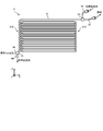
- FIG. 2 is a perspective view showing a heat exchanger in the present embodiment.
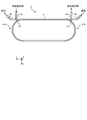
- FIG. 3 is a plan view showing the heat exchanger in the present embodiment.
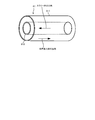
- FIG. 4 is a cross-sectional perspective view showing the double tube in the present embodiment.
- FIG. 4 shows the double pipe 61 in a state viewed from a cross section substantially orthogonal to the longitudinal direction of the double pipe 61. A part of the inner tube 612 is indicated by a broken line for
- the heat exchanger 6 is a device that exchanges heat between the slurry body and the treated fluid.
- the processed fluid is a slurry body processed by the gasification processing unit 40.
- the heat exchanger 6 has a double pipe 61 and pipes 62 to 65.
- the double pipe 61 has an outer pipe 611 and an inner pipe 612.
- the inner pipe 612 is, for example, a metal pipe through which the slurry body moves.
- the inner tube 612 is inserted into the outer tube 611 so that a gap for moving the processed fluid is formed between the inner tube 612 and the outer tube 611.
- the inner side of the inner pipe 612 corresponds to the inner flow path, and the gap between the inner pipe 612 and the outer pipe 611 corresponds to the outer flow path.
- the outer tube 611 is, for example, a metal pipe through which the inner tube 612 is inserted.
- the double pipe 61 is centered on a winding axis (not shown) along the vertical direction (Z axis) so that the length of the double pipe 61 can be relatively long in a relatively narrow space. It is wound in a spiral. That is, the outer tube 611 and the inner tube 612 are both spirally wound.
- the pipes 62 and 63 are coupled to one end of the double pipe 61 via a coupling portion P2 provided on the upper side (+ Z) from the coupling portion P1.
- the pipe 62 is coupled so as to communicate with the inner flow path.
- the pipe 63 is coupled so as to communicate with the outer flow path.
- the inner pipe 612 and the pipe 62 correspond to the first pipe.
- the outer pipe 611 corresponds to the second pipe.
- the pipes 64 and 65 are coupled to the other end of the double pipe 61 through a coupling part P1 provided on the lower side ( ⁇ Z) than the coupling part P2.
- the pipe 65 is coupled so as to communicate with the inner flow path.
- the pipe 64 is coupled so as to communicate with the outer flow path.
- a slurry body is supplied to the pipe 65 from the raw material supply unit 20.
- This slurry body is supplied to the gasification processing unit 40 via the inner flow path of the double pipe 61 and the pipe 62.
- the post-treatment fluid is supplied to the pipe 63 from the gasification processing unit 40.
- the post-treatment fluid is supplied to the cooler 32 via the outer flow path of the double pipe 61 and the pipe 64. That is, in the double pipe 61, the flow direction of the slurry body and the flow direction of the processed fluid are opposed to each other.
- FIG. 5 is a side view showing another pipe.
- FIG. 6 is a side view showing the piping in the present embodiment.
- FIG. 6 shows the pipe 62 in a state where the product T1 in FIG. 5 flows toward the downstream side without adhering to the inner wall.
- Other piping, products
- the other pipe 620 is another heat exchanger pipe having the same configuration as the pipe 62 of the heat exchanger 6.
- the radius of curvature of the bent portion 62B of the other pipe 620 is smaller than the radius of curvature of the pipe 62, and is set to about 38 (mm), for example.
- the configuration of the other heat exchangers other than the other pipes 620 is the same as the configuration of the heat exchanger 6.
- the product T1 may adhere to the bent portion 62B of the other pipe 620 and the inner wall near the bent portion 62B on the downstream side of the bent portion 62B. This is based on, for example, the change in the moving direction and moving speed of the slurry body in the bent portion 62B.
- the slurry body comes into contact with the inner wall of the pipe at a position where the moving direction of the slurry body changes suddenly, but the position is also a position where the moving speed is reduced, so that the product T1 adheres and is easily laminated.
- the product T1 is, for example, tar and char generated when the slurry body is heated.
- the movement of the slurry body may be hindered by the adhering product T1.
- the moving speed of the slurry body is reduced and the slurry body adheres to the inner wall of the other heat exchanger, and the slurry body in the other heat exchanger
- the heat transfer rate with the fluid after treatment may be reduced.
- the other pipe 620 may be blocked. In this case, it may be difficult for another supercritical gasifier having another heat exchanger to generate the fuel gas.
- the amount of the product T1 adhering to the inner wall of the pipe 62 needs to be smaller than a predetermined amount.
- the predetermined amount may be, for example, an amount that does not block the pipe 62, and the heat exchanger 6 has a heat passage rate that allows the temperature of the slurry discharged from the pipe 62 to be about 450 ° C. It is good also as a quantity defined based on experiment or simulation whether it can be maintained in.
- Curvature radius of piping 62 The pipe 62 has a shape bent so that the radius of curvature of the bent portion 62A in the pipe 62 is larger than the radius of curvature of the bent portion 62B in the other pipe 620.
- the radius of curvature of the bending portion 62A is set to a predetermined radius of curvature based on, for example, experiments or simulations so that the amount of the product T1 adhering to the inner wall of the pipe 62 is smaller than the predetermined amount.
- the predetermined radius of curvature may be about 200 (mm), which is the same as the radius of curvature of the bent portions 61A and 61B (FIG. 3) of the double pipe 61.
- the raw material adjusting unit 10 adjusts (generates) a slurry body from a gasification raw material or the like.
- the raw material supply unit 20 pressurizes the slurry body adjusted by the raw material adjustment unit 10 and supplies it to the pipe 65 in the heat exchanger 6.
- the slurry body supplied from the raw material supply unit 20 to the pipe 65 is supplied to the gasification processing unit 40 via the inner flow path and the pipe 62.
- the curvature radius of the bending portion 62A is set to a predetermined curvature radius, for example, the product T1 flows downstream, so that the amount of the product T1 adhering to the inner wall of the pipe 62 is smaller than the predetermined amount. Become. Therefore, the heat transfer rate between the slurry body and the treated fluid in the heat exchanger 6 can be improved.
- the gasification processing unit 40 heats the slurry body heated by the heat exchanger 6 and supplied to the gasification processing unit 40 to generate a post-processing fluid.
- the post-treatment fluid generated by the gasification processing unit 40 is supplied to the pipe 63 in the heat exchanger 6.
- the processed fluid supplied from the gasification processing unit 40 to the pipe 63 is supplied to the fuel generation unit 50 via the outer flow path, the pipe 64, and the cooler 32. Thereafter, the fuel generator 50 generates fuel gas from the supplied processed fluid.
- the heat exchanger 6 has the double pipe 61 and the pipe 62.
- the slurry body moves through the inside so that heat exchange is performed with the external processed fluid.
- the pipe 62 is coupled to the inner pipe 612 so as to communicate with the inner pipe 612 on the downstream side of the inner pipe 612.
- the pipe 62 has a shape such that the amount of the product T1 adhering to the inner wall of the pipe 62 is less than a predetermined amount. Therefore, the heat passage rate of the heat exchanger 6 can be improved. Further, the pipe 62 is prevented from being blocked by the product T1, and the slurry body can be reliably supplied from the heat exchanger 6 to the gasification processing unit 40. That is, the fuel gas can be reliably generated in the supercritical gasifier 100.
- the pipe 62 has a shape bent at a predetermined curvature so that the curvature radius of the bent portion 62A becomes a predetermined curvature radius.
- the pipe 62 is prevented from being blocked by the product T1, and the slurry body can be reliably supplied from the heat exchanger 6 to the gasification processing unit 40. Therefore, the heat passage rate of the heat exchanger 6 is improved. Can be made. Further, since the pipe 62 is bent, the heat exchanger 6 can be downsized.
- the inner tube 612 is inserted into the outer tube 611 so that the fluid moves after the process through the gap between the inner tube 612 and the inner tube 612.
- the outer tube 611 has a shape that is spirally wound together with the inner tube 612. Therefore, the heat exchanger 6 can be further reduced in size. Further, since the length of the double pipe 61 can be made relatively long, the amount of heat exchanged in the heat exchanger 6 can be further increased.
- the slurry body is supplied to the inner pipe 612 so that the flow direction of the slurry body and the flow direction of the processed fluid are opposed to each other inside the outer pipe 611. Therefore, the temperature exchange performance of the heat exchanger 6 can be further improved.
- the pipe 62 has a bent shape, but the present invention is not limited to this.
- the pipe 62 may have a straight shape. That is, the pipe 62 may be a straight pipe. In this case, no bending portion is provided in the pipe 62, and the moving direction and moving speed of the slurry body inside the pipe 62 are substantially the same at each position in the cross section of the pipe 62. For this reason, the amount of the product T1 adhering to the inner wall of the pipe 62 becomes smaller than a predetermined amount.
- the post-treatment fluid is supplied to the outer flow path of the double pipe 61.
- a fluid other than the post-treatment fluid may be supplied to the outer flow path of the double pipe 61.
- the temperature of the other fluid is set to be higher than the temperature of the slurry body supplied to the inner pipe 612.
- the inner tube 612 is inserted through the outer tube 611.
- the present invention is not limited to this.
- the inner pipe 612 may be provided in the storage tank. It is assumed that a fluid having a temperature higher than the temperature of the slurry supplied to the inner pipe 612 is stored in the storage tank. In this case, in the slurry body in the inner pipe 612, heat exchange is performed with the fluid stored in the storage tank.
- the slurry body is supplied from the raw material supply unit 20 to the pipe 65 and the post-treatment fluid is supplied from the gasification processing unit 40 to the pipe 63.
- the present invention is not limited to this. Absent.
- the slurry body may be supplied to the pipe 62 from the raw material supply unit 20, and the post-treatment fluid may be supplied to the pipe 64 from the gasification processing unit 40.
- the slurry body may be supplied to the pipe 65 from the raw material supply unit 20, and the post-treatment fluid may be supplied to the pipe 64 from the gasification processing unit 40.
- the pipe 62 may be supplied from the raw material supply unit 20.
- the slurry body may be supplied, and the processed fluid may be supplied from the gasification processing unit 40 to the pipe 63. In this case, in the double pipe 61, the flow direction of the slurry body and the flow direction of the processed fluid are the same direction.
- the pipes 62 and 65 communicate with the inner flow path and the pipes 63 and 64 communicate with the outer flow path.
- the present invention is not limited to this.
- the pipes 62 and 65 may communicate with the outer flow path, and the pipes 63 and 64 may communicate with the inner flow path.
- the processed fluid moves in the inner flow path, and the slurry body moves in the outer flow path.
- Heat Exchanger 30 Heat Exchanger 61 Double Pipe 62, 63, 64, 65 Pipe 100 Supercritical Gasifier 611 Outer Pipe 612 Inner Pipe
Landscapes
- Engineering & Computer Science (AREA)
- Chemical & Material Sciences (AREA)
- Combustion & Propulsion (AREA)
- Mechanical Engineering (AREA)
- General Engineering & Computer Science (AREA)
- Oil, Petroleum & Natural Gas (AREA)
- Organic Chemistry (AREA)
- Physics & Mathematics (AREA)
- Thermal Sciences (AREA)
- Heat-Exchange Devices With Radiators And Conduit Assemblies (AREA)
Abstract
外部の流体との間で熱交換が行われるようにスラリー体が内部を移動する第1配管、を備え、前記第1配管における下流側の端部は、前記第1配管の内壁に付着する前記スラリー体の量が所定量よりも少なくなるような形状を呈している。
Description
本発明は、熱交換装置、燃料ガス生成装置に関する。
例えば、外部の流体との間で熱交換が行われるようにスラリー体が内部を移動する配管を有する熱交換装置が知られている(例えば特許文献1)。
例えば、特許文献1の熱交換装置では、配管の内壁に付着するスラリー体の量が増大した場合、配管が閉塞して、スラリー体と外部の流体との間での熱交換が行われ難くなる虞がある。
前述した課題を解決する主たる本発明は、外部の流体との間で熱交換が行われるようにスラリー体が内部を移動する第1配管、を備え、前記第1配管における下流側の端部は、前記第1配管の内壁に付着する前記スラリー体の量が所定量よりも少なくなるような形状を呈していることを特徴とする熱交換装置である。
本発明の他の特徴については、添付図面及び本明細書の記載により明らかとなる。
本発明によれば、熱交換装置出口配管における閉塞トラブルを防止するとともに,熱交換装置による熱通過率を向上させることができる。
本明細書および添付図面の記載により、少なくとも以下の事項が明らかとなる。
===超臨界ガス化装置===
以下、図1を参照して、本実施形態における超臨界ガス化装置について説明する。図1は、本実施形態における超臨界ガス化装置を示すブロック図である。
===超臨界ガス化装置===
以下、図1を参照して、本実施形態における超臨界ガス化装置について説明する。図1は、本実施形態における超臨界ガス化装置を示すブロック図である。
超臨界ガス化装置100(燃料ガス生成装置)は、ガス化原料等から燃料ガスを生成する装置である。超臨界ガス化装置100は、原料調整部10、原料供給部20、熱交換部30、ガス化処理部40、及び、燃料生成部50を有している。
原料調整部10は、ガス化原料等から原料スラリー(「スラリー体」又は「原料」とも称する)を調整する部分であり、調整タンク11と破砕機12とを有している。
調整タンク11は、ガス化原料、活性炭、水などを混合して懸濁液を作製する容器であり、図示しない攪拌翼が設けられている。ガス化原料としては、例えば、焼酎残渣、採卵鶏糞、汚泥を用いることができる。活性炭は、非金属系触媒として機能するものであり、平均粒径200μm以下の多孔質の粒子を用いることができる。
破砕機12は、調整タンク11で混合された懸濁液に含まれる固形分(主にガス化原料)を破砕し、均一な大きさにするための装置である。本実施形態では、固形分の平均粒径が500μm以下になるように破砕を行っている。破砕機12による破砕により、懸濁液は原料スラリーになる。
原料供給部20は、原料スラリーを高圧で送出する部分であり、供給ポンプ21と高圧ポンプ22とを有している。供給ポンプ21は、破砕機12から送出された原料スラリーを、高圧ポンプ22に向けて供給するための装置である。高圧ポンプ22は、原料スラリーを高圧で送出するための装置である。この高圧ポンプ22により、原料スラリーは0.1~4MPa程度まで加圧される。
熱交換部30は、原料供給部20から供給された原料スラリーと、ガス化処理部40で分解処理された後の処理後流体との間で熱交換を行わせることで、原料スラリーを加熱するとともに処理後流体を冷却する部分である。この熱交換部30は、熱交換器6(熱交換装置)と、クーラー32とを有している。
熱交換器6は、原料スラリーと処理後流体との間で熱交換を行わせる装置であり、二重管式のものが用いられている。そして、内側流路を原料スラリーが流れる低温側流路として用い、外側流路を処理後流体が流れる高温側流路として用いている。本実施形態において、処理後流体の導入温度は600℃程度とされ、排出温度が120℃程度とされている。一方、原料スラリーの導入温度は常温とされ、排出温度が約450℃とされている。なお、熱交換器6については後で説明する。クーラー33は、熱交換器6から排出された処理後流体を冷却する装置である。
ガス化処理部40は、熱交換器6で加熱された原料スラリーを超臨界状態まで加熱し、原料スラリーに含まれる有機物を分解する部分であり、予熱器41とガス化反応器42を有している。予熱器41は、熱交換器6から排出された原料スラリーを予熱する装置であり、本実施形態では約450℃で導入された原料スラリーを約600℃まで加熱している。ガス化反応器42は、原料スラリーを超臨界状態に維持して原料スラリーに含まれる有機物を分解する装置である。本実施形態では温度を600℃、圧力を25MPaに定め、1~2分間に亘って原料スラリーの分解処理を行っている。
燃料生成部50は、処理後流体から燃料ガスを生成する。この燃料生成部50は、減圧器51、気液分離器51、触媒回収器、ガスタンク54を有している。
減圧器51は、クーラー32で冷却された処理後流体を減圧する。気液分離器52は、減圧器51で減圧された処理後流体を、気体(燃料ガス)と液体(排水、活性炭、灰分)とに分離する。そして、分離後の液体は触媒回収器53を介して排出される。一方、分離後の気体は、ガスタンク54内に貯蔵される。
===熱交換器===
以下、図2乃至図4を参照して、本実施形態における熱交換器について説明する。図2は、本実施形態における熱交換器を示す斜視図である。図3は、本実施形態における熱交換器を示す平面図である。図4は、本実施形態における二重管を示す断面斜視図である。尚、図4は、二重管61の長手方向に対して略直交する断面から見た状態の二重管61を示している。内管612の一部は、説明の便宜上、破線で示されている。
===熱交換器===
以下、図2乃至図4を参照して、本実施形態における熱交換器について説明する。図2は、本実施形態における熱交換器を示す斜視図である。図3は、本実施形態における熱交換器を示す平面図である。図4は、本実施形態における二重管を示す断面斜視図である。尚、図4は、二重管61の長手方向に対して略直交する断面から見た状態の二重管61を示している。内管612の一部は、説明の便宜上、破線で示されている。
熱交換器6は、スラリー体と処理後流体との間で熱交換を行わせる装置である。尚、処理後流体は、ガス化処理部40で処理されたスラリー体である。
熱交換器6は、二重管61、配管62乃至65を有している。
二重管61は、外管611、内管612を有している。内管612は、内部をスラリー体が移動する例えば金属製の配管である。内管612は、外管611との間に処理後流体を移動させるための隙間が形成されるように、外管611内に挿通されている。尚、内管612の内側が、内側流路に対応し、内管612と外管611との間の隙間が外側流路に対応している。外管611は、内管612が内部に挿通される例えば金属製の配管である。
二重管61は、比較的狭い空間において二重管61の長さを比較的長くすることができるように、垂直方向(Z軸)に沿っている巻回軸(不図示)を中心に、螺旋状に巻回されている。つまり、外管611及び内管612は、共に螺旋状に巻回されている。
配管62、63は、結合部P1よりも上側(+Z)に設けられている結合部P2を介して二重管61の一端に結合されている。配管62は、内側流路と連通するように結合されている。配管63は、外側流路と連通するように結合されている。尚、内管612及び配管62が第1配管に相当する。外管611が第2配管に相当する。
配管64、65は、結合部P2よりも下側(-Z)に設けられている結合部P1を介して二重管61の他端に結合されている。配管65は、内側流路と連通するように結合されている。配管64は、外側流路と連通するように結合されている。
配管65には、原料供給部20からスラリー体が供給される。このスラリー体は、二重管61の内側流路、配管62を介してガス化処理部40に供給される。又、配管63には、ガス化処理部40から処理後流体が供給される。この処理後流体は、二重管61の外側流路、配管64を介してクーラー32に供給される。つまり、二重管61においては、スラリー体の流向と処理後流体の流向とが互いに対向することになる。
===配管の曲率半径===
以下、図5及び図6を参照して、本実施形態における配管の曲率半径について説明する。図5は、他の配管を示す側面図である。図6は、本実施形態における配管を示す側面図である。図6は、図5における生成物T1が内壁に付着せずに、下流側に向かって流れている状態の配管62が示されている。
=他の配管、生成物=
他の配管620は、熱交換器6の配管62と同様な構成の他の熱交換器の配管である。他の配管620の曲げ部62Bの曲率半径は、配管62の曲率半径よりも小さくなっており、例えば38(mm)程度に設定されている。尚、他の熱交換器における他の配管620以外の構成は、熱交換器6の構成と同様である。
===配管の曲率半径===
以下、図5及び図6を参照して、本実施形態における配管の曲率半径について説明する。図5は、他の配管を示す側面図である。図6は、本実施形態における配管を示す側面図である。図6は、図5における生成物T1が内壁に付着せずに、下流側に向かって流れている状態の配管62が示されている。
=他の配管、生成物=
他の配管620は、熱交換器6の配管62と同様な構成の他の熱交換器の配管である。他の配管620の曲げ部62Bの曲率半径は、配管62の曲率半径よりも小さくなっており、例えば38(mm)程度に設定されている。尚、他の熱交換器における他の配管620以外の構成は、熱交換器6の構成と同様である。
例えば、他の配管620の曲げ部62B及び曲げ部62Bよりも下流側における曲げ部62Bの近傍の内壁には、生成物T1(スラリー体)が付着することがある。これは、例えば、曲げ部62Bにおいてスラリー体の移動方向及び移動速度が変化することに基づくものである。例えば、スラリー体の移動方向が急変する位置においてスラリー体が配管の内壁に接触するが,その位置は移動速度が低減する位置でもあるため、生成物T1が付着し積層しやすくなる。尚、生成物T1は、スラリー体を加熱した際に生成される例えばタール及びチャーである。
他の配管620の内壁に付着する生成物T1の量が増大した場合、例えば、スラリー体の移動が付着した生成物T1によって妨げられることがある。この場合、他の熱交換器においてスラリー体の移動が妨げられるため、スラリー体の移動速度が低下して他の熱交換器の内壁へスラリー体が付着し、他の熱交換器におけるスラリー体と処理後流体との間の熱通過率が低減することがある。他の配管620の内壁に付着する生成物T1の量が、更に増大した場合、例えば、他の配管620が閉塞することがある。この場合、他の熱交換器を有する他の超臨界ガス化装置が、燃料ガスを生成するのが困難となる虞がある。
従って、熱交換器6においては、配管62の内壁に付着する生成物T1の量を、所定量よりも少なくする必要がある。尚、所定量は、例えば、配管62を閉塞しない程度の量であることとしてもよいし、配管62から排出されたスラリー体の温度が約450℃とできる程度の熱通過率を熱交換器6において維持できるか否かの、実験又はシミュレーションに基づいて定められる量であることとしてもよい。
=配管62の曲率半径=
配管62は、配管62における曲げ部62Aの曲率半径が他の配管620における曲げ部62Bの曲率半径よりも大きくなるように曲げられた形状を呈している。曲げ部62Aの曲率半径は、配管62の内壁に付着する生成物T1の量が所定量よりも少なくなるように、例えば実験又はシミュレーション等に基づいて所定の曲率半径に設定される。尚、例えば、所定の曲率半径は、二重管61の曲げ部61A、61B(図3)の曲率半径と同様な200(mm)程度であることとしてもよい。
===熱交換器の動作===
以下、図1、図3及び図6を参照して、本実施形態における熱交換器の動作について説明する。
=配管62の曲率半径=
配管62は、配管62における曲げ部62Aの曲率半径が他の配管620における曲げ部62Bの曲率半径よりも大きくなるように曲げられた形状を呈している。曲げ部62Aの曲率半径は、配管62の内壁に付着する生成物T1の量が所定量よりも少なくなるように、例えば実験又はシミュレーション等に基づいて所定の曲率半径に設定される。尚、例えば、所定の曲率半径は、二重管61の曲げ部61A、61B(図3)の曲率半径と同様な200(mm)程度であることとしてもよい。
===熱交換器の動作===
以下、図1、図3及び図6を参照して、本実施形態における熱交換器の動作について説明する。
原料調整部10は、ガス化原料等からスラリー体を調整(生成)する。原料供給部20は、原料調整部10で調整されたスラリー体を加圧して、熱交換器6における配管65に供給する。原料供給部20から配管65に供給されたスラリー体は、内側流路、配管62を介してガス化処理部40に供給される。この際、曲げ部62Aの曲率半径が所定の曲率半径とされているために、例えば生成物T1が下流側に流れるので、配管62の内壁に付着する生成物T1の量が所定量よりも少なくなる。従って、熱交換器6におけるスラリー体と処理後流体との間の熱通過率を向上させることができる。
ガス化処理部40は、熱交換器6で加熱されてガス化処理部40に供給されたスラリー体を加熱して、処理後流体を生成する。ガス化処理部40で生成された処理後流体は、熱交換器6における配管63に供給する。ガス化処理部40から配管63に供給された処理後流体は、外側流路、配管64、クーラー32を介して燃料生成部50に供給される。この後、燃料生成部50は、供給された処理後流体から燃料ガスを生成する。
前述したように、熱交換器6は、二重管61、配管62を有している。二重管61の内管612においては、外部の処理後流体との間で熱交換が行われるようにスラリー体が内部を移動する。配管62は、内管612の下流側において内管612と連通するように、内管612と結合されている。配管62は、配管62の内壁に付着する生成物T1の量が所定量よりも少なくなるような形状を呈している。従って、熱交換器6の熱通過率を向上させることができる。又、生成物T1によって配管62が閉塞するのを防止して、熱交換器6からガス化処理部40に対して確実にスラリー体を供給することができる。つまり、超臨界ガス化装置100において確実に燃料ガスを生成することができる。
又、配管62は、曲げ部62Aの曲率半径が所定の曲率半径となるように、所定の曲率で曲げられた形状を呈している。生成物T1によって配管62が閉塞するのを防止して、熱交換器6からガス化処理部40に対して確実にスラリー体を供給することができるので、熱交換器6の熱通過率を向上させることができる。又、配管62が曲げられているので、熱交換器6の小型化が可能となる。
又、外管611は、内管612との間の隙間を処理後流体が移動するように、内管612が挿通される。外管611は、内管612と共に螺旋状に巻回された形状を呈している。従って、熱交換器6の更なる小型化が可能となる。又、二重管61の長さを比較的長くすることが可能となるので、熱交換器6における交換熱量を更に増大させることができる。
又、外管611の内部において、スラリー体の流向と処理後流体の流向とが互いに対向するように、スラリー体は、内管612に供給されている。従って、熱交換器6の温度交換性能を更に向上させることができる。
尚、上記実施形態は、本発明の理解を容易にするためのものであり、本発明を限定して解釈するためのものではない。本発明は、その趣旨を逸脱することなく、変更、改良され得るとともに、本発明にはその等価物も含まれる。
本実施形態では、配管62が曲げられた形状を呈していることについて説明したが、これに限定されるものではない。例えば、配管62が真っ直ぐな形状を呈していることとしてもよい。つまり、配管62が直管であることとしてもよい。この場合、配管62に曲げ部が設けられないこととなり、配管62の内部のスラリー体の移動方向及び移動速度が配管62の断面における各位置において略同様となる。このために、配管62の内壁に付着する生成物T1の量が所定量よりも少なくなる。
又、本実施形態では、二重管61の外側流路に処理後流体が供給されることについて説明したが、これに限定されるものではない。例えば、二重管61の外側流路に処理後流体以外の他の流体が供給されることとしてもよい。尚、他の流体の温度は、内管612に供給されるスラリー体の温度よりも高くなるように設定されることとする。
又、本実施形態では、内管612が外管611に挿通されていることについて説明したが、これに限定されるものではない。例えば、内管612が貯留槽内に設けられていることとしてもよい。尚、貯留槽内には、内管612に供給されるスラリー体の温度よりも高い温度の流体が貯留されていることとする。この場合、内管612内のスラリー体においては、貯留槽に貯留されている流体との間で熱交換が行われる。
又、本実施形態では、配管65に原料供給部20からスラリー体が供給され、配管63にガス化処理部40から処理後流体が供給されることについて説明したが、これに限定されるものではない。例えば、配管62に原料供給部20からスラリー体が供給され、配管64にガス化処理部40から処理後流体が供給されることとしてもよい。又、例えば、配管65に原料供給部20からスラリー体が供給され、配管64にガス化処理部40から処理後流体が供給されることとしてもよいし、例えば、配管62に原料供給部20からスラリー体が供給され、配管63にガス化処理部40から処理後流体が供給されることとしてもよい。この場合、二重管61においては、スラリー体の流向と処理後流体の流向とが同じ方向になる。
又、本実施形態では、配管62、65が内側流路と連通し、配管63、64が外側流路と連通することについて説明したが、これに限定されるものではない。例えば、配管62、65が外側流路と連通し、配管63、64が内側流路と連通することとしてもよい。この場合、内側流路を処理後流体が移動し、外側流路をスラリー体が移動することになる。
6 熱交換器
30 熱交換部
61 二重管
62、63、64、65 配管
100 超臨界ガス化装置
611 外管
612 内管
30 熱交換部
61 二重管
62、63、64、65 配管
100 超臨界ガス化装置
611 外管
612 内管
Claims (12)
- 外部の流体との間で熱交換が行われるようにスラリー体が内部を移動する第1配管、を備え、
前記第1配管における下流側の端部は、前記第1配管の内壁に付着する前記スラリー体の量が所定量よりも少なくなるような形状を呈している
ことを特徴とする熱交換装置。 - 前記端部は、所定の曲率で曲げられた形状を呈している
ことを特徴とする請求項1に記載の熱交換装置。 - 前記端部は、直管で形成されている
ことを特徴とする請求項1に記載の熱交換装置。 - 前記第1配管との間の隙間を前記流体が移動するように、前記第1配管が挿通される第2配管、を更に備えたことを特徴とする請求項1乃至3の何れかに記載の熱交換装置。
- 前記第1配管との間の隙間を前記流体が移動するように、前記第1配管に挿通される第2配管、を更に備えたことを特徴とする請求項1乃至3の何れかに記載の熱交換装置。
- 前記スラリー体は、前記第2配管の内部において前記スラリー体の流向と前記流体の流向とが互いに対向するように、前記第1配管に供給されている
ことを特徴とする請求項4又は5に記載の熱交換装置。 - 外部の流体との間で、ガス化原料としてのスラリー体を加熱するための熱交換が行われるように前記スラリー体が内部を移動する第1配管、を有する熱交換装置と、
前記第1配管を介して供給される前記スラリー体から燃料ガスを生成する生成装置と、を備えたことを特徴とする燃料ガス生成装置。 - 前記端部は、所定の曲率で曲げられた形状を呈している
ことを特徴とする請求項7に記載の燃料ガス生成装置。 - 前記端部は、直管で形成されている
ことを特徴とする請求項7に記載の燃料ガス生成装置。 - 前記第1配管との間の隙間を前記流体が移動するように、前記第1配管が挿通される第2配管、を更に備えたことを特徴とする請求項7乃至9の何れかに記載の燃料ガス生成装置。
- 前記第1配管との間の隙間を前記流体が移動するように、前記第1配管に挿通する第2配管、を更に備えたことを特徴とする請求項7乃至9の何れかに記載の燃料ガス生成装置。
- 前記スラリー体は、前記第2配管の内部において前記スラリー体の流向と前記流体の流向とが互いに対向するように、前記第1配管に供給されている
ことを特徴とする請求項10又は11に記載の燃料ガス生成装置。
Priority Applications (2)
| Application Number | Priority Date | Filing Date | Title |
|---|---|---|---|
| JP2016543753A JP6464533B2 (ja) | 2015-03-02 | 2015-03-02 | 熱交換装置、燃料ガス生成装置 |
| PCT/JP2015/056060 WO2016139711A1 (ja) | 2015-03-02 | 2015-03-02 | 熱交換装置、燃料ガス生成装置 |
Applications Claiming Priority (1)
| Application Number | Priority Date | Filing Date | Title |
|---|---|---|---|
| PCT/JP2015/056060 WO2016139711A1 (ja) | 2015-03-02 | 2015-03-02 | 熱交換装置、燃料ガス生成装置 |
Publications (1)
| Publication Number | Publication Date |
|---|---|
| WO2016139711A1 true WO2016139711A1 (ja) | 2016-09-09 |
Family
ID=56849390
Family Applications (1)
| Application Number | Title | Priority Date | Filing Date |
|---|---|---|---|
| PCT/JP2015/056060 Ceased WO2016139711A1 (ja) | 2015-03-02 | 2015-03-02 | 熱交換装置、燃料ガス生成装置 |
Country Status (2)
| Country | Link |
|---|---|
| JP (1) | JP6464533B2 (ja) |
| WO (1) | WO2016139711A1 (ja) |
Citations (3)
| Publication number | Priority date | Publication date | Assignee | Title |
|---|---|---|---|---|
| JPS6428489A (en) * | 1987-04-27 | 1989-01-31 | Sumitomo Metal Ind | Ejector nozzle for slag suction removal |
| JP2009085055A (ja) * | 2007-09-28 | 2009-04-23 | Denso Corp | 内燃機関 |
| JP2009242696A (ja) * | 2008-03-31 | 2009-10-22 | Hiroshima Univ | バイオマス付着防止方法 |
Family Cites Families (4)
| Publication number | Priority date | Publication date | Assignee | Title |
|---|---|---|---|---|
| JPS61165349U (ja) * | 1985-04-03 | 1986-10-14 | ||
| JPS633171A (ja) * | 1986-06-20 | 1988-01-08 | Matsushita Refrig Co | 熱交換器 |
| JP4236879B2 (ja) * | 2002-07-19 | 2009-03-11 | 三恵技研工業株式会社 | Egrガス冷却装置 |
| JP2014035169A (ja) * | 2012-08-10 | 2014-02-24 | Keihin Thermal Technology Corp | 中間熱交換器 |
-
2015
- 2015-03-02 WO PCT/JP2015/056060 patent/WO2016139711A1/ja not_active Ceased
- 2015-03-02 JP JP2016543753A patent/JP6464533B2/ja active Active
Patent Citations (3)
| Publication number | Priority date | Publication date | Assignee | Title |
|---|---|---|---|---|
| JPS6428489A (en) * | 1987-04-27 | 1989-01-31 | Sumitomo Metal Ind | Ejector nozzle for slag suction removal |
| JP2009085055A (ja) * | 2007-09-28 | 2009-04-23 | Denso Corp | 内燃機関 |
| JP2009242696A (ja) * | 2008-03-31 | 2009-10-22 | Hiroshima Univ | バイオマス付着防止方法 |
Also Published As
| Publication number | Publication date |
|---|---|
| JPWO2016139711A1 (ja) | 2017-04-27 |
| JP6464533B2 (ja) | 2019-02-06 |
Similar Documents
| Publication | Publication Date | Title |
|---|---|---|
| CN105152509B (zh) | 超临界反应器、超临界反应系统及污泥的超临界处理方法 | |
| JP6250293B2 (ja) | 超臨界水によるバイオマスガス化システム及びその運転方法 | |
| US20130062249A1 (en) | Method for processing heavy hydrocarbon oil | |
| JP2012521277A (ja) | 高圧液体を用いる工程のための効率的な方法 | |
| EP3274080B1 (en) | Method and apparatus for mixing in a hydrocarbon conversion process | |
| JPWO2018083785A1 (ja) | 超臨界水ガス化システム | |
| AU2013380114B2 (en) | Raw-material supply device and biomass separation device | |
| CN204939232U (zh) | 超临界反应器及超临界反应系统 | |
| JPWO2016135979A1 (ja) | 超臨界水ガス化システムおよびガス化方法 | |
| JP6338080B2 (ja) | 超臨界水によるバイオマスガス化システム | |
| JP6060350B2 (ja) | ガス化システム | |
| JP6464533B2 (ja) | 熱交換装置、燃料ガス生成装置 | |
| JP5865553B1 (ja) | 超臨界流体によるガス化装置 | |
| CN106061597A (zh) | 用于高压合成三聚氰胺的组合式反应器 | |
| JP6066411B2 (ja) | 活性炭によるバイオマスの超臨界水ガス化システムの運転方法 | |
| JP6093918B2 (ja) | 熱交換装置、燃料ガス生成装置 | |
| CN105026521A (zh) | 热解旋转反应器形式的装置和在一用于热分解废品和垃圾的系统中运行这种热解旋转反应器的方法 | |
| JP5865554B1 (ja) | 超臨界流体によるガス化装置 | |
| CN105219436A (zh) | 一种超临界水气化喷嘴、装置和方法 | |
| JP6127215B2 (ja) | ガス化システム | |
| CN114787123A (zh) | N-乙烯基乙酰胺的制造方法和热解装置 | |
| CN204177237U (zh) | 一种管线型蒸汽加热器 | |
| JP6503493B1 (ja) | 処理装置 | |
| CN103159176B (zh) | 一种液氯气化器 | |
| JP6108374B2 (ja) | バイオマススラリーをガス化する超臨界水ガス化システム |
Legal Events
| Date | Code | Title | Description |
|---|---|---|---|
| ENP | Entry into the national phase |
Ref document number: 2016543753 Country of ref document: JP Kind code of ref document: A |
|
| 121 | Ep: the epo has been informed by wipo that ep was designated in this application |
Ref document number: 15883881 Country of ref document: EP Kind code of ref document: A1 |
|
| NENP | Non-entry into the national phase |
Ref country code: DE |
|
| 122 | Ep: pct application non-entry in european phase |
Ref document number: 15883881 Country of ref document: EP Kind code of ref document: A1 |