WO2016136996A1 - すべり軸受の製造方法及びすべり軸受 - Google Patents
すべり軸受の製造方法及びすべり軸受 Download PDFInfo
- Publication number
- WO2016136996A1 WO2016136996A1 PCT/JP2016/055951 JP2016055951W WO2016136996A1 WO 2016136996 A1 WO2016136996 A1 WO 2016136996A1 JP 2016055951 W JP2016055951 W JP 2016055951W WO 2016136996 A1 WO2016136996 A1 WO 2016136996A1
- Authority
- WO
- WIPO (PCT)
- Prior art keywords
- narrow groove
- lining layer
- half member
- metal layer
- slide bearing
- Prior art date
Links
- 238000004519 manufacturing process Methods 0.000 title claims abstract description 21
- 239000002184 metal Substances 0.000 claims abstract description 27
- 229910052751 metal Inorganic materials 0.000 claims abstract description 27
- 230000002093 peripheral effect Effects 0.000 claims description 42
- 238000000034 method Methods 0.000 claims description 12
- 230000000694 effects Effects 0.000 abstract description 8
- 239000010410 layer Substances 0.000 description 55
- 239000003921 oil Substances 0.000 description 19
- 239000011247 coating layer Substances 0.000 description 12
- 230000013011 mating Effects 0.000 description 7
- 239000000463 material Substances 0.000 description 6
- 238000005520 cutting process Methods 0.000 description 5
- 238000005516 engineering process Methods 0.000 description 3
- XEEYBQQBJWHFJM-UHFFFAOYSA-N Iron Chemical compound [Fe] XEEYBQQBJWHFJM-UHFFFAOYSA-N 0.000 description 2
- 230000015572 biosynthetic process Effects 0.000 description 2
- 230000000116 mitigating effect Effects 0.000 description 2
- 239000002994 raw material Substances 0.000 description 2
- 230000007423 decrease Effects 0.000 description 1
- 229910052742 iron Inorganic materials 0.000 description 1
- 239000010687 lubricating oil Substances 0.000 description 1
- 238000000465 moulding Methods 0.000 description 1
- 239000011347 resin Substances 0.000 description 1
- 229920005989 resin Polymers 0.000 description 1
- 238000005096 rolling process Methods 0.000 description 1
- 238000011144 upstream manufacturing Methods 0.000 description 1
Images

Classifications
-
- F—MECHANICAL ENGINEERING; LIGHTING; HEATING; WEAPONS; BLASTING
- F16—ENGINEERING ELEMENTS AND UNITS; GENERAL MEASURES FOR PRODUCING AND MAINTAINING EFFECTIVE FUNCTIONING OF MACHINES OR INSTALLATIONS; THERMAL INSULATION IN GENERAL
- F16C—SHAFTS; FLEXIBLE SHAFTS; ELEMENTS OR CRANKSHAFT MECHANISMS; ROTARY BODIES OTHER THAN GEARING ELEMENTS; BEARINGS
- F16C33/00—Parts of bearings; Special methods for making bearings or parts thereof
- F16C33/02—Parts of sliding-contact bearings
- F16C33/04—Brasses; Bushes; Linings
- F16C33/06—Sliding surface mainly made of metal
- F16C33/14—Special methods of manufacture; Running-in
-
- F—MECHANICAL ENGINEERING; LIGHTING; HEATING; WEAPONS; BLASTING
- F16—ENGINEERING ELEMENTS AND UNITS; GENERAL MEASURES FOR PRODUCING AND MAINTAINING EFFECTIVE FUNCTIONING OF MACHINES OR INSTALLATIONS; THERMAL INSULATION IN GENERAL
- F16C—SHAFTS; FLEXIBLE SHAFTS; ELEMENTS OR CRANKSHAFT MECHANISMS; ROTARY BODIES OTHER THAN GEARING ELEMENTS; BEARINGS
- F16C17/00—Sliding-contact bearings for exclusively rotary movement
- F16C17/02—Sliding-contact bearings for exclusively rotary movement for radial load only
- F16C17/022—Sliding-contact bearings for exclusively rotary movement for radial load only with a pair of essentially semicircular bearing sleeves
-
- F—MECHANICAL ENGINEERING; LIGHTING; HEATING; WEAPONS; BLASTING
- F16—ENGINEERING ELEMENTS AND UNITS; GENERAL MEASURES FOR PRODUCING AND MAINTAINING EFFECTIVE FUNCTIONING OF MACHINES OR INSTALLATIONS; THERMAL INSULATION IN GENERAL
- F16C—SHAFTS; FLEXIBLE SHAFTS; ELEMENTS OR CRANKSHAFT MECHANISMS; ROTARY BODIES OTHER THAN GEARING ELEMENTS; BEARINGS
- F16C33/00—Parts of bearings; Special methods for making bearings or parts thereof
- F16C33/02—Parts of sliding-contact bearings
- F16C33/04—Brasses; Bushes; Linings
- F16C33/046—Brasses; Bushes; Linings divided or split, e.g. half-bearings or rolled sleeves
-
- F—MECHANICAL ENGINEERING; LIGHTING; HEATING; WEAPONS; BLASTING
- F16—ENGINEERING ELEMENTS AND UNITS; GENERAL MEASURES FOR PRODUCING AND MAINTAINING EFFECTIVE FUNCTIONING OF MACHINES OR INSTALLATIONS; THERMAL INSULATION IN GENERAL
- F16C—SHAFTS; FLEXIBLE SHAFTS; ELEMENTS OR CRANKSHAFT MECHANISMS; ROTARY BODIES OTHER THAN GEARING ELEMENTS; BEARINGS
- F16C33/00—Parts of bearings; Special methods for making bearings or parts thereof
- F16C33/02—Parts of sliding-contact bearings
- F16C33/04—Brasses; Bushes; Linings
- F16C33/06—Sliding surface mainly made of metal
- F16C33/10—Construction relative to lubrication
- F16C33/1025—Construction relative to lubrication with liquid, e.g. oil, as lubricant
- F16C33/103—Construction relative to lubrication with liquid, e.g. oil, as lubricant retained in or near the bearing
-
- F—MECHANICAL ENGINEERING; LIGHTING; HEATING; WEAPONS; BLASTING
- F16—ENGINEERING ELEMENTS AND UNITS; GENERAL MEASURES FOR PRODUCING AND MAINTAINING EFFECTIVE FUNCTIONING OF MACHINES OR INSTALLATIONS; THERMAL INSULATION IN GENERAL
- F16C—SHAFTS; FLEXIBLE SHAFTS; ELEMENTS OR CRANKSHAFT MECHANISMS; ROTARY BODIES OTHER THAN GEARING ELEMENTS; BEARINGS
- F16C33/00—Parts of bearings; Special methods for making bearings or parts thereof
- F16C33/02—Parts of sliding-contact bearings
- F16C33/04—Brasses; Bushes; Linings
- F16C33/06—Sliding surface mainly made of metal
- F16C33/10—Construction relative to lubrication
- F16C33/1025—Construction relative to lubrication with liquid, e.g. oil, as lubricant
- F16C33/106—Details of distribution or circulation inside the bearings, e.g. details of the bearing surfaces to affect flow or pressure of the liquid
- F16C33/1065—Grooves on a bearing surface for distributing or collecting the liquid
-
- F—MECHANICAL ENGINEERING; LIGHTING; HEATING; WEAPONS; BLASTING
- F16—ENGINEERING ELEMENTS AND UNITS; GENERAL MEASURES FOR PRODUCING AND MAINTAINING EFFECTIVE FUNCTIONING OF MACHINES OR INSTALLATIONS; THERMAL INSULATION IN GENERAL
- F16C—SHAFTS; FLEXIBLE SHAFTS; ELEMENTS OR CRANKSHAFT MECHANISMS; ROTARY BODIES OTHER THAN GEARING ELEMENTS; BEARINGS
- F16C33/00—Parts of bearings; Special methods for making bearings or parts thereof
- F16C33/02—Parts of sliding-contact bearings
- F16C33/04—Brasses; Bushes; Linings
- F16C33/06—Sliding surface mainly made of metal
- F16C33/10—Construction relative to lubrication
- F16C33/1025—Construction relative to lubrication with liquid, e.g. oil, as lubricant
- F16C33/106—Details of distribution or circulation inside the bearings, e.g. details of the bearing surfaces to affect flow or pressure of the liquid
- F16C33/107—Grooves for generating pressure
-
- F—MECHANICAL ENGINEERING; LIGHTING; HEATING; WEAPONS; BLASTING
- F16—ENGINEERING ELEMENTS AND UNITS; GENERAL MEASURES FOR PRODUCING AND MAINTAINING EFFECTIVE FUNCTIONING OF MACHINES OR INSTALLATIONS; THERMAL INSULATION IN GENERAL
- F16C—SHAFTS; FLEXIBLE SHAFTS; ELEMENTS OR CRANKSHAFT MECHANISMS; ROTARY BODIES OTHER THAN GEARING ELEMENTS; BEARINGS
- F16C9/00—Bearings for crankshafts or connecting-rods; Attachment of connecting-rods
- F16C9/02—Crankshaft bearings
-
- F—MECHANICAL ENGINEERING; LIGHTING; HEATING; WEAPONS; BLASTING
- F16—ENGINEERING ELEMENTS AND UNITS; GENERAL MEASURES FOR PRODUCING AND MAINTAINING EFFECTIVE FUNCTIONING OF MACHINES OR INSTALLATIONS; THERMAL INSULATION IN GENERAL
- F16C—SHAFTS; FLEXIBLE SHAFTS; ELEMENTS OR CRANKSHAFT MECHANISMS; ROTARY BODIES OTHER THAN GEARING ELEMENTS; BEARINGS
- F16C2240/00—Specified values or numerical ranges of parameters; Relations between them
- F16C2240/30—Angles, e.g. inclinations
-
- F—MECHANICAL ENGINEERING; LIGHTING; HEATING; WEAPONS; BLASTING
- F16—ENGINEERING ELEMENTS AND UNITS; GENERAL MEASURES FOR PRODUCING AND MAINTAINING EFFECTIVE FUNCTIONING OF MACHINES OR INSTALLATIONS; THERMAL INSULATION IN GENERAL
- F16C—SHAFTS; FLEXIBLE SHAFTS; ELEMENTS OR CRANKSHAFT MECHANISMS; ROTARY BODIES OTHER THAN GEARING ELEMENTS; BEARINGS
- F16C2240/00—Specified values or numerical ranges of parameters; Relations between them
- F16C2240/40—Linear dimensions, e.g. length, radius, thickness, gap
- F16C2240/42—Groove sizes
Definitions
- the present invention relates to a technology of a sliding bearing manufacturing method, and more particularly to a technology of a sliding bearing manufacturing method in which a half member obtained by dividing a cylinder into two in parallel with an axial direction is arranged vertically.
- the present invention provides a plain bearing capable of suppressing the total amount of oil spilled and obtaining a further friction reduction effect.
- the manufacture of a plain bearing in which a cylinder is divided into two in parallel with the axial direction, and a half member having a metal layer and a lining layer provided on the inner peripheral surface of the metal layer is arranged vertically.
- the said manufacturing method has a 1st process which provides a narrow groove in the circumferential direction in the rotation direction downstream in the axial direction edge part of the said lower half member, Said 1st process
- the depth of the narrow groove is formed to be longer than the length obtained by subtracting the tolerance of the thickness of the lining layer from the thickness of the lining layer.
- the said manufacturing method has a 2nd process which provides a peripheral part in the axial direction edge part of the said lower half member, and the axial direction outer side of the said narrow groove, Said 2nd process
- the inner peripheral surface of the peripheral edge portion is formed closer to the inner peripheral side than the bottom surface of the narrow groove.
- the sliding bearing is manufactured by the manufacturing method of claim 1 or claim 2.
- the friction reduction effect can be obtained while reducing the sliding area, and the total amount of oil spilled can be suppressed.
- the depth of the narrow groove is longer than the length obtained by subtracting the tolerance of the thickness of the lining layer from the thickness of the lining layer. As a result, the amount of oil sucked back in the narrow groove is increased, and the total amount of oil spilled can be suppressed.
- FIG. 11 is a cross-sectional view taken along line II (C) -II (C) constituting a plain bearing having a coating layer according to another embodiment of the present invention.
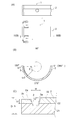
- FIG. 1 is a front view of the sliding bearing 1, where the top and bottom of the screen is the vertical direction, and the front and back directions of the screen are the axial directions (front and back directions).
- the slide bearing 1 is a cylindrical member and is applied to a slide bearing structure of an engine crankshaft 11 as shown in FIG.
- the plain bearing 1 is composed of two halved members 2 and 2.
- the two halved members 2 and 2 have a shape obtained by dividing a cylinder into two in parallel to the axial direction, and are formed so that the cross section is a semicircular shape.
- the half members 2 and 2 are arranged up and down, and mating surfaces are arranged on the left and right.
- FIG. 2 (A) the upper and lower half members 2 are shown.
- the rotation direction of the crankshaft 11 is the clockwise direction when viewed from the front as indicated by the arrow in FIG.
- the bearing angle ⁇ is 0 degree at the right end position in FIG. 2B, and the counterclockwise direction in FIG. 2B is positive. That is, in FIG. 2B, the bearing angle ⁇ at the left end position is defined as 180 degrees, and the bearing angle ⁇ at the lower end position is defined as 270 degrees.
- a groove is provided in the circumferential direction, and a circular hole is provided in the center.
- mating surfaces are arranged on the left and right of the upper half member 2.
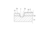
- the half member 2 includes a metal layer 21, a lining layer 22, and a coating layer 23 as shown in FIG.
- a narrow groove 3 is formed at the end in the axial direction.
- the peripheral edge 2a that forms the axially outer side surface of the narrow groove 3 has a height h from the outer peripheral surface of the half member 2 higher than the height D from the outer peripheral surface of the half member 2 to the contact surface. It is formed to be low. That is, the outer peripheral edge 2a in the axial direction is formed to be one step lower than the contact surface with the surrounding crankshaft 11.
- the narrow groove 3 will be described with reference to FIGS. 2 (B) and 2 (C).
- the narrow groove 3 is provided in the lower half member 2.
- two narrow grooves 3 are provided in parallel in the axial direction.
- the narrow groove 3 is formed in a direction in which the bearing angle ⁇ is positive (counterclockwise) from a position (the bearing angle ⁇ is ⁇ 1) that is separated from the mating surface on the downstream side in the rotation direction of the crankshaft 11 (the bearing angle ⁇ is 180 degrees).
- the bearing angle ⁇ is 180 degrees.
- the right mating surface in FIG. 2B is the upstream mating surface in the rotational direction
- the width of the narrow groove 3 is formed to be w as shown in FIG. Further, the depth d of the narrow groove 3 is formed to be shorter than the height D from the outer peripheral surface of the half member 2 to the contact surface.
- peripheral edge 2a is formed so as to be one step higher than the bottom surface 3a of the narrow groove 3, it becomes a wall for preventing oil leaking from the sliding surface to the axial end and oil sucked back from leaking again. , Leakage oil amount can be suppressed. As a result, the amount of oil drawn in particularly during cold can be increased, and the low friction effect due to early temperature rise can be increased.
- peripheral edge portion 2a is formed so as to be one step lower than the contact surface with the surrounding crankshaft 11, the crankshaft 11 is inclined and is in contact with only one end portion in the axial direction. Since the chance of contact between the peripheral edge 2a and the crankshaft 11 can be reduced, damage to the peripheral edge 2a can be prevented.
- the provision of the narrow groove 3 according to the present embodiment increases the FMEP mitigation amount.
- the FMEP reduction amount increases in a region where the engine speed is low.
- FMEP is a value for seeing the tendency of friction, and the friction decreases as the FMEP reduction amount increases. For example, when the engine is cold started, the FMEP mitigation amount increases and friction is reduced.
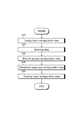
- the manufacturing method of the lower half member 2 includes a lining layer forming step S10 in which the lining layer 22 is pasted on the metal layer 21, a forming step S20 in which the lining layer 22 and the metal layer 21 are formed in a semicircular shape, A narrow groove forming step S30 which is a first step for forming the groove 3, a peripheral portion forming step S40 which is a second step for forming the peripheral portion 2a, and a coating layer 23 shown in FIG. 4 on the surface of the lining layer 22. And a coating layer forming step S50.
- each process is demonstrated concretely.
- the lining layer 22 is attached to the metal layer 21. More specifically, the lining layer 22 is attached to the metal layer 21 by applying a rolling process to the metal layer 21 and the lining layer 22.
- the metal layer 21 is made of a material made of metal, for example, a material made of an iron-based material.
- the lining layer 22 is comprised with the raw material which consists of a metal whose hardness is lower than the metal layer 21, for example, is comprised with the raw material which consists of an aluminum-type material.
- the metal layer 21 and the lining layer 22 are formed in a semicircular shape. More specifically, the metal layer 21 and the lining layer 22 are formed into a semicircular shape by press molding.
- the narrow groove 3 is formed in the narrow groove forming step S30. Further, in the peripheral edge forming step S40, the peripheral edge 2a is formed.
- the depth d of the narrow groove 3 is formed to be longer than the length obtained by subtracting the tolerance a1 of the thickness of the lining layer 22 from the thickness h1 of the lining layer 22.
- the tolerance of the thickness of the lining layer 22 is a1
- the depth of the narrow groove is d
- the depth d of the narrow groove 3 is d> h1-a1.
- the depth d of the narrow groove 3 is longer than the thickness h1 of the lining layer 22, so that the narrow groove 3 is formed from the lining layer 22 to the metal layer 21. For this reason, since the length of the depth d of the narrow groove 3 can be made sufficiently large, the amount of sucked-back oil is increased, and the total amount of spilled oil can be suppressed.
- the peripheral edge forming step S40 since the inner peripheral surface 2c of the peripheral edge 2a is formed on the inner peripheral side with respect to the bottom surface 3a of the narrow groove 3, the peripheral edge 2a is also formed in the lining layer 22. Thereby, when forming the peripheral part 2a, since a blade does not contact the metal layer 21, the lifetime of a blade can be extended.
- the coating layer 23 is formed on the surface (inner peripheral surface) of the lining layer 22.
- the coating layer 23 is made of a material made of a soft metal or a resin material.
- the coating layer 23 is formed by applying on the inner peripheral surface of the lining layer 22. At this time, the coating layer 23 is formed so as to cover the axially inner end portion of the narrow groove 3 as shown in FIG. It is applied to the middle part. With this configuration, the inner end of the narrow groove 3 in the axial direction is covered with the coating layer 23, so that the crankshaft 11 is inclined and comes into contact with only one end in the axial direction (a state where it comes into contact with each other). The friction between the axially inner end of the narrow groove 3 and the crankshaft 11 can be reduced.
- the coating layer 23 can also be formed so as to cover the entire narrow groove 3.
- the cylinder is divided into two parallel to the axial direction, and the half member 2 or 2 having the metal layer 21 and the lining layer 22 provided on the inner peripheral surface of the metal layer 21 is vertically arranged.
- the depth d of the narrow groove 3 is made longer than the thickness h1 of the lining layer 22 minus the tolerance a1 of the thickness of the lining layer 22. Is formed.
- the depth d of the narrow groove 3 is formed to be longer than the thickness h1 of the lining layer 22 minus the tolerance a1 of the thickness of the lining layer 22, so that the lining layer 22 and the metal layer Since the narrow groove 3 can be provided in 21, the amount of sucked-back oil in the narrow groove 3 is increased, and the total amount of spilled oil can be suppressed.
- peripheral part formation process S40 (2nd process) which provides a peripheral part in the axial direction edge part of the lower half member 2, and the axial direction outer side of the narrow groove 3,
- peripheral part formation process S40 The inner peripheral surface 2c of the peripheral edge 2a is formed on the inner peripheral side with respect to the bottom surface 3a of the narrow groove 3.
- the present invention can be used for a technology of a sliding bearing manufacturing method, and can be used for a manufacturing method of a sliding bearing in which a half member in which a cylinder is divided into two in parallel with an axial direction is arranged vertically.
Landscapes
- Engineering & Computer Science (AREA)
- General Engineering & Computer Science (AREA)
- Mechanical Engineering (AREA)
- Chemical & Material Sciences (AREA)
- Oil, Petroleum & Natural Gas (AREA)
- Sliding-Contact Bearings (AREA)
- Shafts, Cranks, Connecting Bars, And Related Bearings (AREA)
Priority Applications (4)
| Application Number | Priority Date | Filing Date | Title |
|---|---|---|---|
| CN201680012098.XA CN107250576A (zh) | 2015-02-27 | 2016-02-26 | 滑动轴承的制造方法以及滑动轴承 |
| EP16755740.4A EP3263924A4 (en) | 2015-02-27 | 2016-02-26 | Method for producing slide bearing, and slide bearing |
| US15/553,738 US20180119739A1 (en) | 2015-02-27 | 2016-02-26 | Sliding bearing manufacturing method and sliding bearing |
| KR1020177026133A KR20170118186A (ko) | 2015-02-27 | 2016-02-26 | 미끄럼 베어링의 제조방법 및 미끄럼 베어링 |
Applications Claiming Priority (2)
| Application Number | Priority Date | Filing Date | Title |
|---|---|---|---|
| JP2015-039116 | 2015-02-27 | ||
| JP2015039116A JP2016161016A (ja) | 2015-02-27 | 2015-02-27 | すべり軸受の製造方法及びすべり軸受 |
Publications (1)
| Publication Number | Publication Date |
|---|---|
| WO2016136996A1 true WO2016136996A1 (ja) | 2016-09-01 |
Family
ID=56789587
Family Applications (1)
| Application Number | Title | Priority Date | Filing Date |
|---|---|---|---|
| PCT/JP2016/055951 WO2016136996A1 (ja) | 2015-02-27 | 2016-02-26 | すべり軸受の製造方法及びすべり軸受 |
Country Status (6)
Families Citing this family (3)
| Publication number | Priority date | Publication date | Assignee | Title |
|---|---|---|---|---|
| JP6893770B2 (ja) * | 2016-10-31 | 2021-06-23 | 大豊工業株式会社 | 半割軸受 |
| JP6773542B2 (ja) * | 2016-12-09 | 2020-10-21 | 大豊工業株式会社 | 半割軸受 |
| KR20190057533A (ko) * | 2017-11-20 | 2019-05-29 | 두산공작기계 주식회사 | 공작 기계용 슬라이드 베어링 |
Citations (2)
| Publication number | Priority date | Publication date | Assignee | Title |
|---|---|---|---|---|
| JP2011237035A (ja) * | 2000-05-03 | 2011-11-24 | Mahle Internatl Gmbh | 軸受 |
| JP2014224601A (ja) * | 2013-04-26 | 2014-12-04 | 大豊工業株式会社 | すべり軸受 |
Family Cites Families (3)
| Publication number | Priority date | Publication date | Assignee | Title |
|---|---|---|---|---|
| US3449028A (en) * | 1965-09-22 | 1969-06-10 | Gen Motors Corp | Anti-cavitation bearing grooving |
| JP5570544B2 (ja) * | 2012-02-29 | 2014-08-13 | 株式会社日立製作所 | すべり軸受装置 |
| JP5837896B2 (ja) * | 2013-03-21 | 2015-12-24 | 大豊工業株式会社 | すべり軸受 |
-
2015
- 2015-02-27 JP JP2015039116A patent/JP2016161016A/ja active Pending
-
2016
- 2016-02-26 KR KR1020177026133A patent/KR20170118186A/ko not_active Ceased
- 2016-02-26 CN CN201680012098.XA patent/CN107250576A/zh active Pending
- 2016-02-26 US US15/553,738 patent/US20180119739A1/en not_active Abandoned
- 2016-02-26 EP EP16755740.4A patent/EP3263924A4/en not_active Withdrawn
- 2016-02-26 WO PCT/JP2016/055951 patent/WO2016136996A1/ja active Application Filing
Patent Citations (2)
| Publication number | Priority date | Publication date | Assignee | Title |
|---|---|---|---|---|
| JP2011237035A (ja) * | 2000-05-03 | 2011-11-24 | Mahle Internatl Gmbh | 軸受 |
| JP2014224601A (ja) * | 2013-04-26 | 2014-12-04 | 大豊工業株式会社 | すべり軸受 |
Non-Patent Citations (1)
| Title |
|---|
| See also references of EP3263924A4 * |
Also Published As
| Publication number | Publication date |
|---|---|
| EP3263924A1 (en) | 2018-01-03 |
| US20180119739A1 (en) | 2018-05-03 |
| KR20170118186A (ko) | 2017-10-24 |
| CN107250576A (zh) | 2017-10-13 |
| JP2016161016A (ja) | 2016-09-05 |
| EP3263924A4 (en) | 2018-10-31 |
Similar Documents
| Publication | Publication Date | Title |
|---|---|---|
| WO2014175426A1 (ja) | すべり軸受 | |
| JP6185853B2 (ja) | すべり軸受 | |
| WO2014148573A1 (ja) | すべり軸受 | |
| WO2016136996A1 (ja) | すべり軸受の製造方法及びすべり軸受 | |
| WO2016136998A1 (ja) | すべり軸受 | |
| WO2016136997A1 (ja) | すべり軸受の製造方法及びすべり軸受 | |
| JP6134636B2 (ja) | すべり軸受 | |
| JP6536774B2 (ja) | すべり軸受 | |
| WO2016136994A1 (ja) | すべり軸受の製造方法及びすべり軸受 | |
| WO2016136995A1 (ja) | すべり軸受 | |
| JP6216226B2 (ja) | すべり軸受 | |
| JP6323833B2 (ja) | すべり軸受 | |
| JP6390852B2 (ja) | すべり軸受 | |
| JP6166064B2 (ja) | すべり軸受 | |
| WO2016136993A1 (ja) | すべり軸受 | |
| JP2019031981A (ja) | すべり軸受 | |
| JP6399576B2 (ja) | すべり軸受 | |
| JP6541144B2 (ja) | すべり軸受 | |
| JP2017110762A (ja) | すべり軸受 | |
| JP2016161011A (ja) | すべり軸受 | |
| JP2017110761A (ja) | すべり軸受 |
Legal Events
| Date | Code | Title | Description |
|---|---|---|---|
| 121 | Ep: the epo has been informed by wipo that ep was designated in this application |
Ref document number: 16755740 Country of ref document: EP Kind code of ref document: A1 |
|
| DPE1 | Request for preliminary examination filed after expiration of 19th month from priority date (pct application filed from 20040101) | ||
| WWE | Wipo information: entry into national phase |
Ref document number: 15553738 Country of ref document: US |
|
| NENP | Non-entry into the national phase |
Ref country code: DE |
|
| REEP | Request for entry into the european phase |
Ref document number: 2016755740 Country of ref document: EP |
|
| ENP | Entry into the national phase |
Ref document number: 20177026133 Country of ref document: KR Kind code of ref document: A |