WO2016136938A1 - 高分子保護材フリー担持触媒の製造方法 - Google Patents
高分子保護材フリー担持触媒の製造方法 Download PDFInfo
- Publication number
- WO2016136938A1 WO2016136938A1 PCT/JP2016/055791 JP2016055791W WO2016136938A1 WO 2016136938 A1 WO2016136938 A1 WO 2016136938A1 JP 2016055791 W JP2016055791 W JP 2016055791W WO 2016136938 A1 WO2016136938 A1 WO 2016136938A1
- Authority
- WO
- WIPO (PCT)
- Prior art keywords
- supported catalyst
- protective material
- polymer protective
- ether
- nanoparticles
- Prior art date
- Legal status (The legal status is an assumption and is not a legal conclusion. Google has not performed a legal analysis and makes no representation as to the accuracy of the status listed.)
- Ceased
Links
Images


Classifications
-
- B—PERFORMING OPERATIONS; TRANSPORTING
- B01—PHYSICAL OR CHEMICAL PROCESSES OR APPARATUS IN GENERAL
- B01J—CHEMICAL OR PHYSICAL PROCESSES, e.g. CATALYSIS OR COLLOID CHEMISTRY; THEIR RELEVANT APPARATUS
- B01J23/00—Catalysts comprising metals or metal oxides or hydroxides, not provided for in group B01J21/00
- B01J23/38—Catalysts comprising metals or metal oxides or hydroxides, not provided for in group B01J21/00 of noble metals
- B01J23/40—Catalysts comprising metals or metal oxides or hydroxides, not provided for in group B01J21/00 of noble metals of the platinum group metals
- B01J23/46—Ruthenium, rhodium, osmium or iridium
-
- B—PERFORMING OPERATIONS; TRANSPORTING
- B01—PHYSICAL OR CHEMICAL PROCESSES OR APPARATUS IN GENERAL
- B01J—CHEMICAL OR PHYSICAL PROCESSES, e.g. CATALYSIS OR COLLOID CHEMISTRY; THEIR RELEVANT APPARATUS
- B01J37/00—Processes, in general, for preparing catalysts; Processes, in general, for activation of catalysts
- B01J37/02—Impregnation, coating or precipitation
-
- H—ELECTRICITY
- H01—ELECTRIC ELEMENTS
- H01M—PROCESSES OR MEANS, e.g. BATTERIES, FOR THE DIRECT CONVERSION OF CHEMICAL ENERGY INTO ELECTRICAL ENERGY
- H01M4/00—Electrodes
- H01M4/86—Inert electrodes with catalytic activity, e.g. for fuel cells
- H01M4/88—Processes of manufacture
-
- H—ELECTRICITY
- H01—ELECTRIC ELEMENTS
- H01M—PROCESSES OR MEANS, e.g. BATTERIES, FOR THE DIRECT CONVERSION OF CHEMICAL ENERGY INTO ELECTRICAL ENERGY
- H01M4/00—Electrodes
- H01M4/86—Inert electrodes with catalytic activity, e.g. for fuel cells
- H01M4/90—Selection of catalytic material
- H01M4/92—Metals of platinum group
-
- Y—GENERAL TAGGING OF NEW TECHNOLOGICAL DEVELOPMENTS; GENERAL TAGGING OF CROSS-SECTIONAL TECHNOLOGIES SPANNING OVER SEVERAL SECTIONS OF THE IPC; TECHNICAL SUBJECTS COVERED BY FORMER USPC CROSS-REFERENCE ART COLLECTIONS [XRACs] AND DIGESTS
- Y02—TECHNOLOGIES OR APPLICATIONS FOR MITIGATION OR ADAPTATION AGAINST CLIMATE CHANGE
- Y02E—REDUCTION OF GREENHOUSE GAS [GHG] EMISSIONS, RELATED TO ENERGY GENERATION, TRANSMISSION OR DISTRIBUTION
- Y02E60/00—Enabling technologies; Technologies with a potential or indirect contribution to GHG emissions mitigation
- Y02E60/30—Hydrogen technology
- Y02E60/50—Fuel cells
Definitions
- the present invention relates to a method for producing a polymer protective material-free supported catalyst in which nanoparticles are supported on a carrier and does not contain a polymer protective material.
- a heterogeneous catalyst in which nanoparticles are supported on a carbon-based carrier is used.
- heterogeneous catalysts in which nanoparticles are supported on a ceramic carrier are used.
- Ru nanoparticles are disclosed as nanoparticles used for heterogeneous catalysts (see, for example, Patent Document 1 or Non-Patent Document 1).
- Non-Patent Document 1 when (fcc) Ru nanoparticles were supported on a carrier and used as a heterogeneous catalyst, the nanoparticles were synthesized and purified using a polymer protective material such as polyvinylpyrrolidone. Nanoparticles are supported on a carrier.
- the polymer protective material used in the synthesis of the nanoparticles remains in the catalyst, the effect of the catalyst may not be fully exhibited. If the purification of the nanoparticles is repeated for the purpose of removing the polymer protective material, the yield of nanoparticles obtained decreases as the number of purification increases.
- An object of the present invention is to produce a polymer protective material-free supported catalyst capable of fully exhibiting the effect of the catalyst without using a polymer protective material that lowers the performance of the catalyst, more efficiently than conventional methods. Is to provide a method.
- the method for producing a polymer protective material-free supported catalyst according to the present invention is a method for producing a polymer protective material-free supported catalyst in which nanoparticles are supported on a carrier and does not contain a polymer protective material, Heating a mixture containing a compound as a synthetic raw material, the support, and an organic solvent having a reducing property having 2 or more carbon atoms and not containing the polymer protective material, In addition to the synthesis, the method has a step 1 of supporting the nanoparticles on the support.
- the boiling point of the organic solvent is preferably 100 ° C. or higher. Excellent handleability.
- the supported catalyst can be obtained more safely.
- the organic solvent is a polyhydric alcohol, butanol, isobutanol, ethoxyethanol, dimethylformamide, xylene, N-methylpyrrolidinone, dichlorobenzene, toluene, propylene glycol.
- Monomethyl ether ethylene glycol monomethyl ether, ethylene glycol monomethyl ether acetate, ethyl lactate, diethylene glycol dimethyl ether, dipropylene glycol dimethyl ether, diethylene glycol ethyl methyl ether, diethylene glycol isopropyl methyl ether, dipropylene glycol monomethyl ether, diethylene glycol diethyl ether, diethylene glycol monomethyl ether, diethylene Guri Butyl methyl ether, tripropylene glycol dimethyl ether, triethylene glycol dimethyl ether, diethylene glycol monobutyl ether, ethylene glycol monophenyl ether, triethylene glycol monomethyl ether, diethylene glycol dibutyl ether, triethylene glycol butyl methyl ether, polyethylene glycol dimethyl ether, tetraethylene glycol It is preferably at least one selected from dimethyl ether and polyethylene glycol monomethyl ether.
- the supported catalyst can be obtained more safely and more efficiently.
- the polyhydric alcohol is preferably at least one selected from ethylene glycol, diethylene glycol, triethylene glycol, propylene glycol and butylene glycol.
- the supported catalyst can be obtained more safely and more efficiently.
- the support includes one or both of carbon and ceramics.
- the support is alumina, silica, silica alumina, calcia, magnesia, titania, ceria, zirconia, ceria zirconia, lantana, lantana alumina, tin oxide, oxidation Tungsten, aluminosilicate, aluminophosphate, borosilicate, phosphotungstic acid, hydroxyapatite, hydrotalcite, perovskite, cordierite, mullite, silicon carbide, activated carbon, carbon black, acetylene black, carbon nanotube and carbon nanohorn The form which is 1 or more types is included.
- the nanoparticles are preferably Ru particles, and the Ru particles preferably have an fcc structure. Compared with a catalyst supporting Ru particles having an hcp structure, a different catalytic activity can be obtained.
- the nanoparticles are preferably Ru particles, and the compound that is a raw material for synthesizing the nanoparticles is preferably a Ru organic compound.
- a supported catalyst can be obtained more efficiently.
- the Ru organic compound is preferably a compound containing diketonate or acetate.
- a supported catalyst can be obtained more efficiently.
- the Ru organic compound is preferably Ru (acac) 3 or Ru acetate.
- a supported catalyst can be obtained more efficiently.
- the present invention provides a production method capable of obtaining a polymer protective material-free supported catalyst capable of fully exhibiting the effect of the catalyst without using a polymer protective material that lowers the performance of the catalyst more efficiently than the conventional method. Can be provided.
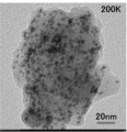
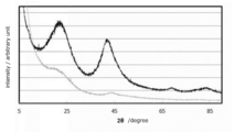
- Example 1A It is a TEM image of Example 1A. It is a TEM image of Example 2A. It is an XRD pattern of Example 1A. It is an XRD pattern of Example 2A.
- the method for producing a polymer protective material-free supported catalyst is a method for producing a polymer protective material-free supported catalyst in which nanoparticles are supported on a carrier and does not contain a polymer protective material. While synthesizing nanoparticles by heating a mixture containing a compound as a raw material for synthesis, a support, and an organic solvent having a reducing property having 2 or more carbon atoms and not containing a polymer protective material And Step 1 of supporting the nanoparticles on the support.
- the method for producing a supported catalyst according to the present embodiment is, for example, that nanoparticle synthesis is performed without using a polymer protective material, and that nanoparticle synthesis and nanoparticle support are performed simultaneously. This is a point different from the conventional manufacturing method described in Patent Document 1. By not using the polymer protective material, it is possible to produce a supported catalyst that can sufficiently exert the action of the catalyst. In addition, by simultaneously performing the synthesis of the nanoparticles and the loading of the nanoparticles on the carrier, the number of manufacturing steps can be reduced as compared with the conventional manufacturing method.
- a nanoparticle means the fine particle whose average particle diameter is 100 nm or less.
- the average particle diameter of the nanoparticles is a value calculated by measuring the particle diameter of at least 100 particles from a particle image obtained by a transmission electron microscope (TEM) and obtaining the average.
- the observation magnification of TEM is preferably 120,000 times or 150,000 times, for example.
- the nanoparticles are, for example, Ru particles, Pd particles, Pt particles, Ir particles, or Au particles.
- the minimum of the average particle diameter of a nanoparticle is not specifically limited, It is preferable that it is 1 nm or more.
- step 1 each substance used in step 1 will be described.
- the synthetic raw material is a Ru compound.
- the Ru compound is preferably a Ru organic compound.
- a supported catalyst can be obtained more efficiently.
- the Ru organic compound is preferably a compound containing diketonate or acetate.
- An example of the Ru organic compound containing diketonate is tris (acetylacetonato) ruthenium (III) (hereinafter referred to as Ru (acac) 3 ).
- the Ru organic compound containing acetate is, for example, ruthenium acetate (hereinafter referred to as Ru acetate).
- the support includes a form that is one or both of carbon and ceramics.
- Ceramics include, for example, alumina, silica, silica alumina, calcia, magnesia, titania, ceria, zirconia, ceria zirconia, lantana, lantana alumina, tin oxide, tungsten oxide, aluminosilicate, aluminophosphate, borosilicate, phosphotungstic acid, hydroxy Apatite, hydrotalcite, perovskite, cordierite, mullite or silicon carbide.
- the carbon is, for example, activated carbon, carbon black, acetylene black, carbon nanotube, or carbon nanohorn.
- only 1 type may be used from these support bodies, or 2 or more types may be used together.
- two or more types are used in combination, two or more types from ceramics may be used in combination, two or more types from carbon may be used in combination, or one or more types from ceramics and one or more types from carbon may be used in combination.
- at least one selected from alumina, silica, titania, ceria, zirconia, activated carbon and carbon black is used.
- Organic solvent has 2 or more carbon atoms and has reducibility. More preferably, the organic solvent has 4 or more carbon atoms.
- the upper limit of the carbon number of the organic solvent is not particularly limited, but is preferably liquid at room temperature.
- the boiling point of the organic solvent is preferably 100 ° C. or higher. Excellent handleability. In addition, the supported catalyst can be obtained more safely.
- the boiling point of the organic solvent is more preferably 160 ° C. or higher.
- the upper limit of the boiling point of the organic solvent is not particularly limited, it is preferably 300 ° C. or lower, more preferably 290 ° C. or lower, from the viewpoint that the solvent can be more easily removed from the supported catalyst.
- Organic solvents are polyhydric alcohol, butanol, isobutanol, ethoxyethanol, dimethylformamide, xylene, N-methylpyrrolidinone, dichlorobenzene, toluene, propylene glycol monomethyl ether, ethylene glycol monomethyl ether, ethylene glycol monomethyl ether acetate, ethyl lactate, Diethylene glycol dimethyl ether, dipropylene glycol dimethyl ether, diethylene glycol ethyl methyl ether, diethylene glycol isopropyl methyl ether, dipropylene glycol monomethyl ether, diethylene glycol diethyl ether, diethylene glycol monomethyl ether, diethylene glycol butyl methyl ether, tripropylene glycol dimethyl Among ether, triethylene glycol dimethyl ether, diethylene glycol monobutyl ether, ethylene glycol monophenyl ether, triethylene glycol monomethyl ether, diethylene glycol dibutyl ether, tri
- the polyhydric alcohol is preferably at least one selected from ethylene glycol, diethylene glycol, triethylene glycol, propylene glycol and butylene glycol. Of these, triethylene glycol is more preferable.
- the supported catalyst can be obtained more safely and more efficiently.
- Polymer protective material In this embodiment, a polymer protective material is not used.
- the polymer protective material is, for example, polyvinyl pyrrolidone (PVP).
- Step 1 will be described taking an example in which the nanoparticles are Ru particles.
- the nanoparticles are Ru particles
- Step 1 includes a Ru compound, a support, and an organic solvent, and a mixture that does not contain a polymer protective material is produced. It is preferable that it is the process of heating after performing.
- step 1 first, a mixture containing a Ru compound, a support, and an organic solvent is prepared.
- concentration of the Ru compound in the mixture is preferably 125 mM (mmol / l) or less, and more preferably 100 mM (mmol / l) or less.
- the ratio between the Ru compound and the support is adjusted so that the amount of Ru particles supported in the supported catalyst falls within a predetermined range.
- the supported amount of Ru particles in the supported catalyst is preferably 0.001 to 60% by mass.
- the supported amount is the ratio of the mass of the nanoparticles to the mass of the supported catalyst in the dry state, and can be measured by, for example, high frequency inductively coupled plasma emission spectrometry or atomic absorption spectrophotometry.
- the Ru compound and the support are suspended in an organic solvent and then dispersed using, for example, a disperser such as an ultrasonic wave.
- a disperser such as an ultrasonic wave.
- the order of addition of each substance is not particularly limited.
- the heating method is not particularly limited, and is, for example, an external heating method such as an oil bath, a mantle heater, a block heater or a heat medium circulation jacket, or a microwave irradiation method.
- the heating temperature is preferably 100 to 300 ° C, more preferably 180 to 230 ° C.
- the rate of temperature rise until reaching the target heating temperature is preferably 4 ° C./min or more, and more preferably 6 ° C./min or more. By setting the temperature rising rate within a predetermined range, Ru particles having an fcc structure can be formed.
- the holding time at the target heating temperature depends on the type of compound used, the amount of liquid in the mixture or the heating temperature, but is preferably 10 to 300 minutes, for example, 120 to 240 minutes. It is more preferable.
- step 1 the Ru compound is reduced by the organic solvent, and Ru particles nucleate and grow on the surface of the support.
- a supported catalyst in which Ru particles are supported on a support is obtained.
- the Ru particles have an fcc structure. Since the Ru particles have an fcc structure, different catalytic activity can be obtained as compared with a catalyst supporting Ru particles having an hcp structure.
- the crystal structure of the Ru particles can be confirmed by, for example, an X-ray diffraction pattern (XRD pattern).
- the average particle size of the Ru particles is preferably 30 nm or less, and more preferably 10 nm or less.
- the lower limit of the average particle diameter of the Ru particles is not particularly limited, but is preferably 1 nm or more.
- the supported catalyst is preferably separated and purified from the solvent.
- the method for separating and purifying the supported catalyst is not particularly limited.
- the method is a method of filtering, washing and drying a mixture having a lowered temperature.
- XRD pattern X-ray diffraction pattern
- Example 1A 125 mL of triethylene glycol (hereinafter, TEG) was charged into the flask.
- TEG triethylene glycol
- 1.9918 g (5 mmol) of tris (acetylacetonato) ruthenium (III) (hereinafter Ru (acac) 3 ) and 4.5031 g of activated carbon (FAM-50, manufactured by Nippon Enviro Chemicals) were weighed. And mixed with an ultrasonic wave for 30 minutes to prepare a mixed solution. The polymer protective material was not added to the mixed solution.
- the mixture was heated to 200 ° C. at a rate of temperature increase of 6 ° C./min, heated and stirred at 200 ° C. for 3 hours, and then cooled.
- the cooled mixture was filtered under reduced pressure, and the solid component (filtered material) was thoroughly washed with ethanol and then dried under reduced pressure to obtain a supported catalyst.
- Example 2A 40 mL of TEG was charged into the flask. 1.9920 g (5 mmol) of Ru (acac) 3 and 4.5022 g of activated carbon (FAM-50) were weighed and added to the TEG, and dispersed by ultrasonication for 30 min to prepare a mixed solution. The polymer protective material was not added to the mixed solution. The mixture was heated to 200 ° C. at a rate of temperature increase of 6 ° C./min, heated and stirred at 200 ° C. for 3 hours, and then cooled. The cooled mixture was filtered under reduced pressure, and the solid component (filtered material) was thoroughly washed with ethanol and then dried under reduced pressure to obtain a supported catalyst.
- Ru acac
- FAM-50 activated carbon
- Example 3A 185 mL of TEG was charged into the flask. 5.9056 g (14.8 mmol) of Ru (acac) 3 and 4.5022 g of Ketjen Black (EC300J, manufactured by Lion Corporation) are weighed and added to the TEG, and dispersed by mixing with ultrasonic waves for 30 min. Was made. The polymer protective material was not added to the mixed solution. The mixture was heated to 200 ° C. at a rate of temperature increase of 6 ° C./min, heated and stirred at 200 ° C. for 3 hours, and then cooled. The cooled mixture was filtered under reduced pressure, and the solid component (filtered material) was thoroughly washed with ethanol and then dried under reduced pressure to obtain a supported catalyst.
- Example 4A 125 mL of TEG was charged into the flask. 0.9869 g (2.5 mmol) of Ru (acac) 3 and 4.796 g of activated carbon (FAM-50) were weighed and added to the TEG, and dispersed for 30 min with ultrasound to prepare a mixed solution. . The polymer protective material was not added to the mixed solution. The mixture was heated to 200 ° C. at a rate of temperature increase of 6 ° C./min, heated and stirred at 200 ° C. for 3 hours, and then cooled. The solid component was precipitated from the cooled mixed solution using centrifugal separation, the supernatant was removed, the solid component was sufficiently washed with ethanol, and then dried under reduced pressure to obtain a supported catalyst.
- Ru acac
- FAM-50 activated carbon
- Example 1A Average particle diameter of Ru particles
- Example 2A Average particle diameter of Ru particles
- the supported catalysts of Example 1A and Example 2A were observed with a TEM at a magnification of 150,000 times and 200000 times, respectively, and the particle diameter of 100 particles was measured from the obtained particle images, the average was obtained, and the average of Ru particles The particle diameter was taken.
- FIG. 1 shows a TEM image of Example 1A
- FIG. 2 shows a TEM image of Example 2A.
- the average particle size of Example 1A was 3.34 nm
- the average particle size of Example 2A was 3.14 nm. Further, from FIG. 1 and FIG. 2, the presence of aggregated particles was not confirmed.
- Example 1A (Crystal state) XRD measurement was performed on the supported catalysts of Example 1A and Example 2A.
- FIG. 3 shows the XRD pattern of Example 1A
- FIG. 4 shows the XRD pattern of Example 2A.
- the Ru pattern shows the (fcc) Ru pattern, and it was confirmed that the Ru particles have the fcc structure.
- the pattern of Ru includes a pattern of (fcc) Ru and a pattern of (hcp) Ru.
Landscapes
- Chemical & Material Sciences (AREA)
- Engineering & Computer Science (AREA)
- Materials Engineering (AREA)
- Organic Chemistry (AREA)
- Chemical Kinetics & Catalysis (AREA)
- Catalysts (AREA)
- Inert Electrodes (AREA)
Abstract
本発明の目的は、触媒の性能を低下させる高分子保護材を用いず、触媒の効果を十分に発揮できる高分子保護材フリー担持触媒を、従来の方法よりも効率的に得ることができる製造方法を提供することである。本発明に係る高分子保護材フリー担持触媒の製造方法は、ナノ粒子が担持体に担持され、高分子保護材を含有しない高分子保護材フリー担持触媒の製造方法であって、ナノ粒子の合成原料となる化合物と、担持体と、炭素数が2以上の還元性をもつ有機溶媒と、を含有し、かつ、高分子保護材を含有しない混合物を加熱して、ナノ粒子を合成するとともに、該ナノ粒子を前記担持体に担持させる工程1を有する。
Description
本発明は、ナノ粒子が担持体に担持され、高分子保護材を含有しない高分子保護材フリー担持触媒の製造方法に関する。
従来、化学反応触媒又は燃料電池などでは、カーボン系の担体にナノ粒子を担持した不均一系触媒が用いられている。また、ボイラー又は排ガスの浄化などでは、セラミックス系の担体にナノ粒子を担持した不均一系触媒が用いられている。不均一系触媒に用いるナノ粒子として(fcc)Ruナノ粒子が開示されている(例えば、特許文献1、又は非特許文献1を参照。)。非特許文献1では、(fcc)Ruナノ粒子を担体に担持して不均一系触媒として使用する場合、ポリビニルピロリドンなどの高分子保護材を用いてナノ粒子を合成・精製した後に、得られたナノ粒子を担体に担持している。
J.Am.Chem.Soc.,2013,135(15),pp5493-5496
しかし、ナノ粒子の合成時に用いた高分子保護材が触媒中に残っていると、触媒の効果が十分に発揮されない場合がある。高分子保護材の除去を目的としてナノ粒子の精製を繰り返すと、精製回数が増加するにつれて得られるナノ粒子の収量が少なくなるという問題である。
本発明の目的は、触媒の性能を低下させる高分子保護材を用いず、触媒の効果を十分に発揮できる高分子保護材フリー担持触媒を、従来の方法よりも効率的に得ることができる製造方法を提供することである。
本発明に係る高分子保護材フリー担持触媒の製造方法は、ナノ粒子が担持体に担持され、高分子保護材を含有しない高分子保護材フリー担持触媒の製造方法であって、前記ナノ粒子の合成原料となる化合物と、前記担持体と、炭素数が2以上の還元性をもつ有機溶媒と、を含有し、かつ、前記高分子保護材を含有しない混合物を加熱して、前記ナノ粒子を合成するとともに、該ナノ粒子を前記担持体に担持させる工程1を有することを特徴とする。
本発明に係る高分子保護材フリー担持触媒の製造方法では、前記有機溶媒の沸点は100℃以上であることが好ましい。取り扱い性に優れる。また、担持触媒をより安全に得ることができる。
本発明に係る高分子保護材フリー担持触媒の製造方法では、前記有機溶媒は、多価アルコール、ブタノール、イソブタノール、エトキシエタノール、ジメチルホルムアミド、キシレン、N-メチルピロリジノン、ジクロロベンゼン、トルエン、プロピレングリコールモノメチルエーテル、エチレングリコールモノメチルエーテル、エチレングリコールモノメチルエーテルアセテート、エチルラクテート、ジエチレングリコールジメチルエーテル、ジプロピレングリコールジメチルエーテル、ジエチレングリコールエチルメチルエーテル、ジエチレングリコールイソプロピルメチルエーテル、ジプロピレングリコールモノメチルエーテル、ジエチレングリコールジエチルエーテル、ジエチレングリコールモノメチルエーテル、ジエチレングリコールブチルメチルエーテル、トリプロピレングリコールジメチルエーテル、トリエチレングリコールジメチルエーテル、ジエチレングリコールモノブチルエーテル、エチレングリコールモノフェニルエーテル、トリエチレングリコールモノメチルエーテル、ジエチレングリコールジブチルエーテル、トリエチレングリコールブチルメチルエーテル、ポリエチレングリコールジメチルエーテル、テトラエチレングリコールジメチルエーテル及びポリエチレングリコールモノメチルエーテルの中から選ばれる1種以上であることが好ましい。担持触媒をより安全、かつ、より効率的に得ることができる。
本発明に係る高分子保護材フリー担持触媒の製造方法では、前記多価アルコールは、エチレングリコール、ジエチレングリコール、トリエチレングリコール、プロピレングリコール及びブチレングリコールの中から選ばれる1種以上であることが好ましい。担持触媒をより安全、かつ、より効率的に得ることができる。
本発明に係る高分子保護材フリー担持触媒の製造方法では、前記担持体は、カーボン若しくはセラミックスのいずれか一方又は両方である形態を包含する。
本発明に係る高分子保護材フリー担持触媒の製造方法では、前記担持体は、アルミナ、シリカ、シリカアルミナ、カルシア、マグネシア、チタニア、セリア、ジルコニア、セリアジルコニア、ランタナ、ランタナアルミナ、酸化スズ、酸化タングステン、アルミノシリケート、アルミノホスフェート、ボロシリケート、リンタングステン酸、ヒドロキシアパタイト、ハイドロタルサイト、ペロブスカイト、コージェライト、ムライト、シリコンカーバイド、活性炭、カーボンブラック、アセチレンブラック、カーボンナノチューブ及びカーボンナノホーンの中から選ばれる1種以上である形態を包含する。
本発明に係る高分子保護材フリー担持触媒の製造方法では、前記ナノ粒子がRu粒子であり、該Ru粒子はfcc構造を有していることが好ましい。hcp構造を有するRu粒子を担持させた触媒と比較し、異なる触媒活性を得ることができる。
本発明に係る高分子保護材フリー担持触媒の製造方法では、前記ナノ粒子がRu粒子であり、前記ナノ粒子の合成原料となる化合物はRu有機化合物であることが好ましい。担持触媒をより効率的に得ることができる。
本発明に係る高分子保護材フリー担持触媒の製造方法では、前記Ru有機化合物は、ジケトナート又はアセテートを含有する化合物であることが好ましい。担持触媒をより効率的に得ることができる。
本発明に係る高分子保護材フリー担持触媒の製造方法では、前記Ru有機化合物がRu(acac)3又は酢酸Ruであることが好ましい。担持触媒をより効率的に得ることができる。
本発明は、触媒の性能を低下させる高分子保護材を用いず、触媒の効果を十分に発揮できる高分子保護材フリー担持触媒を、従来の方法よりも効率的に得ることができる製造方法を提供することができる。
次に本発明について実施形態を示して詳細に説明するが本発明はこれらの記載に限定して解釈されない。本発明の効果を奏する限り、実施形態は種々の変形をしてもよい。
本実施形態に係る高分子保護材フリー担持触媒の製造方法は、ナノ粒子が担持体に担持され、高分子保護材を含有しない高分子保護材フリー担持触媒の製造方法であって、ナノ粒子の合成原料となる化合物と、担持体と、炭素数が2以上の還元性をもつ有機溶媒と、を含有し、かつ、高分子保護材を含有しない混合物を加熱して、ナノ粒子を合成するとともに、該ナノ粒子を前記担持体に担持させる工程1を有する。
本実施形態に係る担持触媒の製造方法は、高分子保護材を用いずにナノ粒子を合成する点、及びナノ粒子の合成とナノ粒子の担持体への担持とを同時に行う点が、例えば非特許文献1に記載されたような従来の製造方法と異なる点である。高分子保護材を用いないことで、触媒の作用を十分の発揮させることができる担持触媒を製造することができる。また、ナノ粒子の合成とナノ粒子の担持体への担持とを同時に行うことで、従来の製造方法と比較して製造工程を少なくすることができる。本明細書において、ナノ粒子とは、平均粒子径が100nm以下の微細粒子をいう。ナノ粒子の平均粒子径は、透過型電子顕微鏡(TEM)によって得られた粒子像から少なくとも100個以上の粒子の粒子径を計測し、その平均を求めることによって算出した値である。TEMの観察倍率は、例えば、120000倍又は150000倍であることが好ましい。ナノ粒子は、例えば、Ru粒子、Pd粒子、Pt粒子、Ir粒子又はAu粒子である。ナノ粒子の平均粒子径の下限は、特に限定されないが、1nm以上であることが好ましい。
次に、工程1で用いる各物質について説明する。
(ナノ粒子の合成原料となる化合物)
本実施形態に係る高分子保護材フリー担持触媒の製造方法では、ナノ粒子がRu粒子であるとき、合成原料はRu化合物である。Ru化合物はRu有機化合物であることが好ましい。担持触媒をより効率的に得ることができる。Ru有機化合物は、ジケトナート又はアセテートを含有する化合物であることが好ましい。ジケトナートを含有するRu有機化合物は、例えば、トリス(アセチルアセトナト)ルテニウム(III)(以降、Ru(acac)3という。)である。アセテートを含有するRu有機化合物は、例えば、酢酸ルテニウム(以降、酢酸Ruという。)である。
本実施形態に係る高分子保護材フリー担持触媒の製造方法では、ナノ粒子がRu粒子であるとき、合成原料はRu化合物である。Ru化合物はRu有機化合物であることが好ましい。担持触媒をより効率的に得ることができる。Ru有機化合物は、ジケトナート又はアセテートを含有する化合物であることが好ましい。ジケトナートを含有するRu有機化合物は、例えば、トリス(アセチルアセトナト)ルテニウム(III)(以降、Ru(acac)3という。)である。アセテートを含有するRu有機化合物は、例えば、酢酸ルテニウム(以降、酢酸Ruという。)である。
(担持体)
担持体は、カーボン若しくはセラミックスのいずれか一方又は両方である形態を包含する。セラミックスは、例えば、アルミナ、シリカ、シリカアルミナ、カルシア、マグネシア、チタニア、セリア、ジルコニア、セリアジルコニア、ランタナ、ランタナアルミナ、酸化スズ、酸化タングステン、アルミノシリケート、アルミノホスフェート、ボロシリケート、リンタングステン酸、ヒドロキシアパタイト、ハイドロタルサイト、ペロブスカイト、コージェライト、ムライト又はシリコンカーバイドである。カーボンは、例えば、活性炭、カーボンブラック、アセチレンブラック、カーボンナノチューブ又はカーボンナノホーンである。本実施形態では、これらの担持体の中から1種だけを使用するか、又は2種以上を併用してもよい。2種以上を併用する場合は、セラミックスから2種以上を組合せて用いるか、カーボンから2種以上を組合せて用いるか、又はセラミックスから1種以上及びカーボンから1種以上を組合せて用いてもよい。より好ましくは、アルミナ、シリカ、チタニア、セリア、ジルコニア、活性炭及びカーボンブラックの中から選ばれる1種以上を用いる。
担持体は、カーボン若しくはセラミックスのいずれか一方又は両方である形態を包含する。セラミックスは、例えば、アルミナ、シリカ、シリカアルミナ、カルシア、マグネシア、チタニア、セリア、ジルコニア、セリアジルコニア、ランタナ、ランタナアルミナ、酸化スズ、酸化タングステン、アルミノシリケート、アルミノホスフェート、ボロシリケート、リンタングステン酸、ヒドロキシアパタイト、ハイドロタルサイト、ペロブスカイト、コージェライト、ムライト又はシリコンカーバイドである。カーボンは、例えば、活性炭、カーボンブラック、アセチレンブラック、カーボンナノチューブ又はカーボンナノホーンである。本実施形態では、これらの担持体の中から1種だけを使用するか、又は2種以上を併用してもよい。2種以上を併用する場合は、セラミックスから2種以上を組合せて用いるか、カーボンから2種以上を組合せて用いるか、又はセラミックスから1種以上及びカーボンから1種以上を組合せて用いてもよい。より好ましくは、アルミナ、シリカ、チタニア、セリア、ジルコニア、活性炭及びカーボンブラックの中から選ばれる1種以上を用いる。
(有機溶媒)
有機溶媒は、炭素数が2以上であり、還元性をもつ。有機溶媒の炭素数は、4以上であることがより好ましい。有機溶媒の炭素数の上限は、特に限定されないが、常温において液体であることが望ましい。
有機溶媒は、炭素数が2以上であり、還元性をもつ。有機溶媒の炭素数は、4以上であることがより好ましい。有機溶媒の炭素数の上限は、特に限定されないが、常温において液体であることが望ましい。
有機溶媒の沸点は100℃以上であることが好ましい。取り扱い性に優れる。また、担持触媒をより安全に得ることができる。有機溶媒の沸点は、160℃以上であることがより好ましい。有機溶媒の沸点の上限は、特に限定されないが、担持触媒から溶媒をより容易に除去できる点で、300℃以下であることが好ましく、290℃以下であることがより好ましい。
有機溶媒は、多価アルコール、ブタノール、イソブタノール、エトキシエタノール、ジメチルホルムアミド、キシレン、N-メチルピロリジノン、ジクロロベンゼン、トルエン、プロピレングリコールモノメチルエーテル、エチレングリコールモノメチルエーテル、エチレングリコールモノメチルエーテルアセテート、エチルラクテート、ジエチレングリコールジメチルエーテル、ジプロピレングリコールジメチルエーテル、ジエチレングリコールエチルメチルエーテル、ジエチレングリコールイソプロピルメチルエーテル、ジプロピレングリコールモノメチルエーテル、ジエチレングリコールジエチルエーテル、ジエチレングリコールモノメチルエーテル、ジエチレングリコールブチルメチルエーテル、トリプロピレングリコールジメチルエーテル、トリエチレングリコールジメチルエーテル、ジエチレングリコールモノブチルエーテル、エチレングリコールモノフェニルエーテル、トリエチレングリコールモノメチルエーテル、ジエチレングリコールジブチルエーテル、トリエチレングリコールブチルメチルエーテル、ポリエチレングリコールジメチルエーテル、テトラエチレングリコールジメチルエーテル及びポリエチレングリコールモノメチルエーテルの中から選ばれる1種以上であることが好ましい。担持触媒をより安全、かつ、より効率的に得ることができる。このうち、多価アルコールがより好ましい。
多価アルコールは、エチレングリコール、ジエチレングリコール、トリエチレングリコール、プロピレングリコール及びブチレングリコールの中から選ばれる1種以上であることが好ましい。このうち、トリエチレングリコールがより好ましい。担持触媒をより安全、かつ、より効率的に得ることができる。
(高分子保護材)
本実施形態では、高分子保護材を用いない。高分子保護材は、例えば、ポリビニルピロリドン(PVP)である。
本実施形態では、高分子保護材を用いない。高分子保護材は、例えば、ポリビニルピロリドン(PVP)である。
次に、工程1について、ナノ粒子がRu粒子である形態を例にとって説明する。
本実施形態に係る担持触媒の製造方法では、ナノ粒子がRu粒子であり、工程1が、Ru化合物と、担持体と、有機溶媒と、を含有し、高分子保護材を含有しない混合物を作製した後に加熱する工程であることが好ましい。
工程1では、まず、Ru化合物と、担持体と、有機溶媒と、を含有する混合物を作製する。混合物中のRu化合物の濃度は、125mM(mmol/l)以下であることが好ましく、100mM(mmol/l)以下であることがより好ましい。また、Ru化合物と担持体との割合は、担持触媒中のRu粒子の担持量が所定の範囲となるように調整する。担持触媒中のRu粒子の担持量は、0.001~60質量%であることが好ましい。ここで、担持量は、乾燥状態の担持触媒の質量に対するナノ粒子の質量の割合であり、例えば高周波誘導結合プラズマ発光分光分析又は原子吸光分光光度分析で測定することができる。
混合物の作製にあたり、Ru化合物及び担持体を有機溶媒中に懸濁させた後、例えば超音波などの分散機を用いて分散させることが好ましい。本発明は、各物質の添加順は特に限定されない。
次いで、混合物を加熱する。加熱方法は、特に限定されず、例えば、オイルバス、マントルヒーター、ブロックヒーター若しくは熱媒循環式ジャケットなどの外部加熱方式、又はマイクロ波照射方式である。加熱温度は、100~300℃であることが好ましく、180~230℃であることがより好ましい。目的とする加熱温度に到達させるまでの昇温速度は、4℃/分以上であることが好ましく、6℃/分以上であることがより好ましい。昇温速度を所定の範囲とすることで、fcc構造を有するRu粒子を形成することができる。また、目的とする加熱温度で保持する時間は、使用する化合物の種類、混合物の液量又は加熱温度などに依存するが、例えば、10~300分であることが好ましく、120~240分であることがより好ましい。
工程1では、Ru化合物が有機溶媒によって還元され、担持体の表面でRu粒子の核生成及び粒成長が起こる。そして、Ru粒子が担持体に担持された担持触媒が得られる。このRu粒子はfcc構造を有している。Ru粒子がfcc構造を有することで、hcp構造を有するRu粒子を担持させた触媒と比較し、異なる触媒活性を得ることができる。Ru粒子の結晶構造は、例えば、X線回折パターン(XRDパターン)によって確認できる。Ru粒子の平均粒子径は、30nm以下であることが好ましく、10nm以下であることがより好ましい。Ru粒子の平均粒子径の下限は、特に限定されないが、1nm以上であることが好ましい。
工程1の後、担持触媒を溶媒から分離精製することが好ましい。担持触媒を分離精製する方法は、特に限定されないが、例えば、温度が下がった混合物をろ過し、洗浄・乾燥する方法である。
本実施形態に係る製造方法で得られた担持触媒は、担持触媒の外表面に高分子保護材が存在しない。また、ナノ粒子と担持体との間に高分子保護材が介在しないことが好ましい。担持触媒が高分子保護材を含有するか否かは、例えば、X線回折パターン(XRDパターン)によって確認できる。例えば高分子保護材がPVPであるとき、室温でλ=CuKαの測定条件で測定したXRDパターンにおいて、10°付近にPVP由来のパターンの有無によって確認することができる。
以降、実施例を示しながら本発明についてさらに詳細に説明するが、本発明は実施例に限定して解釈されない。
(実施例1A)
フラスコにトリエチレングリコール(以下、TEG)を125mL投入した。トリス(アセチルアセトナト)ルテニウム(III)(以下、Ru(acac)3)を1.9918g(5mmol)と活性炭(FAM-50、日本エンバイロケミカルズ社製)を4.5031gとを秤とり前記TEG中に添加し、超音波で30min分散して混合液を作製した。混合液に高分子保護材は添加しなかった。この混合液を6℃/分の昇温速度で200℃まで加熱し、200℃で3hr加熱撹拌し、その後冷却した。冷却した混合液を減圧ろ過し、固体成分(濾物)をエタノールで十分に洗浄した後減圧乾燥を実施し、担持触媒を得た。
フラスコにトリエチレングリコール(以下、TEG)を125mL投入した。トリス(アセチルアセトナト)ルテニウム(III)(以下、Ru(acac)3)を1.9918g(5mmol)と活性炭(FAM-50、日本エンバイロケミカルズ社製)を4.5031gとを秤とり前記TEG中に添加し、超音波で30min分散して混合液を作製した。混合液に高分子保護材は添加しなかった。この混合液を6℃/分の昇温速度で200℃まで加熱し、200℃で3hr加熱撹拌し、その後冷却した。冷却した混合液を減圧ろ過し、固体成分(濾物)をエタノールで十分に洗浄した後減圧乾燥を実施し、担持触媒を得た。
(実施例2A)
フラスコにTEGを40mL投入した。Ru(acac)3を1.9920g(5mmol)と活性炭(FAM-50)を4.5022gとを秤とり前記TEG中に添加し、超音波で30min分散して混合液を作製した。混合液に高分子保護材は添加しなかった。この混合液を6℃/分の昇温速度で200℃まで加熱し、200℃で3hr加熱撹拌し、その後冷却した。冷却した混合液を減圧ろ過し、固体成分(濾物)をエタノールで十分に洗浄した後減圧乾燥を実施し、担持触媒を得た。
フラスコにTEGを40mL投入した。Ru(acac)3を1.9920g(5mmol)と活性炭(FAM-50)を4.5022gとを秤とり前記TEG中に添加し、超音波で30min分散して混合液を作製した。混合液に高分子保護材は添加しなかった。この混合液を6℃/分の昇温速度で200℃まで加熱し、200℃で3hr加熱撹拌し、その後冷却した。冷却した混合液を減圧ろ過し、固体成分(濾物)をエタノールで十分に洗浄した後減圧乾燥を実施し、担持触媒を得た。
(実施例3A)
フラスコにTEGを185mL投入した。Ru(acac)3を5.9056g(14.8mmol)とケッチェンブラック(EC300J、ライオン社製)とを4.5022g秤とり前記TEG中に添加し、超音波で30minの間分散して混合液を作製した。混合液に高分子保護材は添加しなかった。この混合液を6℃/分の昇温速度で200℃まで加熱し、200℃で3hr加熱撹拌し、その後冷却した。冷却した混合液を減圧ろ過し、固体成分(濾物)をエタノールで十分に洗浄した後減圧乾燥を実施し、担持触媒を得た。
フラスコにTEGを185mL投入した。Ru(acac)3を5.9056g(14.8mmol)とケッチェンブラック(EC300J、ライオン社製)とを4.5022g秤とり前記TEG中に添加し、超音波で30minの間分散して混合液を作製した。混合液に高分子保護材は添加しなかった。この混合液を6℃/分の昇温速度で200℃まで加熱し、200℃で3hr加熱撹拌し、その後冷却した。冷却した混合液を減圧ろ過し、固体成分(濾物)をエタノールで十分に洗浄した後減圧乾燥を実施し、担持触媒を得た。
(実施例4A)
フラスコにTEGを125mL投入した。Ru(acac)3を0.9869g(2.5mmol)と活性炭(FAM-50)を4.7496gとを秤とり前記TEG中に添加し、超音波で30minの間分散して混合液を作製した。混合液に高分子保護材は添加しなかった。この混合液を6℃/分の昇温速度で200℃まで加熱し、200℃で3hr加熱撹拌し、その後冷却した。遠心分離を用いて冷却後の混合液から固体成分を沈降させ上澄みを除去し、固体成分をエタノールで十分に洗浄した後減圧乾燥を実施し、担持触媒を得た。
フラスコにTEGを125mL投入した。Ru(acac)3を0.9869g(2.5mmol)と活性炭(FAM-50)を4.7496gとを秤とり前記TEG中に添加し、超音波で30minの間分散して混合液を作製した。混合液に高分子保護材は添加しなかった。この混合液を6℃/分の昇温速度で200℃まで加熱し、200℃で3hr加熱撹拌し、その後冷却した。遠心分離を用いて冷却後の混合液から固体成分を沈降させ上澄みを除去し、固体成分をエタノールで十分に洗浄した後減圧乾燥を実施し、担持触媒を得た。
(Ru粒子の平均粒子径)
実施例1A及び実施例2Aの担持触媒をTEMでそれぞれ倍率150000倍、200000倍で観察し、得られた粒子像から100個の粒子の粒子径を計測し、その平均を求め、Ru粒子の平均粒子径とした。図1に実施例1AのTEM像を、図2に実施例2AのTEM像を示す。実施例1Aの平均粒子径は3.34nm、実施例2Aの平均粒子径は3.14nmであった。また、図1及び図2から、凝集した粒子の存在は確認されなかった。
実施例1A及び実施例2Aの担持触媒をTEMでそれぞれ倍率150000倍、200000倍で観察し、得られた粒子像から100個の粒子の粒子径を計測し、その平均を求め、Ru粒子の平均粒子径とした。図1に実施例1AのTEM像を、図2に実施例2AのTEM像を示す。実施例1Aの平均粒子径は3.34nm、実施例2Aの平均粒子径は3.14nmであった。また、図1及び図2から、凝集した粒子の存在は確認されなかった。
(結晶状態)
実施例1A及び実施例2Aの担持触媒について、XRD測定を行った。XRD測定条件は、室温でλ=CuKαである。図3に実施例1AのXRDパターンを、図4に実施例2AのXRDパターンを示す。図3において、Ruのパターンは(fcc)Ruのパターンを示しており、Ru粒子がfcc構造を有することが確認できた。図4において、Ruのパターンは(fcc)Ruのパターン及び(hcp)Ruのパターンを含むことが示されていた。
実施例1A及び実施例2Aの担持触媒について、XRD測定を行った。XRD測定条件は、室温でλ=CuKαである。図3に実施例1AのXRDパターンを、図4に実施例2AのXRDパターンを示す。図3において、Ruのパターンは(fcc)Ruのパターンを示しており、Ru粒子がfcc構造を有することが確認できた。図4において、Ruのパターンは(fcc)Ruのパターン及び(hcp)Ruのパターンを含むことが示されていた。
Claims (10)
- ナノ粒子が担持体に担持され、高分子保護材を含有しない高分子保護材フリー担持触媒の製造方法であって、
前記ナノ粒子の合成原料となる化合物と、前記担持体と、炭素数が2以上の還元性をもつ有機溶媒と、を含有し、かつ、前記高分子保護材を含有しない混合物を加熱して、前記ナノ粒子を合成するとともに、該ナノ粒子を前記担持体に担持させる工程1を有することを特徴とする高分子保護材フリー担持触媒の製造方法。 - 前記有機溶媒の沸点は100℃以上であることを特徴とする請求項1に記載の高分子保護材フリー担持触媒の製造方法。
- 前記有機溶媒は、多価アルコール、ブタノール、イソブタノール、エトキシエタノール、ジメチルホルムアミド、キシレン、N-メチルピロリジノン、ジクロロベンゼン、トルエン、プロピレングリコールモノメチルエーテル、エチレングリコールモノメチルエーテル、エチレングリコールモノメチルエーテルアセテート、エチルラクテート、ジエチレングリコールジメチルエーテル、ジプロピレングリコールジメチルエーテル、ジエチレングリコールエチルメチルエーテル、ジエチレングリコールイソプロピルメチルエーテル、ジプロピレングリコールモノメチルエーテル、ジエチレングリコールジエチルエーテル、ジエチレングリコールモノメチルエーテル、ジエチレングリコールブチルメチルエーテル、トリプロピレングリコールジメチルエーテル、トリエチレングリコールジメチルエーテル、ジエチレングリコールモノブチルエーテル、エチレングリコールモノフェニルエーテル、トリエチレングリコールモノメチルエーテル、ジエチレングリコールジブチルエーテル、トリエチレングリコールブチルメチルエーテル、ポリエチレングリコールジメチルエーテル、テトラエチレングリコールジメチルエーテル及びポリエチレングリコールモノメチルエーテルの中から選ばれる1種以上であることを特徴とする請求項1又は2に記載の高分子保護材フリー担持触媒の製造方法。
- 前記多価アルコールは、エチレングリコール、ジエチレングリコール、トリエチレングリコール、プロピレングリコール及びブチレングリコールの中から選ばれる1種以上であることを特徴とする請求項3に記載の高分子保護材フリー担持触媒の製造方法。
- 前記担持体は、カーボン若しくはセラミックスのいずれか一方又は両方であることを特徴とする請求項1~4のいずれか一つに記載の高分子保護材フリー担持触媒の製造方法。
- 前記担持体は、アルミナ、シリカ、シリカアルミナ、カルシア、マグネシア、チタニア、セリア、ジルコニア、セリアジルコニア、ランタナ、ランタナアルミナ、酸化スズ、酸化タングステン、アルミノシリケート、アルミノホスフェート、ボロシリケート、リンタングステン酸、ヒドロキシアパタイト、ハイドロタルサイト、ペロブスカイト、コージェライト、ムライト、シリコンカーバイド、活性炭、カーボンブラック、アセチレンブラック、カーボンナノチューブ及びカーボンナノホーンの中から選ばれる1種以上であることを特徴とする請求項1~5のいずれか一つに記載の高分子保護材フリー担持触媒の製造方法。
- 前記ナノ粒子がRu粒子であり、該Ru粒子はfcc構造を有していることを特徴とする請求項1~6のいずれか一つに記載の高分子保護材フリー担持触媒の製造方法。
- 前記ナノ粒子がRu粒子であり、前記ナノ粒子の合成原料となる化合物はRu有機化合物であることを特徴とする請求項1~7のいずれか一つに記載の高分子保護材フリー担持触媒の製造方法。
- 前記Ru有機化合物は、ジケトナート又はアセテートを含有する化合物であることを特徴とする請求項8に記載の高分子保護材フリー担持触媒の製造方法。
- 前記Ru有機化合物がRu(acac)3又は酢酸Ruであることを特徴とする請求項8に記載の高分子保護材フリー担持触媒の製造方法。
Applications Claiming Priority (2)
| Application Number | Priority Date | Filing Date | Title |
|---|---|---|---|
| JP2015-039661 | 2015-02-28 | ||
| JP2015039661A JP6761998B2 (ja) | 2015-02-28 | 2015-02-28 | 高分子保護材フリー担持触媒の製造方法 |
Publications (1)
| Publication Number | Publication Date |
|---|---|
| WO2016136938A1 true WO2016136938A1 (ja) | 2016-09-01 |
Family
ID=56789436
Family Applications (1)
| Application Number | Title | Priority Date | Filing Date |
|---|---|---|---|
| PCT/JP2016/055791 Ceased WO2016136938A1 (ja) | 2015-02-28 | 2016-02-26 | 高分子保護材フリー担持触媒の製造方法 |
Country Status (2)
| Country | Link |
|---|---|
| JP (1) | JP6761998B2 (ja) |
| WO (1) | WO2016136938A1 (ja) |
Citations (6)
| Publication number | Priority date | Publication date | Assignee | Title |
|---|---|---|---|---|
| JPH01307445A (ja) * | 1988-06-02 | 1989-12-12 | Matsushita Electric Ind Co Ltd | 触媒調整法 |
| JPH0360534B2 (ja) * | 1981-01-29 | 1991-09-17 | Kogyo Gijutsuin | |
| JP2005515063A (ja) * | 2001-12-03 | 2005-05-26 | スリーエム イノベイティブ プロパティズ カンパニー | 担持されたナノ粒子触媒 |
| JP2008049336A (ja) * | 2006-07-26 | 2008-03-06 | Nippon Shokubai Co Ltd | 金属担持触媒の製法 |
| WO2013038674A1 (ja) * | 2011-09-16 | 2013-03-21 | 独立行政法人科学技術振興機構 | 実質的に面心立方構造を有するルテニウム微粒子およびその製造方法 |
| JP2015090855A (ja) * | 2013-11-07 | 2015-05-11 | 国立大学法人北陸先端科学技術大学院大学 | 金属ナノ粒子担持炭素材料およびその製造方法、官能化剥離炭素材料の製造方法 |
Family Cites Families (2)
| Publication number | Priority date | Publication date | Assignee | Title |
|---|---|---|---|---|
| JP2008273807A (ja) * | 2007-05-02 | 2008-11-13 | Shinshu Univ | マイクロ波超高吸収発熱素材による温度制御反応場生成法と機能性ナノ粒子及びナノカーボン素材の合成方法 |
| CA2874888C (en) * | 2012-07-06 | 2019-04-09 | Teknologisk Institut | Method of preparing a catalytic structure |
-
2015
- 2015-02-28 JP JP2015039661A patent/JP6761998B2/ja active Active
-
2016
- 2016-02-26 WO PCT/JP2016/055791 patent/WO2016136938A1/ja not_active Ceased
Patent Citations (6)
| Publication number | Priority date | Publication date | Assignee | Title |
|---|---|---|---|---|
| JPH0360534B2 (ja) * | 1981-01-29 | 1991-09-17 | Kogyo Gijutsuin | |
| JPH01307445A (ja) * | 1988-06-02 | 1989-12-12 | Matsushita Electric Ind Co Ltd | 触媒調整法 |
| JP2005515063A (ja) * | 2001-12-03 | 2005-05-26 | スリーエム イノベイティブ プロパティズ カンパニー | 担持されたナノ粒子触媒 |
| JP2008049336A (ja) * | 2006-07-26 | 2008-03-06 | Nippon Shokubai Co Ltd | 金属担持触媒の製法 |
| WO2013038674A1 (ja) * | 2011-09-16 | 2013-03-21 | 独立行政法人科学技術振興機構 | 実質的に面心立方構造を有するルテニウム微粒子およびその製造方法 |
| JP2015090855A (ja) * | 2013-11-07 | 2015-05-11 | 国立大学法人北陸先端科学技術大学院大学 | 金属ナノ粒子担持炭素材料およびその製造方法、官能化剥離炭素材料の製造方法 |
Non-Patent Citations (1)
| Title |
|---|
| LI, Y. ET AL.: "Catalytic performance ot Pt nanoparticles on reduced graphene oxide for methanol electro-oxidation", CARBON, vol. 48, no. 4, 24 November 2009 (2009-11-24), pages 1124 - 1130, XP026859554 * |
Also Published As
| Publication number | Publication date |
|---|---|
| JP6761998B2 (ja) | 2020-09-30 |
| JP2016159222A (ja) | 2016-09-05 |
Similar Documents
| Publication | Publication Date | Title |
|---|---|---|
| JP6989856B2 (ja) | 担持触媒の製造方法 | |
| Mohammed et al. | Deep insights to explain the mechanism of carbon dot formation at various reaction times using the hydrothermal technique: FT-IR, 13C-NMR, 1H-NMR, and UV-visible spectroscopic approaches | |
| Aday et al. | One-pot, efficient and green synthesis of acridinedione derivatives using highly monodisperse platinum nanoparticles supported with reduced graphene oxide | |
| Lin et al. | A triazine-based covalent organic framework/palladium hybrid for one-pot silicon-based cross-coupling of silanes and aryl iodides | |
| CN105772048B (zh) | 一种碳化钼与二氧化钛复合光催化分解水产氢催化剂及其制备方法 | |
| JP7078038B2 (ja) | 繊維状炭素ナノ構造体分散液及びその製造方法、並びに繊維状炭素ナノ構造体 | |
| Chng et al. | Palladium nanomaterials in catalytic intramolecular C–H amination reactions | |
| JP6709557B2 (ja) | 担持触媒 | |
| JP5657805B2 (ja) | 実質的に面心立方構造を有するルテニウム微粒子およびその製造方法 | |
| Yahyazadehfar et al. | Microwave‐associate synthesis of Co3O4 nanoparticles as an effcient nanocatalyst for the synthesis of arylidene barbituric and Meldrum's acid derivatives in green media | |
| KR20200141772A (ko) | 탄소나노튜브 번들 합성용 촉매의 제조 방법 및 이를 이용한 탄소나노튜브 번들의 제조 방법 | |
| JP6211499B2 (ja) | チタン酸ストロンチウム微粒子、光触媒および水素・酸素生成光触媒システム | |
| JP6709494B2 (ja) | 担持触媒 | |
| Elhamifar et al. | Nickel containing ionic liquid based ordered nanoporous organosilica: a powerful and recoverable catalyst for synthesis of polyhydroquinolines | |
| JP6481998B2 (ja) | 担持触媒 | |
| CN105217597B (zh) | 一种氯化镍催化剂制备碳纳米管的制备方法 | |
| Tomar et al. | Synthesis and characterization of hybrid Mg (OH) 2 and CeCO3OH composite with improved activity towards henry reaction | |
| JP6481997B2 (ja) | 担持触媒 | |
| Oliveira et al. | Support effect on carbon nanotube growth by methane chemical vapor deposition on cobalt catalysts | |
| Alharthi et al. | Photocatalytic-driven three-component synthesis of 1, 2, 3, 4-tetrahydropyrimidine-5-carbonitrile derivatives: A comparative study of organocatalysts and photocatalysts | |
| JP6226341B2 (ja) | 金クラスター触媒 | |
| JP6864300B2 (ja) | 担持触媒 | |
| JP6675614B2 (ja) | 高分子保護材フリー担持触媒の製造方法 | |
| JP6761998B2 (ja) | 高分子保護材フリー担持触媒の製造方法 | |
| Cani et al. | Indium‐Iron Oxide Nanosized Solid Solutions as Photocatalysts for the Degradation of Pollutants under Visible Radiation |
Legal Events
| Date | Code | Title | Description |
|---|---|---|---|
| 121 | Ep: the epo has been informed by wipo that ep was designated in this application |
Ref document number: 16755682 Country of ref document: EP Kind code of ref document: A1 |
|
| NENP | Non-entry into the national phase |
Ref country code: DE |
|
| 122 | Ep: pct application non-entry in european phase |
Ref document number: 16755682 Country of ref document: EP Kind code of ref document: A1 |