WO2016136829A1 - 主機の制御装置及び方法、主機、船舶 - Google Patents
主機の制御装置及び方法、主機、船舶 Download PDFInfo
- Publication number
- WO2016136829A1 WO2016136829A1 PCT/JP2016/055490 JP2016055490W WO2016136829A1 WO 2016136829 A1 WO2016136829 A1 WO 2016136829A1 JP 2016055490 W JP2016055490 W JP 2016055490W WO 2016136829 A1 WO2016136829 A1 WO 2016136829A1
- Authority
- WO
- WIPO (PCT)
- Prior art keywords
- driving
- main
- main machine
- engine
- auxiliary blower
- Prior art date
- Legal status (The legal status is an assumption and is not a legal conclusion. Google has not performed a legal analysis and makes no representation as to the accuracy of the status listed.)
- Ceased
Links
Images



Classifications
-
- F—MECHANICAL ENGINEERING; LIGHTING; HEATING; WEAPONS; BLASTING
- F02—COMBUSTION ENGINES; HOT-GAS OR COMBUSTION-PRODUCT ENGINE PLANTS
- F02B—INTERNAL-COMBUSTION PISTON ENGINES; COMBUSTION ENGINES IN GENERAL
- F02B37/00—Engines characterised by provision of pumps driven at least for part of the time by exhaust
- F02B37/04—Engines with exhaust drive and other drive of pumps, e.g. with exhaust-driven pump and mechanically-driven second pump
-
- F—MECHANICAL ENGINEERING; LIGHTING; HEATING; WEAPONS; BLASTING
- F02—COMBUSTION ENGINES; HOT-GAS OR COMBUSTION-PRODUCT ENGINE PLANTS
- F02B—INTERNAL-COMBUSTION PISTON ENGINES; COMBUSTION ENGINES IN GENERAL
- F02B37/00—Engines characterised by provision of pumps driven at least for part of the time by exhaust
- F02B37/04—Engines with exhaust drive and other drive of pumps, e.g. with exhaust-driven pump and mechanically-driven second pump
- F02B37/10—Engines with exhaust drive and other drive of pumps, e.g. with exhaust-driven pump and mechanically-driven second pump at least one pump being alternatively or simultaneously driven by exhaust and other drive, e.g. by pressurised fluid from a reservoir or an engine-driven pump
-
- F—MECHANICAL ENGINEERING; LIGHTING; HEATING; WEAPONS; BLASTING
- F02—COMBUSTION ENGINES; HOT-GAS OR COMBUSTION-PRODUCT ENGINE PLANTS
- F02B—INTERNAL-COMBUSTION PISTON ENGINES; COMBUSTION ENGINES IN GENERAL
- F02B37/00—Engines characterised by provision of pumps driven at least for part of the time by exhaust
- F02B37/12—Control of the pumps
-
- F—MECHANICAL ENGINEERING; LIGHTING; HEATING; WEAPONS; BLASTING
- F02—COMBUSTION ENGINES; HOT-GAS OR COMBUSTION-PRODUCT ENGINE PLANTS
- F02B—INTERNAL-COMBUSTION PISTON ENGINES; COMBUSTION ENGINES IN GENERAL
- F02B37/00—Engines characterised by provision of pumps driven at least for part of the time by exhaust
- F02B37/12—Control of the pumps
- F02B37/14—Control of the alternation between or the operation of exhaust drive and other drive of a pump, e.g. dependent on speed
-
- Y—GENERAL TAGGING OF NEW TECHNOLOGICAL DEVELOPMENTS; GENERAL TAGGING OF CROSS-SECTIONAL TECHNOLOGIES SPANNING OVER SEVERAL SECTIONS OF THE IPC; TECHNICAL SUBJECTS COVERED BY FORMER USPC CROSS-REFERENCE ART COLLECTIONS [XRACs] AND DIGESTS
- Y02—TECHNOLOGIES OR APPLICATIONS FOR MITIGATION OR ADAPTATION AGAINST CLIMATE CHANGE
- Y02T—CLIMATE CHANGE MITIGATION TECHNOLOGIES RELATED TO TRANSPORTATION
- Y02T10/00—Road transport of goods or passengers
- Y02T10/10—Internal combustion engine [ICE] based vehicles
- Y02T10/12—Improving ICE efficiencies
Definitions
- the present invention relates to a control device and method for a main machine equipped with a supercharger, a main machine equipped with a control device for the main machine, and a ship equipped with the main machine.
- an internal combustion engine as a main engine mounted on a ship is equipped with a supercharger in order to improve fuel consumption and reduce CO 2 in exhaust gas.
- This supercharger drives the turbine and the compressor using exhaust gas discharged from the internal combustion engine, and compresses and supplies intake air to the internal combustion engine to improve the output of the internal combustion engine.
- a turbocharger power generation device that generates power with a generator using surplus energy that drives a compressor of a supercharger.
- This turbocharger power generator is configured to reduce the amount of power generated by other generators in a ship by directly connecting a generator to a supercharger and recovering excess exhaust gas energy as electric energy.
- Such turbocharger power generators include those described in Patent Document 1 and Non-Patent Document 1 below.
- Non-Patent Document 1 since the combustion engine cannot supply sufficient combustion gas to the internal combustion engine only at the time of start-up or low load operation of the internal combustion engine, the intake air supplied to the internal combustion engine using the auxiliary blower is reduced. Secured. However, since the auxiliary blower operates at a constant speed by an electric motor and supplies a constant amount of air to the internal combustion engine, there is a problem that the degree of freedom of control is low, optimal operation is difficult, and efficiency is low. There is.
- the present invention solves the above-described problems, and an object of the present invention is to provide a main apparatus control device and method, main apparatus, and ship that improve the efficiency of the main apparatus during low-load operation.
- a main apparatus control apparatus includes a main machine main body, a supercharger including a compressor and a turbine, an electric motor that drives the supercharger, and an auxiliary that supplies air to the main machine main body.
- a main machine comprising a blower
- a first scavenging supply mode for driving the auxiliary blower and a second scavenging supply mode for driving the supercharger by the electric motor are provided, and the first scavenging supply mode and the second scavenging mode are provided.
- the scavenging supply mode is switched by a preset main engine prescribed load.
- the turbocharger can be driven stably, and the auxiliary blower can be driven limitedly at appropriate times to ensure an energy saving effect. Efficiency during load operation can be improved.
- the main engine control device of the present invention when the load of the main machine body rises and reaches a preset first main machine specified load during operation in the first scavenging supply mode, the supercharger by the electric motor is The driving is started and the driving of the auxiliary blower is stopped.
- the supercharger can be started properly by switching from the first scavenging supply mode to the second scavenging supply mode in accordance with the load on the main body.
- the control device for the main engine of the present invention is characterized in that the auxiliary blower is stopped after a first waiting time set in advance from the start of driving of the supercharger.
- the electric motor is driven and assisted by the electric motor only during the first standby time, Air is supplied to the main machine body by the auxiliary blower, and the main machine can be operated stably.
- the auxiliary blower starts to be driven. Then, the driving of the supercharger by the electric motor is stopped.
- the supercharger can be properly stopped by switching from the second scavenging supply mode to the first scavenging supply mode in accordance with the load on the main body.
- the main machine control device of the present invention is characterized in that after the second standby time set in advance from the start of driving of the auxiliary blower has elapsed, the driving of the supercharger by the electric motor is stopped.
- the main machine control device of the present invention is characterized in that the load of the main machine body is a main machine speed, and the main machine specified load is a preset main machine specified speed.
- the start and stop of the supercharger drive assist and the start and stop of the auxiliary blower drive are repeated during this switching. It is not performed, and driving assistance of the supercharger can be started and stopped stably, and the reliability of the equipment can be ensured.
- a steering handle for outputting a command for the number of times of the main engine is provided to the control device. It is characterized in that the rotational speed is set high.
- the main machine control method of the present invention includes a step of driving an auxiliary blower to supply a combustion gas to the main machine body, and a load on the main machine body rises to reach a preset first main machine prescribed load. And a step of starting the driving of the supercharger by the electric motor and stopping the driving of the auxiliary blower.
- the turbocharger can be started stably, and the auxiliary blower can be driven limitedly only at an appropriate time to ensure an energy saving effect, and the efficiency during low-load operation of the main engine can be improved. it can.
- the main machine control method includes a step of driving a supercharger by an electric motor in a high rotation range of the main machine main body, and a load on the main machine main body is reduced to reach a preset second main machine prescribed load. And a step of starting the driving of the auxiliary blower and stopping the driving of the supercharger by the electric motor.
- the turbocharger can be stably stopped, and the auxiliary blower can be driven limitedly at an appropriate time to ensure an energy saving effect, and the efficiency during low-load operation of the main engine can be improved. it can.
- the main machine of the present invention drives a main machine body, a supercharger including a compressor and a turbine, an electric motor that drives the supercharger, an auxiliary blower that supplies air to the main machine body, and the auxiliary blower. And a control device that switches between a first scavenging supply mode and a second scavenging supply mode in which the supercharger is driven by the electric motor according to a preset main engine prescribed load.
- the load on the main main body is reduced.
- the turbocharger can be driven stably, and the auxiliary blower can be driven limitedly at appropriate times to ensure an energy saving effect and improve the efficiency of the main engine during low-load operation. Can do.
- the ship of the present invention is characterized by comprising the main engine.
- the efficiency of the main machine during low-load operation can be improved.
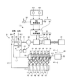
- FIG. 1 is a schematic configuration diagram showing a main machine of the present embodiment.
- FIG. 2 is a schematic diagram showing regions of the engine operation mode and the scavenging supply mode.
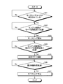
- FIG. 3 is a flowchart showing a control method of the main engine at the time of ship speed increase.
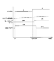
- FIG. 4 is a time chart showing a control method of the main engine at the time of ship speed increase.
- FIG. 5 is a flowchart showing a control method of the main engine at the time of ship deceleration.
- FIG. 6 is a time chart showing a control method of the main engine at the time of ship deceleration.
- FIG. 1 is a schematic configuration diagram showing a main machine of the present embodiment.
- a marine diesel engine (internal combustion engine) 1 as a main engine includes a diesel engine main body 2, an exhaust turbine supercharger 3, an auxiliary blower 4, and a control device 5.
- the diesel engine main body 2 is provided with a plurality of cylinder parts 13, and each cylinder part 13 is supported by a piston so as to be able to reciprocate inside each cylinder part 13. It is connected to the crankshaft via the head.
- the cylinder portion 13 is connected to a scavenging trunk 15 via an intake port 14 and to an exhaust manifold 17 via an exhaust port 16.
- the scavenging trunk 15 is connected to the compressor 21 of the exhaust turbine supercharger 3 via the intake pipe L1.
- the exhaust manifold 17 is connected to the turbine 22 of the exhaust turbine supercharger 3 through an exhaust pipe L2.
- the cylinder portion 13 is provided with an injector (fuel supply device) 18 for injecting fuel (for example, heavy oil, natural gas, etc.).
- Each injector 18 is connected to a fuel pump (not shown).
- the exhaust turbine supercharger 3 is configured such that a compressor 21 and a turbine 22 are coaxially connected via a rotating shaft 23, and the compressor 21 and the turbine 22 can rotate integrally with the rotating shaft 23.
- the compressor 21 is connected to an intake pipe L3 that intakes air from the outside, and is connected to an intake pipe L1 that reaches the scavenging trunk 15.
- the turbine 22 is connected to an exhaust pipe L2 that reaches the exhaust manifold 17 and an exhaust pipe L4 that exhausts to the outside.
- the turbine 22 is driven by the exhaust gas (combustion gas) guided from the exhaust manifold 17 through the exhaust pipe L2, and after driving the compressor 21, the exhaust gas is discharged from the exhaust pipe L4 to the outside.
- the compressor 21 is driven by the turbine 22 and compresses a gas such as air sucked from the intake pipe L3, and then pumps the compressed gas such as air from the intake pipe L1 to the scavenging trunk 15 as a combustion gas.
- the diesel engine main body 2 is provided with a working gas supply device 24 that supplies air (working gas) to the cylinder portion 13 and raises the engine speed by actuating a piston (not shown) of the cylinder portion 13.
- the working gas supply device 24 includes a working gas supply source 25 (for example, an accumulator or a pump), an on-off valve 26, and a working gas supply pipe L5.
- the working gas supply pipe L5 has a proximal end portion to which a working gas supply source 25 is connected, a distal end portion is connected to each cylinder portion 13, and a plurality of on-off valves 26 corresponding to each cylinder portion 13 are provided. Yes.
- the working gas supply device 24 controls the opening and closing of each on-off valve 26 to supply and stop supplying the working gas from the working gas supply source 25 to the cylinder unit 13 from the working gas supply pipe L5. repeat. Thereby, without injecting fuel into the cylinder part 13, the piston (not shown) provided in the cylinder part 13 can be operated and the crankshaft can be rotated via the crosshead.
- the exhaust turbine supercharger 3 is a hybrid supercharger, and is connected to a motor generator 32 via a rotation shaft 31 coaxial with the rotation shaft 23 of the compressor 21 and the turbine 22.
- the motor generator 32 includes a rotor fixed to the rotary shaft 31 and a stator fixed to the casing and disposed around the rotor.
- the motor generator 32 has a power generation function for generating power by being driven by exhaust gas, and also has an electric function for driving and rotating the compressor 21 and the turbine 22.
- the exhaust turbine supercharger 3 includes a power conversion device 33.
- the power conversion device 33 includes a first power conversion unit 34, a power storage unit 35, and a second power conversion unit 36.
- the first power conversion unit 34 is connected to the motor generator 32, and converts AC power generated by the motor generator 32 into DC power and outputs it during the regenerative operation of the motor generator 32.
- the second power conversion unit 36 is connected to the inboard power system 37, and converts the DC power from the first power conversion unit 34 into three-phase AC power suitable for the inboard power system 37 during the regenerative operation of the motor generator 32.
- the power storage unit 35 is connected between the first power conversion unit 34 and the second power conversion unit 36 and stores the DC power from the first power conversion unit 34 by a predetermined amount.
- the power storage unit 35 is provided to smooth the power output to the second power conversion unit 36, and outputs the power stored at the start of the regenerative operation of the motor generator 32 to the second power conversion unit 36.
- the power output to the second power conversion unit 36 after the start of the regenerative operation is output from the motor generator 32 via the first power conversion unit 34.
- the second power conversion unit 36 converts the three-phase AC power from the inboard power system 37 into DC power and outputs it to the first power conversion unit 34 when the motor generator 32 is in a power running operation.
- the first power conversion unit 34 converts the DC power from the second power conversion unit 36 into AC power and outputs the AC power to the motor generator 32 during the power running operation of the motor generator 32.
- the power storage unit 35 stores the DC power from the second power conversion unit 36 by a predetermined amount.
- the power storage unit 35 is provided to smooth the power output to the first power conversion unit 34, and outputs the power stored at the start of the power running operation of the motor generator 32 to the first power conversion unit 34.
- the power output to the first power conversion unit 34 after the power running operation is started is output from the inboard power system 37 via the second power conversion unit 36.
- the configuration of the power conversion device 33 is not described in detail.
- the first power conversion unit 34 is a converter
- the power storage unit 35 is a capacitor
- the second power conversion unit 36 is an inverter.
- the auxiliary blower 4 includes a blower impeller 41 and a blower motor (motor) 42.
- the auxiliary blower 4 is driven when the marine diesel engine 1 is started to compress a gas such as air taken in from the intake pipe L3 via the compressor 21, and then the compressed air or the like is used as a combustion gas. Pressure is fed from the intake pipe L6 to the scavenging trunk 15 via the intake pipe L1.
- the intake pipe L6 is provided in parallel with the intake pipe L1, and the auxiliary blower 4 (blower impeller 41) is provided in the intake pipe L6, the intake pipe L1 and the intake pipe L6 do not need to be provided in parallel. Without providing the pipe L6, only the intake pipe L1 may be provided, and the auxiliary blower 4 may be provided in the intake pipe L1.
- the control device 5 includes a first control device 51 that controls the motor generator 32 and a second control device 52 that controls the diesel engine main body 2 and the auxiliary blower 4.
- the first control device 51 can control the motor generator 32 by controlling the first power converter 34 and the second power converter 36. That is, the first control device 51 controls the functions of the first power conversion unit 34 and the second power conversion unit 36 according to the driving state (regenerative operation state or powering operation state) of the motor generator 32.
- the second control device 52 can drive and control the injector 18 and the working gas supply device 24 in the diesel engine main body 2.
- the second control device 52 controls the fuel injection timing and the fuel injection amount by driving the injectors 18. Further, the second control device 52 controls opening / closing of the on-off valve 26 constituting the working gas supply device 24 to control the working gas supply timing and the working gas supply amount to the cylinder portion 13.
- the second control device 52 can control the scavenging air pressure (intake pressure) by controlling the auxiliary blower 4 to supply a gas such as compressed air to the diesel engine body 2.
- the second control device 52 is connected to a steering handle 53 that navigates the ship.
- the steering handle 53 outputs a main engine speed command to the second control device 52, and the ship can be navigated by controlling the speed of the diesel engine body 2.
- the steering handle 53 can be switched between an in-port navigation mode (rotation speed) as the first engine operation mode and an off-port operation mode as the second engine operation mode.
- the navigation modes in the harbor are further, Full Ahead (full speed at forward speed at harbor speed), Half Ahead (half speed at half speed at harbor speed), Slow Ahead (in harbor) Forward slow speed at high speed), Dead Slow Ahead (Dead Slow Ahead), Dead Slow Astern (Dead Slow Astern), Slow Asturn (Slow Astern: reverse slow speed), half astern (half reverse speed) and full astern (full backward speed).
- Switching between the first engine operation mode and the second engine operation mode is performed by operating the steering handle 5353.
- the control device 5 When the engine start preparation signal 101 is input, the control device 5 starts driving the auxiliary blower 4 to pump a gas such as compressed air to the scavenging trunk 15 of the marine diesel engine 1 as a combustion gas, Increase scavenging air pressure (intake pressure).
- the control device 5 starts driving the working gas supply device 24 to increase the engine rotation speed, and the fuel supply start rotation speed at which the engine rotation speed is set in advance.
- Each injector 18 is driven to supply fuel to the diesel engine body 2. Then, the marine diesel engine 1 starts operation by combustion.
- the control device 5 controls the second power conversion unit 36 to convert the three-phase AC power from the inboard power system 37 into DC power to store the power storage unit 35. And the voltage of the power storage unit 35 reaches a preset standby voltage. Then, when the voltage of the power storage unit 35 reaches the standby voltage and the engine speed reaches the preset mode switching speed, the control device 5 controls the first power conversion unit 34 to control the power storage unit 35.
- the direct current power is converted into alternating current power and the drive of the motor generator 32 is started, while the drive of the auxiliary blower 4 is stopped and the exhaust turbine supercharger 3 is set to the power supply mode.
- control device 5 stops driving assistance by the motor generator 32 and enters the normal operation mode in which the exhaust turbine supercharger 3 is driven by the energy of the exhaust gas, and then the engine load reaches a preset load. Then, the electric power generated by the motor generator 32 by the surplus energy of the exhaust gas is output to the inboard power system 37, and the exhaust turbine supercharger 3 is set to the power generation mode.
- FIG. 2 is a schematic diagram showing regions of the engine operation mode and the scavenging supply mode.
- the control device 5 can switch between the first engine operation mode A and the second engine operation mode B in response to a main engine speed command from the steering handle 53 as shown in FIG. .
- the control device 5 uses the first scavenging supply mode a for driving the auxiliary blower 4, the second scavenging supply mode b for assisting the driving of the exhaust turbine supercharger 3 by the motor generator 32, and the motor generator 32.
- the third scavenging supply mode c in which the driving assistance is stopped and the exhaust turbine supercharger 3 is driven by the exhaust gas energy, and the motor generator 32 is driven by the exhaust gas surplus energy while driving the exhaust turbine supercharger 3 by the exhaust gas energy.
- a fourth scavenging supply mode d for supplying the power generated by the engine to the inboard power system 37, and the rotational speed of the diesel engine main body 2 (the load of the main engine main body) varies from the low engine speed range to the high engine speed range.
- the third scavenging supply mode is changed from the first scavenging supply mode a to the second scavenging supply mode b, and from the second scavenging supply mode b to the third scavenging supply mode c.
- From c to the fourth scavenging supply mode d can switch the scavenge supply mode.
- the switching between the first scavenging supply mode a and the second scavenging supply mode b is performed at a preset mode switching speed (main engine specified load), and the second scavenging supply mode b and the third scavenging supply mode.
- Switching to c and switching between the third scavenging supply mode c and the fourth scavenging supply mode d are executed by a preset mode switching load (mode switching output or main engine prescribed load).
- the driving of the exhaust turbine supercharger 3 by the motor generator 32 is started, the driving of the auxiliary blower 4 is stopped, and the mode is switched to the second scavenging supply mode b.
- the driving assistance of the exhaust turbine supercharger 3 by the motor generator 32 is started, and the driving assistance of the exhaust turbine supercharger 3 is started.
- the driving of the auxiliary blower 4 is stopped.
- the auxiliary blower 4 is started, the driving of the exhaust turbine supercharger 3 by the motor generator 32 is stopped, and the mode is switched to the first scavenging supply mode a.
- the rotational speed of the diesel engine main body 2 reaches the second mode switching rotational speed
- the driving of the auxiliary blower 4 is started, and after the second standby time set in advance from the start of driving of the auxiliary blower 4,
- the drive of the exhaust turbine supercharger 3 by the generator 32 is stopped.
- the second mode switching speed is set to a value lower than the first mode switching speed.
- switching between the second scavenging supply mode b and the third scavenging supply mode c and switching between the third scavenging supply mode c and the fourth scavenging supply mode d are mode switching in which the load of the diesel engine body 2 is set in advance. It is executed by reaching the load (mode switching output).
- the switching between the first scavenging supply mode “a” and the second scavenging supply mode “b” is performed according to the preset first mode switching rotational speed and second mode switching rotational speed, but with the load of the marine diesel engine 1.
- the load of the marine diesel engine 1 includes the load (output) of the diesel engine body 2, the scavenging air pressure, the fuel injection amount, and the like in addition to the engine speed.
- the first mode switching speed and the second mode switching speed are set to a higher speed than the mode switching speed at which switching between the first engine operation mode a and the second engine operation mode b is performed.
- the engine speed is increased and the engine output is increased to switch from the harbor navigation mode to the port navigation mode.
- the engine output fluctuates in accordance with the operational state of the ship (for example, wind direction, wave height, etc.), and therefore the engine output fluctuates up and down without matching the engine speed.
- the first scavenging supply mode a and the second scavenging supply mode b are switched by the engine output of the diesel engine main body 2, even if the engine speed fluctuates even if the rotation speed is constant, the first scavenging supply mode There is a possibility that switching between a and the second scavenging supply mode b is frequently performed. Then, the start and stop of driving assistance of the exhaust turbine supercharger 3 and the start and stop of driving of the auxiliary blower 4 are repeated.
- FIG. 3 is a flowchart showing a control method of the main engine at the time of ship acceleration (for example, at the time of departure of the ship)
- FIG. 4 is a time chart showing a control method of the main engine at the time of ship acceleration
- FIG. 6 is a time chart showing a control method of the main engine when the ship decelerates.
- the main engine control method of the present embodiment includes a step of driving the auxiliary blower 4 to supply air to the diesel engine main body 2 during operation in the first scavenging supply mode a, and a rotational speed of the diesel engine main body 2 is increased.
- the main engine control method of the present embodiment is preset by a step of driving the exhaust turbine supercharger 3 by the motor generator 32 during operation in the second scavenging supply mode b, and a reduction in the rotational speed of the diesel engine body 2. And starting the driving of the auxiliary blower 4 when the second mode switching rotational speed is reached, and stopping the driving of the exhaust turbine supercharger 3 by the motor generator 32.
- step S ⁇ b> 1 the control device 5 operates the auxiliary blower 4 when the engine start preparation signal 101 is input. Then, the combustion gas is pumped to the cylinder portion 13 through the scavenging trunk 15 to increase the scavenging pressure (intake pressure). In step S2, the diesel engine body 2 is activated.
- the control device 5 controls the second power conversion unit 36 to convert the three-phase AC power from the inboard power system 37 into DC power, start storing power in the power storage unit 35, and maintain the standby voltage. .
- the control device 5 controls the opening and closing of the on-off valve 26 to supply the working gas to the diesel engine main body 2, thereby executing an air run and increasing the engine speed.
- the control device 5 drives the injector 18 and injects fuel into the cylinder portion 13 of the diesel engine body 2. Then, the marine diesel engine 1 starts combustion by igniting the fuel in the cylinder portion 13 and starting combustion.
- step S3 the control device 5 determines whether or not the motoring mode is selected.
- the motoring mode is a mode in which in the exhaust turbine supercharger 3, the motor generator 32 is controlled by the power converter 33, thereby supplying power to the motor generator 32 and generating power by the motor generator 32. It is.
- the process waits as it is. If it is determined that the motoring mode is selected (Yes), the process proceeds to step S4.
- step S4 the control device 5 determines whether or not the engine speed has reached the first mode switching speed.
- the process waits as it is, and it is determined that the engine speed has reached the first mode switching speed (Yes). Then, the process proceeds to step S5.
- step S5 the control device 5 starts motoring. That is, the control device 5 controls the first power conversion unit 34 to convert the DC power of the power storage unit 35 into AC power and start driving the motor generator 32, and use the power from the inboard power system 37. It outputs to the motor generator 32 and motoring is started.
- step S6 the control device 5 determines whether or not the first waiting time has elapsed since the start of motoring. If it is determined that the first standby time has not elapsed (No), the process waits as it is. If it is determined that the first standby time has elapsed (Yes), the driving of the auxiliary blower 4 is stopped in step S7. To do. Thereafter, in step S8, the control device 5 determines whether or not the engine load has reached the mode switching load. Here, if it is determined that the engine load has not reached the mode switching load (No), the process waits as it is. If it is determined that the engine load has reached the mode switching load (Yes), the process proceeds to step S9.
- step S9 the control device 5 stops motoring. That is, the control device 5 controls the first power conversion unit 34 to stop the power supply from the inboard power system 37 to the motor generator 32 and stop the motoring. After that, after setting the normal operation mode in which the exhaust turbine supercharger 3 is driven by the energy of the exhaust gas, when the engine load reaches a preset load, power generation of the motor generator 32 is started by the surplus energy of the exhaust gas. The electric power is output to the inboard power system 37.
- step S21 determines whether or not the motoring mode is selected.
- the process stands by, and if it is determined that the motoring mode is selected (Yes), the process proceeds to step S22.
- step S22 control device 5 determines whether or not the engine load has reached the mode switching load. If it is determined that the engine load has not reached the mode switching load (No), the process waits as it is. If it is determined that the engine load has reached the mode switching load (Yes), the process proceeds to step S23.
- step S23 the control device 5 starts motoring. That is, the control device 5 controls the first power conversion unit 34 to convert the DC power of the power storage unit 35 into AC power and start driving the motor generator 32, and use the power from the inboard power system 37. It outputs to the motor generator 32 and motoring is started.
- step S24 control device 5 determines whether or not the engine speed has decreased and has reached the second mode switching speed. If it is determined that the engine speed has not reached the second mode switching speed (No), the process waits as it is, and it is determined that the engine speed has reached the second mode switching speed (Yes). Then, the process proceeds to step S25.
- step S25 the control device 5 operates the auxiliary blower 4 to pump the combustion gas to the cylinder portion 13 via the scavenging trunk 15.
- step S ⁇ b> 26 the control device 5 determines whether or not the second standby time has elapsed since the operation of the auxiliary blower 4. Here, if it is determined that the second standby time has not elapsed (No), the process waits as it is, and if it is determined that the second standby time has elapsed (Yes), the process proceeds to step S27.
- step S27 the control device 5 stops the motoring. That is, the control device 5 controls the first power conversion unit 34 to stop the power supply from the inboard power system 37 to the motor generator 32 and stop the motoring.
- the diesel engine main body 2 the exhaust turbine supercharger 3 including the compressor 21 and the turbine 22, and the motor generator 32 that drives the exhaust turbine supercharger 3.
- an auxiliary blower 4 for supplying air to the diesel engine body 2, the exhaust gas turbocharger 3 is driven by the first scavenging supply mode a for driving the auxiliary blower 4 and the motor generator 32.
- the second scavenging supply mode b is provided, and the first scavenging supply mode a and the second scavenging supply mode b are switched at a preset mode switching speed (main engine specified load).
- the diesel engine can be switched by switching between the first scavenging supply mode a for driving the auxiliary blower 4 and the second scavenging supply mode b for driving the exhaust turbine supercharger 3 by the motor generator 32 in an auxiliary manner.
- the exhaust turbine supercharger 3 can be driven stably during low load operation where the rotation speed of the main body 2 is frequently changed, and the auxiliary blower 4 is driven only at an appropriate time to ensure an energy saving effect.
- the efficiency of the marine diesel engine 1 during low-load operation can be improved.
- the motor generator 32 when the rotation speed of the diesel engine main body 2 rises and reaches a preset first main engine specified rotation speed during operation in the first scavenging supply mode a, the motor generator 32 is reached. The driving of the exhaust turbine supercharger 3 is started and the driving of the auxiliary blower 4 is stopped. Therefore, by switching from the first scavenging supply mode a to the second scavenging supply mode b in accordance with the rotational speed of the diesel engine main body 2, the exhaust turbine supercharger 3 can be properly activated.
- the driving of the auxiliary blower 4 is stopped after the elapse of a first standby time set in advance from the start of driving of the exhaust turbine supercharger 3. Therefore, by starting the driving assistance of the exhaust turbine supercharger 3 by the motor generator 32 and stopping the driving of the auxiliary blower 4 after the elapse of the first waiting time, the motor generator only during the first waiting time. 32, the exhaust turbine supercharger 3 is driven and assisted, and air is supplied to the diesel engine body 2 by the auxiliary blower 4, so that the diesel engine body 2 can be operated stably.
- the auxiliary blower 4 When the rotational speed of the diesel engine body 2 decreases and reaches a preset second main engine specified rotational speed during operation in the second scavenging supply mode b, the auxiliary blower 4 The driving is started and the driving of the exhaust turbine supercharger 3 by the motor generator 32 is stopped. Therefore, the exhaust turbine supercharger 3 can be stopped appropriately by switching from the second scavenging supply mode b to the first scavenging supply mode a in accordance with the rotational speed of the diesel engine body 2.
- the driving of the exhaust turbine supercharger 3 by the motor generator 32 is stopped after elapse of a second standby time set in advance from the start of driving of the auxiliary blower 4. Therefore, by stopping the driving assistance of the exhaust turbine supercharger 3 by the motor generator 32 after the second standby time has elapsed from the start of driving of the auxiliary blower 4, the diesel engine is operated by the auxiliary blower 4 only during the second standby time. While supplying air to the main body 2 and driving assisting the exhaust turbine supercharger 3 by the motor generator 32, the diesel engine main body 2 can be stably operated.
- the first scavenging supply mode a and the second scavenging supply mode b are switched according to the specified rotational speed of the diesel engine body 2. Therefore, at the time of this switching, the start and stop of driving assistance of the exhaust turbine supercharger 3 and the start and stop of driving of the auxiliary blower 4 are not repeatedly performed, and driving assistance of the exhaust turbine supercharger 3 is stably performed. It can be started and stopped, and the reliability of various devices can be improved.
- control handle 5 is provided with a control handle 53 that outputs a command for the number of times of the main engine, and with respect to the switching speed between the navigation mode in the port and the operation mode outside the port by the control handle 53.
- the specified rotational speed of the diesel engine body 2 is set high. Therefore, the driving assistance of the exhaust turbine supercharger 3 can be started and stopped stably.
- the step of supplying the combustion gas to the diesel engine main body 2 by driving the auxiliary blower 4 and the rotational speed of the diesel engine main body 2 are increased and preset. And the step of starting driving the exhaust turbine supercharger 3 by the motor generator 32 and stopping the driving of the auxiliary blower 4 when the first main engine prescribed load is reached. Therefore, the exhaust turbine supercharger 3 can be driven stably, and the auxiliary blower 4 can be driven limitedly at an appropriate time to ensure an energy saving effect.
- Efficiency can be improved.
- the step of driving the exhaust turbine supercharger 3 by the motor generator 32 in the high rotation region of the diesel engine body 2 and the rotational speed of the diesel engine body 2 are reduced. Then, when reaching the preset second main engine prescribed rotational speed, the driving of the auxiliary blower 4 is started and the driving of the exhaust turbine supercharger 3 by the motor generator 32 is stopped. Accordingly, the exhaust turbine supercharger 3 can be stably stopped, and the auxiliary blower 4 can be driven limitedly at an appropriate time to ensure an energy saving effect.
- Efficiency can be improved.
- the main engine of the present embodiment includes the diesel engine main body 2, the exhaust turbine supercharger 3, the motor generator 32, the auxiliary blower 4, and the control device 5. Therefore, the exhaust turbine supercharger 3 can be driven stably during the low load operation of the diesel engine main body 2, and the auxiliary blower 4 can be driven limitedly at an appropriate time to ensure an energy saving effect. The efficiency of the marine diesel engine 1 during low load operation can be improved.
- the marine vessel of this embodiment includes a marine diesel engine 1. Therefore, the efficiency at the time of low load operation of the diesel engine main body 2 can be improved, and energy saving at the time of navigation can be realized.
Landscapes
- Engineering & Computer Science (AREA)
- Chemical & Material Sciences (AREA)
- Combustion & Propulsion (AREA)
- Mechanical Engineering (AREA)
- General Engineering & Computer Science (AREA)
- Supercharger (AREA)
- Output Control And Ontrol Of Special Type Engine (AREA)
Abstract
主機の制御装置及び方法、主機、船舶において、ディーゼルエンジン本体(2)と、コンプレッサ(21)及びタービン(22)を備える排気タービン過給機(3)と、排気タービン過給機(3)を駆動する電動発電機(32)と、ディーゼルエンジン本体(2)に空気を供給する補助ブロワ(4)とを備える舶用ディーゼルエンジン(1)において、ディーゼルエンジン本体(2)の低回転領域で補助ブロワ(4)を駆動する第1掃気供給モード(a)と、ディーゼルエンジン本体(2)の高回転領域で電動発電機(32)により排気タービン過給機(3)を駆動する第2掃気供給モード(b)とを設け、第1掃気供給モード(a)と第2掃気供給モード(b)を予め設定されたモード切替回転数(主機規定負荷)により切替えることで、主機の低負荷運転時の効率を向上する。
Description
本発明は、過給機を備える主機の制御装置及び方法、主機の制御装置を備える主機、主機を備える船舶に関するものである。
例えば、船舶に搭載される主機としての内燃機関は、燃費向上や排ガス中のCO2を削減するために過給機が装着されている。この過給機は、内燃機関から排出される排ガスを利用してタービン及びコンプレッサを駆動することにより、内燃機関に吸気を圧縮供給して内燃機関の出力を向上させるものである。また、過給機のコンプレッサを駆動した余剰のエネルギを用いて発電機で発電を行うターボチャージャ発電装置がある。このターボチャージャ発電装置は、過給機に発電機を直結し、余剰の排ガスエネルギを電気エネルギとして回収することで、船内における他の発電機の発電量を削減するものである。
このようなターボチャージャ発電装置としては、下記特許文献1及び非特許文献1に記載されたものがある。
三菱重工技報 Vol.49 No.1(2012)新製品・新技術特集「排ガスで発電する大型舶用ハイブリッド過給機の実用化」
上述した非特許文献1に記載では、内燃機関の起動時や低負荷運転時には過給機だけでは十分な燃焼用気体を内燃機関に供給できないため、補助ブロワを用いて内燃機関に供給する吸気を確保している。しかし、補助ブロワは、電動機により一定の速度で運転して一定量の空気を内燃機関に供給するものであることから、制御の自由度が低く、最適な運転が困難で、効率が悪いという問題がある。
本発明は、上述した課題を解決するものであり、主機の低負荷運転時の効率を向上する主機の制御装置及び方法、主機、船舶を提供することを目的とする。
上記の目的を達成するための本発明の主機の制御装置は、主機本体と、コンプレッサ及びタービンを備える過給機と、前記過給機を駆動する電動機と、前記主機本体に空気を供給する補助ブロワとを備える主機において、前記補助ブロワを駆動する第1掃気供給モードと、前記電動機により前記過給機を駆動する第2掃気供給モードとが設けられ、前記第1掃気供給モードと前記第2掃気供給モードを予め設定された主機規定負荷により切替える、ことを特徴とするものである。
従って、補助ブロワを駆動して主機本体に空気を供給する第1掃気供給モードと、電動機により過給機を補助的に駆動する第2掃気供給モードとを主機規定負荷により切替えることで、主機本体の回転数変更頻度の多い低負荷運転時に、過給機を安定して駆動することができると共に、補助ブロワを適正時期だけ限定的に駆動して省エネ効果を確保することができ、主機の低負荷運転時の効率を向上することができる。
本発明の主機の制御装置では、前記第1掃気供給モードでの運転時に、前記主機本体の負荷が上昇して予め設定された第1主機規定負荷に到達すると、前記電動機による前記過給機の駆動を開始して前記補助ブロワの駆動を停止することを特徴としている。
従って、主機本体の負荷に応じて第1掃気供給モードから第2掃気供給モードに切替えることで、過給機を適正に起動することができる。
本発明の主機の制御装置では、前記過給機の駆動開始から予め設定された第1待機時間の経過後、前記補助ブロワの駆動を停止することを特徴としている。
従って、電動機による過給機の駆動補助を開始して第1待機時間の経過後に補助ブロワの駆動を停止することで、第1待機時間の間だけ、電動機により過給機を駆動補助すると共に、補助ブロワにより主機本体に空気を供給することとなり、主機を安定して運転することができる。
本発明の主機の制御装置では、前記第2掃気供給モードでの運転時に、前記主機本体の負荷が低下して予め設定された第2主機規定負荷に到達すると、前記補助ブロワの駆動を開始して前記電動機による前記過給機の駆動を停止することを特徴としている。
従って、主機本体の負荷に応じて第2掃気供給モードから第1掃気供給モードに切替えることで、過給機を適正に停止することができる。
本発明の主機の制御装置では、前記補助ブロワの駆動開始から予め設定された第2待機時間の経過後、前記電動機による前記過給機の駆動を停止することを特徴としている。
従って、補助ブロワの駆動開始から第2待機時間の経過後に電動機による過給機の駆動補助を停止することで、第2待機時間の間だけ、補助ブロワにより主機本体に空気を供給すると共に、電動機により過給機を駆動補助することとなり、主機を安定して雨天することができる。
本発明の主機の制御装置では、前記主機本体の負荷は、主機回転数であり、前記主機規定負荷は、予め設定された主機規定回転数であることを特徴としている。
従って、第1掃気供給モードと第2掃気供給モードとを主機規定回転数により切替えることで、この切替時に、過給機の駆動補助の開始及び補助停止と補助ブロワの駆動の開始及び停止が繰り返し行われることはなく、過給機の駆動補助を安定して開始及び停止することができ、機器の信頼性を確保することができる。
本発明の主機の制御装置では、前記制御装置に主機回数数指令を出力する操縦ハンドルが設けられ、前記操縦ハンドルによる港湾内高校モードと港湾外運航モードの切替回転数に対して、前記主機規定回転数が高く設定されることを特徴としている。
従って、過給機の駆動補助を安定して開始及び停止することができる。
また、本発明の主機の制御方法は、補助ブロワを駆動して前記主機本体に燃焼用気体を供給する工程と、主機本体の負荷が上昇して予め設定された第1主機規定負荷に到達すると電動機による過給機の駆動を開始して前記補助ブロワの駆動を停止する工程と、を備えることを特徴とするものである。
従って、過給機を安定して起動することができると共に、補助ブロワを適正時期だけ限定的に駆動して省エネ効果を確保することができ、主機の低負荷運転時の効率を向上することができる。
また、本発明の主機の制御方法は、主機本体の高回転領域で電動機により過給機を駆動する工程と、前記主機本体の負荷が低下して予め設定された第2主機規定負荷に到達すると補助ブロワの駆動を開始して前記電動機による過給機の駆動を停止する工程と、を備えることを特徴とするものである。
従って、過給機を安定して停止することができると共に、補助ブロワを適正時期だけ限定的に駆動して省エネ効果を確保することができ、主機の低負荷運転時の効率を向上することができる。
また、本発明の主機は、主機本体と、コンプレッサ及びタービンを備える過給機と、前記過給機を駆動する電動機と、前記主機本体に空気を供給する補助ブロワと、前記補助ブロワを駆動する第1掃気供給モードと前記電動機により前記過給機を駆動する第2掃気供給モードとを予め設定された主機規定負荷により切替える制御装置と、を備えることを特徴とするものである。
従って、補助ブロワを駆動して主機本体に空気を供給する第1掃気供給モードと、電動機により過給機を駆動する第2掃気供給モードとを主機規定負荷により切替えることで、主機本体の低負荷運転時に、過給機を安定して駆動することができると共に、補助ブロワを適正時期だけ限定的に駆動して省エネ効果を確保することができ、主機の低負荷運転時の効率を向上することができる。
また、本発明の船舶は、前記主機を備えることを特徴とするものである。
従って、主機の低負荷運転時の効率を向上することができ、航行時の省エネを実現することができる。
本発明の主機の制御装置及び方法、主機、船舶によれば、主機の低負荷運転時の効率を向上することができる。
以下に添付図面を参照して、本発明に係る主機の制御装置及び方法、主機、船舶の好適な実施形態を詳細に説明する。なお、この実施形態により本発明が限定されるものではなく、また、実施形態が複数ある場合には、各実施形態を組み合わせて構成するものも含むものである。
図1は、本実施形態の主機を表す概略構成図である。
本実施形態にて、図1に示すように、主機としての舶用ディーゼルエンジン(内燃機関)1は、ディーゼルエンジン本体2と、排気タービン過給機3と、補助ブロワ4と、制御装置5とを備えている。ディーゼルエンジン本体2は、複数のシリンダ部13が設けられており、各々の各シリンダ部13は、図示しないが、内部にピストンがそれぞれ往復移動自在に支持されており、各ピストンは、下部がクロスヘッドを介してクランク軸に連結されている。
シリンダ部13は、吸気ポート14を介して掃気トランク15が連結されると共に、排気ポート16を介して排気マニホールド17が連結されている。そして、掃気トランク15は、吸気管L1を介して排気タービン過給機3のコンプレッサ21に連結されている。また、排気マニホールド17は、排気管L2を介して排気タービン過給機3のタービン22に連結されている。また、シリンダ部13は、内部に燃料(例えば、重油、天然ガスなど)を噴射するインジェクタ(燃料供給装置)18がそれぞれ設けられている。各インジェクタ18は、図示しない燃料ポンプが連結されている。
排気タービン過給機3は、コンプレッサ21とタービン22が回転軸23を介して同軸上に連結されて構成されており、コンプレッサ21とタービン22は、回転軸23により一体回転することができる。コンプレッサ21は、外部から吸気する吸気管L3が連結されると共に、掃気トランク15に至る吸気管L1が連結されている。タービン22は、排気マニホールド17に至る排気管L2が連結されると共に、外部に排気する排気管L4が連結されている。
そのため、タービン22は、排気マニホールド17から排気管L2を通して導かれた排ガス(燃焼ガス)によって駆動し、コンプレッサ21を駆動した後、排ガスを排気管L4から外部に排出する。一方、コンプレッサ21は、タービン22により駆動し、吸気管L3から吸気した空気等の気体を圧縮した後、圧縮した空気などの気体を燃焼用気体として吸気管L1から掃気トランク15に圧送する。
また、ディーゼルエンジン本体2は、シリンダ部13に空気(作動気体)を供給し、シリンダ部13の図示しないピストンを作動させることでエンジン回転数を上昇させる作動気体供給装置24が設けられている。この作動気体供給装置24は、作動気体供給源25(例えば、アキュムレータやポンプなど)と、開閉弁26と、作動気体供給管L5を備えている。作動気体供給管L5は、基端部に作動気体供給源25が連結され、先端部が各々のシリンダ部13に連結されるとともに、各々のシリンダ部13に対応する開閉弁26が複数設けられている。作動気体供給装置24は、舶用ディーゼルエンジン1の起動時に、各々の開閉弁26を開閉制御することで、作動気体供給源25の作動気体を作動気体供給管L5からシリンダ部13に供給・供給停止を繰り返す。これにより、シリンダ部13の内部に燃料を噴射することなく、シリンダ部13に設けられた図示しないピストンを作動させ、クロスヘッドを介してクランク軸を回転させることができる。
排気タービン過給機3は、ハイブリッド過給機であって、コンプレッサ21及びタービン22の回転軸23と同軸上の回転軸31を介して電動発電機32が連結されている。電動発電機32は、図示しないが、回転軸31に固定されるロータと、ケーシングに固定されてロータの周囲に配置されるステータにより構成される。この電動発電機32は、排ガスにより駆動されることで発電する発電機能を有すると共に、コンプレッサ21及びタービン22を駆動回転する電動機能を有している。
排気タービン過給機3は、電力変換装置33を備えている。電力変換装置33は、第1電力変換部34と、蓄電部35と、第2電力変換部36とを備えている。第1電力変換部34は、電動発電機32に接続され、電動発電機32の回生動作時に、電動発電機32が発電した交流電力を直流電力に変換して出力する。第2電力変換部36は、船内電力系統37に接続され、電動発電機32の回生動作時に、第1電力変換部34からの直流電力を船内電力系統37に適した三相交流電力に変換して船内電力系統37に出力する。蓄電部35は、第1電力変換部34と第2電力変換部36との間に接続され、第1電力変換部34からの直流電力を所定量だけ蓄電する。蓄電部35は、第2電力変換部36に出力される電力を平滑化するために設けられ、電動発電機32の回生動作開始時に蓄電した電力を第2電力変換部36に出力する。回生動作開始後に第2電力変換部36に出力される電力は、第1電力変換部34を介して電動発電機32から出力される。
また、第2電力変換部36は、電動発電機32の力行動作時に、船内電力系統37からの三相交流電力を直流電力に変換して第1電力変換部34に出力する。第1電力変換部34は、電動発電機32の力行動作時に、第2電力変換部36からの直流電力を交流電力に変換して電動発電機32に出力する。蓄電部35は、第2電力変換部36からの直流電力を所定量だけ蓄電する。蓄電部35は、第1電力変換部34に出力される電力を平滑化するために設けられ、電動発電機32の力行動作開始時に蓄電した電力を第1電力変換部34に出力する。力行動作開始後に第1電力変換部34に出力される電力は、第2電力変換部36を介して船内電力系統37から出力される。
ここで、電力変換装置33の構成は、詳細に説明しないが、例えば、第1電力変換部34は、コンバータ、蓄電部35は、コンデンサ、第2電力変換部36は、インバータである。
補助ブロワ4は、ブロワ用インペラ41とブロワ用電動機(モータ)42とから構成される。補助ブロワ4は、舶用ディーゼルエンジン1の起動時に駆動されることで、吸気管L3からコンプレッサ21を経由して吸気した空気等の気体を圧縮した後、圧縮した空気等の気体を燃焼用気体 として吸気管L6から吸気管L1を経由した掃気トランク15に圧送する。なお、吸気管L1と並列に吸気管L6を設け、この吸気管L6に補助ブロワ4(ブロワ用インペラ41)を設けたが、吸気管L1と吸気管L6は、並列に設ける必要はなく、吸気管L6を設けることなく、吸気管L1のみを設け、吸気管L1に補助ブロワ4を設けてもよい。
制御装置5は、電動発電機32を制御する第1制御装置51と、ディーゼルエンジン本体2及び補助ブロワ4を制御する第2制御装置52とを備えている。
第1制御装置51は、第1電力変換部34と第2電力変換部36を制御することで、電動発電機32を制御することができる。即ち、第1制御装置51は、電動発電機32の駆動状態(回生動作状態、または、力行動作状態)に応じて第1電力変換部34と第2電力変換部36の機能を制御する。
第2制御装置52は、ディーゼルエンジン本体2におけるインジェクタ18と作動気体供給装置24を駆動制御することができる。また、第2制御装置52は、各インジェクタ18を駆動制御して燃料噴射時期や燃料噴射量を制御する。更に、第2制御装置52は、作動気体供給装置24を構成する開閉弁26を開閉制御してシリンダ部13への作動気体供給時期や作動気体供給量を制御する。また、第2制御装置52は、補助ブロワ4を駆動制御することで、ディーゼルエンジン本体2への圧縮した空気等の気体の供給し、掃気圧(吸気圧)を制御することができる。
また、第2制御装置52は、船舶を航行する操縦ハンドル53が接続されている。この操縦ハンドル53は、第2制御装置52に対して主機回転数指令を出力するものであり、ディーゼルエンジン本体2の回転数を制御することで船舶を航行させることができる。操縦ハンドル53は、第1エンジン運転モードとしての港湾内航行モード(回転数)と、第2エンジン運転モードとしての港湾外運航モードに切り替えることができる。
港湾内航行モードは、さらにフル・アヘッド(Full Ahead:港内速力での前進全速回転数)、ハーフ・アヘッド(Half Ahead:港内速力での前進半速回転数)、スロー・アヘッド(Slow Ahead:港内速力での前進微速回転数)、デッド・スロー・アヘッド(Dead Slow Ahead:港内速力での前進最微速回転数)、デッド・スロー・アスターン(Dead Slow Astern:後進最微速回転数)、スロー・アスターン(Slow Astern:後進微速回転数)、ハーフ・アスターン(Half Astern:後進半速回転数)およびフル・アスターン(Full Astern:後進全速回転数)に切り替えることができる。この第1エンジン運転モードと第2エンジン運転モードとの切替は、操縦ハンドル5353の操作により実施される。
制御装置5は、エンジン起動準備信号101が入力されると、補助ブロワ4の駆動を開始することで、圧縮した空気等の気体を燃焼用気体として舶用ディーゼルエンジン1の掃気トランク15に圧送し、掃気圧(吸気圧)を上昇させる。制御装置5は、エンジン回転起動開始信号102が入力されると、作動気体供給装置24の駆動を開始することで、エンジン回転数を上昇させ、エンジン回転数が予め設定された燃料供給開始回転数に到達すると、各インジェクタ18を駆動してディーゼルエンジン本体2に燃料を供給する。すると、舶用ディーゼルエンジン1が燃焼による運転を開始する。
また、制御装置5は、エンジン起動準備信号101が入力されると、第2電力変換部36を制御することで、船内電力系統37からの三相交流電力を直流電力に変換して蓄電部35に蓄電し、蓄電部35の電圧を予め設定された待機電圧に到達させる。そして、制御装置5は、蓄電部35の電圧が待機電圧に到達し、エンジン回転数が予め設定されたモード切替回転数に到達すると、第1電力変換部34を制御することで、蓄電部35の直流電力を交流電力に変換して電動発電機32の駆動を開始する一方、補助ブロワ4の駆動を停止し、排気タービン過給機3を給電モードとする。その後、制御装置5は、電動発電機32による駆動補助を停止して、排ガスのエネルギによって排気タービン過給機3を駆動する通常運転モードとしたのち、エンジン負荷が予め設定された負荷に到達すると、排ガスの余剰エネルギによって電動発電機32が発生した電力を船内電力系統37に出力し、排気タービン過給機3を発電モードとする。
図2は、エンジン運転モードと掃気供給モードの領域を表す概略図である。本実施形態にて、制御装置5は、図2に示すように、操縦ハンドル53からの主機回転数指令を受けて、第1エンジン運転モードAと、第2エンジン運転モードBに切り替えることができる。このとき、制御装置5は、補助ブロワ4を駆動する第1掃気供給モードaと、電動発電機32により排気タービン過給機3を駆動補助する第2掃気供給モードbと、電動発電機32による駆動補助を停止して排ガスのエネルギによって排気タービン過給機3を駆動する第3掃気供給モードcと、排ガスのエネルギによって排気タービン過給機3を駆動すると共に排ガスの余剰エネルギによって電動発電機32が発電した電力を船内電力系統37に供給する第4掃気供給モードdとを備えており、ディーゼルエンジン本体2の回転数(主機本体の負荷)がエンジン低回転領域からエンジン高回転領域に変動するに従い、第1掃気供給モードaから第2掃気供給モードbへ、第2掃気供給モードbから第3掃気供給モードcへ、第3掃気供給モードcから第4掃気供給モードdへ掃気供給モードを切り替えることができる。ここで、第1掃気供給モードaと第2掃気供給モードbとの切替は、予め設定されたモード切替回転数(主機規定負荷)により実行し、第2掃気供給モードbと第3掃気供給モードcとの切替及び第3掃気供給モードcと第4掃気供給モードdとの切替は、予め設定されたモード切替負荷(モード切替出力または主機規定負荷)により実行する。
具体的に、第1掃気供給モードaでの運転時に、ディーゼルエンジン本体2の回転数(負荷)が上昇して予め設定された第1モード切替回転数(第1主機規定負荷)に到達すると、電動発電機機32による排気タービン過給機3の駆動を開始して補助ブロワ4の駆動を停止して第2掃気供給モードbに切替える。このとき、ディーゼルエンジン本体2の回転数が第1モード切替回転数に到達すると、電動発電機32による排気タービン過給機3の駆動補助を開始し、排気タービン過給機3の駆動補助開始から予め設定された第1待機時間の経過後、補助ブロワ4の駆動を停止する。
また、第2掃気供給モードbでの運転時に、ディーゼルエンジン本体2の回転数(負荷)が低下して予め設定された第2モード切替回転数(第2主機規定負荷)に到達すると、補助ブロワ4の駆動を開始して電動発電機32による排気タービン過給機3の駆動を停止して第1掃気供給モードaに切替える。このとき、ディーゼルエンジン本体2の回転数が第2モード切替回転数に到達すると、補助ブロワ4の駆動を開始し、補助ブロワ4の駆動開始から予め設定された第2待機時間の経過後、電動発電機32による排気タービン過給機3の駆動を停止する。この場合、第2モード切替回転数は、第1モード切替回転数より低い値に設定されている。
更に、第2掃気供給モードbと第3掃気供給モードcとの切替及び第3掃気供給モードcと第4掃気供給モードdとの切替は、ディーゼルエンジン本体2の負荷が予め設定されたモード切替回負荷(モード切替出力)に到達することで実行する。
ここで、第1掃気供給モードaと第2掃気供給モードbとの切替は、予め設定された第1モード切替回転数と第2モード切替回転数により実行したが、舶用ディーゼルエンジン1の負荷であればよい。即ち、舶用ディーゼルエンジン1の負荷とは、エンジン回転数の他に、ディーゼルエンジン本体2の負荷(出力)や掃気圧や燃料噴射量などがある。また、第1モード切替回転数と第2モード切替回転数は、第1エンジン運転モードaと第2エンジン運転モードbとの切替を実行するモード切替回転数より高い回転数に設定される。
ここで、第1掃気供給モードaと第2掃気供給モードbとは、ディーゼルエンジン本体2の回転数により切替えることが望ましい。操縦ハンドル53が操作されると、エンジン回転数が上昇すると共にエンジン出力が上昇し、港湾内航行モードから港湾外運航モードに切り替わる。このとき、エンジン出力は、船舶の運航状態(例えば、風向き、波の高さなど)に応じて変動するため、回転数に対してエンジン出力が一致せずに上下に変動する。そのため、例えば、第1掃気供給モードaと第2掃気供給モードbとをディーゼルエンジン本体2のエンジン出力により切替えると、回転数が一定であっても、エンジン出力が変動すると、第1掃気供給モードaと第2掃気供給モードbとの切替えが頻繁に行われるおそれがある。すると、排気タービン過給機3の駆動補助の開始と補助停止、補助ブロワ4の駆動開始と停止が繰り返し行われる。一方、第1掃気供給モードaと第2掃気供給モードbとをディーゼルエンジン本体2の回転数により切替えると、第1掃気供給モードaと第2掃気供給モードbとの切替えが頻繁に行われることはなく、排気タービン過給機3の駆動補助の開始と補助停止、補助ブロワ4の駆動開始と停止が繰り返し行われることはない。
ここで、本実施形態の主機の制御装置を用いた制御方法について、フローチャートとタイムチャートを用いて詳細に説明する。図3は、船舶増速時(例えば、船舶の出航時)における主機の制御方法を表すフローチャート、図4は、船舶増速時における主機の制御方法を表すタイムチャート、図5は、船舶減速時(例えば、船舶出港時)における主機の制御方法を表すフローチャート、図6は、船舶減速時における主機の制御方法を表すタイムチャートである。
本実施形態の主機の制御方法は、第1掃気供給モードaでの運転時に補助ブロワ4を駆動してディーゼルエンジン本体2に空気を供給する工程と、ディーゼルエンジン本体2の回転数が上昇して第1モード切替回転数に到達すると電動発電機32による排気タービン過給機3の駆動を開始して補助ブロワ4の駆動を停止する工程とを備える。
本実施形態の主機の制御方法は、第2掃気供給モードbでの運転時に電動発電機32により排気タービン過給機3を駆動する工程と、ディーゼルエンジン本体2の回転数が低下して予め設定された第2モード切替回転数に到達すると補助ブロワ4の駆動を開始して電動発電機32による排気タービン過給機3の駆動を停止する工程とを備える。
本実施形態の主機の制御方法において、船舶の増速時、図3に示すように、ステップS1にて、制御装置5は、エンジン起動準備信号101が入力されると、補助ブロワ4を作動して掃気トランク15を介してシリンダ部13に燃焼用気体を圧送し、掃気圧(吸気圧)を上昇させる。そして、ステップS2にて、ディーゼルエンジン本体2を起動する。
即ち、制御装置5は、第2電力変換部36を制御することで、船内電力系統37からの三相交流電力を直流電力に変換して蓄電部35に蓄電を開始して待機電圧に維持する。そして、制御装置5は、エンジン回転起動開始信号102が入力されると、開閉弁26を開閉制御してディーゼルエンジン本体2に作動気体を供給することで、エアランを実行してエンジン回転数を上昇させる。制御装置5は、エンジン回転数が燃料供給開始回転数に到達したら、インジェクタ18を駆動し、ディーゼルエンジン本体2のシリンダ部13に燃料を噴射する。すると、舶用ディーゼルエンジン1は、シリンダ部13で燃料に着火して燃焼を開始するため、燃焼運転が開始される。
ステップS3にて、制御装置5は、モータリングモードが選択されているかどうかを判定する。モータリングモードとは、排気タービン過給機3にて、電力変換装置33により電動発電機32を制御することで、電動発電機32へ給電を実行すると共に電動発電機32による発電を実行するモードである。ここで、モータリングモードが選択されていないと判定(No)されたらそのまま待機し、モータリングモードが選択されていると判定(Yes)されれば、ステップS4に移行する。
ステップS4にて、制御装置5は、エンジン回転数が第1モード切替回転数に到達しているかどうかを判定する。ここで、エンジン回転数が第1モード切替回転数に到達していないと判定(No)されたらそのまま待機し、エンジン回転数が第1モード切替回転数に到達していると判定(Yes)されたら、ステップS5に移行する。ステップS5にて、制御装置5は、モータリングを開始する。即ち、制御装置5は、第1電力変換部34を制御することで、蓄電部35の直流電力を交流電力に変換して電動発電機32の駆動を開始し、船内電力系統37からの電力を電動発電機32に出力し、モータリングを開始する。
ステップS6にて、制御装置5は、モータリングが開始されてから第1待機時間が経過したかどうかを判定する。ここで、第1待機時間が経過していないと判定(No)されたらそのまま待機し、第1待機時間が経過したと判定(Yes)されたら、ステップS7にて、補助ブロワ4の駆動を停止する。その後、ステップS8にて、制御装置5は、エンジン負荷がモード切替負荷に到達しているかどうかを判定する。ここで、エンジン負荷がモード切替負荷に到達していないと判定(No)されたらそのまま待機し、エンジン負荷がモード切替負荷に到達していると判定(Yes)されたら、ステップS9に移行する。
ステップS9にて、制御装置5は、モータリングを停止する。即ち、制御装置5は、第1電力変換部34を制御することで、船内電力系統37から電動発電機32への給電をやめてモータリングを停止する。その後、排ガスのエネルギによって排気タービン過給機3を駆動する通常運転モードとしたのち、エンジン負荷が予め設定された負荷に到達すると、排ガスの余剰エネルギによって電動発電機32の発電が開始されると、電力を船内電力系統37に出力する。
また、本実施形態の主機の制御装置の切替タイミングについて説明する。図4に示すように、時間t1にて、エンジン起動準備信号101が入力されると、補助ブロワ4が作動する。そして、操縦ハンドル53が第1エンジン運転モードのフル・アヘッドまで操作されると、掃気トランク15を介してシリンダ部13に燃焼用気体が圧送されてエンジン回転数が上昇する。その後、制御装置5は、インジェクタ18を駆動してディーゼルエンジン本体2のシリンダ部13に燃料を噴射することで、燃焼運転が開始される。
時間t2にて、第1エンジン運転モードのフル・アヘッドに対するモード切替回転数(例えば、40rpm)を超え、時間t3にて、エンジン回転数が第1モード切替回転数(例えば、45rpm)に到達すると、モータリングが開始される。そして、第1待機時間が経過した時間t4にて、補助ブロワ4の駆動が停止される。
また、本実施形態の主機の制御方法において、船舶の減速時、図5に示すように、ステップS21にて、制御装置5は、モータリングモードが選択されているかどうかを判定する。ここで、モータリングモードが選択されていないと判定(No)されたらそのまま待機し、モータリングモードが選択されていると判定(Yes)されれば、ステップS22に移行する。ステップS22にて、制御装置5は、エンジン負荷がモード切替負荷に到達しているかどうかを判定する。ここで、エンジン負荷がモード切替負荷に到達していないと判定(No)されたらそのまま待機し、エンジン負荷がモード切替負荷に到達していると判定(Yes)されたら、ステップS23に移行する。
ステップS23にて、制御装置5は、モータリングを開始する。即ち、制御装置5は、第1電力変換部34を制御することで、蓄電部35の直流電力を交流電力に変換して電動発電機32の駆動を開始し、船内電力系統37からの電力を電動発電機32に出力し、モータリングを開始する。ステップS24にて、制御装置5は、エンジン回転数が低下して第2モード切替回転数に到達しているかどうかを判定する。ここで、エンジン回転数が第2モード切替回転数に到達していないと判定(No)されたらそのまま待機し、エンジン回転数が第2モード切替回転数に到達していると判定(Yes)されたら、ステップS25に移行する。
ステップS25にて、制御装置5は、補助ブロワ4を作動して掃気トランク15を介してシリンダ部13に燃焼用気体を圧送する。ステップS26にて、制御装置5は、補助ブロワ4が作動してから第2待機時間が経過したかどうかを判定する。ここで、第2待機時間が経過していないと判定(No)されたらそのまま待機し、第2待機時間が経過したと判定(Yes)されたら、ステップS27に移行する。ステップS27にて、制御装置5は、モータリングを停止する。即ち、制御装置5は、第1電力変換部34を制御することで、船内電力系統37から電動発電機32への給電をやめてモータリングを停止する。
また、本実施形態の主機の制御装置の切替タイミングについて説明する。図6に示すように、時間t11にて、エンジン回転数が第2モード切替回転数(例えば、43rpm)にまで低下すると、補助ブロワ4の駆動を開始する。そして、第2待機時間が経過した時間t12にて、モータリングが停止される。そして、時間t13にて、操縦ハンドル53が第1エンジン運転モード(マニューバリング・フル・アヘッド)のフル・アヘッドまで戻すように操作されると、エンジン回転数が低下する。その後、時間t14にて、操縦ハンドル53が停止位置まで操作されると、エンジン回転数が0となり、補助ブロワ4の駆動が停止される。
このように本実施形態の主機の制御装置にあっては、ディーゼルエンジン本体2と、コンプレッサ21及びタービン22を備える排気タービン過給機3と、排気タービン過給機3を駆動する電動発電機32と、ディーゼルエンジン本体2に空気を供給する補助ブロワ4とを備える舶用ディーゼルエンジン1において、補助ブロワ4を駆動する第1掃気供給モードaと、電動発電機32により排気タービン過給機3を駆動する第2掃気供給モードbとを設け、第1掃気供給モードaと第2掃気供給モードbを予め設定されたモード切替回転数(主機規定負荷)により切替えている。
従って、補助ブロワ4を駆動する第1掃気供給モードaと電動発電機32により排気タービン過給機3を補助的に駆動する第2掃気供給モードbとを主機規定負荷により切替えることで、ディーゼルエンジン本体2の回転数変更頻度の多い低負荷運転時に、排気タービン過給機3を安定して駆動することができると共に、補助ブロワ4を適正時期だけ限定して駆動して省エネ効果を確保することができ、舶用ディーゼルエンジン1の低負荷運転時の効率を向上することができる。
本実施形態の主機の制御装置では、第1掃気供給モードaでの運転時に、ディーゼルエンジン本体2の回転数が上昇して予め設定された第1主機規定回転数に到達すると、電動発電機32による排気タービン過給機3の駆動を開始して補助ブロワ4の駆動を停止する。従って、ディーゼルエンジン本体2の回転数に応じて第1掃気供給モードaから第2掃気供給モードbに切替えることで、排気タービン過給機3を適正に起動することができる。
本実施形態の主機の制御装置では、排気タービン過給機3の駆動開始から予め設定された第1待機時間の経過後、補助ブロワ4の駆動を停止する。従って、電動発電機機32による排気タービン過給機3の駆動補助を開始して第1待機時間の経過後に補助ブロワ4の駆動を停止することで、第1待機時間の間だけ、電動発電機32により排気タービン過給機3を駆動補助すると共に、補助ブロワ4によりディーゼルエンジン本体2に空気を供給することとなり、ディーゼルエンジン本体2を安定して運転することができる。
本実施形態の主機の制御装置では、第2掃気供給モードbでの運転時に、ディーゼルエンジン本体2の回転数が低下して予め設定された第2主機規定回転数に到達すると、補助ブロワ4の駆動を開始して電動発電機32による排気タービン過給機3の駆動を停止する。従って、ディーゼルエンジン本体2の回転数に応じて第2掃気供給モードbから第1掃気供給モードaに切替えることで、排気タービン過給機3を適正に停止することができる。
本実施形態の主機の制御装置では、補助ブロワ4の駆動開始から予め設定された第2待機時間の経過後、電動発電機32による排気タービン過給機3の駆動を停止する。従って、補助ブロワ4の駆動開始から第2待機時間の経過後に電動発電機32による排気タービン過給機3の駆動補助を停止することで、第2待機時間の間だけ、補助ブロワ4によりディーゼルエンジン本体2に空気を供給すると共に、電動発電機32により排気タービン過給機3を駆動補助することとなり、ディーゼルエンジン本体2を安定して運転することができる。
本実施形態の主機の制御装置では、第1掃気供給モードaと第2掃気供給モードbとをディーゼルエンジン本体2の規定回転数により切替える。従って、この切替時に、排気タービン過給機3の駆動補助の開始及び補助停止と補助ブロワ4の駆動開始及び停止が繰り返し行われることはなく、排気タービン過給機3の駆動補助を安定して開始及び停止することができ、各種機器の信頼性を向上することができる。
本実施形態の主機の制御装置では、制御装置5に主機回数数指令を出力する操縦ハンドル53が設けられ、操縦ハンドル53による港湾内航行モードと、港湾外運航モードとの切替回転数に対して、ディーゼルエンジン本体2の規定回転数が高く設定されている。従って、排気タービン過給機3の駆動補助を安定して開始及び停止することができる。
また、本実施形態の主機の制御方法にあっては、補助ブロワ4を駆動してディーゼルエンジン本体2に燃焼用気体を供給する工程と、ディーゼルエンジン本体2の回転数が上昇して予め設定された第1主機規定負荷に到達すると電動発電機32による排気タービン過給機3の駆動を開始して補助ブロワ4の駆動を停止する工程とを備えている。従って、排気タービン過給機3を安定して駆動することができると共に、補助ブロワ4を適正時期だけ限定的に駆動して省エネ効果を確保することができ、舶用ディーゼルエンジン1の低負荷運転時の効率を向上することができる。
また、本実施形態の主機の制御方法にあっては、ディーゼルエンジン本体2の高回転領域で電動発電機32により排気タービン過給機3を駆動する工程と、ディーゼルエンジン本体2の回転数が低下して予め設定された第2主機規定回転数に到達すると補助ブロワ4の駆動を開始して電動発電機32による排気タービン過給機3の駆動を停止する工程とを備えている。従って、排気タービン過給機3を安定して停止することができると共に、補助ブロワ4を適正時期だけ限定的に駆動して省エネ効果を確保することができ、ディーゼルエンジン本体2の低負荷運転時の効率を向上することができる。
また、本実施形態の主機にあっては、ディーゼルエンジン本体2と、排気タービン過給機3と、電動発電機32と、補助ブロワ4と、制御装置5とを備えている。従って、ディーゼルエンジン本体2の低負荷運転時に、排気タービン過給機3を安定して駆動することができると共に、補助ブロワ4を適正時期だけ限定的に駆動して省エネ効果を確保することができ、舶用ディーゼルエンジン1の低負荷運転時の効率を向上することができる。
また、本実施形態の船舶にあっては、舶用ディーゼルエンジン1を備えている。従って、ディーゼルエンジン本体2の低負荷運転時の効率を向上することができ、航行時の省エネを実現することができる。
1 舶用ディーゼルエンジン(主機)
2 ディーゼルエンジン本体
3 排気タービン過給機(過給機)
4 補助ブロワ
5 制御装置
13 シリンダ部
18 インジェクタ
21 コンプレッサ
22 タービン
24 作動気体供給装置
25 作動気体供給源
26 開閉弁
32 電動発電機
33 電力変換装置
34 第1電力変換部
35 蓄電部
36 第2電力変換部
37 船内電力系統
51 第1制御装置
52 第2制御装置
53 操縦ハンドル
L1,L3 吸気管
L2,L4 排気管
L5 作動気体供給管
2 ディーゼルエンジン本体
3 排気タービン過給機(過給機)
4 補助ブロワ
5 制御装置
13 シリンダ部
18 インジェクタ
21 コンプレッサ
22 タービン
24 作動気体供給装置
25 作動気体供給源
26 開閉弁
32 電動発電機
33 電力変換装置
34 第1電力変換部
35 蓄電部
36 第2電力変換部
37 船内電力系統
51 第1制御装置
52 第2制御装置
53 操縦ハンドル
L1,L3 吸気管
L2,L4 排気管
L5 作動気体供給管
Claims (11)
- 主機本体と、
コンプレッサ及びタービンを備える過給機と、
前記過給機を駆動する電動機と、
前記主機本体に空気を供給する補助ブロワと
を備える主機において、
前記補助ブロワを駆動する第1掃気供給モードと、前記電動機により前記過給機を駆動する第2掃気供給モードとが設けられ、前記第1掃気供給モードと前記第2掃気供給モードを予め設定された主機規定負荷により切替える、
ことを特徴とする主機の制御装置。 - 前記第1掃気供給モードでの運転時に、前記主機本体の負荷が上昇して予め設定された第1主機規定負荷に到達すると、前記電動機による前記過給機の駆動を開始して前記補助ブロワの駆動を停止することを特徴とする請求項1に記載の主機の制御装置。
- 前記過給機の駆動開始から予め設定された第1待機時間の経過後、前記補助ブロワの駆動を停止することを特徴とする請求項2に記載の主機の制御装置。
- 前記第2掃気供給モードでの運転時に、前記主機本体の負荷が低下して予め設定された第2主機規定負荷に到達すると、前記補助ブロワの駆動を開始して前記電動機による前記過給機の駆動を停止することを特徴とする請求項1から請求項3のいずれか一項に記載の主機の制御装置。
- 前記補助ブロワの駆動開始から予め設定された第2待機時間の経過後、前記電動機による前記過給機の駆動を停止することを特徴とする請求項4に記載の主機の制御装置。
- 前記主機本体の負荷は、主機回転数であり、前記主機規定負荷は、予め設定された主機規定回転数であることを特徴とする請求項1から請求項5のいずれか一項に記載の主機の制御装置。
- 前記制御装置に主機回数数指令を出力する操縦ハンドルが設けられ、前記操縦ハンドルによる港湾内高校モードと港湾外運航モードの切替回転数に対して、前記主機規定回転数が高く設定されることを特徴とする請求項6に記載の主機の制御装置。
- 補助ブロワを駆動して前記主機本体に燃焼用気体を供給する工程と、
主機本体の負荷が上昇して予め設定された第1主機規定負荷に到達すると電動機による過給機の駆動を開始して前記補助ブロワの駆動を停止する工程と、
を備えることを特徴とする主機の制御方法。 - 主機本体の高回転領域で電動機により過給機を駆動する工程と、
前記主機本体の負荷が低下して予め設定された第2主機規定負荷に到達すると補助ブロワの駆動を開始して前記電動機による過給機の駆動を停止する工程と、
を備えることを特徴とする主機の制御方法。 - 主機本体と、
コンプレッサ及びタービンを備える過給機と、
前記過給機を駆動する電動機と、
前記主機本体に空気を供給する補助ブロワと、
前記補助ブロワを駆動する第1掃気供給モードと前記電動機により前記過給機を駆動する第2掃気供給モードとを予め設定された主機規定負荷により切替える制御装置と、
を備えることを特徴とする主機。 - 請求項10の主機を備えることを特徴とする船舶。
Priority Applications (2)
| Application Number | Priority Date | Filing Date | Title |
|---|---|---|---|
| KR1020177023151A KR101979131B1 (ko) | 2015-02-27 | 2016-02-24 | 주기의 제어 장치 및 방법, 주기, 선박 |
| CN201680011805.3A CN107250504B (zh) | 2015-02-27 | 2016-02-24 | 主机的控制装置以及方法、主机、船舶 |
Applications Claiming Priority (2)
| Application Number | Priority Date | Filing Date | Title |
|---|---|---|---|
| JP2015039239A JP6466739B2 (ja) | 2015-02-27 | 2015-02-27 | 主機の制御装置及び方法、主機、船舶 |
| JP2015-039239 | 2015-02-27 |
Publications (1)
| Publication Number | Publication Date |
|---|---|
| WO2016136829A1 true WO2016136829A1 (ja) | 2016-09-01 |
Family
ID=56789229
Family Applications (1)
| Application Number | Title | Priority Date | Filing Date |
|---|---|---|---|
| PCT/JP2016/055490 Ceased WO2016136829A1 (ja) | 2015-02-27 | 2016-02-24 | 主機の制御装置及び方法、主機、船舶 |
Country Status (4)
| Country | Link |
|---|---|
| JP (1) | JP6466739B2 (ja) |
| KR (1) | KR101979131B1 (ja) |
| CN (1) | CN107250504B (ja) |
| WO (1) | WO2016136829A1 (ja) |
Families Citing this family (4)
| Publication number | Priority date | Publication date | Assignee | Title |
|---|---|---|---|---|
| JP6575554B2 (ja) * | 2017-04-03 | 2019-09-18 | トヨタ自動車株式会社 | 排気タービン発電システムとその制御装置 |
| JP6869510B2 (ja) * | 2017-11-30 | 2021-05-12 | ダイハツディーゼル株式会社 | 浚渫船用エンジンの過給システム |
| DK181014B1 (en) * | 2021-04-21 | 2022-09-23 | Man Energy Solutions Filial Af Man Energy Solutions Se Tyskland | A large turbocharged two-stroke internal combustion engine with egr system |
| CN113864040B (zh) * | 2021-09-24 | 2022-12-06 | 中船动力研究院有限公司 | 一种二冲程柴油机低负荷吸入空气的压力调节系统及船舶 |
Citations (2)
| Publication number | Priority date | Publication date | Assignee | Title |
|---|---|---|---|---|
| JPH0479937U (ja) * | 1990-11-22 | 1992-07-13 | ||
| JP2014109270A (ja) * | 2012-12-03 | 2014-06-12 | Man Diesel & Turbo Filial Af Man Diesel & Turbo Se Tyskland | クロスヘッド及び蒸気タービンを有するターボ過給式大型低速2ストロークユニフロー内燃機関 |
Family Cites Families (10)
| Publication number | Priority date | Publication date | Assignee | Title |
|---|---|---|---|---|
| JP3092260B2 (ja) * | 1991-10-11 | 2000-09-25 | いすゞ自動車株式会社 | 回転電機付ターボチャージャの制御装置 |
| JP2993235B2 (ja) * | 1991-10-22 | 1999-12-20 | いすゞ自動車株式会社 | 2サイクルエンジン |
| JPH09195781A (ja) * | 1996-01-23 | 1997-07-29 | Kubota Corp | エンジンの過給装置 |
| CN100400843C (zh) * | 2002-05-21 | 2008-07-09 | 曼B与W狄赛尔公司 | 大型增压内燃发动机 |
| CN101415908B (zh) * | 2006-04-12 | 2013-03-13 | 曼柴油机和涡轮公司,德国曼柴油机和涡轮欧洲股份公司的联营公司 | 具有能量回收装置的大型涡轮增压柴油发动机 |
| JP5121892B2 (ja) * | 2010-08-04 | 2013-01-16 | エムエーエヌ・ディーゼル・アンド・ターボ・フィリアル・アフ・エムエーエヌ・ディーゼル・アンド・ターボ・エスイー・ティスクランド | エネルギー回収構成を備える大型ターボ過給型ディーゼル機関 |
| JP2012071710A (ja) * | 2010-09-29 | 2012-04-12 | Mitsui Eng & Shipbuild Co Ltd | 船舶の運転制御方法及びその船舶 |
| JP2012171582A (ja) * | 2011-02-24 | 2012-09-10 | Mitsubishi Heavy Ind Ltd | 船体抵抗低減装置 |
| JP5693679B2 (ja) | 2013-08-05 | 2015-04-01 | 三菱重工業株式会社 | ターボチャージャ発電装置 |
| JP6228938B2 (ja) * | 2015-01-05 | 2017-11-08 | 三菱重工業株式会社 | 内燃機関の起動装置及び方法 |
-
2015
- 2015-02-27 JP JP2015039239A patent/JP6466739B2/ja active Active
-
2016
- 2016-02-24 CN CN201680011805.3A patent/CN107250504B/zh active Active
- 2016-02-24 KR KR1020177023151A patent/KR101979131B1/ko active Active
- 2016-02-24 WO PCT/JP2016/055490 patent/WO2016136829A1/ja not_active Ceased
Patent Citations (2)
| Publication number | Priority date | Publication date | Assignee | Title |
|---|---|---|---|---|
| JPH0479937U (ja) * | 1990-11-22 | 1992-07-13 | ||
| JP2014109270A (ja) * | 2012-12-03 | 2014-06-12 | Man Diesel & Turbo Filial Af Man Diesel & Turbo Se Tyskland | クロスヘッド及び蒸気タービンを有するターボ過給式大型低速2ストロークユニフロー内燃機関 |
Non-Patent Citations (2)
| Title |
|---|
| "MOL Achieves Continuous Operation of Main Engine in All Load Ranges", MOL PRESS RELEASE, 13 October 2010 (2010-10-13), Retrieved from the Internet <URL:http://www.mol.co.jp/pr/2010/1050.html> [retrieved on 20160502] * |
| YOSHIHISA ONO ET AL.: "Application of Large Marine Hybrid Turbocharger for Electric Power Generation by Exhaust Gas from Main Engine", MITSUBISHI HEAVY INDUSTRIES TECHNICAL REVIEW, vol. 49, no. 1, March 2012 (2012-03-01), pages 35 - 38, Retrieved from the Internet <URL:http://www.mhi.co.jp/technology/review/pdf/491/491035.pdf> [retrieved on 20160502] * |
Also Published As
| Publication number | Publication date |
|---|---|
| JP2016160814A (ja) | 2016-09-05 |
| JP6466739B2 (ja) | 2019-02-06 |
| CN107250504B (zh) | 2020-02-14 |
| CN107250504A (zh) | 2017-10-13 |
| KR101979131B1 (ko) | 2019-05-15 |
| KR20170102562A (ko) | 2017-09-11 |
Similar Documents
| Publication | Publication Date | Title |
|---|---|---|
| US10308338B2 (en) | Device and method for starting internal combustion engine | |
| JP6466739B2 (ja) | 主機の制御装置及び方法、主機、船舶 | |
| KR101852710B1 (ko) | 내연 기관, 내연 기관의 제어 장치 및 방법 | |
| JP2016125423A5 (ja) | ||
| KR101973886B1 (ko) | 배기 터빈 과급기, 주기, 선박 | |
| KR102127619B1 (ko) | 내연 기관, 내연 기관의 제어 장치 및 방법 | |
| KR101344169B1 (ko) | 내연 기관 시스템 및 선박 | |
| WO2013179656A1 (ja) | 原動機システム及びこれを備えた船舶 | |
| JP2016141285A (ja) | ハイブリッドガスエンジン船 | |
| HK1198666B (en) | Internal combustion machine, water craft, and method for operating the power supply system of a ship using an internal combustion machine |
Legal Events
| Date | Code | Title | Description |
|---|---|---|---|
| 121 | Ep: the epo has been informed by wipo that ep was designated in this application |
Ref document number: 16755573 Country of ref document: EP Kind code of ref document: A1 |
|
| ENP | Entry into the national phase |
Ref document number: 20177023151 Country of ref document: KR Kind code of ref document: A |
|
| NENP | Non-entry into the national phase |
Ref country code: DE |
|
| 122 | Ep: pct application non-entry in european phase |
Ref document number: 16755573 Country of ref document: EP Kind code of ref document: A1 |