WO2016136498A1 - フリクションドライブプーリ機構 - Google Patents
フリクションドライブプーリ機構 Download PDFInfo
- Publication number
- WO2016136498A1 WO2016136498A1 PCT/JP2016/054114 JP2016054114W WO2016136498A1 WO 2016136498 A1 WO2016136498 A1 WO 2016136498A1 JP 2016054114 W JP2016054114 W JP 2016054114W WO 2016136498 A1 WO2016136498 A1 WO 2016136498A1
- Authority
- WO
- WIPO (PCT)
- Prior art keywords
- pulley
- idler
- drive
- driven
- idler pulley
- Prior art date
- Legal status (The legal status is an assumption and is not a legal conclusion. Google has not performed a legal analysis and makes no representation as to the accuracy of the status listed.)
- Ceased
Links
Images



Classifications
-
- F—MECHANICAL ENGINEERING; LIGHTING; HEATING; WEAPONS; BLASTING
- F16—ENGINEERING ELEMENTS AND UNITS; GENERAL MEASURES FOR PRODUCING AND MAINTAINING EFFECTIVE FUNCTIONING OF MACHINES OR INSTALLATIONS; THERMAL INSULATION IN GENERAL
- F16H—GEARING
- F16H13/00—Gearing for conveying rotary motion with constant gear ratio by friction between rotary members
- F16H13/02—Gearing for conveying rotary motion with constant gear ratio by friction between rotary members without members having orbital motion
- F16H13/04—Gearing for conveying rotary motion with constant gear ratio by friction between rotary members without members having orbital motion with balls or with rollers acting in a similar manner
Definitions
- the present invention relates to a friction drive pulley mechanism including an idler pulley that is interposed between a drive pulley and a driven pulley and transmits a rotational force of the drive pulley to the driven pulley by a frictional force.
- a friction wheel 17 is provided between a crankshaft pulley 4 (drive pulley) and a friction pulley 14 (driven pulley) instead of using an auxiliary belt.
- a configuration is employed in which the (idler pulley) is interposed and the rotational force of the crankshaft pulley 4 is transmitted to the friction pulley 14 by the frictional force of the friction wheel 17. Since the friction wheel 17 rotates around its axis, an arm 16 is provided on a drive shaft 15 (non-rotating portion) that is the rotation center of the friction wheel 17.
- the arm 16 is provided with an actuating device 18, and the friction wheel 17 is brought into contact with the crankshaft pulley 4 and the friction pulley 14 by moving the friction wheel 17 provided on the arm 16 by the actuating device 18. Can be changed freely. As described above, by changing the contact state, transmission or non-transmission of the rotational force between the crankshaft pulley 4 and the friction pulley 14 can be freely changed.
- the arm 16 is attached to a non-rotating portion of the friction wheel 17, that is, the drive shaft 15. For this reason, the arm 16 is in a state protruding in the axial direction of the drive shaft 15, and there is a problem that the thickness of the drive shaft 15 in the axial direction cannot be avoided by the thickness of the arm 16. In order to prevent this thickening, it is conceivable to reduce the thickness of the friction wheel 17. However, in order to reliably transmit the rotational force between the crankshaft pulley 4 and the friction pulley 14, a sufficient frictional force by the friction wheel 17 is necessary, and the thinning of the friction wheel 17 ensures the frictional force. From the point of view, it is not preferable.
- the movable device for moving the friction wheel 17 is housed inside the pulley.
- the movable device for moving the friction wheel 17 is housed inside the pulley.
- an object of the present invention is to reduce the size of the drive mechanism of the idler pulley interposed in the drive pulley and the driven pulley while reliably transmitting the rotational force between the drive pulley and the driven pulley.
- the rotational force of the drive pulley is interposed between the drive pulley and the driven pulley and abuts on the drive pulley and the driven pulley by the biasing force of the biasing means.
- the friction drive pulley mechanism having an idler pulley that transmits the idler pulley to the driven pulley by the frictional force accompanying this contact, the outer diameter surface of the idler pulley is pressed toward the center in the radial direction against the biasing force.
- a friction drive pulley mechanism is provided that includes an idler pulley pressing mechanism that releases contact between the idler pulley and at least one of the drive pulley and the driven pulley.
- the idler pulley pressing mechanism is pressed against the outer diameter surface of the idler pulley to move the idler pulley, so that the idler pulley, the driving pulley, and the like are arranged in the same plane. Transmission of pressing force can be performed. For this reason, compared with the case where the drive mechanism is provided in the shaft center which is a non-rotating part of the idler pulley, the idler pulley pressing mechanism can be made thinner and smaller.
- the idler pulley pressing mechanism includes a movable pulley that contacts the idler pulley and a drive device that moves the movable pulley in one direction, or the idler pulley pressing mechanism includes the idler pulley.
- a movable pulley that contacts the pulley and a swinging device that swings the movable pulley about the swinging shaft can be provided.
- a plurality of the idler pulleys are provided, and the movable pulley is capable of selectively contacting one of the plurality of idler pulleys sequentially.
- the idler pulley that is in contact with the idler pulley, and at least one of the drive pulley and the driven pulley that are arranged so as to be in contact with the idler pulley can be released.
- the movable pulley can be selectively brought into contact with the plurality of idler pulleys in sequence, the plurality of idler pulleys can be controlled by a single idler pulley pressing mechanism, and the efficiency is high.
- an elastic body may be provided on the outer diameter surface of the idler pulley.
- the drive pulley and the driven pulley are interposed between the drive pulley and the driven pulley, and are brought into contact with the drive pulley and the driven pulley by the biasing force of the biasing means.
- a friction drive pulley mechanism including an idler pulley that transmits to the driven pulley by pressing the outer diameter surface of the idler pulley toward the center in the radial direction against the biasing force, and the idler pulley and the drive
- a friction drive pulley mechanism is provided that includes an idler pulley pressing mechanism that releases contact with at least one of the pulley and the driven pulley.
- the idler pulley pressing mechanism is pressed against the outer diameter surface of the idler pulley to move the idler pulley, so that the idler pulley, the driving pulley, and the like are arranged in the same plane. Transmission of pressing force can be performed. For this reason, compared with the case where the drive mechanism is provided in the shaft center which is a non-rotating part of the idler pulley, the idler pulley pressing mechanism can be made thinner and smaller.
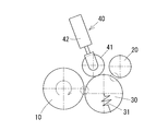
- the schematic diagram which shows 1st embodiment of the friction drive pulley mechanism based on this invention which shows the state which is not pressing the idler pulley with a movable pulley The schematic diagram which shows 1st embodiment of the friction drive pulley mechanism based on this invention which shows the state which pressed the idler pulley with the movable pulley
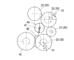
- the schematic diagram which shows 2nd embodiment of the friction drive pulley mechanism which concerns on this invention which shows the state which is not pressing any idler pulleys with a movable pulley
- the schematic diagram which shows 2nd embodiment of the friction drive pulley mechanism which concerns on this invention which shows the state which pressed the 1st idler pulley with the movable pulley
- the schematic diagram which shows 2nd embodiment of the friction drive pulley mechanism based on this invention which shows the state which pressed the 2nd idler pulley with the movable pulley.
- the schematic diagram which shows 3rd embodiment of the friction drive pulley mechanism which concerns on this invention which shows the state which is not pressing any idler pulleys with a movable pulley
- the schematic diagram which shows 3rd embodiment of the friction drive pulley mechanism based on this invention which shows the state which pressed the 1st idler pulley with the movable pulley.
- the schematic diagram which shows 3rd embodiment of the friction drive pulley mechanism based on this invention which shows the state which pressed the 2nd idler pulley with the movable pulley.
- FIG. 1A and 1B show a first embodiment of a friction drive pulley mechanism according to the present invention.
- FIG. 1A shows a state in which the idler pulley 30 is not pressed by the movable pulley 41
- FIG. 1B shows a state in which the idler pulley 30 is pressed by the movable pulley 41.
- the friction drive pulley mechanism includes a drive pulley 10 connected to an engine crankshaft, a driven pulley 20 for operating auxiliary equipment such as a water pump (WP) and an idling stop generator (ISG), the drive pulley 10 and a driven pulley.
- An idler pulley 30 that is interposed between the pulley 20 and abuts against the drive pulley 10 and the driven pulley 20 and transmits the rotational force of the drive pulley 10 to the driven pulley 20 by a frictional force accompanying the contact, and the idler pulley.
- An idler pulley pressing mechanism 40 capable of contacting the outer diameter surface 30 is provided.
- the idler pulley 30 is provided with a biasing member 31 that biases the idler pulley 30 toward the drive pulley 10 and the driven pulley 20.
- a biasing member 31 that biases the idler pulley 30 toward the drive pulley 10 and the driven pulley 20.
- the urging force of the urging member 31 causes the outer diameter surface of the idler pulley 30, the drive pulley 10, and the driven pulley 20.
- Each of the outer diameter surfaces of each of them is in contact with each other evenly. In this contact state, when the driving pulley 10 is rotated clockwise as indicated by an arrow in FIG.
- the idler pulley 30 rotates counterclockwise and the driven pulley 20 rotates clockwise, and the rotational force of the driving pulley 10 is increased. It is transmitted to the driven pulley 20.
- a coil spring can be employed as the biasing member 31 provided in the idler pulley 30.
- the idler pulley pressing mechanism 40 includes a movable pulley 41 that contacts the outer diameter surface of the idler pulley 30, and a linear actuator (drive device) 42 that moves the movable pulley 41 back and forth in one direction.
- the movable pulley 41 is provided at the tip of the rod of the direct acting actuator 42 so as to be rotatable around an axis. When the movable pulley 41 contacts the idler pulley 30 that rotates about the axis, the movable pulley 41 rotates in the direction opposite to the rotational direction of the idler pulley 30 by receiving the rotational force.
- 1B shows a state in which both the idler pulley 30 and the driving pulley 10 and the driven pulley 20 are separated from each other. However, either the idler pulley 30 and the driving pulley 10 or the idler pulley 30 and the driven pulley 20 are shown. If one of them is separated, the effect of blocking the rotational force from the driving pulley 10 to the driven pulley 20 is exhibited.
- the contact position of the movable pulley 41 with the idler pulley 30 may be in contact with any part as long as it is within the range of contact positions of the idler pulley 30, the drive pulley 10, and the driven pulley 20. It is preferable that the urging shaft of the urging member 31 that urges 30 and the drive shaft of the linear actuator 42 coincide. Thus, by making the directions of both shafts coincide with each other, the idler pulley 30 can be moved efficiently by pressing the idler pulley 30 efficiently with the pressing force of the linear actuator 42.
- FIG. 2A to 2C show a second embodiment of a friction drive pulley mechanism according to the present invention.
- 2A is a state in which neither the first idle pulley 32 nor the second idler pulley 33 is pressed by the movable pulley 41
- FIG. 2B is a state in which the first idler pulley 32 is pressed by the movable pulley 41
- FIG. The second idler pulley 33 is pressed.
- the friction drive pulley mechanism includes a drive pulley 10 connected to an engine crankshaft, a first driven pulley 21 and a second driven pulley 22 for operating accessories such as WP, and the drive pulley 10 and the first driven pulley. 21, the first idler pulley 32 interposed between the first driven pulley 21 and the second driven pulley 22, and the outer diameter surfaces of both idler pulleys 32, 33.
- An idler pulley pressing mechanism 40 that can be contacted is provided.
- the first idler pulley 32 and the second idler pulley 33 the first idler pulley 32 is directed toward the drive pulley 10 and the first driven pulley 21, and the second idler pulley 33 is directed to the first driven pulley 21 and the second driven pulley.
- the urging members 31 that urge each toward the pulley 22 are provided. As shown in FIG. 2A, when the idler pulleys 32 and 33 are not pressed by the movable pulley 41 described later, the urging force of the urging member 31 causes the outer diameter surface of the first idler pulley 32 and the drive pulley.
- the idler pulley pressing mechanism 40 includes a movable pulley 41 that can be selectively brought into contact with the outer diameter surface of either the first idler pulley 32 or the second idler pulley 33 in order, and the movable pulley 41 that has a swing shaft 44.
- a swing actuator (swing device) 43 that swings around is provided.
- the movable pulley 41 is provided at the tip of the rod of the swing actuator 43 so as to be swingable around the swing shaft 44.
- the first idler pulley 32 moves against the urging force of the urging member 31 provided on the first idler pulley 32, as shown in FIG. 2B.
- the first idler pulley 32 and the drive pulley 10 are separated (see the portion surrounded by the dotted circle in FIG. 2B), and the rotation of the drive pulley 10 is caused by the first idler pulley 32 and the first driven pulley. 21, the second idler pulley 33, and the second driven pulley 22 are not transmitted.
- the movable pulley 41 swings around the swing shaft 44 and comes into contact with the second idler pulley 33, the movable pulley 41 receives the rotational force of the second idler pulley 33, and the movable pulley 41 receives the second idler pulley 33. It rotates in the direction opposite to the rotation direction.
- the second idler pulley 33 moves against the biasing force of the biasing member 31 provided on the second idler pulley 33, as shown in FIG. 2C.
- the second idler pulley 33 and the second driven pulley 22 are separated from each other (see the portion surrounded by a dotted circle in FIG. 2C), and the rotation of the drive pulley 10 is caused by the first idler pulley 32 and the first idler pulley 32. While being transmitted to the driven pulley 21 and the second idler pulley 33, they are not transmitted to the second driven pulley 22.
- FIG. 2B shows a state in which only the drive pulley 10 and the first idler pulley 32 are separated (see a portion surrounded by a dotted circle in FIG. 2B), but the first idler pulley 32 and the drive pulley are shown. 10 and the first driven pulley 21 may be separated from each other.
- FIG. 2C shows a state in which only the second idler pulley 33 and the second driven pulley 22 are separated from each other (see a portion surrounded by a dotted circle in FIG. 2C). The first driven pulley 21 and the second driven pulley 22 may be separated from each other.
- the contact position of the movable pulley 41 to the first idler pulley 32 and the second idler pulley 33 is within the range of the contact position of the first idler pulley 32, the drive pulley 10, and the first driven pulley 21, or the second idler pulley.
- the pulley 33 and the first driven pulley 21 and the second driven pulley 22 may be in contact with any portion as long as they are within the range of the contact positions, but the idler pulleys 32 and 33 are placed on the contact positions. It is preferable that the biasing shaft of the biasing member 31 to be biased passes. In this way, the idler pulleys 32 and 33 can be efficiently pressed by the pressing force of the linear actuator 43, and the idler pulleys 32 and 33 can be moved quickly.
- FIG. 3A to 3C show a third embodiment of the friction drive pulley mechanism according to the present invention.
- FIG. 3A shows a state in which neither the first idle pulley 32 nor the second idler pulley 33 is pressed by the movable pulley 41
- FIG. 3B shows a state in which the first idler pulley 32 is pressed by the movable pulley 41
- FIG. The second idler pulley 33 is pressed.
- the friction drive pulley mechanism includes a drive pulley 10 connected to an engine crankshaft, a first driven pulley 21 and a second driven pulley 22 for operating accessories such as WP, and the drive pulley 10 and the first driven pulley. 21, the first idler pulley 32 interposed between the first driven pulley 21 and the second driven pulley 22, and the outer diameter surfaces of both idler pulleys 32, 33.
- An idler pulley pressing mechanism 40 that can be contacted is provided.
- the idler pulley pressing mechanism 40 includes a movable pulley 41 that can be selectively brought into contact with the outer diameter surface of either the first idler pulley 32 or the second idler pulley 33, and the movable pulley 41 is advanced and retracted in one direction. And a linear motion actuator 42 (drive device 42).
- the movable pulley 41 is provided at the tip of the rod of the direct acting actuator 42 so as to be rotatable around an axis. When the movable pulley 41 contacts the first idler pulley 32 that rotates about the axis, the movable pulley 41 rotates in the direction opposite to the rotational direction of the first idler pulley 32 by receiving the rotational force of the first idler pulley 32. .
- the first idler pulley 32 moves against the urging force of the urging member 31 provided on the first idler pulley 32, as shown in FIG. 3B.
- the first idler pulley 32 and the drive pulley 10 are separated from each other (see the portion surrounded by the dotted circle in FIG. 3B), and the rotation of the drive pulley 10 is caused by the first idler pulley 32, the first driven pulley 21, It is not transmitted to the second idler pulley 33 and the second driven pulley 22.
- the movable pulley 41 when the movable pulley 41 comes into contact with the second idler pulley 33 rotating around the axis, the movable pulley 41 receives the rotational force of the second idler pulley 33 and the movable pulley 41 is in the direction opposite to the rotational direction of the second idler pulley 33. Rotate to.
- the second idler pulley 33 moves against the biasing force of the biasing member 31 provided on the second idler pulley 33, as shown in FIG. 3C.
- the second idler pulley 33 and the second driven pulley 22 are separated from each other (see the portion surrounded by the dotted circle in FIG. 3C), and the drive pulley 10 is rotated by the first idler pulley 32 and the first driven pulley. 21 and the second idler pulley 33, but not transmitted to the second driven pulley 22.
- FIG. 3B shows a state in which only the drive pulley 10 and the first idler pulley 32 are separated (see the portion surrounded by a dotted circle in FIG. 3B), but the first idler pulley 32 and the drive pulley are shown. 10 and the first driven pulley 21 may be separated from each other.
- FIG. 3C shows a state in which only the second idler pulley 33 and the second driven pulley 22 are separated from each other (see the portion surrounded by a dotted circle in FIG. 3C). The first driven pulley 21 and the second driven pulley 22 may be separated from each other.
- the contact position of the movable pulley 41 to the first idler pulley 32 and the second idler pulley 33 is within the range of the contact position of the first idler pulley 32, the drive pulley 10, and the first driven pulley 21, or the second idler pulley.
- the pulley 33 and the first driven pulley 21 and the second driven pulley 22 may be in contact with any portion as long as they are within the range of the contact positions, but the idler pulleys 32 and 33 are placed on the contact positions. It is preferable that the biasing shaft of the biasing member 31 to be biased passes. In this way, the idler pulleys 32 and 33 can be efficiently pressed by the pressing force of the linear actuator 43, and the idler pulleys 32 and 33 can be moved quickly.
- the friction drive pulley mechanism according to each of the above embodiments is merely an example, and the idler pulley interposed between the drive pulley 10 and the driven pulley 20 while reliably transmitting the rotational force between the drive pulley 10 and the driven pulley 20.
- the movable pulley 41 is configured to be able to contact the two idler pulleys 30 (the first idler pulley 32 and the second idler pulley 33). As long as one movable pulley 41 can be brought into contact with three or more idler pulleys 30 as long as possible.
Landscapes
- Engineering & Computer Science (AREA)
- General Engineering & Computer Science (AREA)
- Mechanical Engineering (AREA)
- Friction Gearing (AREA)
Abstract
駆動プーリ(10)と従動プーリ(20)との間に介在して、付勢手段による付勢力によって駆動プーリ(10)及び従動プーリ(20)に当接し、駆動プーリ(10)の回転力をこの当接に伴う摩擦力によって従動プーリ(20)に伝達するアイドラプーリ(30)を備えたフリクションドライブプーリ機構において、アイドラプーリ(30)の外径面を、前記付勢力に抗してその径方向中心向きに押圧し、アイドラプーリ(30)と、駆動プーリ(10)及び従動プーリ(20)のうち少なくとも一方との当接を解除させるアイドラプーリ押圧機構(40)を備えた。
Description
この発明は、駆動プーリと従動プーリとの間に介在して、駆動プーリの回転力を摩擦力によって従動プーリに伝達するアイドラプーリを備えたフリクションドライブプーリ機構に関する。
従来、エンジンの動力伝達機構においては、エンジンのクランクと、ウォータポンプ(WP)やアイドリングストップジェネレータ(ISG)等の補機類との間の動力の伝達を、アイドラプーリを経由して架け渡した補機ベルトを介して行っていた。この場合、クランクの回転に伴って、補機類も常に回転することになるため、例えば、エンジンの暖気運転のようにWPを回転させる必要がない時にも不必要に回転することになり、ベルト損失とプーリの不必要な回転に起因する燃費の低下が問題となっていた。
この問題を解決すべく、例えば、下記特許文献1の図1には、補機ベルトを用いる代わりに、クランクシャフトプーリ4(駆動プーリ)とフリクションプーリ14(従動プーリ)との間にフリクションホイール17(アイドラプーリ)を介在させ、クランクシャフトプーリ4の回転力を、フリクションホイール17の摩擦力によって、フリクションプーリ14に伝達する構成が採用されている。フリクションホイール17は軸周りに回転するため、このフリクションホイール17の回転中心となる駆動軸15(非回転部分)に、アーム16が設けられている。アーム16には作動装置18が設けられており、この作動装置18によってアーム16に設けられたフリクションホイール17を移動させることで、フリクションホイール17とクランクシャフトプーリ4及びフリクションプーリ14との当接状態を自在に変えることができる。このように、当接状態を変えることにより、クランクシャフトプーリ4とフリクションプーリ14との間の回転力の伝達又は非伝達を自在に変更することができる。
特許文献1の図1に記載の機構においては、アーム16が、フリクションホイール17の非回転部分、すなわち駆動軸15に取り付けられている。このため、アーム16は駆動軸15の軸方向に突出した状態となっており、このアーム16の厚みの分だけ、駆動軸15の軸方向への肉厚化が避けられないという問題がある。この肉厚化を阻止するために、フリクションホイール17を薄肉化することも考えられる。しかしながら、クランクシャフトプーリ4とフリクションプーリ14との間で確実に回転力を伝達するためには、フリクションホイール17による十分な摩擦力が必要であり、フリクションホイール17の薄肉化は、摩擦力の確保の点から好ましくない。
また、フリクションホイール17を移動させる可動装置を、プーリの内部に収納した構成とすることも考えられる。しかしながら、クランクシャフトプーリ4とフリクションプーリ14との間で確実に回転力を伝達するためには、ある程度駆動力の大きい可動装置を用いてフリクションホイール17を両プーリ4、14に当接させる必要があり、フリクションホイール17の小型化を図るのは容易ではない。
このように、フリクションホイール17の薄肉化、小型化ができないことによって、補機駆動システムのレイアウトが制約を受けるという問題が生じることがある。
そこで、この発明は、駆動プーリ及び従動プーリとの間で、確実に回転力を伝達しつつ、駆動プーリ及び従動プーリに介在するアイドラプーリの駆動機構の小型化を図ることを課題とする。
この課題を解決するために、この発明においては、駆動プーリと従動プーリとの間に介在して、付勢手段による付勢力によって前記駆動プーリ及び前記従動プーリに当接し、前記駆動プーリの回転力をこの当接に伴う摩擦力によって前記従動プーリに伝達するアイドラプーリを備えたフリクションドライブプーリ機構において、前記アイドラプーリの外径面を、前記付勢力に抗してその径方向中心向きに押圧し、前記アイドラプーリと、前記駆動プーリ及び前記従動プーリのうち少なくとも一方との当接を解除させるアイドラプーリ押圧機構を備えたことを特徴とするフリクションドライブプーリ機構を構成した。
このように、アイドラプーリ押圧機構をアイドラプーリの外径面に押圧して、アイドラプーリを移動させる構成とすることにより、このアイドラプーリや駆動プーリ等が配置されているのと同一の平面内で押圧力の伝達を行うことができる。このため、アイドラプーリの非回転部分である軸心に、その駆動機構を設けた場合と比較して、アイドラプーリ押圧機構の薄肉化及び小型化を図ることができる。
前記構成においては、前記アイドラプーリ押圧機構が、前記アイドラプーリに当接する可動プーリと、この可動プーリを一方向に進退させる駆動装置とを備えた構成、又は、前記アイドラプーリ押圧機構が、前記アイドラプーリに当接する可動プーリと、この可動プーリを揺動軸周りに揺動させる揺動装置とを備えた構成とすることができる。
このように、軸周りに回転可能な可動プーリをアイドラプーリ押圧機構に採用することによって、アイドラプーリが回転状態にあっても、このアイドラプーリを所定方向にスムーズに押圧することができる。
アイドラプーリ押圧機構に可動プーリを採用した構成においては、前記アイドラプーリを複数備え、前記可動プーリが、複数の前記アイドラプーリの一つに順次選択的に当接可能となっており、前記可動プーリが当接したアイドラプーリと、このアイドラプーリと当接可能に配置された前記駆動プーリ及び前記従動プーリのうち少なくとも一方との当接を解除するようにした構成とすることができる。
このように、可動プーリが複数のアイドラプーリに順次選択的に当接可能とすることにより、一つのアイドラプーリ押圧機構で、複数のアイドラプーリを制御することができ効率が高い。
前記各構成においては、前記アイドラプーリの外径面に弾性体を設けた構成とすることができる。
このように、外径面に弾性体を設けることにより、アイドラプーリと駆動プーリ及び従動プーリとの間の滑りを防止して、駆動プーリと従動プーリとの間で、損失なく回転力を伝達することができる。
この発明においては、駆動プーリと従動プーリとの間に介在して、付勢手段による付勢力によって前記駆動プーリ及び前記従動プーリに当接し、前記駆動プーリの回転力をこの当接に伴う摩擦力によって前記従動プーリに伝達するアイドラプーリを備えたフリクションドライブプーリ機構において、前記アイドラプーリの外径面を、前記付勢力に抗してその径方向中心向きに押圧し、前記アイドラプーリと、前記駆動プーリ及び前記従動プーリのうち少なくとも一方との当接を解除させるアイドラプーリ押圧機構を備えたことを特徴とするフリクションドライブプーリ機構を構成した。
このように、アイドラプーリ押圧機構をアイドラプーリの外径面に押圧して、アイドラプーリを移動させる構成とすることにより、このアイドラプーリや駆動プーリ等が配置されているのと同一の平面内で押圧力の伝達を行うことができる。このため、アイドラプーリの非回転部分である軸心に、その駆動機構を設けた場合と比較して、アイドラプーリ押圧機構の薄肉化及び小型化を図ることができる。
この発明に係るフリクションドライブプーリ機構の第一実施形態を図1A、図1Bに示す。図1Aは可動プーリ41でアイドラプーリ30を押圧していない状態、図1Bは可動プーリ41でアイドラプーリ30を押圧した状態である。
このフリクションドライブプーリ機構は、エンジンのクランクシャフトに接続された駆動プーリ10と、ウォータポンプ(WP)やアイドリングストップジェネレータ(ISG)等の補機類を作動させる従動プーリ20と、駆動プーリ10及び従動プーリ20との間に介在して、駆動プーリ10及び従動プーリ20に当接し、駆動プーリ10の回転力をこの当接に伴う摩擦力によって従動プーリ20に伝達するアイドラプーリ30と、このアイドラプーリ30の外径面に当接可能とした、アイドラプーリ押圧機構40を備えている。
アイドラプーリ30には、このアイドラプーリ30を駆動プーリ10及び従動プーリ20に向けて付勢する付勢部材31が設けられている。図1Aに示すように、後述する可動プーリ41でアイドラプーリ30を押圧していない状態では、この付勢部材31の付勢力によって、アイドラプーリ30の外径面と、駆動プーリ10及び従動プーリ20のそれぞれの外径面とが均等に当接する。この当接状態において、駆動プーリ10を図1A中に矢印で示すように右回りに回転すると、アイドラプーリ30が左回りに、従動プーリ20が右回りに回転し、駆動プーリ10の回転力が従動プーリ20に伝達される。なお、アイドラプーリ30に設ける付勢部材31として、例えばコイルばねを採用することができる。
アイドラプーリ押圧機構40は、アイドラプーリ30の外径面に当接する可動プーリ41と、この可動プーリ41を一方向に進退させる直動アクチュエータ(駆動装置)42とを備えている。可動プーリ41は、直動アクチュエータ42のロッドの先端に、軸周りに回転自在に設けられている。可動プーリ41が、軸周りに回転するアイドラプーリ30に接触すると、その回転力を受けて、可動プーリ41はアイドラプーリ30の回転方向と逆方向に回転する。この可動プーリ41をアイドラプーリ30側にさらに押し込むと、アイドラプーリ30に設けた付勢部材31の付勢力に抗して、アイドラプーリ30が移動し、図1Bに示すように、アイドラプーリ30と駆動プーリ10及び従動プーリ20とが離間して(図1B中の点線の丸で囲んだ部分を参照)、駆動プーリ10の回転は、アイドラプーリ30及び従動プーリ20に伝達されない。
なお、図1Bには、アイドラプーリ30と駆動プーリ10及び従動プーリ20の両方が離間した状態を示しているが、アイドラプーリ30と駆動プーリ10、又は、アイドラプーリ30と従動プーリ20のいずれか一方が離間すれば、駆動プーリ10から従動プーリ20への回転力の遮断作用は発揮される。
可動プーリ41のアイドラプーリ30への当接位置は、このアイドラプーリ30と駆動プーリ10及び従動プーリ20の当接位置の範囲内であればどの部分に当接していても構わないが、アイドラプーリ30を付勢する付勢部材31の付勢軸と直動アクチュエータ42の駆動軸が一致しているのが好ましい。このように両軸の方向を一致させることにより、直動アクチュエータ42の押圧力で、アイドラプーリ30を効率的に押圧して、速やかにアイドラプーリ30を移動させることができる。
この発明に係るフリクションドライブプーリ機構の第二実施形態を図2A~図2Cに示す。図2Aは可動プーリ41で第一及び第二アイドラプーリ32、33のいずれも押圧していない状態、図2Bは可動プーリ41で第一アイドラプーリ32を押圧した状態、図2Cは可動プーリ41で第二アイドラプーリ33を押圧した状態である。
このフリクションドライブプーリ機構は、エンジンのクランクシャフトに接続された駆動プーリ10と、WP等の補機類を作動させる第一従動プーリ21及び第二従動プーリ22と、駆動プーリ10及び第一従動プーリ21との間に介在する第一アイドラプーリ32と、第一従動プーリ21及び第二従動プーリ22との間に介在する第二アイドラプーリ33と、両アイドラプーリ32、33の外径面に当接可能とした、アイドラプーリ押圧機構40を備えている。
第一アイドラプーリ32及び第二アイドラプーリ33には、第一アイドラプーリ32を駆動プーリ10及び第一従動プーリ21に向けて、及び、第二アイドラプーリ33を第一従動プーリ21及び第二従動プーリ22に向けてそれぞれ付勢する付勢部材31が設けられている。図2Aに示すように、後述する可動プーリ41で両アイドラプーリ32、33を押圧していない状態では、この付勢部材31の付勢力によって、第一アイドラプーリ32の外径面と、駆動プーリ10及び第一従動プーリ21のそれぞれの外径面とが、並びに、第二アイドラプーリ33の外径面と、第一従動プーリ21及び第二従動プーリ22のそれぞれの外径面とがそれぞれ均等に当接する。この当接状態において、駆動プーリ10を図2A中に矢印で示すように右回りに回転すると、第一アイドラプーリ32が左回りに、第一従動プーリ21が右回りに、第二アイドラプーリ33が左回りに、第二従動プーリ22が右回りにそれぞれ回転し、駆動プーリ10の回転力が第二従動プーリ22まで伝達される。
アイドラプーリ押圧機構40は、第一アイドラプーリ32又は第二アイドラプーリ33のいずれか一方の外径面に、順次選択的に当接可能な可動プーリ41と、この可動プーリ41を揺動軸44周りに揺動させる揺動アクチュエータ(揺動装置)43とを備えている。可動プーリ41は、揺動アクチュエータ43のロッドの先端に、揺動軸44周りに揺動自在に設けられている。可動プーリ41が揺動して第一アイドラプーリ32に接触すると、この第一アイドラプーリ32の回転力を受けて、可動プーリ41は第一アイドラプーリ32の回転方向と逆方向に回転する。この可動プーリ41を第一アイドラプーリ32側にさらに揺動させると、第一アイドラプーリ32に設けた付勢部材31の付勢力に抗して第一アイドラプーリ32が移動し、図2Bに示すように、第一アイドラプーリ32と駆動プーリ10とが離間して(図2B中の点線の丸で囲んだ部分を参照)、駆動プーリ10の回転は、第一アイドラプーリ32、第一従動プーリ21、第二アイドラプーリ33、及び第二従動プーリ22に伝達されない。
その一方で、可動プーリ41が揺動軸44周りに揺動して第二アイドラプーリ33に接触すると、この第二アイドラプーリ33の回転力を受けて、可動プーリ41は第二アイドラプーリ33の回転方向と逆方向に回転する。この可動プーリ41を第二アイドラプーリ33側にさらに揺動させると、第二アイドラプーリ33に設けた付勢部材31の付勢力に抗して第二アイドラプーリ33が移動し、図2Cに示すように、第二アイドラプーリ33と第二従動プーリ22とが離間して(図2C中の点線の丸で囲んだ部分を参照)、駆動プーリ10の回転は、第一アイドラプーリ32、第一従動プーリ21、及び第二アイドラプーリ33まで伝達される一方で、第二従動プーリ22には伝達されない。
なお、図2Bには、駆動プーリ10と第一アイドラプーリ32のみが離間した状態を示しているが(図2B中の点線の丸で囲んだ部分を参照)、第一アイドラプーリ32と駆動プーリ10及び第一従動プーリ21の両方が離間した状態としてもよい。同様に、図2Cには、第二アイドラプーリ33と第二従動プーリ22のみが離間した状態を示しているが(図2C中の点線の丸で囲んだ部分を参照)、第二アイドラプーリ33と第一従動プーリ21及び第二従動プーリ22の両方が離間した状態としてもよい。
可動プーリ41の第一アイドラプーリ32及び第二アイドラプーリ33への当接位置は、第一アイドラプーリ32と駆動プーリ10及び第一従動プーリ21の当接位置の範囲内、又は、第二アイドラプーリ33と第一従動プーリ21及び第二従動プーリ22の当接位置の範囲内であればどの部分に当接していても構わないが、この当接位置上に、各アイドラプーリ32、33を付勢する付勢部材31の付勢軸が通っているのが好ましい。このようにすることにより、直動アクチュエータ43の押圧力で、各アイドラプーリ32、33を効率的に押圧して、速やかに各アイドラプーリ32、33を移動させることができる。
この発明に係るフリクションドライブプーリ機構の第三実施形態を図3A~図3Cに示す。図3Aは可動プーリ41で第一及び第二アイドラプーリ32、33のいずれも押圧していない状態、図3Bは可動プーリ41で第一アイドラプーリ32を押圧した状態、図3Cは可動プーリ41で第二アイドラプーリ33を押圧した状態である。
このフリクションドライブプーリ機構は、エンジンのクランクシャフトに接続された駆動プーリ10と、WP等の補機類を作動させる第一従動プーリ21及び第二従動プーリ22と、駆動プーリ10及び第一従動プーリ21との間に介在する第一アイドラプーリ32と、第一従動プーリ21及び第二従動プーリ22との間に介在する第二アイドラプーリ33と、両アイドラプーリ32、33の外径面に当接可能とした、アイドラプーリ押圧機構40を備えている。
アイドラプーリ押圧機構40は、第一アイドラプーリ32又は第二アイドラプーリ33のいずれか一方の外径面に、順次選択的に当接可能な可動プーリ41と、この可動プーリ41を一方向に進退させる直動アクチュエータ42(駆動装置42)とを備えている。可動プーリ41は、直動アクチュエータ42のロッドの先端に、軸周りに回転自在に設けられている。可動プーリ41が、軸周りに回転する第一アイドラプーリ32に接触すると、この第一アイドラプーリ32の回転力を受けて、可動プーリ41は第一アイドラプーリ32の回転方向と逆方向に回転する。この可動プーリ41を第一アイドラプーリ32側にさらに押し込むと、第一アイドラプーリ32に設けた付勢部材31の付勢力に抗して第一アイドラプーリ32が移動し、図3Bに示すように、第一アイドラプーリ32と駆動プーリ10とが離間して(図3B中の点線の丸で囲んだ部分を参照)、駆動プーリ10の回転は、第一アイドラプーリ32、第一従動プーリ21、第二アイドラプーリ33、及び第二従動プーリ22に伝達されない。
その一方で、可動プーリ41が軸周りに回転する第二アイドラプーリ33に接触すると、この第二アイドラプーリ33の回転力を受けて、可動プーリ41は第二アイドラプーリ33の回転方向と逆方向に回転する。この可動プーリ41を第二アイドラプーリ33側にさらに押し込むと、第二アイドラプーリ33に設けた付勢部材31の付勢力に抗して第二アイドラプーリ33が移動し、図3Cに示すように、第二アイドラプーリ33と第二従動プーリ22とが離間して(図3C中の点線の丸で囲んだ部分を参照)、駆動プーリ10の回転は、第一アイドラプーリ32、第一従動プーリ21、及び第二アイドラプーリ33まで伝達される一方で、第二従動プーリ22には伝達されない。
なお、図3Bには、駆動プーリ10と第一アイドラプーリ32のみが離間した状態を示しているが(図3B中の点線の丸で囲んだ部分を参照)、第一アイドラプーリ32と駆動プーリ10及び第一従動プーリ21の両方が離間した状態としてもよい。同様に、図3Cには、第二アイドラプーリ33と第二従動プーリ22のみが離間した状態を示しているが(図3C中の点線の丸で囲んだ部分を参照)、第二アイドラプーリ33と第一従動プーリ21及び第二従動プーリ22の両方が離間した状態としてもよい。
可動プーリ41の第一アイドラプーリ32及び第二アイドラプーリ33への当接位置は、第一アイドラプーリ32と駆動プーリ10及び第一従動プーリ21の当接位置の範囲内、又は、第二アイドラプーリ33と第一従動プーリ21及び第二従動プーリ22の当接位置の範囲内であればどの部分に当接していても構わないが、この当接位置上に、各アイドラプーリ32、33を付勢する付勢部材31の付勢軸が通っているのが好ましい。このようにすることにより、直動アクチュエータ43の押圧力で、各アイドラプーリ32、33を効率的に押圧して、速やかに各アイドラプーリ32、33を移動させることができる。
上記各実施形態に係るフリクションドライブプーリ機構はあくまでも一例であって駆動プーリ10及び従動プーリ20との間で、確実に回転力を伝達しつつ、駆動プーリ10及び従動プーリ20に介在するアイドラプーリの駆動機構の小型化を図る、という本願発明の課題を解決し得る限りにおいて、各構成部品の形状や配置を変更したり、別途部品を追加したりすることも許容される。また、第二及び第三実施形態においては、可動プーリ41が二個のアイドラプーリ30(第一アイドラプーリ32、第二アイドラプーリ33)と当接可能な構成としたが、スペース的に許容される限りにおいて、一つの可動プーリ41が三個以上のアイドラプーリ30と当接可能な構成とすることもできる。
10 駆動プーリ
20 従動プーリ
21 第一従動プーリ
22 第二従動プーリ
30 アイドラプーリ
31 付勢部材
32 第一アイドラプーリ
33 第二アイドラプーリ
40 アイドラプーリ押圧機構
41 可動プーリ
42 駆動装置(直動アクチュエータ)
43 揺動装置(揺動アクチュエータ)
44 揺動軸
20 従動プーリ
21 第一従動プーリ
22 第二従動プーリ
30 アイドラプーリ
31 付勢部材
32 第一アイドラプーリ
33 第二アイドラプーリ
40 アイドラプーリ押圧機構
41 可動プーリ
42 駆動装置(直動アクチュエータ)
43 揺動装置(揺動アクチュエータ)
44 揺動軸
Claims (5)
- 駆動プーリ(10)と従動プーリ(20)との間に介在して、付勢手段(31)による付勢力によって前記駆動プーリ(10)及び前記従動プーリ(20)に当接し、前記駆動プーリ(10)の回転力をこの当接に伴う摩擦力によって前記従動プーリ(20)に伝達するアイドラプーリ(30)を備えたフリクションドライブプーリ機構において、
前記アイドラプーリ(30)の外径面を、前記付勢力に抗してその径方向中心向きに押圧し、前記アイドラプーリ(30)と、前記駆動プーリ(10)及び前記従動プーリ(20)のうち少なくとも一方との当接を解除させるアイドラプーリ押圧機構(40)を備えたことを特徴とするフリクションドライブプーリ機構。 - 前記アイドラプーリ押圧機構(40)が、前記アイドラプーリ(30)に当接する可動プーリ(41)と、この可動プーリ(41)を一方向に進退させる駆動装置(42)と、を備えたことを特徴とする請求項1に記載のフリクションドライブプーリ機構。
- 前記アイドラプーリ押圧機構(40)が、前記アイドラプーリ(30)に当接する可動プーリ(41)と、この可動プーリ(41)を揺動軸(44)周りに揺動させる揺動装置(43)と、を備えたことを特徴とする請求項1に記載のフリクションドライブプーリ機構。
- 前記アイドラプーリ(30)を複数備え、前記可動プーリ(41)が、複数の前記アイドラプーリ(30)の一つに順次選択的に当接可能となっており、前記可動プーリ(41)が当接したアイドラプーリ(30)と、このアイドラプーリ(30)と当接可能に配置された前記駆動プーリ(10)及び前記従動プーリ(20)のうち少なくとも一方との当接を解除するようにしたことを特徴とする請求項2又は3に記載のフリクションドライブプーリ機構。
- 前記アイドラプーリ(30)の外径面に弾性体を設けたことを特徴とする請求項1から4のいずれか1項に記載のフリクションドライブプーリ機構。
Applications Claiming Priority (2)
| Application Number | Priority Date | Filing Date | Title |
|---|---|---|---|
| JP2015-032856 | 2015-02-23 | ||
| JP2015032856A JP2016156396A (ja) | 2015-02-23 | 2015-02-23 | フリクションドライブプーリ機構 |
Publications (1)
| Publication Number | Publication Date |
|---|---|
| WO2016136498A1 true WO2016136498A1 (ja) | 2016-09-01 |
Family
ID=56788453
Family Applications (1)
| Application Number | Title | Priority Date | Filing Date |
|---|---|---|---|
| PCT/JP2016/054114 Ceased WO2016136498A1 (ja) | 2015-02-23 | 2016-02-12 | フリクションドライブプーリ機構 |
Country Status (2)
| Country | Link |
|---|---|
| JP (1) | JP2016156396A (ja) |
| WO (1) | WO2016136498A1 (ja) |
Cited By (1)
| Publication number | Priority date | Publication date | Assignee | Title |
|---|---|---|---|---|
| CN112943878A (zh) * | 2019-12-10 | 2021-06-11 | 深圳顺丰泰森控股(集团)有限公司 | 减速机 |
Citations (4)
| Publication number | Priority date | Publication date | Assignee | Title |
|---|---|---|---|---|
| JPS4118970B1 (ja) * | 1964-02-26 | 1966-11-02 | ||
| JPS468504Y1 (ja) * | 1966-12-20 | 1971-03-25 | ||
| JPS56119046U (ja) * | 1980-02-13 | 1981-09-10 | ||
| DE10314258A1 (de) * | 2003-03-29 | 2004-11-11 | Ina-Schaeffler Kg | Reibradantrieb |
-
2015
- 2015-02-23 JP JP2015032856A patent/JP2016156396A/ja not_active Withdrawn
-
2016
- 2016-02-12 WO PCT/JP2016/054114 patent/WO2016136498A1/ja not_active Ceased
Patent Citations (4)
| Publication number | Priority date | Publication date | Assignee | Title |
|---|---|---|---|---|
| JPS4118970B1 (ja) * | 1964-02-26 | 1966-11-02 | ||
| JPS468504Y1 (ja) * | 1966-12-20 | 1971-03-25 | ||
| JPS56119046U (ja) * | 1980-02-13 | 1981-09-10 | ||
| DE10314258A1 (de) * | 2003-03-29 | 2004-11-11 | Ina-Schaeffler Kg | Reibradantrieb |
Cited By (1)
| Publication number | Priority date | Publication date | Assignee | Title |
|---|---|---|---|---|
| CN112943878A (zh) * | 2019-12-10 | 2021-06-11 | 深圳顺丰泰森控股(集团)有限公司 | 减速机 |
Also Published As
| Publication number | Publication date |
|---|---|
| JP2016156396A (ja) | 2016-09-01 |
Similar Documents
| Publication | Publication Date | Title |
|---|---|---|
| JP6453127B2 (ja) | 自転車のドライブユニット | |
| TWI701400B (zh) | 離心離合器 | |
| JP2011106613A5 (ja) | ||
| CN103459890B (zh) | 带式无级变速器 | |
| US10746267B2 (en) | Toroidal continuously variable transmission | |
| JP2016182850A (ja) | 自転車の変速装置 | |
| WO2016136498A1 (ja) | フリクションドライブプーリ機構 | |
| JP5925671B2 (ja) | エンジン駆動ヒートポンプ | |
| RU2011124245A (ru) | Бесступенчатая трансмиссия фрикционного типа | |
| KR101810690B1 (ko) | 차량엔진 스타터 모터의 동력전달기구 | |
| JP6352128B2 (ja) | 動力伝達ローラ | |
| JP2004286117A (ja) | 二方向クラッチ | |
| JP2016023680A (ja) | 一方向クラッチ | |
| JP2004316881A (ja) | 楔ローラ伝動装置の伝動ローラ支持機構 | |
| JP6424960B2 (ja) | 車両用補機駆動装置 | |
| JP2017198243A (ja) | 車両用無段変速機 | |
| JP2017002931A (ja) | 動力伝達ローラ | |
| US1396821A (en) | Planetary transmission | |
| US1415150A (en) | Clutch mechanism | |
| JP2013210080A5 (ja) | ||
| JP6501224B2 (ja) | プーリ装置 | |
| JP2007263285A (ja) | 無段変速機用アクチュエータ | |
| JPWO2016199186A6 (ja) | 車両用補機駆動装置 | |
| JP2012112501A (ja) | 係合装置 | |
| JP2007263284A (ja) | 無段変速機用アクチュエータ |
Legal Events
| Date | Code | Title | Description |
|---|---|---|---|
| 121 | Ep: the epo has been informed by wipo that ep was designated in this application |
Ref document number: 16755245 Country of ref document: EP Kind code of ref document: A1 |
|
| NENP | Non-entry into the national phase |
Ref country code: DE |
|
| 122 | Ep: pct application non-entry in european phase |
Ref document number: 16755245 Country of ref document: EP Kind code of ref document: A1 |