WO2016136423A1 - 内面電子線照射装置 - Google Patents
内面電子線照射装置 Download PDFInfo
- Publication number
- WO2016136423A1 WO2016136423A1 PCT/JP2016/053442 JP2016053442W WO2016136423A1 WO 2016136423 A1 WO2016136423 A1 WO 2016136423A1 JP 2016053442 W JP2016053442 W JP 2016053442W WO 2016136423 A1 WO2016136423 A1 WO 2016136423A1
- Authority
- WO
- WIPO (PCT)
- Prior art keywords
- electron beam
- beam irradiation
- corrosion
- nozzle
- irradiation apparatus
- Prior art date
- Legal status (The legal status is an assumption and is not a legal conclusion. Google has not performed a legal analysis and makes no representation as to the accuracy of the status listed.)
- Ceased
Links
Images
Classifications
-
- A—HUMAN NECESSITIES
- A61—MEDICAL OR VETERINARY SCIENCE; HYGIENE
- A61L—METHODS OR APPARATUS FOR STERILISING MATERIALS OR OBJECTS IN GENERAL; DISINFECTION, STERILISATION OR DEODORISATION OF AIR; CHEMICAL ASPECTS OF BANDAGES, DRESSINGS, ABSORBENT PADS OR SURGICAL ARTICLES; MATERIALS FOR BANDAGES, DRESSINGS, ABSORBENT PADS OR SURGICAL ARTICLES
- A61L2/00—Disinfection or sterilisation of materials or objects, in general; Accessories therefor
- A61L2/02—Disinfection or sterilisation of materials or objects, in general; Accessories therefor using physical processes
- A61L2/08—Radiation
-
- B—PERFORMING OPERATIONS; TRANSPORTING
- B65—CONVEYING; PACKING; STORING; HANDLING THIN OR FILAMENTARY MATERIAL
- B65B—MACHINES, APPARATUS OR DEVICES FOR, OR METHODS OF, PACKAGING ARTICLES OR MATERIALS; UNPACKING
- B65B55/00—Preserving, protecting or purifying packages or package contents in association with packaging
- B65B55/02—Sterilising, e.g. of complete packages
- B65B55/04—Sterilising wrappers or receptacles prior to, or during, packaging
- B65B55/08—Sterilising wrappers or receptacles prior to, or during, packaging by irradiation
-
- G—PHYSICS
- G21—NUCLEAR PHYSICS; NUCLEAR ENGINEERING
- G21K—HANDLING OF PARTICLES OR IONISING RADIATION NOT OTHERWISE PROVIDED FOR; IRRADIATION DEVICES; GAMMA RAY OR X-RAY MICROSCOPES
- G21K5/00—Irradiation devices
-
- G—PHYSICS
- G21—NUCLEAR PHYSICS; NUCLEAR ENGINEERING
- G21K—HANDLING OF PARTICLES OR IONISING RADIATION NOT OTHERWISE PROVIDED FOR; IRRADIATION DEVICES; GAMMA RAY OR X-RAY MICROSCOPES
- G21K5/00—Irradiation devices
- G21K5/04—Irradiation devices with beam-forming means
Definitions
- the present invention relates to an inner surface electron beam irradiation apparatus for sterilizing the inner surface of an object to be sterilized such as a container by electron beam irradiation.
- equipment that irradiates a container with an electron beam is used as a facility for surely sterilizing the container.
- an outer surface electron beam irradiation device that irradiates the outer surface of the container with an electron beam, and an inner surface electron beam irradiation device that irradiates the inner surface of the container with an electron beam And are provided.
- the container is surely sterilized, but corrosive gases such as ozone and nitric acid are generated by a chemical reaction by the electron beam.
- a ventilator for promoting the discharge of the corrosive gas is also provided in the equipment.
- the inner surface electron beam irradiation apparatus irradiates the inner surface of the container with an electron beam from the exit window of the electron beam irradiation nozzle while inserting the electron beam irradiation nozzle into the container from the opening. Since the corrosive gas tends to remain inside the container even when the ventilator is operated, the electron beam irradiation nozzle is exposed to the corrosive gas. For this reason, the electron beam irradiation nozzle is more easily corroded than other devices and equipment of the facility. In order to prevent such corrosion, it is conceivable to apply a conventional technique (see, for example, Patent Document 1) to cover the emission window of the electron beam irradiation nozzle with a catalyst film.
- the corrosive gas remaining inside the container has a strong oxidizing power and cannot sufficiently prevent corrosion.
- the portion other than the exit window that is, the side surface of the electron beam irradiation nozzle
- the electron beam irradiation nozzle to which the above prior art is applied still has a short life.
- since corrosive gas with strong oxidizing power remains inside the container it is dangerous to discharge the container, which is the object of sterilization, outside the facility as it is.
- an object of the present invention is to provide an inner surface electron beam irradiation apparatus capable of extending the life.
- an inner surface electron beam irradiation apparatus is an inner surface electron beam irradiation apparatus that sterilizes an inner surface of an object to be sterilized with an opening formed by electron beam irradiation,
- An electron beam irradiation nozzle for irradiating an inner surface of the sterilization object with an electron beam while being inserted into the sterilization object from the opening is provided,
- the electron beam irradiation nozzle includes an emission window that emits an electron beam, a nozzle body that holds the emission window, and a protective film that covers the nozzle body.
- the inner surface electron beam irradiation apparatus according to claim 2 of the present invention has corrosion resistance on the entire surface of the portion in which the protective film in the inner surface electron beam irradiation apparatus according to claim 1 is inserted into the sterilization object.
- the portion inserted into the object to be sterilized has catalytic properties.
- a large number of protective films in the inner surface electron beam irradiation apparatus according to claim 2 are supported on the corrosion resistant layer having corrosion resistance and the outer surface of the corrosion resistant layer. And a catalytic body having catalytic properties.
- the inner surface electron beam irradiation apparatus according to claim 4 of the present invention is such that the corrosion-resistant layer in the inner surface electron beam irradiation apparatus according to claim 3 also has conductivity.
- the protective film includes an insulating layer disposed between the corrosion-resistant layer and the nozzle body, A charging power source for applying a voltage to the corrosion-resistant layer and the nozzle body is provided.
- the charging power source in the inner surface electron beam irradiation apparatus according to claim 4 applies a pulsed voltage to the corrosion-resistant layer and the nozzle body. is there.
- An inner surface electron beam irradiation apparatus is the inner surface electron beam irradiation apparatus according to any one of claims 2 to 5, wherein energy for improving the catalytic property of the protection film is applied to the protection film.
- the energy supply part which supplies to is provided.
- the life can be extended.
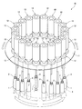
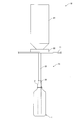
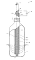
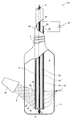
- FIG. 1 It is a schematic perspective view which shows the inner surface electron beam irradiation apparatus which concerns on embodiment of this invention. It is a schematic side view which shows the electron beam emitter of the inner surface electron beam irradiation apparatus. It is the partially cutaway side view which expanded the electron beam irradiation nozzle of the electron beam emitter, and the PET bottle in which this electron beam irradiation nozzle is inserted. It is a partially cutaway side view which shows the example in which the same inner surface electron beam irradiation apparatus was provided with the energy supply part.
- This electron beam sterilization facility is a facility that sterilizes by irradiating an electron beam while conveying an object to be sterilized in which an opening is formed.
- the sterilization target in which the opening is formed is, for example, a container such as a plastic bottle or a preform body.
- the preform body is a raw material body before being formed into a PET bottle by blow molding, and has a test tube shape.
- the sterilization object in which the opening is formed will be described as a PET bottle.
- the electron beam sterilization facility generally includes a transport device that continuously transports a large number of PET bottles from the upstream side to the downstream side, and an electron beam continuously on the outer surface of the PET bottle transported to the transport device. And an inner surface electron beam irradiation device that continuously irradiates the inner surface of the PET bottle transported to the transport device on the downstream side with the electron beam.
- the PET bottles that are insufficiently sterilized by electron beam irradiation need to be discarded as defective products.
- a reject device that performs this disposal is also provided in the electron beam sterilization facility.
- corrosive gases such as ozone and nitric acid are generated by the electron beam irradiation. Since this corrosive gas causes corrosion of each device of the electron beam sterilization facility, it must be discharged to the outside of the electron beam sterilization facility.
- a ventilation device that promotes the discharge is also provided in the electron beam sterilization facility.
- this inner surface electron beam irradiation device continuously sterilizes the inner surfaces of a large number of PET bottles 1 transported to the circular path 4 by the transport device.
- the inner surface electron beam irradiation device 10 is positioned above the circular path 4 and is concentric with the circular path 4.
- a large number of the turntables 11 are arranged on the turntable 11 and positioned immediately above the circular path 4.
- the electron beam emitter 12 mainly includes a vacuum chamber 21 whose inside is a vacuum atmosphere, a fixture 22 for fixing the vacuum chamber 21 to the turntable 11, and a downward direction from the vacuum chamber 21.
- An extending electron beam irradiation nozzle 23 is included.
- the vacuum chamber 21 is configured to generate a large number of electrons and accelerate downward by arranging an electron generation source therein.
- the electron beam irradiation nozzle 23 communicates with the vacuum chamber 21 and has a vacuum atmosphere inside.
- the electron beam irradiation nozzle 23 emits a large number of electrons accelerated in the vacuum chamber 21 from the lower end as an electron beam. Therefore, in order to sterilize the inner surface of the plastic bottle 1, the electron beam irradiation nozzle 23 is inserted into the interior of the plastic bottle 1 through the opening 2 as shown in FIGS. Must be irradiated with an electron beam. Therefore, an elevating device for inserting the electron beam irradiation nozzle 23 into the inside of the PET bottle 1 from the opening 2 by raising the PET bottle 1 from the circular path 4 is also provided in the electron beam sterilization facility, although not shown. It is done.
- the electron beam irradiation nozzle 23 has, as a conventional configuration, an emission window 31 that emits the electron beam 5 and a cylindrical nozzle body 32 that holds the emission window 31 at the lower end. .
- the electron beam irradiation nozzle 23 has a characteristic configuration of the present invention, and is a corrosion-resistant catalyst film (an example of a protective film) that covers the entire surface of the nozzle body 32 that is inserted into the interior 3 of the PET bottle 1. 33).
- the corrosion-resistant catalyst film 33 may cover the nozzle body 32 other than the portion inserted into the interior 3 of the plastic bottle 1.
- the corrosion-resistant catalyst film 33 has corrosion resistance on the entire surface of the portion inserted into the interior 3 of the PET bottle 1 and also has catalytic properties at the portion inserted into the interior 3 of the PET bottle 1. is there.
- the portion having the catalytic property may be a portion that is easily exposed to the corrosive gas remaining in the interior 3 of the PET bottle 1 for a relatively long time, specifically, a lower portion of the nozzle body 32. preferable.
- the corrosion-resistant catalyst film 33 is formed on, for example, a corrosion-resistant layer 34 that covers the nozzle body 32 over the entire surface inserted into the interior 3 of the PET bottle 1, and a lower outer surface of the corrosion-resistant layer 34.
- a large number of supported catalyst bodies 35 A material having higher corrosion resistance than the nozzle body 32 is used for the corrosion resistant layer 34. In order to increase the probability of contacting the corrosive gas, the large number of catalyst bodies 35 are arranged such that the distance between adjacent ones is constant.
- the corrosion-resistant layer 34 and the nozzle body 32 also have conductivity.
- the corrosion-resistant catalyst film 33 also includes an insulating layer 36 disposed between the corrosion-resistant layer 34 and the nozzle body 32 in order to insulate the corrosion-resistant layer 34 and the nozzle body 32.
- the inner surface electron beam irradiation apparatus 10 also includes a charging power source 14 that applies a voltage to the corrosion-resistant layer 34 and the nozzle body 32.
- the charging power source 14 charges the corrosion-resistant layer 34 positively and charges the nozzle body 32 negatively by applying the voltage.
- the positively charged corrosion-resistant layer 34 leads the corrosive gas to the catalyst body 35 by attracting the negatively charged corrosive gas by the electron beam 5.
- the voltage may be constant or pulsed. Since the voltage is pulsed, the corrosive gas is intermittently attracted by the corrosion-resistant layer 34, so that the probability of guiding the corrosive gas to the catalyst body 35 is increased.
- the negatively charged nozzle body 32 further converges the electron beam 5 passing through the nozzle body 32 toward the axial center side of the nozzle body 32 by repulsive force. Since the number of electrons passing through the unit area is further increased, the electron beam 5 further converged in this way further improves the efficiency of sterilization.
- the nozzle body 32 is made of a conventionally used material such as stainless steel.
- the corrosion-resistant layer 34 having the above conductivity a material having higher corrosion resistance than the nozzle body 32, for example, titanium, anodized aluminum or the like is used.
- the corrosion-resistant layer 34 having conductivity also includes iron, zirconium, molybdenum, rhodium, palladium, silver, tantalum, tungsten, iridium, platinum or gold, oxide, carbide, nitride, or these.
- An alloy containing two or more types is used.
- the corrosion-resistant layer 34 having conductivity may have a two-layer structure of an inner layer having conductivity and an outer layer having corrosion resistance.
- the inner layer having conductivity is copper or the like
- the outer layer having corrosion resistance is fluorine resin or the like.
- the catalyst body 35 is made of a simple substance such as titanium, lead, or cobalt, an oxide, or an alloy containing these.
- platinum, gold, palladium, rhodium, and iridium are used for the catalyst body 35.
- the insulating layer 36 is preferably made of a material having heat resistance and corrosion resistance, such as silicon, silicon oxide, glass, ceramic, or fluorine resin.
- the insulating layer 36 is preferably porous so that heat generated in the nozzle body 32 is easily released.
- a large number of PET bottles 1 with the opening 2 on the top are continuously transported to the circular path 4 below the inner surface electron beam irradiation device 10 by the transport device.
- the electron beam irradiation nozzle 23 is inserted into the inside 3 from the opening 2.
- the electron beam 5 is irradiated from the electron beam irradiation nozzle 23 to the inner surface of the PET bottle 1, as shown in FIG.
- the one in the inside of the PET bottle 1 is not easily discharged to the outside of the electron beam sterilization facility by the ventilator, and much remains as it is.
- the corrosive gas remaining in the inside 3 of the PET bottle 1 is rendered harmless by the catalytic property (specifically, the catalyst body 35) provided in the corrosion-resistant catalyst film 33 of the electron beam irradiation nozzle 23.
- the electron beam irradiation nozzle 23 inserted into the interior 3 of the PET bottle 1 does not corrode. Even if the corrosive gas is not completely detoxified, the electron beam irradiation nozzle 23 inserted into the interior 3 of the PET bottle 1 does not corrode due to the corrosion resistance of the corrosion-resistant catalyst film 33.
- corrosive gas is guided to the catalyst body 35 by the electroconductivity of the corrosion-resistant layer 34 and the nozzle body 32, which is a preferable configuration of the electron beam irradiation nozzle 23, the insulating layer 36, and the charging power source 14.
- the detoxification of the corrosive gas is promoted, so that the electron beam irradiation nozzle 23 is not further corroded.
- the electron beam irradiation nozzle 23 does not corrode, so the life can be extended. Moreover, since the corrosive gas remaining in the interior 3 of the PET bottle 1 is rendered harmless, the PET bottle 1 can be safely discharged.
- the conductivity of the corrosion resistant layer 34 and the nozzle body 32, the insulating layer 36, and the charging power source 14 promote the detoxification of the corrosive gas.
- the plastic bottle 1 can be discharged more safely.
- An energy supply unit 16 may be provided to supply any portion that is provided.
- the energy 6 is, for example, light energy and / or heat energy, and an appropriate one is selected depending on the material of the catalyst body 35. Since the detoxification of the corrosive gas is further promoted by improving the catalytic properties of the corrosion-resistant catalyst film 33, the lifetime can be further increased and the PET bottle 1 can be discharged more safely. .
- the said corrosion-resistant layer 34 is covered instead of such a catalyst body 35.
- FIG. It may be a catalyst layer.
- the material used as the catalyst can be reduced.
- the corrosion-resistant catalyst film 33 has been described as an example of the protective film in the above embodiment, the present invention is not limited to this, and any film that protects the nozzle body 32 may be used.
- the corrosion-resistant catalyst film 33 has been described as including the corrosion-resistant layer 34 and the catalyst body 35 (preferably also the insulating layer 36).
- the present invention is not limited to this, and the insulating corrosion-resistant film.
- a catalyst may be supported on a membrane.
Landscapes
- Health & Medical Sciences (AREA)
- Engineering & Computer Science (AREA)
- High Energy & Nuclear Physics (AREA)
- General Engineering & Computer Science (AREA)
- Physics & Mathematics (AREA)
- General Health & Medical Sciences (AREA)
- Veterinary Medicine (AREA)
- Toxicology (AREA)
- Public Health (AREA)
- Mechanical Engineering (AREA)
- Animal Behavior & Ethology (AREA)
- Life Sciences & Earth Sciences (AREA)
- Epidemiology (AREA)
- Apparatus For Disinfection Or Sterilisation (AREA)
Abstract
ペットボトル(1)の内面を電子線(5)の照射により滅菌する内面電子線照射装置である。この内面電子線照射装置は、ペットボトル(1)の内部(3)に開口部(2)から挿入されながらペットボトル(1)の内面に電子線(5)を照射する電子線照射ノズル(23)が備えられる。この電子線照射ノズル(23)は、電子線(5)を出射する出射窓(31)と、この出射窓(31)を保持するノズル本体(32)と、このノズル本体(32)を覆う耐食触媒膜(33)とを有する。
Description
本発明は、容器などの滅菌対象物の内面を電子線の照射により滅菌する内面電子線照射装置に関するものである。
飲食品用または医療用の容器を取り扱う企業は、その容器の滅菌が不十分ゆえに食中毒または医療の事故を引き起こすと、社会からの信用が大きく失墜することになる。このため、これらの容器などには、安全性が重要視される先進諸国で、確実な滅菌が必要である。
現在では、容器を確実に滅菌するための設備として、容器に電子線を照射するものが採用されている。このような設備には、容器の外面および内面を確実に滅菌するために、容器の外面に電子線を照射する外面電子線照射装置と、容器の内面に電子線を照射する内面電子線照射装置とが設けられる。上記設備では、容器に電子線が照射されると、容器が確実に滅菌される反面、電子線による化学反応によりオゾンや硝酸などの腐食性ガスが発生する。このような腐食性ガスによる設備の腐食を防ぐために、腐食性ガスの排出を促進する換気装置も、上記設備に設けられる。
ところで、上記内面電子線照射装置は、その電子線照射ノズルを容器の内部に開口部から挿入しながら、上記電子線照射ノズルの出射窓から電子線を上記容器の内面に照射するものである。上記容器の内部では、上記換気装置を作動させても腐食性ガスが残留しやすいので、この腐食性ガスに上記電子線照射ノズルが晒されることになる。このため、上記電子線照射ノズルは、上記設備の他の装置および機器よりも腐食しやすい。このような腐食を防止するために、従来技術(例えば、特許文献1参照)を応用して、上記電子線照射ノズルの出射窓を触媒膜で覆うことが考えられる。
しかしながら、出射窓が触媒膜で覆われる電子線照射ノズルであっても、容器の内部に残留する腐食性ガスは酸化力が強いので、十分に腐食を防止することができない。また、出射窓において腐食がある程度防止されても、出射窓以外の部分(つまり電子線照射ノズルの側面)は腐食しやすい。このため、上記従来技術を応用した電子線照射ノズルも、依然として寿命が短い。なお、容器の内部には酸化力の強い腐食性ガスが残留したままなので、そのままで滅菌対象物である容器を設備の外部に排出するのは危険である。
そこで、本発明は、寿命を長くし得る内面電子線照射装置を提供することを目的とする。
上記課題を解決するため、本発明の請求項1に係る内面電子線照射装置は、開口部が形成された滅菌対象物の内面を電子線の照射により滅菌する内面電子線照射装置であって、
上記滅菌対象物の内部に上記開口部から挿入されながら当該滅菌対象物の内面に電子線を照射する電子線照射ノズルが備えられ、
上記電子線照射ノズルが、電子線を出射する出射窓と、この出射窓を保持するノズル本体と、このノズル本体を覆う保護膜とを有するものである。
上記滅菌対象物の内部に上記開口部から挿入されながら当該滅菌対象物の内面に電子線を照射する電子線照射ノズルが備えられ、
上記電子線照射ノズルが、電子線を出射する出射窓と、この出射窓を保持するノズル本体と、このノズル本体を覆う保護膜とを有するものである。
また、本発明の請求項2に係る内面電子線照射装置は、請求項1に記載の内面電子線照射装置における保護膜が、上記滅菌対象物の内部に挿入される部分の全面で耐食性を具備するとともに、上記滅菌対象物の内部に挿入される部分で触媒性を具備するものである。
さらに、本発明の請求項3に係る内面電子線照射装置は、請求項2に記載の内面電子線照射装置における保護膜が、耐食性を具備する耐食層と、この耐食層の外面に多数担持されて触媒性を具備する触媒体とを含むものである。
加えて、本発明の請求項4に係る内面電子線照射装置は、請求項3に記載の内面電子線照射装置における耐食層が、導電性も具備するものであり、
保護膜が、上記耐食層とノズル本体との間に配置される絶縁層を含み、
上記耐食層とノズル本体とに電圧を印加する帯電用電源が備えられるものである。
保護膜が、上記耐食層とノズル本体との間に配置される絶縁層を含み、
上記耐食層とノズル本体とに電圧を印加する帯電用電源が備えられるものである。
また、本発明の請求項5に係る内面電子線照射装置は、請求項4に記載の内面電子線照射装置における帯電用電源が、耐食層とノズル本体とにパルス状の電圧を印加するものである。
また、本発明の請求項6に係る内面電子線照射装置は、請求項2乃至5のいずれか一項に記載の内面電子線照射装置において、保護膜の触媒性を向上させるエネルギーを当該保護膜に供給するエネルギー供給部が備えられるものである。
上記内面電子線照射装置によると、上記保護膜により電子線照射ノズルが腐食されないので、寿命を長くすることができる。
以下、本発明の実施の形態に係る内面電子線照射装置について図面に基づき説明する。
まず、内面電子線照射装置が備えられる電子線滅菌設備の概略について簡単に説明する。
この電子線滅菌設備は、開口部が形成された滅菌対象物を搬送しながら電子線の照射により滅菌する設備である。上記開口部が形成された滅菌対象物は、例えば、ペットボトルなどの容器、またはプリフォーム体などである。なお、プリフォーム体とは、ブロー成形によりペットボトルに成形される前の原料体であって試験管形状のものである。以下では、簡単のために、上記開口部が形成された滅菌対象物をペットボトルとして説明する。
上記電子線滅菌設備には、概略的に、多数のペットボトルを上流側から下流側に連続して搬送する搬送装置と、この搬送装置に搬送されているペットボトルの外面に連続して電子線を照射する外面電子線照射装置と、この下流側で上記搬送装置に搬送されているペットボトルの内面に連続して電子線を照射する内面電子線照射装置とが設けられる。また、上記電子線の照射による滅菌が不十分なペットボトルは、不良品として廃棄される必要がある。この廃棄を行うリジェクト装置も、上記電子線滅菌設備に設けられる。さらに、上記電子線の照射により、オゾンや硝酸などの腐食性ガスが発生する。この腐食性ガスは、電子線滅菌設備の各装置を腐食させる原因になるので、上記電子線滅菌設備の外部に排出される必要がある。この排出を促進する換気装置も、上記電子線滅菌設備に設けられる。
次に、上記内面電子線照射装置について図1~図4に基づき説明する。
この内面電子線照射装置は、図1に示すように、上記搬送装置により円経路4に搬送される多数のペットボトル1の内面を連続して滅菌するものである。上記内面電子線照射装置10は、上記円経路4の上方に位置して当該円経路4と同心のターンテーブル11と、このターンテーブル11に多数配置されて上記円経路4の直上方に位置する電子線エミッター12とを備える。
上記ターンテーブル11は、円経路4に搬送されるペットボトル1の直上方に一定の電子線エミッター12が位置するように回転するものである。上記電子線エミッター12は、図2に示すように、主として、内部が真空雰囲気の真空チャンバー21と、この真空チャンバー21を上記ターンテーブル11に固定する固定具22と、上記真空チャンバー21から下方に延びる電子線照射ノズル23とから構成される。上記真空チャンバー21は、図示しないが、内部に電子発生源が配置されることにより、多数の電子を発生させて下方に加速するものである。上記電子線照射ノズル23は、上記真空チャンバー21に連通して内部が真空雰囲気であり、上記真空チャンバー21で加速された多数の電子を電子線として下端から出射するものである。したがって、ペットボトル1の内面を滅菌するために、上記電子線照射ノズル23は、図1および図2に示すように、ペットボトル1の内部に開口部2から挿入されながら当該ペットボトル1の内面に電子線を照射する必要がある。このため、ペットボトル1を上記円経路4から上昇させることにより、上記電子線照射ノズル23をペットボトル1の内部に開口部2から挿入する昇降装置も、図示しないが上記電子線滅菌設備に設けられる。
以下、本発明の要旨である電子線照射ノズル23について詳細に説明する。
この電子線照射ノズル23は、図3に示すように、従来からの構成として、電子線5を出射する出射窓31と、この出射窓31を下端で保持する筒状のノズル本体32とを有する。また、上記電子線照射ノズル23は、本発明の特徴的な構成として、上記ノズル本体32のうち上記ペットボトル1の内部3に挿入される部分の全面を覆う耐食触媒膜(保護膜の一例である)33を有する。この耐食触媒膜33は、上記ノズル本体32のうち上記ペットボトル1の内部3に挿入される部分以外も覆うものでもよい。また、上記耐食触媒膜33は、上記ペットボトル1の内部3に挿入される部分の全面で耐食性を具備するとともに、上記ペットボトル1の内部3に挿入される部分で触媒性を具備するものである。この触媒性を具備する部分は、上記ペットボトル1の内部3に残留している腐食性ガスに比較的長時間晒されやすい部分、具体的に説明すると、上記ノズル本体32の下部であることが好ましい。上記耐食触媒膜33は、図3に示すように、例えば、上記ペットボトル1の内部3に挿入される部分以上の全面でノズル本体32を覆う耐食層34と、この耐食層34の下部外面に多数担持される触媒体35とを含む。上記耐食層34には、ノズル本体32よりも耐食性の高い材料が用いられる。上記多数の触媒体35は、腐食性ガスに接する確率を高めるために、隣接するもの同士の距離が一定になるように配置される。
次に、上記電子線照射ノズル23の好ましい構成についても説明する。
上記耐食層34およびノズル本体32は、導電性も具備するものである。そして、上記耐食触媒膜33は、上記耐食層34とノズル本体32とを絶縁するために、上記耐食層34とノズル本体32との間に配置される絶縁層36も含む。
上記内面電子線照射装置10は、上記耐食層34とノズル本体32とに電圧を印加する帯電用電源14も備える。この帯電用電源14は、上記電圧の印加により、上記耐食層34を正に帯電させるとともに、上記ノズル本体32を負に帯電させるものである。正に帯電している耐食層34は、電子線5により負に帯電している腐食性ガスを引き寄せることで、この腐食性ガスを触媒体35に導くものとなる。ここで、上記電圧は、一定であってもよく、パルス状であってもよい。上記電圧がパルス状であることにより、耐食層34による腐食性ガスの引き寄せが断続的になるので、腐食性ガスを触媒体35に導く確率が上昇する。なお、負に帯電している上記ノズル本体32は、斥力により、上記ノズル本体32の内部を通過する電子線5を、上記ノズル本体32の軸心側に一層収束させる。このように一層収束した電子線5は、単位面積を通過する電子の数が一層増加するので、滅菌の効率を一層向上させる。
次に、上記内面電子線照射装置10を構成する電子線照射ノズル23の材料について説明する。
上記ノズル本体32には、従来から用いられる材料、例えば、ステンレス鋼などが用いられる。
上記導電性も具備する耐食層34には、上記ノズル本体32よりも耐食性の高い材料、例えば、チタン、外側にアルマイト加工されたアルミニウムなどが用いられる。この他に、導電性も具備する耐食層34には、鉄、ジルコニウム、モリブデン、ロジウム、パラジウム、銀、タンタル、タングステン、イリジウム、白金若しくは金の単体、酸化物、炭化物、窒化物、またはこれらを2種類以上含む合金が用いられる。また、上記導電性を具備する耐食層34は、導電性を具備する内層と、耐食性を具備する外層との二層構造であってもよい。この場合、導電性を具備する内層は銅などであり、耐食性を具備する外層はフッ素系の樹脂などである。
上記触媒体35には、チタン、鉛、若しくはコバルトなどの単体、酸化物、またはこれらを含んだ合金などが用いられる。この他に、上記触媒体35には、白金、金、パラジウム、ロジウム、イリジウムの単体が用いられる。
上記絶縁層36は、耐熱性および耐食性も具備する材料が好ましく、例えば、シリコン、シリコン酸化物、ガラス、セラミック、またはフッ素系樹脂などである。また、上記絶縁層36は、ノズル本体32に発生した熱を放出しやすくするためにも、多孔質であることが好ましい。
以下、上記内面電子線照射装置10の動作および作用について説明する。
図1に示すように、開口部2を上にした多数のペットボトル1が、搬送装置により、内面電子線照射装置10の下方で円経路4に連続して搬送される。個々のペットボトル1は、昇降装置により上昇することで、図2に示すように、その内部3に電子線照射ノズル23が開口部2から挿入される。ペットボトル1の内部3に電子線照射ノズル23が挿入されると、図3に示すように、電子線照射ノズル23からペットボトル1の内面に電子線5が照射される。この電子線5の照射により発生する腐食性ガスのうちペットボトル1の内部3のものは、換気装置により電子線滅菌設備の外部に排出されにくく、多くがそのまま残留することになる。しかし、ペットボトル1の内部3に残留する腐食性ガスは、電子線照射ノズル23の耐食触媒膜33が具備する触媒性(具体的には触媒体35)により、無害化される。
ペットボトル1の内部3に残留する腐食性ガスが無害化されることにより、ペットボトル1の内部3に挿入される電子線照射ノズル23が腐食しなくなる。また、上記腐食性ガスが完全に無害化されなくても、耐食触媒膜33が具備する耐食性により、ペットボトル1の内部3に挿入される電子線照射ノズル23が腐食しなくなる。
一方で、上記電子線照射ノズル23の好ましい構成である、耐食層34およびノズル本体32が具備する導電性と、絶縁層36と、帯電用電源14とにより、腐食性ガスが触媒体35に導かれて、腐食性ガスの無害化が促進されるので、電子線照射ノズル23がさらに腐食しなくなる。
このように、上記内面電子照射装置によると、電子線照射ノズル23が腐食しなくなるので、寿命を長くすることができる。また、ペットボトル1の内部3に残留する腐食性ガスが無害化されるので、ペットボトル1を安全に排出することができる。
また、耐食層34およびノズル本体32が具備する導電性と、絶縁層36と、帯電用電源14とにより、腐食性ガスの無害化が促進されるので、寿命をさらに長くすることができるとともに、ペットボトル1をさらに安全に排出することができる。
ところで、上記実施の形態では、耐食触媒膜33の触媒性を向上させるエネルギー6について説明しなかったが、図4に示すように、このエネルギー6を触媒体35(耐食触媒膜33の触媒性を具備する部分であればよい)に供給するエネルギー供給部16が設けられてもよい。このエネルギー6は、例えば光エネルギーおよび/または熱エネルギーであり、触媒体35の材料によって適切なものが選択される。耐食触媒膜33の触媒性が向上することにより、腐食性ガスの無害化が一層促進されるので、寿命をさらに一層長くすることができるとともに、ペットボトル1をさらに一層安全に排出することができる。
また、上記実施の形態では、上記耐食触媒膜33が触媒性を具備するための構成として、多数の触媒体35について説明したが、このような触媒体35の代わりに、上記耐食層34を覆う触媒層であってもよい。勿論、触媒層とせずに触媒体35とすることにより、触媒として用いる材料を低減することができる。
さらに、上記実施の形態では、保護膜の一例として耐食触媒膜33について説明したが、これに限定されるものではなく、ノズル本体32を保護する膜であればよい。
加えて、上記実施の形態では、上記耐食触媒膜33が耐食層34および触媒体35(好ましくは絶縁層36も)を含むとして説明したが、これに限定されるものではなく、絶縁性の耐食膜に触媒を担持させたものでもよい。
Claims (6)
- 開口部が形成された滅菌対象物の内面を電子線の照射により滅菌する内面電子線照射装置であって、
上記滅菌対象物の内部に上記開口部から挿入されながら当該滅菌対象物の内面に電子線を照射する電子線照射ノズルが備えられ、
上記電子線照射ノズルが、電子線を出射する出射窓と、この出射窓を保持するノズル本体と、このノズル本体を覆う保護膜とを有することを特徴とする内面電子線照射装置。 - 保護膜が、上記滅菌対象物の内部に挿入される部分の全面で耐食性を具備するとともに、上記滅菌対象物の内部に挿入される部分で触媒性を具備することを特徴とする請求項1に記載の内面電子線照射装置。
- 保護膜が、耐食性を具備する耐食層と、この耐食層の外面に多数担持されて触媒性を具備する触媒体とを含むことを特徴とする請求項2に記載の内面電子線照射装置。
- 耐食層が、導電性も具備するものであり、
保護膜が、上記耐食層とノズル本体との間に配置される絶縁層を含み、
上記耐食層とノズル本体とに電圧を印加する帯電用電源が備えられることを特徴とする請求項3に記載の内面電子線照射装置。 - 帯電用電源が、耐食層とノズル本体とにパルス状の電圧を印加するものであることを特徴とする請求項4に記載の内面電子線照射装置。
- 保護膜の触媒性を向上させるエネルギーを当該保護膜に供給するエネルギー供給部が備えられることを特徴とする請求項2乃至5のいずれか一項に記載の内面電子線照射装置。
Applications Claiming Priority (2)
| Application Number | Priority Date | Filing Date | Title |
|---|---|---|---|
| JP2015-032387 | 2015-02-23 | ||
| JP2015032387A JP2016154571A (ja) | 2015-02-23 | 2015-02-23 | 内面電子線照射装置 |
Publications (1)
| Publication Number | Publication Date |
|---|---|
| WO2016136423A1 true WO2016136423A1 (ja) | 2016-09-01 |
Family
ID=56788439
Family Applications (1)
| Application Number | Title | Priority Date | Filing Date |
|---|---|---|---|
| PCT/JP2016/053442 Ceased WO2016136423A1 (ja) | 2015-02-23 | 2016-02-05 | 内面電子線照射装置 |
Country Status (2)
| Country | Link |
|---|---|
| JP (1) | JP2016154571A (ja) |
| WO (1) | WO2016136423A1 (ja) |
Citations (6)
| Publication number | Priority date | Publication date | Assignee | Title |
|---|---|---|---|---|
| JPH10142399A (ja) * | 1996-11-14 | 1998-05-29 | Nippon Telegr & Teleph Corp <Ntt> | X線取り出し窓 |
| JP2000334294A (ja) * | 1999-05-31 | 2000-12-05 | Shinmeiwa Auto Engineering Ltd | 代替フロンのプラズマアーク分解方法及び装置 |
| JP2003053178A (ja) * | 2001-08-13 | 2003-02-25 | Dkk Toa Corp | 光酸化器 |
| JP2005241588A (ja) * | 2004-02-27 | 2005-09-08 | Mitsubishi Heavy Ind Ltd | 電子線照射装置、オゾン環境内銅基体、及び、それの保護方法 |
| JP2014134548A (ja) * | 2006-02-14 | 2014-07-24 | Hitachi Zosen Corp | 電子ビーム照射器および電子ビーム発生方法 |
| JP2014221642A (ja) * | 2013-05-13 | 2014-11-27 | 日立造船株式会社 | 遮蔽体および電子線容器滅菌設備 |
-
2015
- 2015-02-23 JP JP2015032387A patent/JP2016154571A/ja active Pending
-
2016
- 2016-02-05 WO PCT/JP2016/053442 patent/WO2016136423A1/ja not_active Ceased
Patent Citations (6)
| Publication number | Priority date | Publication date | Assignee | Title |
|---|---|---|---|---|
| JPH10142399A (ja) * | 1996-11-14 | 1998-05-29 | Nippon Telegr & Teleph Corp <Ntt> | X線取り出し窓 |
| JP2000334294A (ja) * | 1999-05-31 | 2000-12-05 | Shinmeiwa Auto Engineering Ltd | 代替フロンのプラズマアーク分解方法及び装置 |
| JP2003053178A (ja) * | 2001-08-13 | 2003-02-25 | Dkk Toa Corp | 光酸化器 |
| JP2005241588A (ja) * | 2004-02-27 | 2005-09-08 | Mitsubishi Heavy Ind Ltd | 電子線照射装置、オゾン環境内銅基体、及び、それの保護方法 |
| JP2014134548A (ja) * | 2006-02-14 | 2014-07-24 | Hitachi Zosen Corp | 電子ビーム照射器および電子ビーム発生方法 |
| JP2014221642A (ja) * | 2013-05-13 | 2014-11-27 | 日立造船株式会社 | 遮蔽体および電子線容器滅菌設備 |
Also Published As
| Publication number | Publication date |
|---|---|
| JP2016154571A (ja) | 2016-09-01 |
Similar Documents
| Publication | Publication Date | Title |
|---|---|---|
| CN101797986B (zh) | 电子射线容器杀菌装置及电子射线容器杀菌方法 | |
| CN102046209B (zh) | 用于通过电荷载体消毒容器的装置 | |
| JP6282667B2 (ja) | 電子線により包装容器を無菌化するための装置および方法 | |
| CN103025665B (zh) | 通过将流体暴露于紫外线来使流体受到消毒处理的设备 | |
| JP6033162B2 (ja) | 遮蔽体および電子線容器滅菌設備 | |
| CN101416255A (zh) | 电子束发射器 | |
| EP3047958A1 (en) | Blow molding device | |
| CN102673837A (zh) | 对容器进行杀菌的方法和设备 | |
| JP4560870B2 (ja) | プリフォーム殺菌方法及びプリフォーム殺菌装置 | |
| WO2008117641A1 (ja) | 電子線殺菌装置 | |
| WO2016136423A1 (ja) | 内面電子線照射装置 | |
| JP7068996B2 (ja) | 殺菌装置 | |
| JP7346687B2 (ja) | 放電ランプおよびオゾン生成方法 | |
| WO2018025459A1 (ja) | 内面電子線照射装置およびこれを具備する電子線滅菌設備 | |
| US20060120929A1 (en) | Quartz gas discharge lamp providing photocatalytic oxidation | |
| US8796640B2 (en) | Radiating element for irradiating surfaces, having a socket | |
| US8940229B2 (en) | Device for irradiating surfaces | |
| JP2008145291A (ja) | 電子ビーム照射装置 | |
| JP7079474B2 (ja) | 殺菌装置及び殺菌方法 | |
| WO2016114108A1 (en) | Electron beam sterilization system having non-stationary external sterilization emitters moving relative to sterilization objects | |
| JP4479466B2 (ja) | エキシマ光照射装置 | |
| ES2935082T3 (es) | Dispositivo de esterilización y método de esterilización con el mismo | |
| JP4903608B2 (ja) | 開口容器用電子線照射装置 | |
| JP2015077396A (ja) | 放射出口窓洗浄を伴う容器滅菌方法及び装置 | |
| CN214679487U (zh) | 一种杀菌杀病毒结构及装置 |
Legal Events
| Date | Code | Title | Description |
|---|---|---|---|
| 121 | Ep: the epo has been informed by wipo that ep was designated in this application |
Ref document number: 16755172 Country of ref document: EP Kind code of ref document: A1 |
|
| NENP | Non-entry into the national phase |
Ref country code: DE |
|
| 122 | Ep: pct application non-entry in european phase |
Ref document number: 16755172 Country of ref document: EP Kind code of ref document: A1 |