WO2016136393A1 - 燃料噴射装置、吊り下げ部材、及びこれらを備えた燃料噴射システム - Google Patents
燃料噴射装置、吊り下げ部材、及びこれらを備えた燃料噴射システム Download PDFInfo
- Publication number
- WO2016136393A1 WO2016136393A1 PCT/JP2016/052852 JP2016052852W WO2016136393A1 WO 2016136393 A1 WO2016136393 A1 WO 2016136393A1 JP 2016052852 W JP2016052852 W JP 2016052852W WO 2016136393 A1 WO2016136393 A1 WO 2016136393A1
- Authority
- WO
- WIPO (PCT)
- Prior art keywords
- fuel injection
- injection device
- fuel
- suspension member
- supply pipe
- Prior art date
- Legal status (The legal status is an assumption and is not a legal conclusion. Google has not performed a legal analysis and makes no representation as to the accuracy of the status listed.)
- Ceased
Links
Images






Classifications
-
- F—MECHANICAL ENGINEERING; LIGHTING; HEATING; WEAPONS; BLASTING
- F02—COMBUSTION ENGINES; HOT-GAS OR COMBUSTION-PRODUCT ENGINE PLANTS
- F02M—SUPPLYING COMBUSTION ENGINES IN GENERAL WITH COMBUSTIBLE MIXTURES OR CONSTITUENTS THEREOF
- F02M37/00—Apparatus or systems for feeding liquid fuel from storage containers to carburettors or fuel-injection apparatus; Arrangements for purifying liquid fuel specially adapted for, or arranged on, internal-combustion engines
-
- F—MECHANICAL ENGINEERING; LIGHTING; HEATING; WEAPONS; BLASTING
- F02—COMBUSTION ENGINES; HOT-GAS OR COMBUSTION-PRODUCT ENGINE PLANTS
- F02M—SUPPLYING COMBUSTION ENGINES IN GENERAL WITH COMBUSTIBLE MIXTURES OR CONSTITUENTS THEREOF
- F02M55/00—Fuel-injection apparatus characterised by their fuel conduits or their venting means; Arrangements of conduits between fuel tank and pump F02M37/00
- F02M55/02—Conduits between injection pumps and injectors, e.g. conduits between pump and common-rail or conduits between common-rail and injectors
-
- F—MECHANICAL ENGINEERING; LIGHTING; HEATING; WEAPONS; BLASTING
- F02—COMBUSTION ENGINES; HOT-GAS OR COMBUSTION-PRODUCT ENGINE PLANTS
- F02M—SUPPLYING COMBUSTION ENGINES IN GENERAL WITH COMBUSTIBLE MIXTURES OR CONSTITUENTS THEREOF
- F02M61/00—Fuel-injectors not provided for in groups F02M39/00 - F02M57/00 or F02M67/00
- F02M61/14—Arrangements of injectors with respect to engines; Mounting of injectors
-
- F—MECHANICAL ENGINEERING; LIGHTING; HEATING; WEAPONS; BLASTING
- F02—COMBUSTION ENGINES; HOT-GAS OR COMBUSTION-PRODUCT ENGINE PLANTS
- F02M—SUPPLYING COMBUSTION ENGINES IN GENERAL WITH COMBUSTIBLE MIXTURES OR CONSTITUENTS THEREOF
- F02M61/00—Fuel-injectors not provided for in groups F02M39/00 - F02M57/00 or F02M67/00
- F02M61/16—Details not provided for in, or of interest apart from, the apparatus of groups F02M61/02 - F02M61/14
Definitions
- the present invention relates to a fuel injection device, a suspension member, and a fuel injection system including these.
- Patent Literature 1 a method of attaching the fuel injection device directly to the engine (Patent Literature 1) or a method of hanging the fuel injection device with a metal member on the fuel pipe (Patent Literature 2) is taken.
- Patent Document 1 states that “the fuel supplied from the delivery pipe 1 is directly injected into each combustion chamber inside the engine by each fuel injection valve 2, and the delivery pipe 1 is fixed to the engine head 3.
- the fuel injection valve 2 is attached to each branch part 1a of the pipe 1 by press-fitting "(refer to the summary).
- Patent Document 2 states that “the fuel injection valve 4 has a stay 15 formed above the valve body 11 and a disk-shaped flange 16 formed above the stay 15. Further, four holding brackets 24 project from the delivery pipe 5 to the side, and a substantially U-shaped notch 25 used for holding the injection valve is formed at one end thereof.
- the thickness of the bracket 24 is set to be significantly smaller than the gap between the stay 15 and the flange 16 in the fuel injection valve 4.
- the notch 25 is large enough to move the fuel injection valve 4 in a direction perpendicular to the axis. It is set to "(see summary)".
- a seal between the fuel injection valve 2 and the delivery pipe 1 is provided by attaching an O-ring 7.
- the O-ring may not be durable and may be damaged.
- the structure described in Patent Document 1 is such that the fuel injection valve 2 is fixed to the lower step 3 b of the engine head 3 with a fork 9 and a bolt 10.
- the collision sound inside the fuel injection valve 2 propagates to the engine head 3, and the engine head acts as a speaker to increase noise. There is a risk of it happening.
- a holding bracket 24 is inserted between the stay 15 and the flange 16 of the fuel injection valve 4 to connect the fuel injection valve 4 to the delivery pipe 5.
- the fuel injection module 3 is formed by assembling to each holding bracket 24.
- the fuel injection module 3 is assembled to the engine 1. Then, if there is an assembly tolerance when the delivery pipe 5 is assembled to the engine 1, the assembly tolerance is applied to the fuel injection valve 4 in the axial direction, so that the fuel injection valve 4 is distorted and may be damaged. is there.
- an object of the present invention is to provide a fuel injection device that reduces a load when a fuel injection device used in a high-pressure fuel injection system is assembled to an engine body.
- the fuel injection device in the fuel injection device to which fuel from the fuel supply pipe is sent, is a suspension member that receives a load on the engine body side of the fuel injection device.
- the suspension member is attached to a fixed portion other than the fuel supply pipe, and the suspension member is separate from the fuel supply pipe.
- the fuel pressure supplied to the fuel injection system will be increased in order to further improve fuel efficiency of engines mounted on automobiles or to comply with stricter harmful emission regulations.
- a fuel pipe assembly that reduces noise with a suspension structure that will be described later is provided within a working fuel pressure range of 30 MPa or less. Is possible.
- the present embodiment has been made in view of the above situation, and provides a fuel pipe assembly that has a sound reduction effect even in a fuel injection system having a high fuel pressure of 30 MPa or more, and is also suitable for a fuel injection device at the time of installation.
- the purpose is to eliminate the load.
- the fuel injection apparatus of a present Example demonstrates using the direct injection type fuel injection apparatus which injects a fuel directly with respect to the combustion chamber of an engine, this invention is not necessarily limited to this type. . Since the fuel injection device of the present embodiment is attached to the cylinder head of the engine, it is required to reduce the noise generated from the engine or to be safe when attaching the fuel injection device.
- FIG. 1 is a perspective view of a fuel injection system mounting portion, showing an upper part of a direct injection engine according to the present embodiment.
- FIG. 2 is a longitudinal sectional view of the fuel injection system mounting portion according to the present embodiment.
- FIG. 3 is a view showing a mounting shape of the suspension member of the fuel injection device.
- FIG. 4 is an enlarged view of a hanging portion of the fuel injection device.
- FIG. 5 is a perspective view of the main part of the fuel pipe.
- FIG. 6 is a perspective view when each part of the fuel injection system is developed.
- a fuel injection system 3 is attached to the cylinder head 2 of the engine 1.
- the fuel injection system 3 of this embodiment is a sub-assembly of four fuel injection devices 5, a fuel supply fuel pipe 4, and a fuel pipe 6 that connects each fuel injection device 5 to the fuel pipe 4. It is fastened to the cylinder head 2 by two bolts 8.
- the cylinder head 2 is formed with a large-diameter injection valve accommodating hole 11 and an injection nozzle mounting hole 12 having a smaller diameter than the injection valve accommodating hole 11.
- a body 13 of a fuel injection device 5 described later is stored in the injection valve storage hole 11, and an injection nozzle 15 of the fuel injection device 5 described later is incorporated in the injection nozzle mounting hole 12.
- the fuel injection device 5 includes a columnar body 13, a pipe connection portion 14 provided on the upper portion of the body 13, and a connector portion 18 provided alongside the pipe connection portion 14.
- the fuel injection device 5 includes an injection nozzle 15 provided on the lower surface of the body 13 and a flange portion 16 formed above the body 13.
- an elastic seal 17 is attached to the outer peripheral surface of the injection nozzle 15 so as to be in pressure contact with the inner peripheral surface of the mounting hole 12 of the engine body (cylinder head 2).
- the elastic seal 17 plays a role of preventing blow-through from the mounting hole 12.
- the flange portion 16 is a restricting means that restricts the position in the axial direction and the radial direction, and includes a flat surface portion 19 that restricts the axial direction and a side surface portion 20 that restricts the radial direction.
- the fuel pipe 4 includes a cylindrical pipe body 21 through which fuel flows and a holding bracket 22 for steel plate parts welded or integrated with the outer peripheral surface of the pipe body 21.
- the fuel pipe 4 includes a fuel pipe connecting portion 23 provided on the upper surface of the pipe body 21 and a fuel pressure sensor connecting portion 25 as main components.
- the holding bracket 22 is disposed along the axial direction of the pipe body 21 and has a short shape.
- a bolt hole 24 is provided on one end side of the holding bracket 22.
- the fuel pressure sensor 10 is connected to the connection part 25 of the fuel pressure sensor.
- the fuel pipe 6 is formed in a substantially U shape, and is provided with a nut 26 fastened to the pipe connection part 14 on the fuel injection device 5 side at one end and fastened to the fuel pipe connection part 23 on the fuel pipe 4 side at the other end. Nut 27 is provided.
- the suspension member 7 includes a flat portion 28 that restricts the axial direction of the fuel injection device 5 and a fitting portion 30 in which a flat portion 29 that restricts the radial direction of the fuel injection device 5 is cut.
- a bolt hole 31 is provided on the opposite side of the fitting portion 30 in the longitudinal direction when attaching to the engine head.
- the fuel is supplied through the fuel supply pipe 4 through which fuel flows, the fuel pipe 6 to which fuel is supplied from the fuel supply pipe 4, and the fuel pipe 6.
- the injection nozzle 15 includes a plurality of fuel injection devices 5 that are inserted into the injection nozzle mounting holes 12 of the cylinder head 2 of the engine 1 of the internal combustion engine.
- the fuel injection device 5 is externally fitted with an elastic seal 17 that is pressed against the inner peripheral surface of the injection nozzle mounting hole 12 of the cylinder head 2 with a predetermined pressure contact force.
- the fuel injection device 5 is formed with a holding flange (flange portion 16) having one locking portion.
- a suspension member that engages with one of the locking portions of the fuel injection device 5 and serves as an axial displacement regulating means 28 that regulates the axial direction between the fuel injection device 5 and the injection nozzle mounting hole 12 of the cylinder head 2. 7 is formed, and the fuel injection device 5 is attached to the injection nozzle mounting hole 12 with a predetermined clearance 32. Further, the suspension member 7 is fixed to the cylinder head 2 and is disposed separately from the fuel supply pipe 4.
- the fuel injection device 5 to which the fuel from the fuel supply pipe 4 is sent is a member other than the fuel supply pipe 4 by the suspension member 7 that receives the load on the main body side of the engine 1 of the fuel injection device 5.
- the hanging member 7 is attached to the fixed portion, and is different from the fuel supply pipe 4. That is, the suspension member 7 does not press the fuel injection device 5 against the engine 1 but is a support member for receiving and supporting the load of the fuel injection device 5.
- the fuel injection device 5 can be attached to the engine body (cylinder head 2) separately from the fuel supply pipe 4. .
- the suspension member 7 can be arranged irrespective of the arrangement of the fuel supply pipe 4, a degree of freedom in layout can be obtained.
- the suspension member 7 has a simple structure, and it is not necessary to provide a special structure in the fuel supply pipe 4 for the attachment, so that it is possible to improve the assembling property while reducing the manufacturing cost. Become.
- the fixed portion other than the fuel supply pipe 4 described above is preferably the engine body (engine 1) or the cylinder head 2.
- the suspension member 7 is fixed to a fixing portion (the engine 1 and the cylinder head 2) by screwing.
- the operator can easily attach the fuel injection device 5 to the fixed portion (engine 1, cylinder head 2) using the suspension member 7.
- the suspension member 7 is attached to the flange portion 16 of the fuel injection device 5 to fix the fuel injection device 5, and the suspension member 7 is fixed to the fixed portion (engine 1, cylinder head 2). Install. That is, since the fuel pipe 4 is assembled separately from the assembly of the fuel pipe 4, the assembly tolerance of the fuel pipe 4 does not affect the fuel injection device 5. According to the method of assembling the fuel injection device 5 to the fuel pipe 4 and then to the engine 1, the accumulated tolerance of both the assembly tolerance of the fuel pipe 4 and the positional tolerance of the cylinder head 2 and the injection nozzle mounting hole 12. In some cases, the fuel injection device may be distorted during assembly. Further, if the fuel injection device is distorted after assembly, the characteristics of the fuel injection device may change, or the distorted portion may be damaged, leading to fuel leakage.
- the fuel injection device 5 since the assembly tolerance of the fuel pipe 4 does not affect the fuel injection device 5, the fuel injection device 5 can be used without being distorted.
- the fuel injection device 5 can be used without being deteriorated, the possibility of causing damage to the fuel injection device 5 is reduced, and the reliability can be improved.
- the fuel injection device 5 and the fuel pipe 6 are constituted by the metal seal receiving surface 34 of the fuel injection device 5 and the metal seal pressing surface 35 of the fuel pipe 6. It is configured by connecting with a metal seal.
- the fuel pipe 6 has a certain degree of elasticity and can be deformed.
- the fuel injection device 7 to which the suspension member 7 is attached is inserted into the insertion hole of the fixed portion (engine 1, cylinder head 2).
- the suspension member 7 is fixed to the fixing portion (the engine 1 and the cylinder head 2) by inserting into the injection valve accommodating hole 11 and the injection nozzle mounting hole 12 and rotating the bolt 9.
- the bolt 8 is rotated with respect to the bolt hole 24 formed in the holding bracket 22 to fix the fuel supply pipe 4 to the fixing portion (the engine 1 and the cylinder head 2).
- the fuel pipe 6 is connected to the fuel pipe connecting portion 14 on the fuel injection device 5 side and the fuel pipe connecting portion 23 on the fuel pipe 4 side.
- the nuts 26 and 27 are not yet tightened, the fuel supply pipe 4 and the fuel injection device 5 are connected in a loose state by the fuel pipe 6. Thereafter, the nuts 26 and 27 can be tightened to seal each other, and the fuel injection device 5 and the fuel pipe 4 can be fastened. Even if there is an assembly tolerance of the fuel pipe 4 or a positional tolerance between the cylinder head 2 and the injection nozzle mounting hole 12, these tolerances are absorbed by the fuel pipe 6. It is possible to suppress excessive load caused by the cause.
- the fuel seal becomes possible and can be used as a fuel injection system as shown in FIG. And can be used in an engine without distorting the fuel injection device 5 and degrading the characteristics.
- the fuel injection device 5 is fixed to the suspension member 7 by press fitting from the outer peripheral side in the longitudinal direction of the suspension member 7.
- the desired spray formation of the fuel injection device 5 can be performed.
- resin is used for the press-fitting portion 36 of the fuel injection device 5, there is an effect of suppressing the transmission of the mechanical operation sound of the fuel injection device 5 to the suspension member 7, and the noise reduction effect is obtained as a whole of the engine 1. It is done.
- the fuel injection device 5 has a movable portion that moves in contact with the valve body and moves upward, and a fixed portion that faces the movable portion and restricts the movement of the movable portion. . Further, when the drive current flows through the solenoid disposed inside, the fixed portion is excited and the movable portion is attracted thereto, thereby pushing up the valve body, thereby opening the valve body away from the seat portion. On the other hand, when the drive current is turned off, the valve body is seated on the seat portion by a powerful spring that presses the valve body in the valve closing direction. In this case, a sound generated when the movable part is pushed up and collides with the fixed part, and a sound generated when the valve body is seated on the seat part become a problem.
- the suspension member 7 in a state where the fuel injection device 5 is fixed by the suspension member 7 as described above, the suspension member 7 forms a predetermined gap 37 in the axial direction with the fuel injection device 5. Placed in. That is, a gap is formed in the axial direction in the lower end surface of the fuel injection device 5 from the mounting hole 11 of the engine 1 or the cylinder head 2 over the entire area.
- the mechanical sound generated by the drive unit of the fuel injection device 5 is not transmitted to the cylinder head 2, so that the sound of the fuel injection device 5 does not spread, and as a result, the noise reduction effect of the entire engine 1 is obtained. be able to.
- the internal sound of the fuel injection device 5 is transmitted to the fixed portion (engine 1, cylinder head 2) to some extent via the suspension member 7, but this is far from the source of the internal sound of the fuel injection device 5. The problem of noise due to is very small.
- the axial gap 37 between the press-fitting portion of the fuel injection device 5 and the suspension member 7 is formed between the fuel injection device 5 and the cylinder. It is desirable that the head 2 be formed smaller than the axial gap 32 with the injection valve housing hole 11. If this gap is in the reverse relationship, it may be difficult to assemble the fuel injection device 5 into the injection valve accommodating hole 11 of the cylinder head 2, but this can be suppressed.
- the suspension member 7 is provided with a restriction portion 33 separately from the bolt 9 in order to restrict rotation by the torque 38 by the bolt 9 when attached to the suspension member 7. .
- an elastic member 39 is attached to the bottom of the suspension member 7. That is, it is desirable from the viewpoint of noise reduction that an elastic member is provided between the suspension member 7 and the fixed portion (the engine 1, the cylinder head 2) or between the suspension member 7 and the fuel injection device 5. . Thereby, since the vibration of the fuel injection device 5 becomes difficult to be transmitted to the cylinder head 2 via the suspension member 7, the sound of the engine 1 can be suppressed as a whole.
- the present invention can be widely implemented without being limited to the present embodiment.
- the present invention is applied to a fuel injection system for an in-line four-cylinder direct injection engine.
- the present invention may be applied to a fuel injection system for a diesel engine or a fuel for a V-type direct injection engine. You may apply to an injection assembly etc.
- the locking portion formed on the suspension member and the axial displacement regulating means and the radial displacement regulating means attached to the fuel injection device are not limited to those illustrated in the above embodiment.
Landscapes
- Engineering & Computer Science (AREA)
- Chemical & Material Sciences (AREA)
- Combustion & Propulsion (AREA)
- Mechanical Engineering (AREA)
- General Engineering & Computer Science (AREA)
- Fuel-Injection Apparatus (AREA)
Abstract
本発明は、高圧の燃料噴射システムに用いられる燃料噴射装置をエンジン本体に組み付ける場合の負荷を低減する燃料噴射装置を提供することを目的とする。 本発明は、燃料供給配管からの燃料が送られる燃料噴射装置において、前記燃料噴射装置は前記燃料噴射装置のエンジン本体の側への荷重を受ける吊り下げ部材により前記燃料供給配管以外の固定部に取り付けられ、前記吊り下げ部材は前記燃料供給配管とは別体であることを特徴とする。
Description
本発明は、燃料噴射装置、吊り下げ部材、及びこれらを備えた燃料噴射システムに関する。
近年、燃費の向上や有害排出ガス成分の減少を図るべく、燃料室内に燃料を噴射する燃料噴射装置を気筒ごとに設けた筒内噴射ガソリンエンジンの開発/改良が進められている。筒内噴射エンジンでは、燃料噴射装置を直接エンジンに取り付ける方法(特許文献1)や燃料配管に金属部材で燃料噴射装置を吊り下げる方法(特許文献2)がとられている。
特許文献1には「デリバリパイプ1から供給される燃料を各燃料噴射弁2によってエンジン内部の各燃焼室に直接に噴射する構造であって、エンジンヘッド3にデリバリパイプ1が固定され、このデリバリパイプ1の各分岐部1aに燃料噴射弁2が圧入により取り付けられている。」と開示されている(要約参照)。
また、特許文献2には、「燃料噴射弁4は、バルブボディ11の上方に形成されたステー15と、ステー15の上方に形成された円盤状のフランジ16とを有してしている。また、デリバリパイプ5からは側方に向けて4つの保持ブラケット24が突設されており、その一端側に噴射弁の保持に供される略U字形状の切欠25が形成されている。保持ブラケット24の肉厚は、燃料噴射弁4におけるステー15とフランジ16との間隙より有意に小さく設定されている。また、切欠25は、燃料噴射弁4が軸直角方向に所定量移動できる大きさに設定されている。」と開示されている(要約参照)。
また、特許文献2には、「燃料噴射弁4は、バルブボディ11の上方に形成されたステー15と、ステー15の上方に形成された円盤状のフランジ16とを有してしている。また、デリバリパイプ5からは側方に向けて4つの保持ブラケット24が突設されており、その一端側に噴射弁の保持に供される略U字形状の切欠25が形成されている。保持ブラケット24の肉厚は、燃料噴射弁4におけるステー15とフランジ16との間隙より有意に小さく設定されている。また、切欠25は、燃料噴射弁4が軸直角方向に所定量移動できる大きさに設定されている。」と開示されている(要約参照)。
特許文献1に記載の構造は、燃料噴射弁2とデリバリパイプ1との間のシールをOリング7を装着することで行っている。しかし、今後、デリバリパイプ1の燃圧が30Pa以上になる等、さらに高圧の燃料噴射システムが求められた場合、Oリングでは耐久性がもたず破損する虞がある。また特許文献1に記載の構造は、フォーク9およびボルト10によってエンジンヘッド3の下部段差3bに燃料噴射弁2を固定するものである。このように、燃料噴射弁2がエンジンヘッド3の下部段差3bと接触する構成の場合、燃料噴射弁2の内部の衝突音がエンジンヘッド3に伝搬し、エンジンヘッドがスピーカーとなって騒音増大を起こす虞がある。
また、特許文献2に記載の構造は、図3に矢印で示すように、燃料噴射弁4のステー15とフランジ16との間に保持ブラケット24を挿入させて燃料噴射弁4をデリバリパイプ5の各保持ブラケット24に組み付けることを行って燃料噴射モジュール3を形成する。そしてこの燃料噴射モジュール3をエンジン1に組み付けるものである。するとデリバリパイプ5をエンジン1に組み付ける際に組立公差があると、この組立公差が燃料噴射弁4に軸方向の負荷となってかかるため、燃料噴射弁4がゆがんでしまい、破損を招く虞がある。
そこで本発明は、高圧の燃料噴射システムに用いられる燃料噴射装置をエンジン本体に組み付ける場合の負荷を低減する燃料噴射装置を提供することを目的とする。
上記課題を解決するために本発明においては、燃料供給配管からの燃料が送られる燃料噴射装置において、前記燃料噴射装置は前記燃料噴射装置のエンジン本体の側への荷重を受ける吊り下げ部材により前記燃料供給配管以外の固定部に取り付けられ、前記吊り下げ部材は前記燃料供給配管とは別体であることを特徴とする。
本発明の上記手段によれば、高圧の燃料噴射システムに用いられる燃料噴射装置をエンジン本体に組み付ける場合の負荷を低減する燃料噴射装置を提供することが可能となる。なお、本発明のその他の構成、作用、効果については、以下の実施例において詳細に説明する。
以下、図面を参照して、本発明の燃料噴射装置、吊り下げ部材、及びこれらを備えた燃料噴射システムの実施例について説明する。
自動車に搭載されるエンジンのさらなる燃費の向上、又はより厳しい有害排出ガス規制に対応するため、燃料噴射装置に供給する燃料圧力を高めることが予想される。ここで、燃料噴射装置を吊り下げて、レールとのシールを弾性部材でシールすれば、30MPa以下の使用燃圧範囲であれば、後で説明する吊り下げ構造で音低減を図る燃料配管アセンブリを提供することが可能である。
しかし、今後は燃料の圧力が高くなる傾向があるため、上記の吊り下げ構造で燃料噴射装置を吊り下げようとしても、Oリングシールが使えないため、対応できない問題があった。またOリングシールを別のシールに変更しても、取り付け時の寸法ズレにより燃料噴射装置を曲げてしまうことになり、燃料噴射装置特性の変化または、最悪の場合、燃料噴射装置の破損を招く虞がある。
そこで本実施例は、上記状況に鑑みなされたものであり、30MPa以上の高い燃圧の燃料噴射システムにおいても音低減効果を持たせた燃料配管アセンブリを提供し、また取り付け時の燃料噴射装置への負荷をなくすことを目的とする。
なお、本実施例の燃料噴射装置は、エンジンの燃焼室に対して直接、燃料の噴射を行う直接噴射式燃料噴射装置を用いて説明するが、本発明がこのタイプに限定されるわけではない。本実施例の燃料噴射装置はエンジンのシリンダヘッドに取り付けられるものであるため、エンジンから発生する音の低減、あるいは燃料噴射装置を取り付ける際の安全性が要求される。
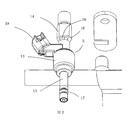
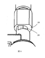
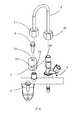
図1は本実施例に係る筒内噴射エンジンの上部を示し、燃料噴射システム装着部の斜視図である。図2は本実施例に係る燃料噴射システム装着部の縦断面図である。図3は燃料噴射装置の吊り下げ部材の取り付け形状を示す図である。図4は燃料噴射装置の吊下げ部の拡大図を示す図である。図5は燃料配管の要部の斜視図である。図6は燃料噴射システムの各パーツを展開した場合の斜視図である。
図1に示す内燃機関であるエンジン1は、自動車用の4サイクル直列4気筒ガソリンエンジンである。図2に示すようにエンジン1のシリンダヘッド2には燃料噴射システム3が装着されている。本実施例の燃料噴射システム3は、4本の燃料噴射装置5と燃料供給用の燃料配管4と各燃料噴射装置5を燃料配管4に接続する燃料パイプ6とをサブアッシィ化したものであり、2本のボルト8によってシリンダヘッド2に締結されている。
図2に示すように、シリンダヘッド2には、大径の噴射弁収容孔11と、噴射弁収容孔11より小径の噴射ノズル装着孔12とが形成されている。そして、噴射弁収容孔11には後述する燃料噴射装置5のボディ13が収容され、噴射ノズル装着孔12には後述する燃料噴射装置5の噴射ノズル15が組み込まれている。
図3に示すように、燃料噴射装置5は、円柱状のボディ13と、ボディ13の上部に設けられる配管接続部14と、配管接続部14に併設されたコネクタ部18とを備える。また燃料噴射装置5は、ボディ13の下面に設けられた噴射ノズル15と、ボディ13の上方に形成されたフランジ部16とを備える。さらに、噴射ノズル15の外周面にはエンジン本体(シリンダヘッド2)の装着孔12の内周面に圧接する弾性シール17が取り付けられている。この弾性シール17は装着孔12からの吹き抜け防止の役割を果たす。フランジ部16は軸方向及び径方向の位置を規制する規制手段であり、軸方向を規制する平面部19と、径方向を規制する側面部20を有している。前記燃料噴射装置の噴射ノズルの外周面に、
一方、燃料配管4は、燃料が流通する円筒状のパイプ本体21と、パイプ本体21の外周面に溶接、又は一体化された鋼板部品の保持ブラケット22とを備える。また燃料配管4は、パイプ本体21の上面に設けられた燃料配管接続部23と燃圧センサへの接続部25を主要構成要素としている。保持ブラケット22は、パイプ本体21の軸方向に沿うように配置され短形形状となっている。保持ブラケット22の一端側にボルト孔24が設けられている。燃圧センサの接続部25には、燃圧センサ10が接続される。
一方、燃料配管4は、燃料が流通する円筒状のパイプ本体21と、パイプ本体21の外周面に溶接、又は一体化された鋼板部品の保持ブラケット22とを備える。また燃料配管4は、パイプ本体21の上面に設けられた燃料配管接続部23と燃圧センサへの接続部25を主要構成要素としている。保持ブラケット22は、パイプ本体21の軸方向に沿うように配置され短形形状となっている。保持ブラケット22の一端側にボルト孔24が設けられている。燃圧センサの接続部25には、燃圧センサ10が接続される。
燃料パイプ6は略U字形状で形成され、その一端に燃料噴射装置5側の配管接続部14に締結されるナット26を備え、他端に燃料配管4側の燃料配管接続部23に締結されるナット27を備えている。吊り下げ部材7は、燃料噴射装置5の軸方向を規制する平面部28と、燃料噴射装置5の径方向を規制する平面部29が切りかかれた嵌合部30とを備えている。また長手方向において嵌合部30に対して反対側には、エンジンヘッドへ取り付ける際のボルト孔31が設けられている。
具体的には本実施例の燃料噴射システムは、その内部に燃料が流通する燃料供給配管4と、燃料供給配管4から燃料が供給される燃料パイプ6と、燃料パイプ6を通して燃料が供給されるとともに、その噴射ノズル15が内燃機関のエンジン1のシリンダヘッド2の噴射ノズル装着孔12に嵌挿される複数の燃料噴射装置5とを備える。そして、燃料噴射装置5は、シリンダヘッド2の噴射ノズル装着孔12の内周面に所定の圧接力をもって圧接する弾性シール17が外嵌している。また、燃料噴射装置5には、1つの係止部を有する保持フランジ(フランジ部16)が形成されている。また、燃料噴射装置5の係止部の1つに係合し、燃料噴射装置5とシリンダヘッド2の噴射ノズル装着孔12との軸方向を規制する軸方向変位規制手段28となる吊り下げ部材7が形成され、所定のクリアランス32をもって、燃料噴射装置5が噴射ノズル装着孔12に取り付けられる。さらに吊り下げ部材7はシリンダヘッド2に固定されるとともに、燃料供給配管4とは別体で配置される。
つまり本実施例においては、燃料供給配管4からの燃料が送られる燃料噴射装置5は、燃料噴射装置5のエンジン1の本体の側への荷重を受ける吊り下げ部材7により燃料供給配管4以外の固定部に取り付けられ、吊り下げ部材7は燃料供給配管4とは別体であることを特徴とするものである。つまり、この吊り下げ部材7は燃料噴射装置5をエンジン1の側に押し付けるものではなく、逆に燃料噴射装置5の荷重を受けて支持するための支持部材である。この吊り下げ部材7を燃料供給配管4とは別体に、かつ非接触で構成することで、燃料噴射装置5を燃料供給配管4とは別々にエンジン本体(シリンダヘッド2)に取り付けることができる。よって燃料供給配管4の配置とは無関係で吊り下げ部材7が配置できるため、レイアウトの自由度が得られる。また、吊り下げ部材7は簡単な構造であり、またこの取付のために燃料供給配管4に特別な構造を設ける必要が無いため、製造コストの低減を図りながら組立性を向上させることが可能となる。
なお、上記した燃料供給配管4以外の固定部とは本実施例においてはエンジン本体(エンジン1)、あるいはシリンダヘッド2であることが望ましい。また、吊り下げ部材7は固定部(エンジン1、シリンダヘッド2)にねじ止めにより固定される。これにより吊り下げ部材7を使って作業者が容易に固定部(エンジン1、シリンダヘッド2)に燃料噴射装置5を取り付けることが可能である。
また、本実施例では、吊り下げ部材7は燃料噴射装置5のフランジ部16に取り付けられて、燃料噴射装置5を固定させ、その吊り下げ部材7を固定部(エンジン1、シリンダヘッド2)に取り付ける。つまり、燃料配管4の組立とは別に組み立てられるため、燃料配管4の組立公差が燃料噴射装置5に影響を与えない。燃料噴射装置5を燃料配管4に組み付けてからエンジン1に組み付ける方法によると、燃料配管4の組立公差と、シリンダヘッド2と噴射ノズル装着孔12との位置公差と、の双方の公差の積み重ね分によっては、組み付ける際に燃料噴射装置をゆがませる虞があった。また、組み付け後、燃料噴射装置がゆがんでいると、燃料噴射装置の特性が変化したり、ゆがんだところが破損して燃料漏れにつながる虞があった。
これに対して本実施例によれば、燃料噴射装置5には、燃料配管4の組立公差が影響しないため、燃料噴射装置5をゆがませることなく使用できるため、燃料噴射装置5の噴射特性を劣化させることなく使用でき、燃料噴射装置5の破損を招く虞を低減し、信頼性を向上させることが可能となる。
また図7に示すとおり本実施例の燃料噴射システム3において、燃料噴射装置5と燃料パイプ6とは、燃料噴射装置5の金属シール受け面34と、燃料パイプ6の金属シール押付面35により、金属シールで接続されることで構成される。燃料パイプ6はある程度の弾性を有しており変形が可能である。
燃料噴射システム3の固定部(エンジン1、シリンダヘッド2)への組み付けの順番としては、まず吊り下げ部材7が取り付けられた燃料噴射装置7を固定部(エンジン1、シリンダヘッド2)の挿入孔(噴射弁収容孔11、噴射ノズル装着孔12)に挿入し、ボルト9を回転することで吊り下げ部材7を固定部(エンジン1、シリンダヘッド2)に固定する。次に燃料供給配管4を保持ブラケット22に形成されたボルト孔24に対してボルト8を回転することで、固定部(エンジン1、シリンダヘッド2)に固定する。
燃料噴射装置5側の配管接続部14と燃料配管4側の燃料配管接続部23とをそれぞれ燃料パイプ6で接続する。この状態ではまだナット26、27を締めていないので、燃料供給配管4と燃料噴射装置5とが燃料パイプ6により緩い状態で繋がっている。その後、ナット26、27を締めることにより、それぞれをシールすることができるとともに、燃料噴射装置5と燃料配管4とを締結することが可能である。なお、燃料配管4の組立公差やシリンダヘッド2と噴射ノズル装着孔12との位置公差があったとしても、これらの公差は燃料パイプ6により吸収されるので、燃料噴射装置5に対して公差を原因とする過剰な負荷がかかるのを抑制できる。
これにより、現在の燃圧より高い燃圧が要求された場合、たとえば燃料配管4の燃圧が30MPa以上の場合でも、燃料シールは可能になり、図1にあるような燃料噴射システムとして使用できるので、音を小さくする効果と、燃料噴射装置5をゆがめて特性悪化させることなく、エンジンでの使用が可能となる。
また図8、9に示すとおり、燃料噴射装置5は、吊り下げ部材7の長手方向における外周側から吊り下げ部材7に圧入により固定される。これにより、燃料噴射装置5の径方向の回転向きがばらつくことなく固定されるため、所望の燃料噴射装置5の噴霧形成が可能となる。また、燃料噴射装置5の圧入部36に樹脂を使うので、燃料噴射装置5の機械作動音の伝播を吊り下げ部材7に伝えるのを抑える効果もあり、エンジン1全体として、騒音低減効果が得られる。
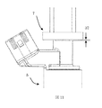
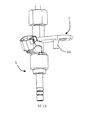
図10、11に示すとおり、燃料噴射装置5に吊り下げ部材7を取り付ける際、燃料噴射装置5の圧入部36と吊り下げ部材7とは、軸方向に所定の隙間37が形成されたことを特徴とする。これにより、吊り下げ部材7を燃料噴射装置5に取り付けることが容易になる。
燃料噴射装置5は図示していないが、その内部に、弁体と弁体と接触して上部に移動させる可動部と、可動部と対向して可動部の動きを規制する固定部とを有する。また内部に配置されたソレノイドに駆動電流が流れることで、固定部が励磁されてこれに可動部が吸引されることで弁体を押し上げ、これにより弁体がシート部から離れて開弁する。一方で、駆動電流がオフとなると弁体を閉弁方向に押し付ける強力なスプリングにより弁体がシート部に着座する。この場合、可動部が押し上げられて固定部に衝突する際に発生する音、また弁体がシート部に着座する際に発生する音が問題となる。
ここで燃料噴射装置5がエンジン1、又はシリンダヘッド2に固定された状態において、燃料噴射装置5が挿入孔に押し付けられて、軸方向において接触するように配置されることも考えられる。しかし、この場合、燃料噴射装置5と接触したエンジン1、又はシリンダヘッド2が拡声器として機能してしまい、上記したような燃料噴射装置5の内部音を拡張し、これによる騒音が特に問題となる。
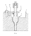
そこで本実施例においては、上位したように燃料噴射装置5が吊り下げ部材7により固定された状態において、吊り下げ部材7は、燃料噴射装置5と軸方向に所定の隙間37が形成されるように配置される。すなわち燃料噴射装置5の下端面は全域に渡ってエンジン1、又はシリンダヘッド2の装着孔11と軸方向に隙間が形成される。これにより、燃料噴射装置5の駆動部が発生させる機械的な音をシリンダヘッド2に伝えることがないため、燃料噴射装置5の音が広がらず、結果として、エンジン1全体の騒音低減効果を得ることができる。なお、吊り下げ部材7を介して固定部(エンジン1、シリンダヘッド2)に燃料噴射装置5の内部音が多少は伝わるが、燃料噴射装置5の内部音の発生源から遠くなることから、これによる騒音の問題は極めて小さい。
また図12に示すとおり、燃料噴射装置5が吊り下げ部材7により固定された状態において、燃料噴射装置5の圧入部と吊り下げ部材7との軸方向の隙間37は、燃料噴射装置5とシリンダヘッド2の噴射弁収容孔11との軸方向の隙間32より小さく形成されたことが望ましい。この隙間が逆の関係になっていると、燃料噴射装置5をシリンダヘッド2の噴射弁収容孔11に組み付けるときに、組み付けづらい虞があるが、これを抑制できる。
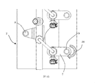
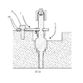
また図13、14、15に示すとおり、吊り下げ部材7に取り付け時のボルト9によるトルク38による回転を規制するため、ボルト9とは別に吊り下げ部材7に規制部33を設けたことが望ましい。これにより、吊り下げ部材7をシリンダヘッドに取り付ける、又は取り外す際の、ねじ止めのトルク39の働きで燃料噴射装置5をゆがませることがなくなり、燃料噴射装置5がゆがむことによる噴射特性への悪影響を低減可能である。
また図16に示すとおり、吊り下げ部材7の底部に弾性部材39をつけたことを特徴とする。つまり、吊り下げ部材7と固定部(エンジン1、シリンダヘッド2)との間に、又は吊り下げ部材7と燃料噴射装置5との間に、弾性部材が設けられることが騒音低減の観点から望ましい。これにより、燃料噴射装置5の振動が吊り下げ部材7を経由して、シリンダヘッド2に伝わりにくくなるため、全体として、エンジン1の音を抑えられる。
本発明は本実施例に限定されることなく幅広く実施することができる。例えば、本実施例では直列4気筒直噴エンジン用の燃料噴射システムに本発明を適用したものであるが、ディーゼルエンジンの燃料噴射システムに適用してもよいし、V型直噴エンジン用の燃料噴射アセンブリ等に適用してもよい。また、吊り下げ部材に形成する係止部や燃料噴射装置につけられる軸方向変位規制手段および径方向変位規制手段についても、上記実施例での例示に限るものではない。
1 エンジン(内燃機関)
2 シリンダヘッド
3 燃料噴射システム
4 燃料配管
5 燃料噴射装置
6 燃料パイプ
7 吊り下げ部材
8 ボルト(燃料配管取り付けボルト)
9 ボルト(吊り下げ部材取り付けボルト)
10 燃圧センサー
11 噴射弁収容孔
12 噴射ノズル装着孔
13 5のボディ
14 5の燃料噴射装置接続部
15 5の噴射ノズル
16 5のフランジ部
17 5の弾性シール部
18 5のコネクタ部
19 16の軸方向規制面
20 16の径方向規制面
21 4のパイプ本体
22 4の保持ブラケット
23 4の上部の燃料配管接続部
24 4のブラケット部のボルト孔
25 4の燃圧センサ接続部
26 6のフレアナット(燃料噴射装置側)
27 6のフレアナット(配管側)
28 7の平面部(軸方向規制面)
29 7の平面部(径方向規制面)
30 7の嵌合部
31 7のボルト孔
32噴射弁と噴射弁収容孔のクリアランス
33 7の回転規制部
34 5の金属シール受け面
35 6の金属シール押し面
36 5の圧入部
37 燃料噴射装置と吊り下げ部材のクリアランス
38 7を取り付けるときのトルク
39 弾性部材
Claims (19)
- 燃料供給配管からの燃料が送られる燃料噴射装置において、
前記燃料噴射装置は前記燃料噴射装置のエンジン本体の側への荷重を受ける吊り下げ部材により前記燃料供給配管以外の固定部に取り付けられ、
前記吊り下げ部材は前記燃料供給配管とは別体であることを特徴とする燃料噴射装置。 - 請求項1に記載の燃料噴射装置において、
前記固定部は前記エンジン本体であることを特徴とする燃料噴射装置。 - 請求項1に記載の燃料噴射装置において、
前記吊り下げ部材は前記固定部にねじ止めにより固定されることを特徴とする燃料噴射装置。 - 請求項1に記載の燃料噴射装置において、
前記燃料噴射装置は前記吊り下げ部材の長手方向における外周側から前記吊り下げ部材に圧入により固定されたことを特徴とする燃料噴射装置。 - 請求項1に記載の燃料噴射装置において、
前記燃料噴射装置が前記吊り下げ部材により固定された状態において、前記吊り下げ部材は、前記燃料噴射装置と軸方向に所定の隙間が形成されるように配置されることを特徴とする燃料噴射装置。 - 請求項1に記載の燃料噴射装置において、
前記燃料噴射装置が前記吊り下げ部材により固定された状態において、前記燃料噴射装置と前記吊り下げ部材との軸方向の隙間は、前記燃料噴射装置と前記エンジン本体との軸方向の隙間より小さくなるように配置されることを特徴とする燃料噴射装置。 - 請求項1に記載の燃料噴射装置において、
前記吊り下げ部材を前記固定部に固定する場合の前記吊り下げ部材の回転方向の動きを規制する規制部が設けられたことを特徴とする燃料噴射装置。 - 請求項1に記載の燃料噴射装置において、
前記吊り下げ部材と前記固定部との間に、又は前記吊り下げ部材と前記燃料噴射装置との間に、弾性部材が設けられたことを特徴とする燃料噴射装置。 - 請求項1に記載の燃料噴射装置において、
前記燃料供給配管と燃料パイプを介して接続され、
前記燃料パイプとは金属シール部を介して接続されることを特徴とする燃料噴射装置。 - 燃料供給配管と、前記燃料供給配管からの燃料が送られる燃料噴射装置と、を備えた燃料噴射システムにおいて、
前記燃料噴射装置は、前記燃料噴射装置のエンジン本体の側への荷重を受ける吊り下げ部材により前記燃料供給配管以外の固定部に取り付けられ、
前記吊り下げ部材は前記燃料供給配管とは別体であることを特徴とする燃料噴射システム。 - 請求項10に記載の燃料噴射システムにおいて、
前記燃料噴射装置の噴射ノズルの外周面に、前記エンジン本体の装着孔の内周面に圧接する弾性シールが取り付けられたことを特徴とする燃料噴射システム。 - 請求項10に記載の燃料噴射システムにおいて、
前記固定部は前記エンジン本体であることを特徴とする燃料噴射システム。 - 請求項10に記載の燃料噴射システムにおいて、
前記吊り下げ部材は前記燃料噴射装置の軸方向の変位を規制することを特徴とする燃料噴射システム。 - 請求項10に記載の燃料噴射システムにおいて、
前記燃料噴射装置は外周方向から前記吊り下げ部材に圧入により固定されたことを特徴とする燃料噴射システム。 - 請求項10に記載の燃料噴射システムにおいて、
前記燃料噴射装置が前記吊り下げ部材により固定された状態において、前記吊り下げ部材は、前記燃料噴射装置と軸方向に所定の隙間が形成されるように配置されることを特徴とする燃料噴射システム。 - 請求項10に記載の燃料噴射システムにおいて、
前記燃料噴射装置の下端面は全域に渡って前記エンジン本体の装着孔と軸方向に隙間が形成されることを特徴とする燃料噴射システム。 - 燃料供給配管からの燃料が送られる燃料噴射装置を吊り下げる吊り下げ部材において、
前記吊り下げ部材は、
前記燃料噴射装置のエンジン本体の側への荷重を受けるように構成されるとともに、
前記燃料供給配管以外の固定部に取り付けられ、さらに、
前記燃料供給配管とは別体で構成されることを特徴とする吊り下げ部材。 - 請求項17に記載の吊り下げ部材において、
前記固定部は前記エンジン本体であることを特徴とする吊り下げ部材。 - 請求項1に記載の吊り下げ部材において、
前記吊り下げ部材は、前記固定部にねじ止めにより固定されることを特徴とする吊り下げ部材。
Priority Applications (1)
| Application Number | Priority Date | Filing Date | Title |
|---|---|---|---|
| JP2017502011A JP6466562B2 (ja) | 2015-02-27 | 2016-02-01 | 燃料噴射装置、吊り下げ部材、及びこれらを備えた燃料噴射システム |
Applications Claiming Priority (2)
| Application Number | Priority Date | Filing Date | Title |
|---|---|---|---|
| JP2015037611 | 2015-02-27 | ||
| JP2015-037611 | 2015-02-27 |
Publications (1)
| Publication Number | Publication Date |
|---|---|
| WO2016136393A1 true WO2016136393A1 (ja) | 2016-09-01 |
Family
ID=56788310
Family Applications (1)
| Application Number | Title | Priority Date | Filing Date |
|---|---|---|---|
| PCT/JP2016/052852 Ceased WO2016136393A1 (ja) | 2015-02-27 | 2016-02-01 | 燃料噴射装置、吊り下げ部材、及びこれらを備えた燃料噴射システム |
Country Status (2)
| Country | Link |
|---|---|
| JP (1) | JP6466562B2 (ja) |
| WO (1) | WO2016136393A1 (ja) |
Citations (6)
| Publication number | Priority date | Publication date | Assignee | Title |
|---|---|---|---|---|
| JPS555463A (en) * | 1978-06-28 | 1980-01-16 | Hitachi Ltd | Fuel feeder |
| JPH1030522A (ja) * | 1996-07-17 | 1998-02-03 | Denso Corp | 燃料噴射装置 |
| JPH10141171A (ja) * | 1996-11-15 | 1998-05-26 | Zexel Corp | 燃料噴射弁の取付構造 |
| JP2002054534A (ja) * | 2000-08-10 | 2002-02-20 | Nissan Motor Co Ltd | エンジンの燃料噴射装置 |
| JP2009275692A (ja) * | 2008-03-28 | 2009-11-26 | Denso Corp | 燃圧センサ搭載構造、燃圧検出システム、燃料噴射装置、それに用いられる圧力検出装置及び蓄圧式燃料噴射装置システム |
| JP2010185359A (ja) * | 2009-02-12 | 2010-08-26 | Toyota Motor Corp | 内燃機関の燃料噴射装置 |
Family Cites Families (2)
| Publication number | Priority date | Publication date | Assignee | Title |
|---|---|---|---|---|
| JP2953035B2 (ja) * | 1990-11-02 | 1999-09-27 | 株式会社デンソー | 燃料噴射装置の搭載方法 |
| US7793639B2 (en) * | 2008-09-25 | 2010-09-14 | Hitachi, Ltd. | Apparatus for reducing the transmission for noise from the fuel rail in a direct injection engine |
-
2016
- 2016-02-01 WO PCT/JP2016/052852 patent/WO2016136393A1/ja not_active Ceased
- 2016-02-01 JP JP2017502011A patent/JP6466562B2/ja active Active
Patent Citations (6)
| Publication number | Priority date | Publication date | Assignee | Title |
|---|---|---|---|---|
| JPS555463A (en) * | 1978-06-28 | 1980-01-16 | Hitachi Ltd | Fuel feeder |
| JPH1030522A (ja) * | 1996-07-17 | 1998-02-03 | Denso Corp | 燃料噴射装置 |
| JPH10141171A (ja) * | 1996-11-15 | 1998-05-26 | Zexel Corp | 燃料噴射弁の取付構造 |
| JP2002054534A (ja) * | 2000-08-10 | 2002-02-20 | Nissan Motor Co Ltd | エンジンの燃料噴射装置 |
| JP2009275692A (ja) * | 2008-03-28 | 2009-11-26 | Denso Corp | 燃圧センサ搭載構造、燃圧検出システム、燃料噴射装置、それに用いられる圧力検出装置及び蓄圧式燃料噴射装置システム |
| JP2010185359A (ja) * | 2009-02-12 | 2010-08-26 | Toyota Motor Corp | 内燃機関の燃料噴射装置 |
Also Published As
| Publication number | Publication date |
|---|---|
| JPWO2016136393A1 (ja) | 2017-09-07 |
| JP6466562B2 (ja) | 2019-02-06 |
Similar Documents
| Publication | Publication Date | Title |
|---|---|---|
| US10197033B2 (en) | Fuel-injection device | |
| US10648439B2 (en) | System having a fuel distributor and multiple fuel injectors | |
| US9347411B2 (en) | Decoupling element for a fuel injection device | |
| JP5426899B2 (ja) | 直噴内燃エンジンにおける燃料レールの振動伝播低減装置 | |
| US8757128B2 (en) | Decoupling element for a fuel injection device | |
| US9920728B2 (en) | Fuel injection system comprising a fuel-guiding component, a fuel injection valve and a mounting | |
| US20100300409A1 (en) | Fuel system for a direct injection internal combustion engine | |
| US10184437B2 (en) | Arrangement with a fuel distributor and multiple fuel injection valves | |
| US10641224B2 (en) | Decoupling element for a fuel-injection device | |
| US20140026401A1 (en) | Fuel rail mount | |
| CN104254684B (zh) | 具有燃料分配器和多个燃料喷射阀的装置 | |
| CN101624953B (zh) | 用于直喷式内燃机的高压喷射系统 | |
| JP5448872B2 (ja) | 直噴内燃エンジンの燃料システム | |
| CN104024625B (zh) | 用于燃料喷射装置的脱耦元件 | |
| CN104471234B (zh) | 用于燃料喷射装置的多件式隔离元件 | |
| JP6466562B2 (ja) | 燃料噴射装置、吊り下げ部材、及びこれらを備えた燃料噴射システム | |
| CN110959069B (zh) | 燃料喷射阀 | |
| EP2935856B1 (en) | Arrangement for supplying fuel to an engine | |
| JP5811760B2 (ja) | 燃料ポンプの取付構造 | |
| JP4542542B2 (ja) | 燃料噴射モジュール | |
| JP7180573B2 (ja) | インジェクタ取付構造 | |
| JP6536366B2 (ja) | 燃料噴射装置 | |
| JP7464809B2 (ja) | 燃料噴射システム | |
| KR100384013B1 (ko) | 자동차의 연료파이프 고정용 브라켓 | |
| JP2019190345A (ja) | シリンダヘッドカバー |
Legal Events
| Date | Code | Title | Description |
|---|---|---|---|
| 121 | Ep: the epo has been informed by wipo that ep was designated in this application |
Ref document number: 16755143 Country of ref document: EP Kind code of ref document: A1 |
|
| ENP | Entry into the national phase |
Ref document number: 2017502011 Country of ref document: JP Kind code of ref document: A |
|
| NENP | Non-entry into the national phase |
Ref country code: DE |
|
| 122 | Ep: pct application non-entry in european phase |
Ref document number: 16755143 Country of ref document: EP Kind code of ref document: A1 |