WO2016136309A1 - 電子筆記処理プログラム及び記録媒体 - Google Patents
電子筆記処理プログラム及び記録媒体 Download PDFInfo
- Publication number
- WO2016136309A1 WO2016136309A1 PCT/JP2016/050830 JP2016050830W WO2016136309A1 WO 2016136309 A1 WO2016136309 A1 WO 2016136309A1 JP 2016050830 W JP2016050830 W JP 2016050830W WO 2016136309 A1 WO2016136309 A1 WO 2016136309A1
- Authority
- WO
- WIPO (PCT)
- Prior art keywords
- character
- data
- stroke data
- stroke
- processing program
- Prior art date
- Legal status (The legal status is an assumption and is not a legal conclusion. Google has not performed a legal analysis and makes no representation as to the accuracy of the status listed.)
- Ceased
Links
Images








Classifications
-
- G—PHYSICS
- G06—COMPUTING OR CALCULATING; COUNTING
- G06F—ELECTRIC DIGITAL DATA PROCESSING
- G06F3/00—Input arrangements for transferring data to be processed into a form capable of being handled by the computer; Output arrangements for transferring data from processing unit to output unit, e.g. interface arrangements
- G06F3/01—Input arrangements or combined input and output arrangements for interaction between user and computer
- G06F3/03—Arrangements for converting the position or the displacement of a member into a coded form
- G06F3/041—Digitisers, e.g. for touch screens or touch pads, characterised by the transducing means
-
- G—PHYSICS
- G06—COMPUTING OR CALCULATING; COUNTING
- G06V—IMAGE OR VIDEO RECOGNITION OR UNDERSTANDING
- G06V10/00—Arrangements for image or video recognition or understanding
- G06V10/98—Detection or correction of errors, e.g. by rescanning the pattern or by human intervention; Evaluation of the quality of the acquired patterns
Definitions
- the present invention relates to an electronic writing processing program for converting written content by an operator into electronic data, and a recording medium on which the program is recorded.
- Patent Document 1 A technique for converting electronic data written by an operator using a writing instrument is already known (see, for example, Patent Document 1).
- this conventional technique when an operator appropriately writes a plurality of characters in a desired order in various places of a predetermined area (for example, one page) of a writing medium (paper medium) with a writing instrument (electronic pen).
- the stroke data including the position data of the writing instrument that moves during the above description is generated.
- the generated stroke data is converted into image data, transmitted to the server, and stored.
- the generated stroke data is converted into image data as it is.
- Character string data multiple characters
- Text data of the character may be generated.
- An object of the present invention is to provide an electronic writing processing program and a recording medium on which the electronic writing processing program is recorded, which can improve the convenience of the operator by clarifying the transition of the description contents on the writing medium.
- the present invention transmits a plurality of position data of the writing tool accompanying the movement of the writing tool with respect to the writing medium, and transmits stroke data corresponding to the writing of characters on the writing medium by the writing tool by communication.
- Character string data including a plurality of corresponding character data by performing character recognition processing on the stroke data received from the electronic writing device to the arithmetic means of the operation terminal connected to the electronic writing device so as to be capable of transmitting and receiving information
- a first stroke data related to any first character data included in the plurality of character data is located in the character string data immediately before the first character data.
- a first determination is made as to whether or not the second stroke data relating to the character data has been generated within a predetermined waiting time after the second stroke data is generated.
- the operation terminal for executing the present invention is connected to the electronic writing device so that information can be transmitted and received.
- an operator appropriately writes a plurality of characters in a desired order in various places of a predetermined area (for example, one page) of a writing medium with a writing instrument
- the writing instrument moves at the time of the above description in the electronic writing apparatus.
- Stroke data including the position data is generated and transmitted to the operation terminal.
- the character string data generation procedure performs an appropriate character recognition process on the stroke data received from the electronic writing device, and applies to the writing medium. Character string data including a plurality of character data corresponding to the description is generated.
- first characters whose description timings are far from each other are incorporated into separate groups (not handled as a unit).
- generation of stroke data (first stroke data) of the character data (first character data) for each of a plurality of character data constituting the character string data is performed in the character string.
- stroke data (second stroke data) of the character data (second character data) corresponding to the immediately preceding description, it is determined whether or not it was made within a predetermined time (standby time). If it is outside the predetermined time, the first character data and the second character data are incorporated into separate character groups (without being subject to determination in a second determination procedure described later).
- the first stroke data of the first character data is generated within a predetermined time from the generation of the second stroke data of the second character data
- the first stroke data and the second stroke are further generated. It is determined whether the data is in a relatively close state.
- a predetermined region (first virtual region) virtually including the first stroke data and a predetermined region (first virtual region) including the second stroke data It is determined whether or not there is an overlapping portion in the second virtual area. If there is an overlapping portion, the first stroke data and the second stroke data are sufficiently close to each other, so that they are considered to be handled in an integrated manner.
- the character group recognition procedure the first character data And the second character data are recognized in the form of being incorporated into one common character group. When there is no overlapping portion, it is considered that the first stroke data and the second stroke data are not close to each other and should be handled separately, and the first character data and the second character data are separated in the character group recognition procedure. Are recognized by being incorporated into each character group.
- a plurality of character data is collectively processed as a character group for each data in which each stroke data is relatively close in time and relatively close in position.
- the handwriting input system 1 includes an electronic writing device 2, a so-called electromagnetic induction type electronic pen 3 (corresponding to a writing instrument), and an operation terminal 400.
- the operation terminal 400 is connected to the electronic writing apparatus 2 via wireless communication or wired communication, and transmits / receives information to / from the electronic writing apparatus 2.
- the electronic writing device 2 has a thin rectangular parallelepiped shape that is long in the vertical direction in plan view.
- a small display 21 capable of displaying various information is provided in the upper right part of the electronic writing apparatus 2.
- an input unit 22 for an operator to operate the electronic writing device 2 is provided on the left side of the display 21, an input unit 22 for an operator to operate the electronic writing device 2 is provided.
- a concave-shaped placing part 24 is provided so as to occupy most of the front side of the electronic writing apparatus 2.
- the placement unit 24 is provided with a coordinate detection unit 25 so as to be in the same range as the placement unit 24.
- the coordinate detection unit 25 detects coordinate data representing the position of the electronic pen 3 (corresponding to position data.
- the upper left portion of the placement unit 24 is the origin (0, 0), details will be described later).
- a paper medium 70 (corresponding to a writing medium; see FIG. 5 described later) is placed on the placement unit 24. At this time, the placement unit 24 holds the paper medium 70 in a posture in which the upper left corner of the paper medium 70 matches the origin.
- the electronic pen 3 includes a metal core 37, a detection switch 33, a button-type battery 34, a coil 35, and a substrate 36.
- the core 37 is provided inside the tip of the electronic pen 3 and includes a pen tip 31 that protrudes to the outside and an ink storage portion 32. Ink is stored in the ink storage portion 32, and the ink is supplied to the pen tip 31. As a result, the operator can write (fill in) desired characters, graphic images, etc. on the paper medium 70 using the electronic pen 3.
- the direction in which the pen tip 31 is provided is referred to as the front end direction
- the direction opposite to the front end direction is referred to as the rear end direction.
- the substrate 36 is provided in the rear end direction of the core 37.
- the detection switch 33 is mounted on the tip of the substrate 36.
- the detection switch 33 is electrically connected to the coil 35 via a wiring on the substrate 36.
- the coil 35 is wound around the core 37 at the tip end inside the electronic pen 3.
- the battery 34 is provided in the rear end direction of the substrate 36.
- the battery 34 is connected to the substrate 36, the negative electrode is electrically connected to the coil 35 via the wiring on the substrate 36, and the positive electrode is connected to the detection switch 33 via the wiring on the substrate 36. Is electrically connected.
- the core 37 is always urged in the distal direction by an elastic member (not shown).
- the core 37 is slightly retracted and enters the inside of the electronic pen 3 against the urging force of the elastic member by the pressing force when the operator writes characters, images and the like on the paper medium 70.
- the rear end of the lead 37 presses the detection switch 33, and the detection switch 33 is turned on.
- the battery 34 and the coil 35 are electrically connected, current flows from the battery 34 toward the coil 35, and a current flows through the coil 35, thereby generating a magnetic field.
- the coordinate detection unit 25 detects the magnetic field generated from the coil 35 as described above based on electromagnetic induction. Since this detection is sufficient by a known method, detailed description is omitted. Based on the detection result of the coordinate detection unit 25, the CPU 201 described later performs discrete operation of the electronic pen 3 corresponding to the movement of the electronic pen 3 when the operator performs a writing operation on the paper medium 70 using the electronic pen 3. A plurality of the above coordinate data are obtained.
- the value of the X coordinate represents the horizontal position of the placement unit 24 (coordinate detection unit 25)
- the value of the Y coordinate represents the vertical position of the placement unit 24 (coordinate detection unit 25).
- the CPU 201 uses the electronic pen 3 and stroke data corresponding to characters, images, and the like written on the paper medium 70 by the operator (details will be described later). ) Is generated.
- the electronic writing apparatus 2 includes a CPU 201 that controls the electronic writing apparatus 2, a ROM 202, a RAM 203 that temporarily stores various data, a flash memory 204, and the input unit 22.
- the ROM 202, the RAM 203, and the flash memory 204 are electrically connected to the CPU 201.
- the ROM 202 includes a program storage area 2021 and an image data storage area 2023.
- the program storage area 2021 stores various programs including a coordinate data processing program (a program for executing each procedure shown in the flow of FIG. 11 described later) executed by the CPU 201.
- image data storage area 2023 for example, image data corresponding to the format information of the paper medium 70 is stored.
- the flash memory 204 includes a coordinate data storage area 2041.
- the coordinate data storage area 2041 sequentially stores a plurality of coordinate data acquired by the CPU 201 based on the detection result of the coordinate detection unit 25 as described above.
- the RAM 203 temporarily stores stroke data generated based on a plurality of coordinate data stored in the coordinate data storage area 2041.
- the input unit 22 and the drive circuits 206 and 209 are electrically connected to the CPU 201.
- the drive circuits 206 and 209 are electronic circuits for driving the display 21 and the coordinate detection unit 25, respectively.
- the stroke data is a pen position data string composed of a plurality of coordinate data acquired by the CPU 201 based on the detection result of the coordinate detection unit 25.
- FIGS. 3A and 3B show examples of two stroke data “a” and “b”.
- the first stroke data “a” is data representing the locus of the one-stroke portion from the beginning to the end of writing of the character “a” by the electronic pen 3.
- the second stroke data “b” is data representing the trajectory of the one-stroke portion from the beginning of writing to the end of writing of the character “b” by the electronic pen 3, and the pen position numbers T12, T13 are arranged in time series.
- the CPU 201 generates stroke data corresponding to characters, icons, and the like described on the paper medium 70 by the operator using the electronic pen 3 based on a plurality of coordinate data based on the detection result of the coordinate detection unit 25. To do.
- the stroke data generated by the electronic writing device 2 is transmitted to the operation terminal 400 via the communication control unit 207.
- the operation terminal 400 includes a CPU 41 (corresponding to calculation means), a memory 42 as a recording medium, an operation unit 43 such as operation buttons, a display unit 44 (corresponding to display means), a communication control unit 45, and the like. Yes.
- the CPU 41 executes various programs including an electronic writing processing program according to the present embodiment (a program for executing a procedure shown in FIG. 12 described later) stored in advance in the memory 42, and the entire operation terminal 400. To control.
- the CPU 41 performs character recognition processing on the stroke data transmitted from the electronic writing device 2 by executing the electronic writing processing program, and generates character string data including a plurality of recognized character data.
- the memory 42 is configured by a nonvolatile memory such as an electrically erasable programmable read-only memory (EEPROM) that can add and delete stored contents.
- EEPROM electrically erasable programmable read-only memory
- the memory 42 stores various programs including the electronic writing processing program executed by the CPU 41.
- the operation unit 43 includes operation buttons and operation keys for performing various operations of the operation terminal 400. For example, when the operation terminal 400 is turned on by operating the operation unit 43, the execution of the electronic writing processing program is disclosed.
- the display unit 44 has a predetermined display function, and displays the character string data generated from the stroke data by appropriately grouping (details will be described later).
- the communication control unit 45 is connected to the electronic writing device 2 via wireless communication (or wired communication), and controls information communication.
- the stroke data transmitted from the electronic writing device 2 is received by the operation terminal 400 via the communication control unit 45.
- FIG. 5 shows an example of the case where the operator enters a description of desired characters or images using the electronic pen 3 on the paper medium 70 on the placement section 24.
- a group of character strings T of “system is still sound that is new” written horizontally as a description R of a desired character, icon, or the like is written on the paper medium 70 in two upper and lower stages.
- a storage box 72 for transmitting a plurality of coordinate data stored in the coordinate data storage area 2041 to the operation terminal 400 is provided at an appropriate location (in the lower right corner in this example) of the paper medium 70. It has been.
- the stroke data “s” “y” “s” “t” “e” “m” “i” “s” are relatively close to each other, and “s” “ The stroke data of “t” “i” “l” “l” are relatively close to each other, and “s” “o” “u” “n” “d” “t” “h” “a” “t” “i”
- the stroke data of “s”, “n”, “e”, and “w” are relatively close to each other, and the stroke data of “s” of “is” and “s” of “still” are relatively distant from each other.
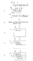
- FIGS. 7A to 7E Details of the grouping method will be described with reference to FIGS. First, details of the grouping shown in FIG. 6B are shown in FIGS. 7A to 7E.
- FIG. 7A “s” “y” “s” “t” “e” “m” “i” “s” “st” “i” “l” that constitutes “systemsound soundthathnew” of the character string T.
- character stroke data W (consisting of a plurality of coordinate data, hereinafter referred to as “character stroke data W” as appropriate) is generated as data relatively close in time to the adjacent character stroke data W.
- “relatively close in time” means that a predetermined waiting time after the character stroke data W of any one character in the character string T is generated immediately before another character stroke data W positioned immediately before the character stroke data W is generated.
- the first coordinate data of the one character stroke data W (for example, the data of the pen position number T12 shown in FIG. 3B) is another character stroke positioned immediately before it.
- the last coordinate data of the data W (for example, data of the pen position number T11 shown in FIG. 3B) may be generated within the standby time.
- the waiting time can be calculated from time data (not shown) when the electronic pen 3 is associated with each coordinate data constituting the character stroke data W.
- the character data “y” (not shown) generated by character recognition of the subsequent character stroke data W is changed to the previous character stroke data W.
- the character data “s” (not shown) generated by the recognition is incorporated into one common character group (see FIGS. 7B to 7E described later). That is, the character group “sy” is formed at this time.
- the character group “sy” “S” is further incorporated into “” to form the character group “sys”.
- the virtual area C of the character stroke data W for each of “t”, “e”, “m”, “i”, and “s” overlaps with the virtual area C of the character stroke data W of the immediately preceding character.
- the data is further incorporated sequentially to form the character group “systemis”.
- the virtual area C of the character stroke data W of “s” after “is” does not overlap with the virtual area C of the character stroke data W of “s” of “s” immediately before “is”.
- the character data of “s” after is not incorporated into the character group “systemis” but is incorporated into another character group alone.
- the character group “still” is formed by sequentially incorporating the character data “t”, “i”, “l”, and “l” into the character group common to the character data “s” by the same method as described above. Is done.
- the virtual region C of the character stroke data W of “s” after “stil” does not overlap with the virtual region C of the character stroke data W of “l” immediately before, and is different from the virtual region C by itself as described above.
- the character data “o” “u” “n” “d” “t” “h” “a” “t” “i” “s” “n” is incorporated into one character group.
- “E” and “w” are sequentially incorporated in the character group common to the character data “s”, thereby forming the character group “soundththisnew”.
- the character string T of “systemstilthsnewsnew” is character-recognized and converted into text data, and then using the dictionary file as described above, as shown in FIG. 7B, the character group “systemis is ”, Character group“ still ”, and character group“ sound that is new ”.
- the character groups “system is”, “still”, and “sound that is new” are sequentially displayed in time series in the display unit 44 (not all of them are displayed in a list). That is, first, as shown in FIG. 7C, the display unit 44 is in a state where the character group G of “system is” is displayed, and at an appropriate timing thereafter, as shown in FIG. 7D. , The character group G of “system is” and the character group G of “still” are displayed (that is, a state where the character group “still” is added and displayed). 7 (e), the character group G of “system is”, the character group G of “still”, and the character group F of “sound that is new” are displayed (that is, the character group “sound that is new”). "Is added and displayed).
- 8A as in FIG. 7, “s” “y” “s” “t” “e” “m” “i” “s” “st” “i” “l” “l” “s” “O” “u” “n” “d” “t” “h” “a” “t” “i” “s” “n” “e” “w” are adjacent to each other. It is generated as data that is relatively close in time to the character stroke data W. As in the above case, the first character group “systemis” is first formed.
- the virtual region C of the character stroke data W of “s” after “is” does not overlap with the virtual region C of the character stroke data W of “s” of “s” immediately before, and the subsequent “t”.
- the virtual region C of the character stroke data W is overlapped with the virtual region C of the character stroke data W of the preceding “s” and is incorporated into a character group common to “s”.
- “L” “l” “s” “o” “u” “n” “d” are sequentially incorporated in the character group common to the character data “s”, thereby forming the character group “stillsound”.
- the virtual area C of the character stroke data W of “t” after “sound” does not overlap with the virtual area C of the character stroke data W of “d” immediately before, and the character “h” thereafter.
- the virtual area C of the stroke data W overlaps with the virtual area C of the character stroke data W of the previous “t” and is incorporated into the character group common to “t”, and thereafter the character data “a”, “
- the character group “thatisnew” is formed by incorporating t, “i”, “s”, “n”, “e”, and “w” into the character group common to the character data “t”.
- the character groups “system is”, “still sound”, and “that is new” are sequentially displayed in time series on the display unit 44 as described above. That is, first, as shown in FIG. 8C, the display unit 44 is in a state where the character group G of “system is” is displayed, and at an appropriate timing thereafter, as shown in FIG. 8D. , The character group G of “system is” and the character group G of “still sound” are displayed (that is, the character group “still sound” is additionally displayed), and at an appropriate timing thereafter. As shown in FIG. 8E, the character group G of “system is”, the character group G of “still sound”, and the character group F of “that is new” are displayed (that is, the character group “that is”. “new” is additionally displayed).
- the character stroke data W is relatively similar in time to the adjacent character stroke data W, as described above. It is generated as close data.
- the virtual region C of the character stroke data W of “value” overlaps the virtual region C of the preceding “large” character stroke data W, so that “value” is added to the character group “maximum”. Further, the character group “maximum value” is formed. Further, since the virtual region C of the character stroke data W of “to” overlaps with the virtual region C of the character stroke data W of the previous “value”, the character data of “to” is added to the character group “maximum value”. Are further incorporated to form the character group “Maximum”.
- the character data of “NA” is the character group “maximum value”. Is not incorporated into a single character group. Thereafter, the character data “t”, “te”, “i” and “ru” are sequentially incorporated into the character group common to the character data “na” in the same manner as described above, so that the character group “is”. Is formed.
- the virtual region C of the character stroke data W of “to” does not overlap with the virtual region C of the character stroke data W of the previous “ru”, and is incorporated into another single character group as described above.
- the character data “to”, “ko”, “ro”, “ga”, “near”, “year”, and “ha” are sequentially incorporated into the character group “to” in common with the character data “to”.
- the character group “but in recent years” is formed.
- the character string T “where the maximum value is in recent years” is character-recognized and converted into text data, and then the character group “maximum value”, The character group “Naru” and the character group “Tokoro in recent years” are grouped into three groups.
- the dictionary file does not necessarily have to be used.
- the character groups “maximum value”, “is”, and “in recent years” are sequentially displayed in time series on the display unit 44 as described above. That is, first, as shown in FIG. 9C, the display unit 44 is in a state in which the character group G of “maximum value” is displayed, and at an appropriate timing thereafter, as shown in FIG. 9D. In addition, a character group G of “maximum value” and a character group G of “being” are displayed (that is, a state in which the character group “being” is additionally displayed), and thereafter At an appropriate timing, as shown in FIG. 9E, a character group G of “maximum value”, a character group G of “being”, and a character group F of “but recently” are displayed ( In other words, the character group “but in recent years” is additionally displayed).
- FIGS. 10 (a) to 10 (e) another example of grouping Japanese character string data is shown in FIGS. 10 (a) to 10 (e).
- FIG. 10A as in FIG. 9 above, “most” “large” “value” “to” “na” “t” “te” “i” “ru” “to” “ko” “ro” “The character stroke data W of "", “near”, “year”, and “ha” are generated as data that is relatively close in time to the adjacent character stroke data W.
- the first character group “maximum value” is first formed.
- the virtual area C of the character stroke data W of “NA” does not overlap with the virtual area C of the character stroke data W of the preceding “TO”, and the virtual area C of the character stroke data W of “tsu” after that is It overlaps with the virtual area C of the preceding character stroke data W of “NA” and is incorporated into the character group common to “NA”, and thereafter the character data “TE” “I” “RU” “TO”. “Ko”, “ro”, and “ga” are sequentially incorporated into the character group common to the character data “na”, thereby forming the character group “where is”.
- the virtual region C of the “near” character stroke data W does not overlap with the virtual region C of the character stroke data W immediately before the “ga”, and the virtual region of the character stroke data W of the subsequent “year” C overlaps with the virtual region C of the immediately preceding “near” character stroke data W and is incorporated into a character group common to “near”.
- the character data “ha” becomes the character data “near”.
- the character group “in recent years” is formed.
- the character string T “where the maximum value is in recent years” is character-recognized and converted into text data, and then, as shown in FIG. There are three groups: “maximum value”, character group “where is”, and character group “in recent years”.
- the character groups “maximum value”, “where it is” and “in recent years” are sequentially displayed in time series on the display unit 44 as described above. That is, first, as shown in FIG. 10C, the display unit 44 is in a state where the character group G of “maximum value” is displayed, and at an appropriate timing thereafter, as shown in FIG. In addition, the character group G of “maximum value” and the character group G of “where is” are displayed (that is, the state where the character group “is” is added and displayed), and At an appropriate timing thereafter, as shown in FIG. 10E, a character group G of “Maximum value”, a character group G of “Narutoga”, and a character group F of “in recent years” are displayed. A state (that is, a state in which the character group “in recent years” is additionally displayed) is displayed.
- step S10 the CPU 201 acquires a plurality of coordinate data of the electronic pen 3 as described above based on the detection result of the coordinate detection unit 25 when the operator writes on the paper medium 70.
- the acquired coordinate data is sequentially stored in the coordinate data storage area 2041.
- step S20 the CPU 201 determines whether or not an instruction to save the coordinate data acquired in step S10 has been issued (a check mark is entered in the save box 72). Until the operator enters a check mark in the storage box 72 provided on the paper medium 70, the determination in step S20 is not satisfied (S20: NO), and the same procedure is repeated by returning to step S10. When the check mark is entered, the determination in step S20 is satisfied (S20: YES), and the process proceeds to step S30.
- step S30 the CPU 201 generates stroke data corresponding to the description R on the paper medium 70 by the operator based on the plurality of coordinate data stored in the coordinate data storage area 2041 in step S10.
- the generated stroke data is temporarily stored in the RAM 203.
- step S40 the CPU 201 transmits the stroke data stored in the RAM 203 in step S30 to the operation terminal 400 via the communication control unit 207. Thereafter, this flow is terminated.
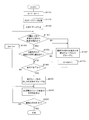
- FIG. 12 shows a flow representing a processing procedure executed by the CPU 41 of the operation terminal 400 in order to realize the grouping method shown in FIG. 7 and FIG.
- the flow shown in FIG. 12 is started when the operation terminal 400 is powered on, for example.
- step S110 ends the process proceeds to step S120.
- step S120 the CPU 41 detects the stroke data transmitted from the electronic writing apparatus 2 in step S40 of FIG. 11 (“s” “y” “s” “t” “e” “m” in the example of FIG. 7 FIG. “I” “s” “s” “t” “i” “l” “l” “s” “o” “u” “n” “d” “t” “h” “a” “t” “i”
- the character stroke data W) “s” “n” “e” “w” is received and acquired via the communication control unit 45.
- step S120 ends, the process proceeds to step S130.
- step S130 the CPU 41 performs character recognition processing on the stroke data acquired in step S120 by a known method, and corresponding character string data ("s" “y” “s” in the example of FIG. 7 FIG. 8).
- This step S130 corresponds to the character string data generation procedure described in each claim.
- step S140 the CPU 41 generates the Nth character stroke data W of the character string data generated in step S130 within a predetermined time (0.5 seconds in the above example) from the immediately preceding character stroke data W. It is determined whether or not.
- the character stroke data W of “y” related to the second character data “y” is the first character data “s” (first It is determined whether or not it was generated within the predetermined time from the character stroke data W of “s” relating to 2 character data).
- step S140 It is determined whether it was generated within. If generated within the predetermined time, the determination in step S140 is satisfied (S140: YES), and the process proceeds to step S150. If it is not generated within the predetermined time, the determination in step S140 is not satisfied (S140: NO), and the process proceeds to step S160 described later. This step S140 corresponds to the first determination procedure.
- step S150 corresponds to the second determination procedure described in each claim.
- step S160 transferred from step S140 and step S150, the CPU 41 groups all character data up to the immediately preceding character data into one character group G as the Mth group.
- the first character data “s” immediately before the second character data “y” forms the character group G independently.
- the above dictionary file may be referred to.
- step S170 the CPU 41 increases the order variable M of the character group G by one.
- step S170 ends the process proceeds to step S180.
- step S180 the CPU 41 determines whether or not the grouping in step S160 has been completed for all character data included in the character string data generated in step S130. If the grouping in step S160 is not completed for all character data, the determination in step S180 is not satisfied (S180: NO), and the process proceeds to step S190. When the grouping is completed for all the character data, the determination in step S180 is satisfied (S180: YES), and the process proceeds to step S200 described later.
- the character group “systemis” is formed by “s” “y” “s” “t” “e” “m” “i” “s” (in this example, “system is” is further obtained by using a dictionary file). Become).
- step S140 After that, through steps S170 and S180, the procedures of step S140 ⁇ step S150 ⁇ step S180 ⁇ step S190 ⁇ step S140... Are repeated for “t”, “i”, “l”, and “l” in the same manner as described above. Since the determination in step S150 is not satisfied after the step S140 for the character data “s”, the character group “still” with the character data “s” “t” “i” “l” “l” up to that point in step S160. Is formed. Thereafter, after steps S170 and S180, “o” “u” “n” “d” “t” “h” “a” “t” “i” “s” “n” “ Steps S140, S150, S180, S190, S140,... are repeated for e ”and“ w ”. Then, the determination in step S180 is satisfied for the character data “w”, and the process proceeds to step S200.
- step S200 the CPU 41 groups all remaining ungrouped character data in the character string data.
- the remaining character data “s” “o” “u” “n” “d” “t” “h” “a” “t” “i” “s” “N” “e” “w” forms a character group “soundthatisnew” (in this example, a dictionary file is used to make “sound that is new”).
- step S210 ends, the process proceeds to step S220.
- This step S210 corresponds to the character group display procedure described in each claim.
- step S220 the CPU 41 determines whether or not the character string of the character group G in the last order has been displayed. If it is not the last character group G, the determination in step S220 is not satisfied (S220: NO), and the same procedure is repeated by returning to step S210.
- the character string displayed on the display unit 44 is the character string of the last character group G
- Step S150 it is determined whether or not the two character stroke data W are relatively close to each other. Specifically, it is determined whether or not there is an overlapping portion between the virtual regions C that are assumed to include the character stroke data W (see step S150). If there is an overlapping portion, it is considered that these two character stroke data W are sufficiently close to each other and should be handled integrally, and are recognized in a form incorporated into one common character group G ( Step S150 ⁇ Step S180 ⁇ Step S190 ⁇ Step S140 ⁇ Refer to the flow of Step S160). If there is no overlapping portion, the two character stroke data W are not close to each other and are considered to be handled separately, and are recognized as being incorporated in different character groups G (step S150 ⁇ step S160). See the flow).
- a plurality of character data included in character string data generated by character recognition of stroke data are compared with each other in terms of generation of stroke data relatively close in time and position.
- Each target data is processed collectively as a character group G.
- the first coordinate data of one character stroke data W is the last coordinate data of another character stroke data W positioned immediately before it. It is determined whether or not it has been generated within the waiting time after generation (see step S140). Thereby, it can be determined more accurately whether the writing timings of the corresponding characters are close or far from each other for two adjacent character stroke data W.
- the virtual area C is an area within a substantially circular encircling line surrounding the character stroke data W.
- a plurality of character groups G recognized by the determination of each character data included in the character string data are sequentially displayed in time series on the display unit 44 of the operation terminal 400 (FIG. 7).
- FIG. 7 a plurality of character groups G recognized by the determination of each character data included in the character string data are sequentially displayed in time series on the display unit 44 of the operation terminal 400 (FIG. 7).
- each of the virtual regions C virtualized for two adjacent stroke data is an area within a substantially circular encircling line.
- it is not limited to this. Such a modification will be described with reference to FIGS.
- FIG. 13 (a) corresponds to FIG. 7 (a) and FIG. 8 (a).
- the last character of “s” In this example, in each character stroke data W of “s”, “t”, “r”, “e”, “e”, “t”, and “s” constituting the character string T of “streets”, the last character of “s”
- the immediately preceding character data “s” “t” “r” “e” “e” “t” ” Forms a character group“ street ”.
- the virtual region C related to the seventh “s” character stroke data to be determined is substantially circular as in the above-described embodiment, and the sixth “t” immediately before the overlapping target is “t”.
- the character stroke data “” is long in the arrangement direction of the character stroke data W of the above six “s” “t” “r” “e” “e” “t”.
- the sixth “t” character Even if the stroke data W and the seventh “s” character stroke data W are somewhat separated, the virtual area C ′ and the virtual area C overlap.
- the seventh “s” character data is determined to be character data to be incorporated into the “street” character group G to which the sixth “t” character data belongs, and one character “streets” is determined. Grouped as character group G.
- the above-described processing determination of whether or not to incorporate into the existing character group
- the immediately preceding character data “Ground” “Method” The character group “local small and medium society” is formed by “no”, “medium”, “small”, and “meeting”.
- the virtual region C related to the character stroke data of the next “Company” to be determined is substantially circular, and the character stroke data of “Meeting” to be overlapped is shown in FIG.
- the six “ground”, “way”, “no”, “medium”, “small”, and “meeting” character stroke data W have long long axes in the arrangement direction and short in the direction perpendicular to the arrangement direction. Let it be a virtual region C ′ within a substantially elliptical encircling line having an axis.
- the virtual area C ′ of the character stroke data W of “Kai” and the virtual area C of the character stroke data W of “Company”, as shown in FIG. are duplicated.
- the character data of “Company” is character data to be incorporated into the character group G of “local small and medium association” to which the character data of “association” belongs, and one character group “local small and medium company” is obtained. Grouped as G.
- the determination as to whether or not new character data is to be incorporated into the common character group G can be made with higher accuracy as described above.
- FIG. 15 (a) is a diagram corresponding to FIG. 13 (a).
- the character group “street” is formed at that time.
- the arrangement of the six character stroke data W of “s”, “t”, “r”, “e”, “e”, and “t” is inclined downward as it goes to the right as shown (broken arrows) A)). Therefore, as in the modified example of (1) above, it is possible to infer the direction in which the character stroke data W will be added (in this example, the direction along the broken line arrow a in FIG. 15A).
- the virtual area C related to the seventh “s” character stroke data to be determined is substantially circular as in the above embodiment, and the sixth “t” character to be overlapped.
- stroke data as shown in FIG. 15B, the arrangement direction of the character stroke data W of the above six “s” “t” “r” “e” “e” “t”, that is, the broken line A virtual region C ′ within a substantially elliptical encircling line having a long major axis (long major axis inclined to the lower right side) along the minor axis in a direction orthogonal to the arrangement direction.
- the sixth “t” is obtained as shown in FIG. Even if the character stroke data W and the seventh “s” character stroke data W are slightly separated in the oblique direction, the virtual region C ′ and the virtual region C overlap. As a result, the character data of “s” is determined to be character data to be incorporated into the character group G of “street” to which the character data of “t” belongs, and is grouped as one character group G of “streets”. .
- the above method may be applied to Japanese character string data. That is, as shown in FIG. 16A, as in the case of FIG. 14 described above, when it is determined whether or not to incorporate the character stroke data W of the last “Company” into an existing character group, As shown in the figure, the arrangement of the six character stroke data W of “NO”, “Middle”, “Small”, and “Meeting” has a mode of descending toward the right side (see broken line arrow a).
- the virtual area C related to the character stroke data of “Company” to be determined is substantially circular as in the above embodiment, and the character stroke data of “Meeting” to be overlapped is illustrated in FIG.
- a substantially circular small virtual area Cs smaller than the virtual area C surrounding the “s” character stroke data W (corresponding to the first character data) after the line feed is hypothesized.
- the small virtual area Cs is virtually assumed as a substantially circular area having a diameter that is the same as the character height of “s” (ie, 1 time).
- the small virtual area Cs surrounding the character stroke data W (corresponding to the first character data) of “to” after the line feed is assumed.
- the characters “NA”, “T”, “TE”, “I”, and “RU” that make up the character string “NA” positioned in front of the character string “Tokoga”, which is broken, are equivalent to the third character.
- the virtual region Ct (corresponding to the third virtual region) is also assumed for each character stroke data W (corresponding to the third stroke data).
- the character groups “maximum value”, “where it is” and “in recent years” are respectively shown in FIGS. 18C to 18E corresponding to FIGS. 8C to 8E, respectively.
- the images are sequentially displayed in time series.
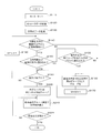
- FIG. 19 shows a flow representing a processing procedure executed by the CPU 41 of the operation terminal 400 in order to realize the grouping method according to this modification.
- step S155 is newly provided between step S150 and step S160 in the flow of FIG. That is, steps S110 to S150 are the same processing as in FIG. 12, and description thereof is omitted.
- step S150 is not satisfied (S150: NO)
- the process proceeds to a new step S155.
- step S155 the CPU 41 sets at least one of the small virtual area Cs (within the 1-fold circle encircling line) of the N-th character stroke data W and the first virtual circle Cs that has been arranged ahead of the small virtual area Cs. Whether or not the virtual region Ct of the character stroke data W (within the encircled line of the 1 ⁇ circle) overlaps (in the example of FIG. 17, “s”, “t”, “i”, “l”, “l”). Determine whether. If the small virtual area Cs overlaps any one of the virtual areas Ct, the determination in step S155 is satisfied (S155: YES), and the process proceeds to step S180 similar to FIG. If the small virtual area Cs does not overlap with any virtual area Ct, the determination in step S155 is not satisfied (S155: NO), and the process proceeds to step S160 similar to FIG. This step S155 corresponds to the third determination procedure described in each claim.
- Steps S160 to S220 are the same as those in FIG.
- the arrow shown in FIG. 2 shows an example of the signal flow, and does not limit the signal flow direction.
Landscapes
- Engineering & Computer Science (AREA)
- Theoretical Computer Science (AREA)
- General Engineering & Computer Science (AREA)
- Physics & Mathematics (AREA)
- General Physics & Mathematics (AREA)
- Human Computer Interaction (AREA)
- Quality & Reliability (AREA)
- Multimedia (AREA)
- Character Discrimination (AREA)
- User Interface Of Digital Computer (AREA)
Abstract
【課題】被筆記媒体への記載内容の変遷を明確にし操作者の利便性を向上する。【解決手段】操作端末のCPUは、電子ペンのストロークデータに対し文字認識処理を行って複数の文字データを生成し、複数の文字データに含まれる任意の第1文字データの第1文字ストロークデータWが、第1文字データの直前に位置する第2文字の第2文字ストロークデータWが生成されてから所定の待機時間内で、かつ、第1文字ストロークデータWを包含する第1仮想領域Cと第2文字ストロークデータWを包含する第2仮想領域Cとの重複部分が存在する場合には、第1文字を、第2文字と共通の1つの文字群G中に組み込んで認識する。
Description
本発明は、操作者による筆記内容を電子データ化するための電子筆記処理プログラム及びそれを記録した記録媒体に関する。
操作者が筆記具を用いて筆記した内容を電子データ化する技術が既に知られている(例えば、特許文献1参照)。この従来技術において、操作者が筆記具(電子ペン)を持って被筆記媒体(紙媒体)の所定の領域(例えば1つのページ)の種々の箇所に所望の順序で複数の文字を適宜に記載すると、上記記載時に移動する筆記具の位置データを含むストロークデータが生成される。生成されたストロークデータは画像データ化され、サーバに送信されて保存される。
上記従来技術では、生成されたストロークデータをそのまま画像データ化したが、これに限られず、ストロークデータに対し適宜の文字認識処理を行い、上記被筆記媒体への記載に対応した文字列データ(複数の文字のテキストデータ)が生成される場合もある。
ところで、操作者が被筆記媒体に筆記を行う場合、すべての文字を一気に記載するとは限らない。例えば、被筆記媒体のある部位へ1つの事柄を記載した後、しばらく時間をおいた後で当該部位に後続する部位に別の事柄を記載し、さらにしばらく時間をおいた後で上記後続する部位にさらに後続する部位にさらに別の事柄を記載する場合等がある。このような場合において、上記文字列データを構成するすべての複数の文字データを特に区切ることなく一括して取り扱うと、上記のような被筆記媒体への実際の記載順序(言い換えれば、文字列に含まれる多数の文字のうち、どの部分がどのような順番で記載されていったかという記載内容の変遷)がわかりにくい場合があった。
本発明の目的は、被筆記媒体への記載内容の変遷を明確にして操作者の利便性を向上できる、電子筆記処理プログラム及びそれを記録した記録媒体を提供することにある。
上記目的を達成するために、本願発明は、被筆記媒体に対する筆記具の移動に伴う前記筆記具の複数の位置データを含み前記筆記具による前記被筆記媒体への文字記載に対応したストロークデータを通信により送信する電子筆記装置に、情報送受信可能に接続された操作端末の演算手段に対し、前記電子筆記装置から受信した前記ストロークデータに対し文字認識処理を行い、対応する複数の文字データを含む文字列データを生成する文字列データ生成手順と、前記複数の文字データに含まれる任意の第1文字データに係わる第1ストロークデータが、前記文字列データ中において前記第1文字データの直前に位置する第2文字データに係わる第2ストロークデータが生成されてから、所定の待機時間内に生成されたか否かを判定する第1判定手順と、前記第1判定手順で前記待機時間内に生成されたと判定された場合に、前記第1ストロークデータを包含する所定の第1仮想領域と、前記第2ストロークデータを包含する所定の第2仮想領域と、の重複部分が存在するか否かを判定する第2判定手順と、前記第2判定手順で前記重複部分が存在すると判定された場合には、前記第1文字データを、前記第2文字データと共通の1つの文字群中に組み込んで認識する文字群認識手順と、を実行させる。
本願発明を実行する操作端末は、電子筆記装置に対し情報送受信可能に接続される。操作者が筆記具を持って被筆記媒体の所定の領域(例えば1つのページ)の種々の箇所に所望の順序で複数の文字を適宜に記載したとき、電子筆記装置において、上記記載時に移動する筆記具の位置データを含むストロークデータが生成され、操作端末へと送信される。操作端末の演算手段が本願発明の電子筆記処理プログラムを実行すると、文字列データ生成手順で、上記電子筆記装置から受信したストロークデータに対し、適宜の文字認識処理を行い、上記被筆記媒体への記載に対応した、複数の文字データを含む文字列データを生成する。
そして、本願発明においてはまず、記載タイミングが互いに遠い文字については、(それらを一体的には取り扱わず)それぞれ別々の群に組み込む。具体的には、第1判定手順において、文字列データを構成する複数の文字データそれぞれについて、当該文字データ(第1文字データ)のストロークデータ(第1ストロークデータ)の生成が、文字列中において直前の記載に相当する文字データ(第2文字データ)のストロークデータ(第2ストロークデータ)の生成から、所定時間(待機時間)内になされたか否が判定される。所定時間外であれば、上記第1文字データと第2文字データとは、(後述の第2判定手順の判定対象となることなく)別々の文字群にそれぞれ組み込まれる。
一方、第1文字データの上記第1ストロークデータの生成が第2文字データの上記第2ストロークデータの生成から所定時間内に行われていた場合には、さらに、第1ストロークデータと第2ストロークデータとが比較的近接した状態にあるかどうか、が判定される。具体的には、第2判定手順において、第1ストロークデータを包含するように仮想される所定の領域(第1仮想領域)と、第2ストロークデータを包含するように仮想される所定の領域(第2仮想領域)とに、重複部分が存在するか否かが判定される。重複部分が存在する場合には、第1ストロークデータと第2ストロークデータとが十分に近接していることから、それらは一体的に取り扱うべきとみなされ、文字群認識手順において、第1文字データと第2文字データとが互いに共通の1つの文字群中に組み込まれる形で認識される。重複部分が存在しない場合は、第1ストロークデータと第2ストロークデータとが近接しておらず別々に取り扱うべきとみなされ、文字群認識手順において、第1文字データと第2文字データとが別々の文字群中にそれぞれ組み込まれる形で認識される。
以上の処理により、本願発明においては、複数の文字データを、それぞれのストロークデータが時間的に比較的近くかつ位置的にも比較的近いデータごとに文字群としてまとめて処理する。これにより、前述のように文字列データを構成するすべての複数の文字データを一括して取り扱う場合と異なり、被筆記媒体への実際の記載順序に沿った記載内容の変遷を明確にすることができるので、操作者にとっての利便性を向上することができる。
本発明によれば、被筆記媒体への記載内容の変遷を明確にして操作者の利便性を向上することができる。
以下、本発明の一実施の形態を図面を参照しつつ説明する。
<システム概略構成>
まず、図1を参照しつつ、本実施形態の電子筆記処理プログラムを実行する操作端末と電子筆記装置とを備えた手書き入力システムの概略構成について説明する。なお、以下の説明では、図1の紙面の上側、下側、右側、左側、手前側、奥行き側を、それぞれ、電子筆記装置の上側、下側、右側、左側、手前側、奥行き側と定義して説明する。
まず、図1を参照しつつ、本実施形態の電子筆記処理プログラムを実行する操作端末と電子筆記装置とを備えた手書き入力システムの概略構成について説明する。なお、以下の説明では、図1の紙面の上側、下側、右側、左側、手前側、奥行き側を、それぞれ、電子筆記装置の上側、下側、右側、左側、手前側、奥行き側と定義して説明する。
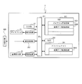
図1に示すように、手書き入力システム1は、電子筆記装置2と、いわゆる電磁誘導式の電子ペン3(筆記具に相当)と、操作端末400とを備える。操作端末400は、無線通信又は有線通信を介して電子筆記装置2と接続され、電子筆記装置2との間で情報の送受を行う。
<電子筆記装置>
電子筆記装置2は、平面視で上下方向に長い薄型の直方体状の形状を備える。この電子筆記装置2の右上部には、種々の情報を表示可能な小型のディスプレイ21が設けられている。ディスプレイ21の左側には、操作者が電子筆記装置2を操作するための入力部22が設けられている。これらディスプレイ21及び入力部22の下側には、電子筆記装置2の手前側の大部分を占めるように、凹部形状の載置部24が設けられている。載置部24には、当該載置部24とほぼ同一の範囲となるように、座標検出部25が設けられている。座標検出部25は、電子ペン3の位置を表す座標データ(位置データに相当。例えば載置部24の左上部を原点(0,0)とする。詳細は後述)を検出する。また、載置部24には、紙媒体70(被筆記媒体に相当。後述の図5参照)が載置される。このとき、載置部24は、紙媒体70を、当該紙媒体70の左上の隅部が上記原点に一致する姿勢で保持する。
電子筆記装置2は、平面視で上下方向に長い薄型の直方体状の形状を備える。この電子筆記装置2の右上部には、種々の情報を表示可能な小型のディスプレイ21が設けられている。ディスプレイ21の左側には、操作者が電子筆記装置2を操作するための入力部22が設けられている。これらディスプレイ21及び入力部22の下側には、電子筆記装置2の手前側の大部分を占めるように、凹部形状の載置部24が設けられている。載置部24には、当該載置部24とほぼ同一の範囲となるように、座標検出部25が設けられている。座標検出部25は、電子ペン3の位置を表す座標データ(位置データに相当。例えば載置部24の左上部を原点(0,0)とする。詳細は後述)を検出する。また、載置部24には、紙媒体70(被筆記媒体に相当。後述の図5参照)が載置される。このとき、載置部24は、紙媒体70を、当該紙媒体70の左上の隅部が上記原点に一致する姿勢で保持する。
<電子ペン>
電子ペン3は、金属製の芯37と、検出スイッチ33と、ボタン型の電池34と、コイル35と、基板36とを備える。芯37は、電子ペン3の先端部の内部に設けられており、外部に突出したペン先31と、インク収納部32とで構成されている。インク収納部32には、インクが収納されており、インクは、ペン先31に供給される。これにより、操作者は、電子ペン3を使用して紙媒体70に所望の文字や図像等を記載(記入)することができる。なお、以下の説明では、電子ペン3において、ペン先31が設けられている方向を先端方向、先端方向の反対方向を後端方向という。
電子ペン3は、金属製の芯37と、検出スイッチ33と、ボタン型の電池34と、コイル35と、基板36とを備える。芯37は、電子ペン3の先端部の内部に設けられており、外部に突出したペン先31と、インク収納部32とで構成されている。インク収納部32には、インクが収納されており、インクは、ペン先31に供給される。これにより、操作者は、電子ペン3を使用して紙媒体70に所望の文字や図像等を記載(記入)することができる。なお、以下の説明では、電子ペン3において、ペン先31が設けられている方向を先端方向、先端方向の反対方向を後端方向という。
芯37の後端方向には、上記基板36が設けられている。基板36の先端部には、上記検出スイッチ33が実装されている。検出スイッチ33は、基板36上の配線を介し上記コイル35に電気的に接続されている。コイル35は、電子ペン3の内部の先端部において芯37の周囲に巻回されている。また、基板36の後端方向には、上記電池34が設けられている。電池34は、基板36に接続されており、マイナス側の電極は、基板36上の配線を介しコイル35に電気的に接続され、プラス側の電極は、基板36上の配線を介し検出スイッチ33に電気的に接続されている。
<電子ペンの座標データの検出>
ここで、芯37は、図示しない弾性部材により常に先端方向に付勢されている。芯37は、操作者が紙媒体70に文字や図像等を記載する場合の押圧力によって、上記弾性部材の付勢力に抗して電子ペン3の内部にやや退いて入り込む。この動作によって、芯37の後端部が検出スイッチ33を押下し、検出スイッチ33がオン状態になる。これによって、電池34とコイル35とが導通して電池34からコイル35に向かって電流が流れ、コイル35に電流が流れることで磁界が発生する。
ここで、芯37は、図示しない弾性部材により常に先端方向に付勢されている。芯37は、操作者が紙媒体70に文字や図像等を記載する場合の押圧力によって、上記弾性部材の付勢力に抗して電子ペン3の内部にやや退いて入り込む。この動作によって、芯37の後端部が検出スイッチ33を押下し、検出スイッチ33がオン状態になる。これによって、電池34とコイル35とが導通して電池34からコイル35に向かって電流が流れ、コイル35に電流が流れることで磁界が発生する。
上記座標検出部25は、上記のようにしてコイル35から発生する磁界を電磁誘導に基づき検出する。なお、この検出は公知の手法で足りるので、詳細な説明は省略する。この座標検出部25の検出結果に基づき、後述のCPU201は、操作者が電子ペン3を用いて紙媒体70へ筆記動作を行ったときの電子ペン3の移動に対応する、電子ペン3の離散的な複数の上記座標データを取得する。本実施形態では、載置部24(座標検出部25)の左上部の座標(X,Y)を原点(0,0)とし、右方向をX軸、下方向をY軸とする座標系を用いる。すなわち、X座標の値が載置部24(座標検出部25)における左右方向の位置を表し、Y座標の値が載置部24(座標検出部25)における上下方向の位置を表す。
そして、上記のようにして取得された複数の座標データに基づき、後述のCPU201によって、操作者が電子ペン3を用いて紙媒体70へ記載した文字や図像等に対応するストロークデータ(詳細は後述)が生成される。
<電子筆記装置の電気的構成>
次に、図2を参照しつつ、電子筆記装置2の電気的構成について説明する。
次に、図2を参照しつつ、電子筆記装置2の電気的構成について説明する。
図2に示すように、電子筆記装置2は、当該電子筆記装置2の制御を行うCPU201と、ROM202と、種々のデータが一時的に記憶されるRAM203と、フラッシュメモリ204と、上記入力部22と、駆動回路206,209と、上記操作端末400との情報送受信の制御を行う通信制御部207とを備える。
ROM202、RAM203、及びフラッシュメモリ204は、CPU201に電気的に接続されている。ROM202は、プログラム記憶領域2021と、画像データ記憶領域2023とを備える。プログラム記憶領域2021には、CPU201が実行する座標データ処理プログラム(後述の図11のフローに示す各手順を実行するプログラム)を初めとする各種のプログラムが記憶されている。画像データ記憶領域2023には、例えば紙媒体70のフォーマット情報に対応した画像データが記憶されている。
フラッシュメモリ204は、座標データ記憶領域2041を備える。座標データ記憶領域2041には、上述のようにして座標検出部25の検出結果に基づきCPU201により取得される複数の座標データが順次記憶される。
RAM203には、座標データ記憶領域2041に記憶された複数の座標データに基づき生成されたストロークデータが一時的に記憶される。
入力部22及び駆動回路206,209は、CPU201に電気的に接続されている。駆動回路206,209は、それぞれ、上記ディスプレイ21及び座標検出部25を駆動するための電子回路である。
<ストロークデータの生成>
次に、図3を参照しつつ、ストロークデータについて説明する。
次に、図3を参照しつつ、ストロークデータについて説明する。
図3において、ストロークデータは、上記座標検出部25の検出結果に基づきCPU201により取得された複数の座標データからなるペン位置データ列である。図3(a)及び図3(b)には、2つのストロークデータ「a」「b」の例を示している。
図3(a)及び図3(b)に示すように、第1ストロークデータ「a」は、電子ペン3による文字「a」の書き始めから書き終わりまでの一筆書き部分の軌跡を表すデータであり、時系列に沿って、ペン位置番号T1,T2,・・,T11それぞれに対応した、11個の座標データ(X1,Y1),(X2,Y2),・・,(X11,Y11)を含む。また、第2ストロークデータ「b」は、電子ペン3による文字「b」の書き始めから書き終わりまでの一筆書き部分の軌跡を表すデータであり、時系列に沿って、ペン位置番号T12,T13,・・,T21それぞれに対応した、10個の座標情報(X12,Y12),(X13,Y13),・・(X21,Y21)を含む。このようにして、CPU201は、座標検出部25の検出結果に基づく複数の座標データに基づき、操作者が電子ペン3を用いて紙媒体70へ記載した文字や図像等に対応するストロークデータを生成する。
電子筆記装置2で生成されたストロークデータは、通信制御部207を介して操作端末400に送信される。
<操作端末の機能的構成>
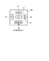
操作端末400の機能的構成を図4に示す。操作端末400は、CPU41(演算手段に相当)と、記録媒体としてのメモリ42と、操作ボタン等の操作部43と、表示部44(表示手段に相当)と、通信制御部45等を備えている。
操作端末400の機能的構成を図4に示す。操作端末400は、CPU41(演算手段に相当)と、記録媒体としてのメモリ42と、操作ボタン等の操作部43と、表示部44(表示手段に相当)と、通信制御部45等を備えている。
CPU41は、メモリ42に予め記憶された本実施形態に係る電子筆記処理プログラム(後述する図12に示す手順を実行するためのプログラム)を初めとする各種プログラムを実行するとともに、操作端末400の全体を制御する。CPU41は、上記電子筆記処理プログラムの実行によって、電子筆記装置2から送信されたストロークデータに対し文字認識処理を行い、認識した複数の文字データを含む文字列データを生成する。
メモリ42は、記憶内容の追加及び消去が可能な、例えばElectrically Erasable Programmable Read-Only Memory(EEPROM)等の不揮発性メモリから構成されている。このメモリ42には、CPU41が実行する上記電子筆記処理プログラムを含む各種プログラムが記憶されている。
操作部43は、操作端末400の各種操作を行うための操作ボタンや操作キーを備えている。そして、例えば操作部43の操作によって操作端末400の電源がオンされると、上記電子筆記処理プログラムの実行が開示される。
表示部44は、所定の表示機能を備えており、上記ストロークデータから生成された文字列データを適宜にグループ化して表示する(詳細は後述)。
通信制御部45は、無線通信(又は有線通信)を介して電子筆記装置2と接続され、情報通信の制御を行う。電子筆記装置2から送信されたストロークデータは、通信制御部45を介して操作端末400に受信される。
<文字列データの生成>
以上のようにして、電子筆記装置2の上記載置部24に載置された紙媒体70に対し、操作者が電子ペン3を用いて所望の文字や図像等を記載すると、座標検出部25の検出結果に基づく複数の座標データに基づき、CPU201が、記載された文字や図像等に対応するストロークデータを生成する。生成されたストロークデータは電子筆記装置2から操作端末400に送信される。操作端末400では、CPU41が、受信したストロークデータに対し公知の文字認識処理を行い、ストロークデータに対応した複数の文字データを含む文字列データを生成する。
以上のようにして、電子筆記装置2の上記載置部24に載置された紙媒体70に対し、操作者が電子ペン3を用いて所望の文字や図像等を記載すると、座標検出部25の検出結果に基づく複数の座標データに基づき、CPU201が、記載された文字や図像等に対応するストロークデータを生成する。生成されたストロークデータは電子筆記装置2から操作端末400に送信される。操作端末400では、CPU41が、受信したストロークデータに対し公知の文字認識処理を行い、ストロークデータに対応した複数の文字データを含む文字列データを生成する。
<文字列データにおける不都合が生じる例>
図5に、上記載置部24上の紙媒体70に対し操作者が電子ペン3を用いて所望の文字や図像等の記載を記入した場合の一例を示す。
図5に、上記載置部24上の紙媒体70に対し操作者が電子ペン3を用いて所望の文字や図像等の記載を記入した場合の一例を示す。
図5に示す例では、紙媒体70に、所望の文字や図像等の記載Rとして、「system is still sound that is new」という横書きの一群の文字列Tが、上下2段に亘って記入されている。なお、紙媒体70の適宜の箇所(この例では右下の隅部)には、座標データ記憶領域2041に記憶された複数の座標データを操作端末400に送信するための、保存ボックス72が設けられている。
ここで、操作者が紙媒体70に筆記を行う場合、すべての文字を一気に記載するとは限らない。例えば、紙媒体70のある部位へ1つの事柄を記載した後、しばらく時間をおいた後で当該部位に後続する部位に別の事柄を記載し、さらにしばらく時間をおいた後で上記後続する部位にさらに後続する部位にさらに別の事柄を記載する場合等がある。このような場合において、操作端末400でストロークデータに対する文字認識処理で生成された文字列データについて、文字列データを構成するすべての複数の文字データを特に区切ることなく一括して取り扱うと、上記のような紙媒体70への実際の記載順序(言い換えれば、文字列に含まれる多数の文字のうち、どの部分がどのような順番で記載されていったかという記載内容の変遷)がわかりにくい場合があり得る。
例えば図5に示した「systemisstillsoundthatisnew」の文字列Tの例では、例えば操作者が、「System is still, sound that is new~」という意図で記載した場合が考えられる。この場合は、stillのところで文節が区切られており、この文章の意味は、「システムは静かである。新しく○○な音は、・・」のようになる。その一方で、操作者が、「System is still sound, that is new~」という意図で記載した場合も考えられる。この場合は、soundのところで文節が区切られており、この文章の意味は、「システムはまだ丈夫である。それは、新しい○○である。」のようになる。
<本実施形態の特徴>
本実施形態では、上記に対応するために、操作端末400において、ストロークデータから生成された文字列データを構成する各文字データについて、筆記時の互いの記載タイミングが時間的に比較的近いか否か、を判定する。そして、時間的に比較的近かった場合には、さらに各文字データの上記ストロークデータ同士の距離が比較的近いか否か、を判定する。そして、ストロークデータ同士の距離が比較的近い文字データごとに、1つの文字群にまとめる処理(以下適宜、単に「グループ化」を行う。
本実施形態では、上記に対応するために、操作端末400において、ストロークデータから生成された文字列データを構成する各文字データについて、筆記時の互いの記載タイミングが時間的に比較的近いか否か、を判定する。そして、時間的に比較的近かった場合には、さらに各文字データの上記ストロークデータ同士の距離が比較的近いか否か、を判定する。そして、ストロークデータ同士の距離が比較的近い文字データごとに、1つの文字群にまとめる処理(以下適宜、単に「グループ化」を行う。
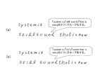
上記図5の「systemisstillsoundthatisnew」の文字列Tの場合を例にとると、図6(a)に示すように、「s」「y」「s」「t」「e」「m」「i」「s」の各ストロークデータが互いに比較的近く、「s」「t」「i」「l」「l」「s」「o」「u」「n」「d」の各ストロークデータが互いに比較的近く、「t」「h」「a」「t」「i」「s」「n」「e」「w」の各ストロークデータが互いに比較的近く、「is」の「s」と「still」の「s」の各ストロークデータが比較的離れており、「sound」の「d」と「that」の最初の「t」の各ストロークデータが比較的離れている場合には、前述の文字認識による文字データ生成後の文字列データ「systemisstillsoundthatisnew」を、「systemis」の文字群と、「stillsound」の文字群と、「thatisnew」の文字群とに切り分けた後、公知の辞書ファイル等(例えば予めメモリ42に格納されている)を用いることによって、「system is」の文字群と、「still sound」の文字群と、「that is new」の文字群との、3つにグループ化する。
あるいは、図6(b)に示すように、「s」「y」「s」「t」「e」「m」「i」「s」の各ストロークデータが互いに比較的近く、「s」「t」「i」「l」「l」の各ストロークデータが互いに比較的近く、「s」「o」「u」「n」「d」「t」「h」「a」「t」「i」「s」「n」「e」「w」の各ストロークデータが互いに比較的近く、「is」の「s」と「still」の「s」の各ストロークデータが比較的離れており、「still」の最後の「l」と「sound」の「s」の各ストロークデータが比較的離れている場合には、前述の文字認識による文字データ生成後の文字列データ「systemisstillsoundthatisnew」を、「systemis」の文字群と、「still」の文字群と、「soundthatisnew」の文字群とに切り分けた後、上記辞書ファイル等を用いることによって、「system is」の文字群と、「still」の文字群と、「sound that is new」の文字群との、3つにグループ化する。
<グループ化の詳細>
上記グループ化の手法の詳細を、図7及び図8により説明する。まず、上記図6(b)に示したグループ化の詳細を図7(a)~図7(e)に示す。図7(a)において、上記文字列Tの「systemisstillsoundthatisnew」を構成する「s」「y」「s」「t」「e」「m」「i」「s」「st」「i」「l」「l」「s」「o」「u」「n」「d」「t」「h」「a」「t」「i」「s」「n」「e」「w」の各文字のストロークデータW(複数の座標データから構成される。なお、以下適宜、「文字ストロークデータW」と称する)は、それぞれ、隣接する文字ストロークデータWと互いに時間的に比較的近いデータとして生成されている。ここで、時間的に比較的近いとは、文字列T中の任意の1つの文字の文字ストロークデータWが、その直前に位置する別の文字ストロークデータWが生成されてから、所定の待機時間(例えば0.5秒)以内に生成された場合を指す。さらに高精度とする場合、詳細には、上記1つの文字ストロークデータWの最初の座標データ(例えば図3(b)に示すペン位置番号T12のデータ)が、その直前に位置する別の文字ストロークデータWの最後の座標データ(例えば図3(b)に示すペン位置番号T11のデータ)が生成されてから上記待機時間以内に生成された場合とすればよい。なお、上記待機時間は、上記文字ストロークデータWを構成する各座標データにそれぞれ付随する電子ペン3の移動時の時刻データ(図示省略)から算出することができる。
上記グループ化の手法の詳細を、図7及び図8により説明する。まず、上記図6(b)に示したグループ化の詳細を図7(a)~図7(e)に示す。図7(a)において、上記文字列Tの「systemisstillsoundthatisnew」を構成する「s」「y」「s」「t」「e」「m」「i」「s」「st」「i」「l」「l」「s」「o」「u」「n」「d」「t」「h」「a」「t」「i」「s」「n」「e」「w」の各文字のストロークデータW(複数の座標データから構成される。なお、以下適宜、「文字ストロークデータW」と称する)は、それぞれ、隣接する文字ストロークデータWと互いに時間的に比較的近いデータとして生成されている。ここで、時間的に比較的近いとは、文字列T中の任意の1つの文字の文字ストロークデータWが、その直前に位置する別の文字ストロークデータWが生成されてから、所定の待機時間(例えば0.5秒)以内に生成された場合を指す。さらに高精度とする場合、詳細には、上記1つの文字ストロークデータWの最初の座標データ(例えば図3(b)に示すペン位置番号T12のデータ)が、その直前に位置する別の文字ストロークデータWの最後の座標データ(例えば図3(b)に示すペン位置番号T11のデータ)が生成されてから上記待機時間以内に生成された場合とすればよい。なお、上記待機時間は、上記文字ストロークデータWを構成する各座標データにそれぞれ付随する電子ペン3の移動時の時刻データ(図示省略)から算出することができる。
そして、図7(a)に示すように、文字列Tを構成する各文字の文字ストロークデータWを包含するような領域(以下適宜、「仮想領域」という。この例では、各文字ストロークデータWの文字高さの2倍の直径を備えた略円形の包囲線である、2倍円内の領域)Cを仮想する。そして、前後2つの文字ストロークデータW、すなわち例えば「y」の文字ストロークデータW(第1ストロークデータに相当)の上記仮想領域C(第1仮想領域に相当)と、その直前の「s」の文字ストロークデータW(第2ストロークデータに相当)の仮想領域C(第2仮想領域に相当)同士とが、重複しているか否かが判定される。図7(a)に示すように重複している場合には、後の文字ストロークデータWを文字認識して生成された文字データ「y」(図示省略)が、前の文字ストロークデータWを文字認識して生成された文字データ「s」(図示省略)と共通の1つの文字群(後述の図7(b)~(e)参照)に組み込まれる。すなわち、この時点で文字群「sy」が形成されることとなる。
その後、上記同様、「y」の後の「s」の文字ストロークデータWの仮想領域Cが、直前の上記「y」の文字ストロークデータWの仮想領域Cと重複するので、上記文字群「sy」に「s」がさらに組み込まれ、文字群「sys」が形成される。以降同様に、「t」「e」「m」「i」「s」それぞれの文字ストロークデータWの仮想領域Cが、直前の文字の文字ストロークデータWの仮想領域Cと重複するので、各文字データがさらに順次組み込まれ、文字群「systemis」が形成される。
その後、「is」の後の「s」の文字ストロークデータWの仮想領域Cは、直前の上記「is」の「s」の文字ストロークデータWの仮想領域Cと重複しないことから、「is」の後の「s」の文字データは上記文字群「systemis」には組み込まれず、単独で別の1つの文字群に組み込まれることとなる。これ以降、上記同様の手法により、文字データ「t」「i」「l」「l」がそれぞれ順次上記文字データ「s」と共通の文字群に組み込まれることで、文字群「still」が形成される。
さらにその後、「still」の後の「s」の文字ストロークデータWの仮想領域Cは、直前の上記「l」の文字ストロークデータWの仮想領域Cと重複せず、上記同様、単独で別の1つの文字群に組み込まれ、以降、上記同様にして、文字データ「o」「u」「n」「d」「t」「h」「a」「t」「i」「s」「n」「e」「w」がそれぞれ順次上記文字データ「s」と共通の文字群に組み込まれることで、文字群「soundthatisnew」が形成される。
以上の結果、「systemisstillsoundthatisnew」の文字列Tは、文字認識されてテキストデータ化された後に、前述のように辞書ファイルを用いることによって、図7(b)に示すように、文字群「system is」、文字群「still」、文字群「sound that is new」に3グループ化される。
そして、上記文字群「system is」「still」「sound that is new」は、上記表示部44において、(それら全部が一覧表示されるのでなく)時系列的に順次表示される。すなわち、まず、図7(c)に示すように、表示部44は、「system is」の文字群Gが表示された状態となり、その後の適宜のタイミングで、図7(d)に示すように、「system is」の文字群Gと「still」の文字群Gとが表示された状態(すなわち文字群「still」が追加して表示された状態)となり、さらにその後の適宜のタイミングで、図7(e)に示すように、「system is」の文字群G、「still」の文字群G、「sound that is new」の文字群Fが表示された状態(すなわち文字群「sound that is new」が追加して表示された状態)となる。
一方、上記図6(a)に示したグループ化の詳細を図8(a)~図8(e)に示す。図8(a)において、図7と同様、「s」「y」「s」「t」「e」「m」「i」「s」「st」「i」「l」「l」「s」「o」「u」「n」「d」「t」「h」「a」「t」「i」「s」「n」「e」「w」の各文字ストロークデータWは、隣接する文字ストロークデータWと互いに時間的に比較的近いデータとして生成されている。そして、上記同様、まず最初の文字群「systemis」が形成される。
その後、「is」の後の「s」の文字ストロークデータWの仮想領域Cは直前の上記「is」の「s」の文字ストロークデータWの仮想領域Cと重複せず、その後の「t」の文字ストロークデータWの仮想領域Cは直前の上記「s」の文字ストロークデータWの仮想領域Cと重複して「s」と共通の文字群に組み込まれ、以降同様にして、文字データ「i」「l」「l」「s」「o」「u」「n」「d」がそれぞれ順次上記文字データ「s」と共通の文字群に組み込まれることで、文字群「stillsound」が形成される。
さらにその後、「sound」の後の「t」の文字ストロークデータWの仮想領域Cは、直前の上記「d」の文字ストロークデータWの仮想領域Cと重複せず、その後の「h」の文字ストロークデータWの仮想領域Cは直前の上記「t」の文字ストロークデータWの仮想領域Cと重複して「t」と共通の文字群に組み込まれ、以降同様にして、文字データ「a」「t」「i」「s」「n」「e」「w」が上記文字データ「t」と共通の文字群に組み込まれることで、文字群「thatisnew」が形成される。
以上の結果、図8の例では、「systemisstillsoundthatisnew」の文字列Tは、文字認識されてテキストデータ化された後に、前述のように辞書ファイルを用いることによって、図8(b)に示すように、文字群「system is」、文字群「still sound」、文字群「that is new」に3グループ化される。
そして、上記文字群「system is」「still sound」「that is new」は、上記同様、表示部44において時系列的に順次表示される。すなわち、まず、図8(c)に示すように、表示部44は、「system is」の文字群Gが表示された状態となり、その後の適宜のタイミングで、図8(d)に示すように、「system is」の文字群Gと「still sound」の文字群Gとが表示された状態(すなわち文字群「still sound」が追加して表示された状態)となり、さらにその後の適宜のタイミングで、図8(e)に示すように、「system is」の文字群G、「still sound」の文字群G、「that is new」の文字群Fが表示された状態(すなわち文字群「that is new」が追加して表示された状態)となる。
<日本語の文字列データのグループ化の例>
上記は英語の文字列データの処理の例であったが、上記同様の手法は、日本語の文字列データにも適用できる。そのような例を図9及び図10により説明する。
上記は英語の文字列データの処理の例であったが、上記同様の手法は、日本語の文字列データにも適用できる。そのような例を図9及び図10により説明する。
例えば、図9(a)において、文字列「最大値となっているところが近年は」を構成する「最」「大」「値」「と」「な」「っ」「て」「い」「る」「と」「こ」「ろ」「が」「近」「年」「は」の各文字ストロークデータWは、前述と同様、それぞれ、隣接する文字ストロークデータWと互いに時間的に比較的近いデータとして生成されている。
そして、図9(a)に示すように、文字列Tを構成する各文字の文字ストロークデータWを包含する上記同様の仮想領域について、前後2つの文字ストロークデータW、すなわち例えば「大」の文字ストロークデータW(第1ストロークデータに相当)の上記仮想領域C(第1仮想領域に相当)と、その直前の「最」の文字ストロークデータW(第2ストロークデータに相当)の仮想領域C(第2仮想領域に相当)同士とが、重複しているか否かが判定される。図9(a)に示すように重複している場合には、後の文字ストロークデータWを文字認識して生成された文字データ「大」(図示省略)が、前の文字ストロークデータWを文字認識して生成された文字データ「最」(図示省略)と共通の1つの文字群(後述の図9(b)~(e)参照)に組み込まれる。すなわち、この時点で文字群「最大」が形成されることとなる。
その後、上記同様、「値」の文字ストロークデータWの仮想領域Cが、直前の上記「大」の文字ストロークデータWの仮想領域Cと重複するので、上記文字群「最大」に「値」がさらに組み込まれ、文字群「最大値」が形成される。さらに、「と」の文字ストロークデータWの仮想領域Cが、直前の上記「値」の文字ストロークデータWの仮想領域Cと重複するので、上記文字群「最大値」に「と」の文字データがさらに組み込まれ、文字群「最大値と」が形成される。
その後、「な」の文字ストロークデータWの仮想領域Cは、直前の上記「と」の文字ストロークデータWの仮想領域Cと重複しないことから、「な」の文字データは上記文字群「最大値」には組み込まれず、単独で別の1つの文字群に組み込まれることとなる。これ以降、上記同様の手法により、文字データ「っ」「て」「い」「る」がそれぞれ順次上記文字データ「な」と共通の文字群に組み込まれることで、文字群「なっている」が形成される。
さらにその後、「と」の文字ストロークデータWの仮想領域Cは、直前の上記「る」の文字ストロークデータWの仮想領域Cと重複せず、上記同様、単独で別の1つの文字群に組み込まれ、以降、上記同様にして、文字データ「と」「こ」「ろ」「が」「近」「年」「は」がそれぞれ順次上記文字データ「と」と共通の文字群に組み込まれることで、文字群「ところが近年は」が形成される。
以上の結果、「最大値となっているところが近年は」の文字列Tは、文字認識されてテキストデータ化された後に、図9(b)に示すように、文字群「最大値と」、文字群「なっている」、文字群「ところが近年は」に3グループ化される。なおこのように日本語の文字列データに対し処理を行うときには、前述と異なり、辞書ファイルは必ずしも使用しなくても良い。
そして、上記文字群「最大値と」「なっている」「ところが近年は」は、前述と同様、上記表示部44において時系列的に順次表示される。すなわち、まず、図9(c)に示すように、表示部44は、「最大値と」の文字群Gが表示された状態となり、その後の適宜のタイミングで、図9(d)に示すように、「最大値と」の文字群Gと「なっている」の文字群Gとが表示された状態(すなわち文字群「なっている」が追加して表示された状態)となり、さらにその後の適宜のタイミングで、図9(e)に示すように、「最大値と」の文字群G、「なっている」の文字群G、「ところが近年は」の文字群Fが表示された状態(すなわち文字群「ところが近年は」が追加して表示された状態)となる。
一方、日本語の文字列データのグループ化の別の例を図10(a)~図10(e)に示す。図10(a)において、上記図9と同様、「最」「大」「値」「と」「な」「っ」「て」「い」「る」「と」「こ」「ろ」「が」「近」「年」「は」の各文字ストロークデータWは、隣接する文字ストロークデータWと互いに時間的に比較的近いデータとして生成されている。そして、上記同様、まず最初の文字群「最大値と」が形成される。
その後、「な」の文字ストロークデータWの仮想領域Cは直前の上記「と」の文字ストロークデータWの仮想領域Cと重複せず、その後の「っ」の文字ストロークデータWの仮想領域Cは直前の上記「な」の文字ストロークデータWの仮想領域Cと重複して「な」と共通の文字群に組み込まれ、以降同様にして、文字データ「て」「い」「る」「と」「こ」「ろ」「が」がそれぞれ順次上記文字データ「な」と共通の文字群に組み込まれることで、文字群「なっているところが」が形成される。
さらにその後、「近」の文字ストロークデータWの仮想領域Cは、直前の上記「が」の文字ストロークデータWの仮想領域Cと重複せず、その後の「年」の文字ストロークデータWの仮想領域Cは直前の上記「近」の文字ストロークデータWの仮想領域Cと重複して「近」と共通の文字群に組み込まれ、以降同様にして、文字データ「は」が上記文字データ「近」と共通の文字群に組み込まれることで、文字群「近年は」が形成される。
以上の結果、図10の例では、「最大値となっているところが近年は」の文字列Tは、文字認識されてテキストデータ化された後に、図10(b)に示すように、文字群「最大値と」、文字群「なっているところが」、文字群「近年は」に3グループ化される。
そして、上記文字群「最大値と」「なっているところが」「近年は」は、上記同様、表示部44において時系列的に順次表示される。すなわち、まず、図10(c)に示すように、表示部44は、「最大値と」の文字群Gが表示された状態となり、その後の適宜のタイミングで、図10(d)に示すように、「最大値と」の文字群Gと「なっているところが」の文字群Gとが表示された状態(すなわち文字群「なっているところが」が追加して表示された状態)となり、さらにその後の適宜のタイミングで、図10(e)に示すように、「最大値と」の文字群G、「なっているところが」の文字群G、「近年は」の文字群Fが表示された状態(すなわち文字群「近年は」が追加して表示された状態)となる。
<電子筆記装置の制御手順>
次に、図11を参照しつつ、ストロークデータ生成時の電子筆記装置2のCPU201が実行する制御手順を説明する。図11に示すフローは、例えば、電子筆記装置2の電源がオンされると開始される。
次に、図11を参照しつつ、ストロークデータ生成時の電子筆記装置2のCPU201が実行する制御手順を説明する。図11に示すフローは、例えば、電子筆記装置2の電源がオンされると開始される。
まず、ステップS10で、CPU201は、操作者が紙媒体70に筆記を行ったときの座標検出部25の検出結果に基づき、前述のようにして電子ペン3の複数の座標データを取得する。取得された座標データは、座標データ記憶領域2041に順次記憶される。ステップS10が終了すると、ステップS20に移る。
ステップS20では、CPU201は、上記ステップS10で取得した座標データの保存指示(上記保存ボックス72へのチェックマーク記入)が行われたか否かを判定する。操作者が紙媒体70に設けられた保存ボックス72にチェックマークを記入するまではステップS20の判定は満たされず(S20:NO)、上記ステップS10に戻り同様の手順を繰り返す。チェックマークの記入が行われるとステップS20の判定が満たされて(S20:YES)、ステップS30に移る。
ステップS30では、CPU201は、上記ステップS10で座標データ記憶領域2041に記憶された複数の座標データに基づき、操作者による紙媒体70への上記記載Rに対応するストロークデータを生成する。なお、生成されたストロークデータは、RAM203に一時的に記憶される。ステップS30が終了すると、ステップS40に移る。
ステップS40では、CPU201は、ステップS30でRAM203に記憶されたストロークデータを通信制御部207を介して操作端末400に送信する。その後、このフローを終了する。
<操作端末の制御手順>
次に、上記図7及び図8等に示したグループ化の手法を実現するために操作端末400のCPU41が実行する処理手順を表すフローを図12に示す。図12に示すフローは、例えば、操作端末400の電源がオンされると開始される。
次に、上記図7及び図8等に示したグループ化の手法を実現するために操作端末400のCPU41が実行する処理手順を表すフローを図12に示す。図12に示すフローは、例えば、操作端末400の電源がオンされると開始される。
まず、ステップS110で、CPU41は、文字列Tに対応した全ストロークデータ中の各文字ストロークデータWの順番を表す変数NをN=2に、文字群Gの順番を表す変数MをM=1に初期化する。ステップS110が終了すると、ステップS120に移る。
ステップS120では、CPU41は、上記図11のステップS40において電子筆記装置2から送信されたストロークデータ(図7図8の例では「s」「y」「s」「t」「e」「m」「i」「s」「s」「t」「i」「l」「l」「s」「o」「u」「n」「d」「t」「h」「a」「t」「i」「s」「n」「e」「w」の各文字ストロークデータW)を、上記通信制御部45を介して受信し取得する。ステップS120が終了すると、ステップS130に移る。
ステップS130では、CPU41は、上記ステップS120で取得したストロークデータに対し公知の手法により文字認識処理を行い、対応する文字列データ(図7図8の例では、「s」「y」「s」「t」「e」「m」「i」「s」「s」「t」「i」「l」「l」「s」「o」「u」「n」「d」「t」「h」「a」「t」「i」「s」「n」「e」「w」の各文字データを含む、「systemisstillsoundthatisnew」の文字列データ)を生成する。なお、このステップS130が各請求項記載の文字列データ生成手順に相当する。
その後、ステップS140では、CPU41は、上記ステップS130で生成した文字列データのN番目の文字ストロークデータWが、直前の文字ストロークデータWから所定時間(前述の例では0.5秒)内に生成された否かを判定する。最初のN=2の場合には2番目の文字データ「y」(第1文字データに相当)に係わる上記「y」の文字ストロークデータWが、直前の1番目の文字データ「s」(第2文字データに相当)に係わる上記「s」の文字ストロークデータWから、上記所定時間内に生成されたか否かが判定される。なお、前述したように、精度よく判定を行いたい場合は、N番目の文字ストロークデータWの最初の座標データが、その直前の文字ストロークデータWの最後の座標データが生成されてから上記待機時間以内に生成されたか否かが判定される。上記所定時間内に生成されていればステップS140の判定が満たされ(S140:YES)、ステップS150に移る。所定時間内に生成されていない場合はステップS140の判定が満たされず(S140:NO)、後述のステップS160に移る。なお、このステップS140が第1判定手順に相当する。
ステップS150では、CPU41は、N番目の文字ストロークデータW(第1文字データ)の仮想領域C(前述の2倍円)と直前の文字ストロークデータW(第2文字データ)の仮想領域C(前述の2倍円)同士が重複するか否かを判定する。最初のN=2の場合には2番目の「y」の文字ストロークデータWを包含する仮想領域C(図7(a)図8(a)参照)が、直前の1番目の「s」の文字ストロークデータWを包含する仮想領域Cと重複するか否かが判定される。上記第1文字ストロークデータWと上記第2文字ストロークデータWの仮想領域C同士が重複する場合はステップS150の判定が満たされ(S150:YES)、後述のステップS180に移る。上記第1文字ストロークデータWと上記第2文字ストロークデータWの仮想領域C同士が重複しない場合はステップS150の判定が満たされず(S150:NO)、ステップS160に移る。なお、このステップS150が各請求項記載の第2判定手順に相当する。
上記ステップS140及びステップS150から移行したステップS160では、CPU41は、直前の文字データまでの全部の文字データを第Mグループとして1つの文字群Gにグループ化する。前述の例の最初のN=2の場合には2番目の文字データ「y」の直前の1番目の文字データ「s」が、単独で文字群Gを形成する。なお、例えばこのステップS160で、前述の辞書ファイルの参照を行っても良い。ステップS160が終了すると、ステップS170に移る。なお、このステップS160が各請求項記載の文字群認識手順に相当する。
ステップS170では、CPU41は、文字群Gの順番変数Mを1つ増やす。ステップS170が終了すると、ステップS180に移る。
ステップS180では、CPU41は、ステップS130で生成した文字列データに含まれるすべての文字データについて、上記ステップS160のグループ化が終了したか否かを判定する。全部の文字データについて上記ステップS160のグループ化が終了していない場合はステップS180の判定が満たされず(S180:NO)、ステップS190に移る。全部の文字データについてグループ化が終了した場合はステップS180の判定が満たされ(S180:YES)、後述のステップS200に移る。
ステップS190では、CPU41は、上記変数Nを1つ増やしてN=N+1とした後、上記ステップS140に戻り、同様の手順を繰り返す。これにより、例えば前述の図7(a)に示した例では、文字データ「s」「y」「s」「t」「e」「m」「i」「s」については、ステップS140→ステップS150→ステップS180→ステップS190→ステップS140・・の各手順が繰り返され、その後の文字データ「s」についてステップS140を経てステップS150の判定が満たされないことから、ステップS160でそれまでの上記文字データ「s」「y」「s」「t」「e」「m」「i」「s」で文字群「systemis」が形成される(この例ではさらに辞書ファイルを用いることで「system is」となる)。その後、ステップS170及びステップS180を経て、上記同様に「t」「i」「l」「l」についてステップS140→ステップS150→ステップS180→ステップS190→ステップS140・・の各手順が繰り返され、その後の文字データ「s」についてステップS140を経てステップS150の判定が満たされないことから、ステップS160でそれまでの上記文字データ「s」「t」「i」「l」「l」で文字群「still」が形成される。さらにその後、ステップS170及びステップS180を経て、上記同様にその後の「o」「u」「n」「d」「t」「h」「a」「t」「i」「s」「n」「e」「w」についてステップS140→ステップS150→ステップS180→ステップS190→ステップS140・・の各手順が繰り返される。そして、文字データ「w」についてステップS180の判定が満たされて、ステップS200に移る。
ステップS200では、CPU41は、上記文字列データ中のグループ化されていない残りの全文字データをグループ化する。これにより、上記図7(a)の例では、残りの上記文字データ「s」「o」「u」「n」「d」「t」「h」「a」「t」「i」「s」「n」「e」「w」で文字群「soundthatisnew」が形成される(この例ではさらに辞書ファイルを用いることで「sound that is new」となる)。ステップS200が終了すると、ステップS210に移る。
ステップS210では、CPU41は、表示部44に制御信号を出力し、グループ化された文字群Gの文字列をグループ番号M=1から各順番のグループ単位で表示部44に表示させる。ステップS210が終了すると、ステップS220に移る。このステップS210が各請求項記載の文字群表示手順に相当する。
ステップS220では、CPU41は、最後の順番の文字群Gの文字列を表示したか否かを判定する。最後の文字群Gでない場合はステップS220の判定が満たされず(S220:NO)、上記ステップS210に戻って同様の手順を繰り返す。表示部44に表示された文字列が最後の文字群Gの文字列である場合はステップS220の判定が満たされ(S220:YES)、このフローを終了する。これにより、図7(a)に示した例では、M=1である上記「system is」の文字群Gがまず表示部44に表示され(図7(c)参照)、その後M=2である上記「still」の文字群Gが加わって表示部44に表示され(図7(d)参照)、さらにその後M=3である上記「sound that is new」の文字群Gが加わって表示部44に表示される。なお、上記のように1つずつ文字群Gを加えつつ重畳して表示するのではなく、順次1つの文字群Gずつ(上記の例では「system is」→「still」→「sound that is new」の順で切り替えて)表示してもよい。
<実施形態の効果>
以上説明したように、本実施形態においては、記載タイミングが互いに遠い文字については、(それらを一体的には取り扱わず)それぞれ別々の群に組み込む(図12のフローのステップS140→ステップS160の流れ参照)。すなわち、文字列データを構成する複数の文字ストロークデータWそれぞれについて、当該文字ストロークデータWの位置データの生成が、直前文字ストロークデータWの生成から、所定の待機時間外であれば、それら2つの文字ストロークデータWは、別々の文字群Gにそれぞれ組み込まれる。
以上説明したように、本実施形態においては、記載タイミングが互いに遠い文字については、(それらを一体的には取り扱わず)それぞれ別々の群に組み込む(図12のフローのステップS140→ステップS160の流れ参照)。すなわち、文字列データを構成する複数の文字ストロークデータWそれぞれについて、当該文字ストロークデータWの位置データの生成が、直前文字ストロークデータWの生成から、所定の待機時間外であれば、それら2つの文字ストロークデータWは、別々の文字群Gにそれぞれ組み込まれる。
一方、上記2つの文字ストロークデータWの生成が所定時間内に行われていた場合には、さらに、それら2つの文字ストロークデータW同士が比較的近接した状態にあるかどうか、が判定される。具体的には、文字ストロークデータWを包含するように仮想される仮想領域C同士に、重複部分が存在するか否かが判定される(ステップS150参照)。そして、重複部分が存在する場合には、それら2つの文字ストロークデータWが十分に近接し一体的に取り扱うべきとみなされ、互いに共通の1つの文字群G中に組み込まれる形で認識される(ステップS150→ステップS180→ステップS190→ステップS140→ステップS160の流れ参照)。重複部分が存在しない場合は、それら2つの文字ストロークデータWが近接しておらず別々に取り扱うべきとみなされ、別々の文字群G中にそれぞれ組み込まれる形で認識される(ステップS150→ステップS160の流れ参照)。
以上の処理により、本実施形態においては、ストロークデータを文字認識して生成された文字列データに含まれる複数の文字データを、ストロークデータの生成が時間的に比較的近くかつ位置的にも比較的近いデータごとに文字群Gとしてまとめて処理する。これにより、文字列データを構成するすべての複数の文字データを一括して取り扱う場合と異なり、紙媒体70への実際の記載順序に沿った記載内容の変遷を明確にすることができる(図7(a)~(e)、図8(a)~(e)、図9(a)~(e)、図10(a)~(e)参照)ので、操作者にとっての利便性を向上することができる。
また、本実施形態では特に、隣接する順番の2つの文字ストロークデータWにおいて、1つの文字ストロークデータWの最初の座標データが、その直前に位置する別の文字ストロークデータWの最後の座標データが生成されてから上記待機時間以内に生成されたか否かを判定する(ステップS140参照)。これにより、隣接する2つの文字ストロークデータWについて、対応する文字同士の記載タイミングが互いに近いのか遠いのかを、より精度よく判定することができる。
また、本実施形態では特に、上記仮想領域Cは、文字ストロークデータWを包囲する略円形の包囲線内の領域である。これにより、隣接する2つの文字ストロークデータWそれぞれを包囲する略円形領域が重なるかどうかを基準に、それら2つの文字ストロークデータWを同一文字群Gに組み入れるか否かを円滑かつ確実に判定することができる。
また、本実施形態では特に、文字列データに含まれる各文字データへの判定によりそれぞれ認識された複数の文字群Gを、操作端末400の表示部44において時系列的に順次表示させる(図7(c)~(e)、図8(c)~(e)、図9(c)~(e)、図10(c)~(e)参照)。これにより、操作者が実際に紙媒体70に記載した順序に沿うように、各文字群を順番に表示させることができる。この結果、上記記載内容の変遷を視覚的に明らかにすることができるので、確実に利便性を向上することができる。
なお、本発明は、上記実施形態に限られるものではなく、その趣旨及び技術的思想を逸脱しない範囲内で種々の変形が可能である。以下、そのような変形例を順を追って説明する。
(1)仮想領域を略楕円形の包囲線内の領域とする場合
上記実施形態では、隣接する2つのストロークデータについてそれぞれ仮想する上記仮想領域Cは、いずれも略円形の包囲線内の領域としたが、これに限られない。そのような変形例を図13及び図14により説明する。
上記実施形態では、隣接する2つのストロークデータについてそれぞれ仮想する上記仮想領域Cは、いずれも略円形の包囲線内の領域としたが、これに限られない。そのような変形例を図13及び図14により説明する。
図13(a)は上記図7(a)や図8(a)に対応する図である。この例では、「streets」の文字列Tを構成する「s」「t」「r」「e」「e」「t」「s」の各文字ストロークデータWにおいて、最後の「s」の文字ストロークデータWに対し前述の処理(既存の文字群に組み入れるか否かの判定)を行う場合、その時点で、直前の文字データ「s」「t」「r」「e」「e」「t」により、文字群「street」が形成されている。この文字群の文字列に対応した「s」「t」「r」「e」「e」「t」の6個の文字ストロークデータWの配列により、さらに文字ストロークデータWが加わるであろう方向(この例では図13(a)中の右側に直線的に伸びる方向)が推察可能である。そこでこの場合、判定対象となる7個目の「s」の文字ストロークデータに係わる仮想領域Cは上記実施形態と同様の略円形としつつ、重複の対象となるその直前の6個目の「t」の文字ストロークデータについては、図13(b)に示すように、上記6つの「s」「t」「r」「e」「e」「t」の文字ストロークデータWの配列方向に長い長軸を有し上記配列方向と直交する方向に短軸を有する略楕円形の包囲線内の仮想領域C′とする。
このように(略円形でなく)略楕円形の包囲線を備えた仮想領域C′を用いて判定を行うことにより、図13(b)に示すように、6個目の「t」の文字ストロークデータWと7個目の「s」の文字ストロークデータWとが多少離れていたとしても、それらの仮想領域C′と仮想領域Cとが重複する。この結果、7個目の「s」の文字データは6個目の「t」の文字データが属する「street」の文字群Gへ組み込まれる文字データであると判定され、「streets」という1つの文字群Gとしてグループ化される。この結果、本変形例によれば、新たな文字データを共通の文字群Gに組み入れるか否かについての判定を、さらに精度よく行うことができる。
なお、前述の図9及び図10同様、上記の手法を日本語の文字列データに対し適用しても良い。すなわち、図14(a)に示すように、「地方の中小会社」の文字列Tを構成する「地」「方」「の」「中」「小」「会」「社」の各文字ストロークデータWにおいて、最後の「社」の文字ストロークデータWに対し前述の処理(既存の文字群に組み入れるか否かの判定)を行う場合、その時点で、直前の文字データ「地」「方」「の」「中」「小」「会」により、文字群「地方の中小会」が形成されている。この場合、判定対象となる、その次の「社」の文字ストロークデータに係わる仮想領域Cは上記略円形としつつ、重複の対象となる「会」の文字ストロークデータについては、図14(b)に示すように、上記6つの「地」「方」「の」「中」「小」「会」の文字ストロークデータWの配列方向に長い長軸を有し上記配列方向と直交する方向に短軸を有する略楕円形の包囲線内の仮想領域C′とする。
これにより、上記図13(b)と同様、図14(b)に示すように、「会」の文字ストロークデータWとの仮想領域C′と「社」の文字ストロークデータWの仮想領域Cとが重複する。この結果、「社」の文字データは「会」の文字データが属する「地方の中小会」の文字群Gへ組み込まれる文字データであると判定され、「地方の中小会社」という1つの文字群Gとしてグループ化される。この場合も、上記同様、新たな文字データを共通の文字群Gに組み入れるか否かについての判定を、さらに精度よく行うことができる。
(2)略楕円形の仮想領域の長軸を傾斜させる場合
さらに、上記略楕円形の仮想領域C′の包囲線の長軸方向を、文字列データに係わる各文字ストロークデータの進行方向に沿って傾斜するようにしてもよい。そのような変形例を図15及び図16により説明する。
さらに、上記略楕円形の仮想領域C′の包囲線の長軸方向を、文字列データに係わる各文字ストロークデータの進行方向に沿って傾斜するようにしてもよい。そのような変形例を図15及び図16により説明する。
図15(a)は上記図13(a)に対応する図である。この例では、上記同様、最後の「s」の文字ストロークデータWに対し既存の文字群に組み入れるか否かの判定を行う場合、その時点で文字群「street」が形成されている。このとき、「s」「t」「r」「e」「e」「t」の6個の文字ストロークデータWの配列が、図示のように、右側へ行くほど下り傾斜となる態様(破線矢印ア参照)となっている。したがって、上記(1)の変形例と同様、さらに文字ストロークデータWが加わるであろう方向(この例では図15(a)中の破線矢印アに沿った方向)が推察可能である。
そこでこの場合、判定対象となる7個目の「s」の文字ストロークデータに係わる仮想領域Cは上記実施形態と同様の略円形としつつ、重複の対象となる6個目の「t」の文字ストロークデータについては、図15(b)に示すように、上記6つの「s」「t」「r」「e」「e」「t」の文字ストロークデータWの配列方向、すなわち破線矢印アに沿って長い長軸(右下側に傾斜した長軸)を有し上記配列方向と直交する方向に短軸を有する略楕円形の包囲線内の仮想領域C′とする。
このように略楕円形でかつ長軸が斜めに傾いた包囲線を備えた仮想領域C′を用いて判定を行うことにより、図15(b)に示すように、6個目の「t」の文字ストロークデータWと7個目の「s」の文字ストロークデータWとが斜め方向に多少離れていたとしても、それらの仮想領域C′と仮想領域Cとが重複する。この結果、「s」の文字データは「t」の文字データが属する「street」の文字群Gへ組み込まれる文字データであると判定され、「streets」という1つの文字群Gとしてグループ化される。この結果、本変形例によれば、文字列の延びる方向が途中で曲がっていた場合であっても、その曲がって延びる文字列の方向に文字ストロークデータWが存在する文字データを、確実に共通の文字群Gに組み入れることができる。これにより、新たな文字データを共通の文字群Gに組み入れるか否かについての判定を、確実に精度よく行うことができる。
なお、上記図14同様、上記の手法を日本語の文字列データに対し適用しても良い。すなわち、図16(a)に示すように、上記図14同様、最後の「社」の文字ストロークデータWに対し既存の文字群に組み入れるか否かの判定を行う場合、「地」「方」「の」「中」「小」「会」の6個の文字ストロークデータWの配列が、図示のように、右側へ行くほど下り傾斜となる態様(破線矢印ア参照)となっている。この場合、判定対象となる「社」の文字ストロークデータに係わる仮想領域Cは上記実施形態と同様の略円形としつつ、重複の対象となる「会」の文字ストロークデータについては、図16(b)に示すように、上記6つの「地」「方」「の」「中」「小」「会」の文字ストロークデータWの配列方向、すなわち破線矢印アに沿って長い長軸(右下側に傾斜した長軸)を有し上記配列方向と直交する方向に短軸を有する略楕円形の包囲線内の仮想領域C′とする。
これにより、上記同様、図16(b)に示すように、「会」の文字ストロークデータWと「社」の文字ストロークデータWとが斜め方向に多少離れていたとしても、それらの仮想領域C′と仮想領域Cとが重複する。この結果、「社」の文字データは「会」の文字データが属する「地方の中小会」の文字群Gへ組み込まれる文字データであると判定され、「地方の中小会社」という1つの文字群Gとしてグループ化される。この結果、上記同様、文字列の延びる方向が途中で曲がっていた場合であっても、その曲がって延びる文字列の方向に文字ストロークデータWが存在する文字データを、確実に共通の文字群Gに組み入れることができる。
(3)改行前と改行後の文字データを同一文字群とする場合
例えば操作者が1つの事柄を連続して紙媒体70に記載していくとき、途中で改行を行い改めて次の行の行頭から記載する場合があり得る。このような場合、改行直前の文字に対応した文字ストロークデータW(第2文字データに相当)と、改行直後の文字に対応した文字ストロークデータW(第1文字データに相当)とは、連続したタイミングで生成され、内容的にも連続している(すなわち同一文字群Gとして取り扱われるべき)。それにもかかわらず、上述した手法を適用する場合に、互いの仮想領域Cが大きく離れてしまうことから、仮想領域C同士の重複部分が存在するとの判定が満たされない。
例えば操作者が1つの事柄を連続して紙媒体70に記載していくとき、途中で改行を行い改めて次の行の行頭から記載する場合があり得る。このような場合、改行直前の文字に対応した文字ストロークデータW(第2文字データに相当)と、改行直後の文字に対応した文字ストロークデータW(第1文字データに相当)とは、連続したタイミングで生成され、内容的にも連続している(すなわち同一文字群Gとして取り扱われるべき)。それにもかかわらず、上述した手法を適用する場合に、互いの仮想領域Cが大きく離れてしまうことから、仮想領域C同士の重複部分が存在するとの判定が満たされない。
本変形例は、このような場合に対応するものであり、その手法の詳細を図17により説明する。図17(a)において、文字列Tの「systemisstillsoundthatisnew」を構成する「s」「y」「s」「t」「e」「m」「i」「s」「s」「t」「i」「l」「l」「s」「o」「u」「n」「d」「t」「h」「a」「t」「i」「s」「n」「e」「w」の各文字ストロークデータWにおいて、特に、文字列「still」の最後の「l」の文字ストロークデータWで改行され、その後、次の文字列「sound」の「s」の文字ストロークデータWが行頭に配置されている。上記実施形態の手法によりこの「s」に関する上記2倍円の仮想領域Cを考えた場合、直前の上記最後の「l」の文字ストロークデータWから遠く離れていることから、前述の仮想領域Cどうしの重複部分は存在しない。
そこで、本変形例では、この改行後の「s」の文字ストロークデータW(第1文字データに相当)を包囲する、上記仮想領域Cよりも小さい略円形の小仮想領域Csを仮想する。この例では、小仮想領域Csは、例えば上記「s」の文字高さと同じ大きさ(すなわち1倍)を直径とする略円形の領域として仮想する。一方、改行された「sound」の文字列の前に位置する「still」の文字列を構成する「s」「t」「i」「l」「l」の文字(第3文字に相当)の各文字ストロークデータW(第3ストロークデータに相当)についても、それぞれ文字高さと同じ大きさ(すなわち1倍)を直径とする略円形の仮想領域Ct(第3仮想領域に相当)を仮想する。
そして、上記改行後の「s」の文字ストロークデータWに係わる小仮想領域Csと、「s」「t」「i」「l」「l」の文字ストロークデータWに係わる仮想領域Ctそれぞれとの重複部分が存在しているか否かが判定され、重複部分が存在していると判定された場合には、改行後の「s」の文字ストロークデータWに対応する文字データ「s」を、「s」「t」「i」「l」「l」の文字データと共通の1つの文字群Gに組み込む。なお、組み込まれる側である上記「still」の文字群は、上記実施形態と同様の、上記仮想領域C同士の重複を用いた手法によってグループ化されている(煩雑防止のため図17では仮想領域Cの図示は省略)。また、改行後の「s」の文字ストロークデータWに続く「o」「u」「n」「d」の文字ストロークデータWについても、上記実施形態と同様の仮想領域C同士の重複を用いた手法によりグループ化される。さらに、「system is」の文字群G及び「that is new」の文字群Gについても、上記実施形態と同様にしてグループ化がなされる。
以上の結果、本変形例において、「systemisstillsoundthatisnew」の文字列Tは、文字認識されてテキストデータ化された後に、図17(b)に示すように、文字群「system is」、文字群「still sound」、文字群「that is new」に3グループ化される。
そして、上記文字群「system is」「still sound」「that is new」は、図8(c)~(e)にそれぞれ対応する図17(c)~(e)にそれぞれ示すように、上記表示部44において、時系列的に順次表示される。
なお、前述の図9及び図10等と同様、上記の手法を日本語の文字列データに対し適用しても良い。すなわち、図18(a)に示す例では、文字列Tの「最大値となっているところが近年は」を構成する「最」「大」「値」「と」「な」「っ」「て」「い」「る」「と」「こ」「ろ」「が」「近」「年」「は」の各文字ストロークデータWにおいて、特に、文字列「なっている」の「る」の文字ストロークデータWで改行され、その後、次の文字列「ところが」の「と」の文字ストロークデータWが行頭に配置されている。
この場合、改行後の「と」の文字ストロークデータW(第1文字データに相当)を包囲する、上記小仮想領域Csを仮想する。そして、改行された「ところが」の文字列の前に位置する「なっている」の文字列を構成する「な」「っ」「て」「い」「る」の文字(第3文字に相当)の各文字ストロークデータW(第3ストロークデータに相当)についても上記仮想領域Ct(第3仮想領域に相当)を仮想する。
そして、「と」の文字ストロークデータWに係わる小仮想領域Csと、「な」「っ」「て」「い」「る」の文字ストロークデータWに係わる仮想領域Ctそれぞれとの重複部分が存在しているか否かが判定され、重複部分が存在していると判定された場合には、「と」の文字ストロークデータWに対応する文字データ「と」を、「な」「っ」「て」「い」「る」の文字データと共通の1つの文字群Gに組み込む。これにより、上記同様、「最大値となっているところが近年は」の文字列Tは、文字認識されてテキストデータ化された後に、図18(b)に示すように、文字群「最大値と」、文字群「なっているところが」、文字群「近年は」に3グループ化される。
そして、上記文字群「最大値と」「なっているところが」「近年は」は、図8(c)~(e)にそれぞれ対応する図18(c)~(e)にそれぞれ示すように、上記表示部44において、時系列的に順次表示される。
<操作端末の制御手順>
本変形例による上記グループ化の手法を実現するために操作端末400のCPU41が実行する処理手順を表すフローを図19に示す。
本変形例による上記グループ化の手法を実現するために操作端末400のCPU41が実行する処理手順を表すフローを図19に示す。
図19に示すフローは、上記図12のフローのステップS150とステップS160との間に新たにステップS155を設けた点だけが異なる。すなわち、ステップS110~ステップS150は上記図12と同等の処理であり、説明を省略する。ステップS150の判定が満たされない場合(S150:NO)は、新たな上記ステップS155に移る。
ステップS155では、CPU41は、N番目の文字ストロークデータWの上記小仮想領域Cs(上記1倍円の包囲線内)と、それよりも先行して配置されかつまだグループ化されていない少なくとも1つの(上記図17の例では「s」「t」「i」「l」「l」の5つの)文字ストロークデータWの仮想領域Ct(上記1倍円の包囲線内)とが重複するか否かを判定する。上記小仮想領域Csといずれかの上記仮想領域Ctとが重複する場合はステップS155の判定が満たされ(S155:YES)、図12と同様のステップS180に移る。上記小仮想領域Csがいずれの仮想領域Ctとも重複しない場合はステップS155の判定が満たされず(S155:NO)、図12と同様のステップS160に移る。なお、このステップS155が各請求項記載の第3判定手順に相当する。
ステップS160~ステップS220は図12と同等の処理であり、説明を省略する。
本変形例によれば、上記の手法により、操作者が改行を行いつつ1つの事柄を紙媒体70に記載した場合であっても、確実に当該1つの事柄を表すすべての文字ストロークデータWを1つの文字群Gとしてまとめて処理することができる。
なお、以上の説明において、「垂直」「平行」「平面」等の記載がある場合には、当該記載は厳密な意味ではない。すなわち、それら「垂直」「平行」「平面」とは、設計上、製造上の公差、誤差が許容され、「実質的に垂直」「実質的に平行」「実質的に平面」という意味である。
また、以上の説明において、外観上の寸法や大きさが「同一」「等しい」「異なる」等の記載がある場合は、当該記載は厳密な意味ではない。すなわち、それら「同一」「等しい」「異なる」とは、設計上、製造上の公差、誤差が許容され、「実質的に同一」「実質的に等しい」「実質的に異なる」という意味である。但し、例えばしきい値や基準値等、所定の判定基準となる値あるいは区切りとなる値の記載がある場合は、それらに対しての「同一」「等しい」「異なる」等は、上記とは異なり、厳密な意味である。
なお、以上において、図2中に示す矢印は信号の流れの一例を示すものであり、信号の流れ方向を限定するものではない。
また、図11、図12、図19に示すフローチャートは本発明を上記フローに示す手順に限定するものではなく、発明の趣旨及び技術的思想を逸脱しない範囲内で手順の追加・削除又は順番の変更等をしてもよい。
また、以上既に述べた以外にも、上記実施形態や各変形例による手法を適宜組み合わせて利用しても良い。
その他、一々例示はしないが、本発明は、その趣旨を逸脱しない範囲内において、種々の変更が加えられて実施されるものである。
1 手書き入力システム
2 電子筆記装置
3 電子ペン(筆記具)
41 CPU(演算手段)
42 メモリ(記録媒体)
44 表示部(表示手段)
70 紙媒体(被筆記媒体)
400 操作端末
C 仮想領域
C′ 仮想領域
Cs 小仮想領域
Ct 仮想領域
G 文字群
W 文字ストロークデータ
2 電子筆記装置
3 電子ペン(筆記具)
41 CPU(演算手段)
42 メモリ(記録媒体)
44 表示部(表示手段)
70 紙媒体(被筆記媒体)
400 操作端末
C 仮想領域
C′ 仮想領域
Cs 小仮想領域
Ct 仮想領域
G 文字群
W 文字ストロークデータ
Claims (8)
- 被筆記媒体(70)に対する筆記具(3)の移動に伴う前記筆記具(3)の複数の位置データを含み前記筆記具(3)による前記被筆記媒体(70)への文字記載に対応したストロークデータを通信により送信する電子筆記装置(2)に、情報送受信可能に接続された操作端末(400)の演算手段(41)に対し、
前記電子筆記装置(2)から受信した前記ストロークデータに対し文字認識処理を行い、対応する複数の文字データを含む文字列データを生成する文字列データ生成手順(S130)と、
前記複数の文字データに含まれる任意の第1文字データに係わる第1ストロークデータ(W)が、前記文字列データ中において前記第1文字データの直前に位置する第2文字データに係わる第2ストロークデータ(W)が生成されてから、所定の待機時間内に生成されたか否かを判定する第1判定手順(S140)と、
前記第1判定手順(S140)で前記待機時間内に生成されたと判定された場合に、前記第1ストロークデータ(W)を包含する所定の第1仮想領域(C)と、前記第2ストロークデータ(W)を包含する所定の第2仮想領域(C;C′)と、の重複部分が存在するか否かを判定する第2判定手順(S150)と、
前記第2判定手順(S150)で前記重複部分が存在すると判定された場合には、前記第1文字データを、前記第2文字データと共通の1つの文字群(G)中に組み込んで認識する文字群認識手順(S160)と、
を実行させるための電子筆記処理プログラム。 - 請求項1記載の電子筆記処理プログラムにおいて、
前記第1判定手順(S140)では、
前記第1ストロークデータ(W)に含まれる最初の前記位置データが、前記第2ストロークデータ(W)に含まれる最後の前記位置データが生成されてから、前記待機時間内に生成されたか否かを判定する
ことを特徴とする電子筆記処理プログラム。 - 請求項1又は請求項2記載の電子筆記処理プログラムにおいて、
前記第1仮想領域は、前記第1ストロークデータ(W)を包囲する略円形の包囲線内の領域(C)であり、
前記第2仮想領域は、前記第2ストロークデータ(W)を包囲する略円形の包囲線内の領域(C)である
ことを特徴とする電子筆記処理プログラム。 - 請求項1又は請求項2記載の電子筆記処理プログラムにおいて、
前記第1仮想領域は、前記第1ストロークデータ(W)を包囲する略円形の第1包囲線内の領域(C)であり、
前記第2仮想領域は、前記第2ストロークデータ(W)を包囲する、長軸及び短軸を備えた略楕円形の第2包囲線内の領域(C′)である
ことを特徴とする電子筆記処理プログラム。 - 請求項4記載の電子筆記処理プログラムにおいて、
前記第2包囲線は、前記略楕円形の前記長軸の方向が前記文字列データに関わる複数のストロークデータの進行方向に沿って傾斜している
ことを特徴とする電子筆記処理プログラム。 - 請求項1乃至請求項5のいずれか1項記載の電子筆記処理プログラムにおいて、
前記第2判定手順(S150)で前記重複部分が存在しないと判定された場合に、前記第1ストロークデータ(W)を包含する、前記第1仮想領域よりも小さい所定の小仮想領域(Cs)と、前記文字列データ中において前記第2文字データよりも先行する位置にある第3文字データに係わる第3ストロークデータを包含する、所定の第3仮想領域(Ct)と、の重複部分が存在するか否かを判定する第3判定手順(S155)と、
を有し、
前記文字群認識手順(S160)は、
前記第3判定手順(S155)で前記重複部分が存在すると判定された場合には、前記第1文字データを、前記第2文字データ及び前記第3文字データと共通の1つの文字群(G)中に組み込んで認識する
ことを特徴とする電子筆記処理プログラム。 - 請求項1乃至請求項6のいずれか1項記載の電子筆記処理プログラムにおいて、
前記演算手段(41)に対し、さらに、
前記文字群認識手順(S160)によりそれぞれ認識された複数の文字群(G)を、前記操作端末(400)の表示手段(44)において時系列的に順次表示する文字群表示手順(S210)を実行させる
ことを特徴とする電子筆記処理プログラム。 - 被筆記媒体(70)に対する筆記具(3)の移動に伴う前記筆記具(3)の複数の位置データを含み前記筆記具(3)による前記被筆記媒体(70)への文字記載に対応したストロークデータを通信により送信する電子筆記装置(2)に、情報送受信可能に接続された操作端末(400)の演算手段(41)に対し、
前記電子筆記装置(2)から受信した前記ストロークデータに対し文字認識処理を行い、対応する複数の文字データを含む文字列データを生成する文字列データ生成手順(S130)と、
前記複数の文字データに含まれる任意の第1文字データに係わる第1ストロークデータ(W)が、前記文字列データ中において前記第1文字データの直前に位置する第2文字データに係わる第2ストロークデータ(W)が生成されてから、所定の待機時間内に生成されたか否かを判定する第1判定手順(S140)と、
前記第1判定手順(S140)で前記待機時間内に生成されたと判定された場合に、前記第1ストロークデータ(W)を包含する所定の第1仮想領域(C)と、前記第2ストロークデータ(W)を包含する所定の第2仮想領域(C;C′)と、の重複部分が存在するか否かを判定する第2判定手順(S150)と、
前記第2判定手順(S150)で前記重複部分が存在すると判定された場合には、前記第1文字データを、前記第2文字データと共通の1つの文字群(G)中に組み込んで認識する文字群認識手順(S160)と、
を実行させるための電子筆記処理プログラムを記憶した非一時的なコンピュータ読み取り可能な記録媒体(42)。
Applications Claiming Priority (2)
| Application Number | Priority Date | Filing Date | Title |
|---|---|---|---|
| JP2015-038576 | 2015-02-27 | ||
| JP2015038576A JP2016162073A (ja) | 2015-02-27 | 2015-02-27 | 電子筆記処理プログラム |
Publications (1)
| Publication Number | Publication Date |
|---|---|
| WO2016136309A1 true WO2016136309A1 (ja) | 2016-09-01 |
Family
ID=56789334
Family Applications (1)
| Application Number | Title | Priority Date | Filing Date |
|---|---|---|---|
| PCT/JP2016/050830 Ceased WO2016136309A1 (ja) | 2015-02-27 | 2016-01-13 | 電子筆記処理プログラム及び記録媒体 |
Country Status (2)
| Country | Link |
|---|---|
| JP (1) | JP2016162073A (ja) |
| WO (1) | WO2016136309A1 (ja) |
Families Citing this family (3)
| Publication number | Priority date | Publication date | Assignee | Title |
|---|---|---|---|---|
| JP7154772B2 (ja) * | 2018-02-16 | 2022-10-18 | 株式会社豊田中央研究所 | 炭化珪素半導体装置の製造方法 |
| KR102079528B1 (ko) * | 2018-06-07 | 2020-02-20 | 주식회사 네오랩컨버전스 | 전자펜에 의한 필기 궤적을 표시하는 페이지의 관리 방법 및 그 장치 |
| KR102727938B1 (ko) * | 2019-08-06 | 2024-11-11 | 삼성전자주식회사 | 전자 장치 및 그의 필기 입력을 처리하는 방법 |
Citations (6)
| Publication number | Priority date | Publication date | Assignee | Title |
|---|---|---|---|---|
| JPH1049624A (ja) * | 1996-08-08 | 1998-02-20 | Hitachi Ltd | 手書き文字認識方法及び装置 |
| JPH11282961A (ja) * | 1998-03-30 | 1999-10-15 | Hitachi Software Eng Co Ltd | オンライン手書き文章認識方法、認識装置及び記録媒体 |
| JP2002049891A (ja) * | 2000-08-04 | 2002-02-15 | Mitsubishi Electric Corp | オンライン文字認識装置及びオンライン文字認識方法 |
| WO2004095361A1 (ja) * | 2003-04-24 | 2004-11-04 | Fujitsu Limited | オンライン手書き文字入力装置及び方法 |
| JP2007034812A (ja) * | 2005-07-28 | 2007-02-08 | Ricoh Co Ltd | 情報処理装置、情報処理方法、情報処理プログラム、及び記録媒体 |
| JP2013097509A (ja) * | 2011-10-31 | 2013-05-20 | Brother Ind Ltd | 電子筆記装置及び筆記データ処理装置 |
-
2015
- 2015-02-27 JP JP2015038576A patent/JP2016162073A/ja active Pending
-
2016
- 2016-01-13 WO PCT/JP2016/050830 patent/WO2016136309A1/ja not_active Ceased
Patent Citations (6)
| Publication number | Priority date | Publication date | Assignee | Title |
|---|---|---|---|---|
| JPH1049624A (ja) * | 1996-08-08 | 1998-02-20 | Hitachi Ltd | 手書き文字認識方法及び装置 |
| JPH11282961A (ja) * | 1998-03-30 | 1999-10-15 | Hitachi Software Eng Co Ltd | オンライン手書き文章認識方法、認識装置及び記録媒体 |
| JP2002049891A (ja) * | 2000-08-04 | 2002-02-15 | Mitsubishi Electric Corp | オンライン文字認識装置及びオンライン文字認識方法 |
| WO2004095361A1 (ja) * | 2003-04-24 | 2004-11-04 | Fujitsu Limited | オンライン手書き文字入力装置及び方法 |
| JP2007034812A (ja) * | 2005-07-28 | 2007-02-08 | Ricoh Co Ltd | 情報処理装置、情報処理方法、情報処理プログラム、及び記録媒体 |
| JP2013097509A (ja) * | 2011-10-31 | 2013-05-20 | Brother Ind Ltd | 電子筆記装置及び筆記データ処理装置 |
Also Published As
| Publication number | Publication date |
|---|---|
| JP2016162073A (ja) | 2016-09-05 |
Similar Documents
| Publication | Publication Date | Title |
|---|---|---|
| US9836263B2 (en) | Display control device, display control method, and program | |
| JP6902234B2 (ja) | 文字列に文字を挿入するための方法および対応するデジタルデバイス | |
| JP6189451B2 (ja) | 手書き文書情報を処理するための電子機器および方法 | |
| JP5017466B1 (ja) | 情報処理装置およびプログラム | |
| JP6991486B2 (ja) | 文字列に文字を挿入するための方法およびシステム | |
| US20140297276A1 (en) | Editing apparatus, editing method, and computer program product | |
| KR102727938B1 (ko) | 전자 장치 및 그의 필기 입력을 처리하는 방법 | |
| EP3772015B1 (en) | Text line extraction | |
| CN111949145A (zh) | 智能笔图像处理方法、装置及电子设备 | |
| US20150007103A1 (en) | Terminal device and screen switching method | |
| JP2016162073A (ja) | 電子筆記処理プログラム | |
| US8913043B2 (en) | Electronic writing apparatus, non-transitory recording medium, and electronic writing system | |
| US9811177B2 (en) | Electronic writing device | |
| JP6315271B2 (ja) | 電子筆記装置及び電子筆記処理プログラム並びにデータ処理方法 | |
| CN105190512B (zh) | 基于电子装置和控制动作的用于电子装置的屏幕操作方法 | |
| JP5377713B2 (ja) | 情報処理装置およびプログラム | |
| EP3287953A1 (en) | Input processing program, input processing device, input processing method, character identification program, character identification device, and character identification method | |
| JP2013050827A (ja) | 手書き入力装置 | |
| JP2016024684A (ja) | データ処理装置およびデータ処理プログラム | |
| CN105094591A (zh) | 操作设备和光盘回放设备 | |
| JP6468151B2 (ja) | 筆記処理プログラム及び電子筆記装置 | |
| JP2016181213A (ja) | 電子筆記処理プログラム | |
| JP6390541B2 (ja) | 電子筆記処理プログラム及び電子筆記装置 | |
| US20160048321A1 (en) | Document viewing device and non-transitory computer-readable recording medium having program stored thereon | |
| JP2016162115A (ja) | 電子筆記装置及び電子筆記処理プログラム |
Legal Events
| Date | Code | Title | Description |
|---|---|---|---|
| 121 | Ep: the epo has been informed by wipo that ep was designated in this application |
Ref document number: 16755059 Country of ref document: EP Kind code of ref document: A1 |
|
| NENP | Non-entry into the national phase |
Ref country code: DE |
|
| 122 | Ep: pct application non-entry in european phase |
Ref document number: 16755059 Country of ref document: EP Kind code of ref document: A1 |