WO2016136137A1 - 表示装置、表示方法およびプログラム - Google Patents
表示装置、表示方法およびプログラム Download PDFInfo
- Publication number
- WO2016136137A1 WO2016136137A1 PCT/JP2016/000366 JP2016000366W WO2016136137A1 WO 2016136137 A1 WO2016136137 A1 WO 2016136137A1 JP 2016000366 W JP2016000366 W JP 2016000366W WO 2016136137 A1 WO2016136137 A1 WO 2016136137A1
- Authority
- WO
- WIPO (PCT)
- Prior art keywords
- moving image
- state
- speed
- display
- patient
- Prior art date
- Legal status (The legal status is an assumption and is not a legal conclusion. Google has not performed a legal analysis and makes no representation as to the accuracy of the status listed.)
- Ceased
Links
Images


Classifications
-
- A—HUMAN NECESSITIES
- A61—MEDICAL OR VETERINARY SCIENCE; HYGIENE
- A61M—DEVICES FOR INTRODUCING MEDIA INTO, OR ONTO, THE BODY; DEVICES FOR TRANSDUCING BODY MEDIA OR FOR TAKING MEDIA FROM THE BODY; DEVICES FOR PRODUCING OR ENDING SLEEP OR STUPOR
- A61M21/00—Other devices or methods to cause a change in the state of consciousness; Devices for producing or ending sleep by mechanical, optical, or acoustical means, e.g. for hypnosis
-
- G—PHYSICS
- G16—INFORMATION AND COMMUNICATION TECHNOLOGY [ICT] SPECIALLY ADAPTED FOR SPECIFIC APPLICATION FIELDS
- G16H—HEALTHCARE INFORMATICS, i.e. INFORMATION AND COMMUNICATION TECHNOLOGY [ICT] SPECIALLY ADAPTED FOR THE HANDLING OR PROCESSING OF MEDICAL OR HEALTHCARE DATA
- G16H20/00—ICT specially adapted for therapies or health-improving plans, e.g. for handling prescriptions, for steering therapy or for monitoring patient compliance
- G16H20/30—ICT specially adapted for therapies or health-improving plans, e.g. for handling prescriptions, for steering therapy or for monitoring patient compliance relating to physical therapies or activities, e.g. physiotherapy, acupressure or exercising
-
- G—PHYSICS
- G06—COMPUTING OR CALCULATING; COUNTING
- G06F—ELECTRIC DIGITAL DATA PROCESSING
- G06F3/00—Input arrangements for transferring data to be processed into a form capable of being handled by the computer; Output arrangements for transferring data from processing unit to output unit, e.g. interface arrangements
- G06F3/01—Input arrangements or combined input and output arrangements for interaction between user and computer
- G06F3/011—Arrangements for interaction with the human body, e.g. for user immersion in virtual reality
-
- G—PHYSICS
- G06—COMPUTING OR CALCULATING; COUNTING
- G06T—IMAGE DATA PROCESSING OR GENERATION, IN GENERAL
- G06T13/00—Animation
- G06T13/20—Three-dimensional [3D] animation
- G06T13/40—Three-dimensional [3D] animation of characters, e.g. humans, animals or virtual beings
-
- G—PHYSICS
- G16—INFORMATION AND COMMUNICATION TECHNOLOGY [ICT] SPECIALLY ADAPTED FOR SPECIFIC APPLICATION FIELDS
- G16H—HEALTHCARE INFORMATICS, i.e. INFORMATION AND COMMUNICATION TECHNOLOGY [ICT] SPECIALLY ADAPTED FOR THE HANDLING OR PROCESSING OF MEDICAL OR HEALTHCARE DATA
- G16H20/00—ICT specially adapted for therapies or health-improving plans, e.g. for handling prescriptions, for steering therapy or for monitoring patient compliance
- G16H20/70—ICT specially adapted for therapies or health-improving plans, e.g. for handling prescriptions, for steering therapy or for monitoring patient compliance relating to mental therapies, e.g. psychological therapy or autogenous training
-
- A—HUMAN NECESSITIES
- A61—MEDICAL OR VETERINARY SCIENCE; HYGIENE
- A61M—DEVICES FOR INTRODUCING MEDIA INTO, OR ONTO, THE BODY; DEVICES FOR TRANSDUCING BODY MEDIA OR FOR TAKING MEDIA FROM THE BODY; DEVICES FOR PRODUCING OR ENDING SLEEP OR STUPOR
- A61M21/00—Other devices or methods to cause a change in the state of consciousness; Devices for producing or ending sleep by mechanical, optical, or acoustical means, e.g. for hypnosis
- A61M2021/0005—Other devices or methods to cause a change in the state of consciousness; Devices for producing or ending sleep by mechanical, optical, or acoustical means, e.g. for hypnosis by the use of a particular sense, or stimulus
- A61M2021/0044—Other devices or methods to cause a change in the state of consciousness; Devices for producing or ending sleep by mechanical, optical, or acoustical means, e.g. for hypnosis by the use of a particular sense, or stimulus by the sight sense
-
- A—HUMAN NECESSITIES
- A61—MEDICAL OR VETERINARY SCIENCE; HYGIENE
- A61M—DEVICES FOR INTRODUCING MEDIA INTO, OR ONTO, THE BODY; DEVICES FOR TRANSDUCING BODY MEDIA OR FOR TAKING MEDIA FROM THE BODY; DEVICES FOR PRODUCING OR ENDING SLEEP OR STUPOR
- A61M2209/00—Ancillary equipment
- A61M2209/08—Supports for equipment
- A61M2209/088—Supports for equipment on the body
-
- H—ELECTRICITY
- H04—ELECTRIC COMMUNICATION TECHNIQUE
- H04N—PICTORIAL COMMUNICATION, e.g. TELEVISION
- H04N13/00—Stereoscopic video systems; Multi-view video systems; Details thereof
- H04N13/30—Image reproducers
- H04N13/332—Displays for viewing with the aid of special glasses or head-mounted displays [HMD]
- H04N13/344—Displays for viewing with the aid of special glasses or head-mounted displays [HMD] with head-mounted left-right displays
Definitions
- the present invention relates to a display device, a display method, and a program.
- Patent Document 1 An apparatus that makes a patient feel that a paralyzed hand or a deficient hand is moving is disclosed in Patent Document 1. According to it, multiple magnetic sensors are installed on the patient's body. Then, the patient's posture is detected by applying a predetermined magnetic field to the patient. Then, a moving image of the hand is displayed on the display device. At this time, the position, posture, and size of the moving image hand are adjusted so that the patient and the moving image hand are integrated.
- the patient sees the video and has the illusion that the video hand is part of his body.
- Patients with deficient hands relieve hand sensation in the brain and the pain in the hands disappears or is relieved.
- patients with paralyzed hands neural circuitry is reconstructed in the brain, improving hand paralysis.
- the moving image in Patent Document 1 is a content prepared by repeating a predetermined operation and prepared in advance.
- editing of a moving image is performed by an editing device according to a patient, and training is performed by a training device using the edited moving image. Therefore, it takes time and effort to create and edit a moving image according to the patient. Therefore, a display device that can easily perform training efficiently using a moving image (video) suitable for the patient's condition has been desired.
- the present invention has been made to solve the above-described problems, and can be realized as the following forms or application examples.
- a display device wherein a moving image data output unit that outputs moving image data in which an object repeatedly operates in a first state and a second state, a moving image display unit that displays a moving image based on the moving image data,
- a display condition setting unit capable of setting a display condition of the repetitive motion, wherein the display condition is a forward speed that is a speed of transition from the first state to the second state and the second state from the second state. It includes a reverse speed, which is a speed to shift to one state.
- the display device includes a moving image data output unit.
- the moving image data output unit outputs the moving image data to the moving image display unit, and the moving image display unit displays a moving image based on the moving image data.
- the object repeatedly moves between the first state and the second state.
- the patient looks at the video and superimposes the missing body and the video object. Then, the patient thinks that his / her missing body repeatedly moves between the first state and the second state. This is a treatment that reduces pain in the body that lacks this action.
- the display device of this application example includes a display condition setting unit that inputs a forward speed and a reverse speed. Since the moving image data is displayed under display conditions without being edited, time for editing the moving image data is not required. Accordingly, it is possible to easily display a moving image in which the forward speed and the reverse speed are each changed to a speed suitable for the patient's condition, so that training can be performed efficiently.
- the moving image includes a forward direction transition from the first state to the second state, a reverse direction transition from the second state to the first state, and the reverse direction transition.
- the display condition includes the forward standby time and the backward standby time.
- the display device stands by for the forward standby time in the forward standby state between the backward transition and the forward transition. Further, the display device stands by for the backward standby time in the backward standby state between the forward transition and the backward transition.
- the forward waiting time the patient prepares to switch his thoughts from reverse to forward.
- the backward waiting time the patient prepares to switch thinking from forward transition to backward transition. Since the forward waiting time and the backward waiting time change depending on the patient's physical condition, it is preferable to adjust each time training is performed.
- the display device of this application example can adjust the moving image by inputting the forward standby time and the backward standby time in the display condition setting unit. Therefore, since a moving image in which the forward standby time and the backward standby time are changed to a speed suitable for the patient's condition can be easily displayed, training can be performed efficiently.
- the moving image includes images corresponding to a plurality of states of the object, and the display condition corresponds to an image corresponding to the first state and a second state. It is characterized by including an image.
- the display condition of the repetitive operation includes a screen corresponding to the first state and a screen corresponding to the second state.
- the screen displays a plurality of states of the object.
- the screen of an appropriate 1st state and a 2nd state changes with a patient's physical condition, it is preferable to adjust whenever it exercises.
- the display apparatus of this application example can input a screen of a 1st state and a 2nd state in a display condition setting part, and can adjust a moving image. Therefore, since the screens in the first state and the second state can be changed to screens suitable for the patient's state each time and a moving image can be easily displayed, training can be performed efficiently.
- the moving image display unit is a head mounted display.
- the moving image display unit is a head-mounted display, and is used by being installed on the patient's head. Therefore, the patient can move the place where the moving image is displayed by moving the neck. For this reason, it is possible to match a moving image to a target object that is missing corresponding to the posture of the patient.
- a display method comprising: displaying moving image data that repeatedly operates between a first state and a second state according to a set moving image display condition, wherein the display condition Includes a forward speed, which is a speed of transition from the first state to the second state, and a reverse speed, which is a speed of transition from the second state to the first state.
- the display condition of the moving image that is repeatedly operated is input to the display condition setting unit.
- the storage unit stores moving image data.
- the moving image data includes moving image data in which the object repeatedly operates in the first state and the second state. Then, moving image data is input from the storage unit and a moving image corresponding to the display condition is displayed.
- the display condition includes a forward speed that is a speed at which the first state is shifted to the second state and a reverse speed that is a speed at which the state is shifted from the second state to the first state.
- ⁇ Patients who have watched videos can be trained to move their missing bodies along with the videos.
- the moving image can be displayed at a speed at which the forward speed and the reverse speed can be easily seen by inputting the forward speed and the reverse speed to the display condition setting unit.
- time for editing the moving image data is not required. Accordingly, it is possible to easily display a moving image in which the forward speed and the reverse speed are each changed to a speed suitable for the patient's condition, so that training can be performed efficiently.
- a program for causing a computer to function as a display condition receiving unit that receives a display condition of a moving image, and a moving image data output unit that outputs moving image data that matches the display condition to a display unit
- the display condition includes a forward speed that is a speed at which an object shifts from the first state to the second state and a reverse speed that is a speed at which the object shifts from the second state to the first state. It is characterized by that.
- the program causes the computer to function as a display condition receiving unit that receives a moving image display condition and a moving image data output unit that outputs moving image data that matches the display condition to the display unit.
- the display conditions include a forward speed that is a speed at which the object moves from the first state to the second state and a reverse speed that is a speed at which the object moves from the second state to the first state.
- the program causes the computer to function as a display condition receiving unit that receives the display condition of the moving image. Therefore, since the forward speed and the reverse speed can be easily set and displayed each time at a speed suitable for the patient's condition, training can be performed efficiently.
- the schematic diagram for demonstrating the phantom limb pain treatment method. The schematic diagram for demonstrating the phantom limb pain treatment method.
- the figure for demonstrating the phantom limb pain treatment method. The figure for demonstrating the phantom limb pain treatment method.
- FIG. 1 is a block diagram showing the configuration of the phantom limb pain treatment support apparatus.
- a phantom limb pain treatment support device 1 as a display device includes a head mounted display 2 as a moving image display unit, and the head mounted display 2 is installed on a head 3a of a patient 3 (person).
- the head-mounted display 2 is provided with a mirror part 2a at a location facing the eye 3b of the patient 3.
- the head mounted display 2 includes a projection unit 2b, and the projection unit 2b emits light to the mirror unit 2a. The light is reflected by the mirror part 2a and enters the eye 3b.
- the patient 3 can see a moving image of a virtual image by the light entering the eye 3b.
- the head mounted display 2 can show different videos for the right eye and the left eye. Accordingly, the head mounted display 2 can show a stereoscopic image to the patient 3 in addition to the flat screen.
- the mirror part 2a is a non-transmissive mirror.
- the phantom limb pain treatment support device 1 includes a camera 4.
- the camera 4 can perform high-speed shooting, and can capture 300 screens per second.
- the camera 4 has an objective lens and a CCD (Charge Coupled Device) image sensor incorporated therein.
- the camera 4 includes an objective lens having a long focus range.
- the camera 4 inputs the light reflected by the object in the field of view through the objective lens, and the light passing through the objective lens forms an image on the CCD image sensor. Then, by converting the image formed by the CCD image sensor into an electrical signal, an object in the field of view can be imaged.
- the camera 4 can use an image pickup tube or a CMOS (complementary metal oxide semiconductor) image sensor in place of the CCD image pickup device.
- CMOS complementary metal oxide semiconductor
- the head mounted display 2 includes a communication unit 2c.
- the phantom limb pain treatment support device 1 includes a control device 5, and the communication unit 2c communicates with the control device 5 to transmit and receive data.
- the communication unit 2c may be in the form of wireless communication such as communication using radio waves or communication using light media, or wired communication.
- the communication unit 2c is a device that performs Bluetooth communication.
- the patient 3 has a hand 3c as a body.
- the patient 3 is missing one hand 3c and the other hand 3c is in a healthy state.
- the patient 3 uses the phantom limb pain treatment support apparatus 1 to perform training to remove itching and pain felt in the missing hand 3c.
- the patient 3 has a healthy left hand and a missing right hand.
- the camera 4 is used when photographing the left hand.
- the camera 4 captures the hand 3 c and outputs the captured image to the input / output interface 6 of the control device 5.
- the control device 5 includes an input / output interface 6, and an input / output terminal 7 as a display condition setting unit, a speaker 8, and a communication device 9 are connected to the input / output interface 6.
- the input / output terminal 7 includes an input key 7a, a touch panel 7b, and a display unit 7c.
- the input key 7a is a button for inputting contents instructed when the patient 3 operates the phantom limb pain treatment support apparatus 1.
- the touch panel 7b is a part for operating a pointer in an image displayed by the head mounted display 2 and the display unit 7c. The pointer can be moved by touching and moving the surface of the touch panel 7b with a finger. Further, it is possible to instruct to select a part where the pointer is located by lightly tapping the surface of the touch panel 7b.
- a capacitive sensor or a pressure sensor can be used for the touch panel 7b.
- the patient 3 When the patient 3 wears the head mounted display 2, the patient 3 becomes difficult to see the input key 7a. At this time, the patient 3 can operate the phantom limb pain treatment support apparatus 1 by operating the touch panel 7b by groping and operating the pointer in the screen displayed on the head mounted display 2. The same moving image or image as the moving image or image displayed on the head mounted display 2 is displayed on the display unit 7c. An assistant who assists the training of the patient 3 can instruct the patient 3 by watching the moving image on the display unit 7c. Further, the assistant can operate the phantom limb pain treatment support apparatus 1 by operating the input keys 7a and the touch panel 7b.
- the speaker 8 has a function of transmitting a message to the patient 3 by an audio signal.
- the control device 5 can transmit a message to the patient 3 from the speaker 8 even when the patient 3 is not focused on the moving image reflected on the mirror unit 2a.
- the communication device 9 is a device that communicates with the communication unit 2 c installed in the head mounted display 2.
- the communication device 9 and the communication unit 2c communicate moving image data and the like emitted from the projection unit 2b.
- the control device 5 further includes a CPU 10 (central processing unit) as arithmetic means for performing various arithmetic processes as a processor, and a storage unit 11 as storage means for storing various information.
- the input / output interface 6 and the storage unit 11 are connected to the CPU 10 via the data bus 12.
- the storage unit 11 is a concept including a semiconductor memory such as a RAM and a ROM, and an external storage device such as a hard disk and a DVD-ROM. Functionally, a storage area for storing the moving image data 13 projected by the projection unit 2b is set.
- the moving image data 13 includes image data taken by the camera 4.
- a storage area is set for storing setting data 14 such as a playback condition when the moving image data 13 is played back.
- a storage area for storing program software 15 in which a control procedure of the operation of the phantom limb pain treatment support apparatus 1 is described is set.
- a storage area that functions as a work area for the CPU 10, a temporary file, and other various storage areas are set.
- the CPU 10 controls the phantom limb pain treatment support apparatus 1 according to the program software 15 stored in the storage unit 11.
- a display condition input unit 16 for setting conditions for reproducing a moving image.
- the display condition input unit 16 displays a screen that prompts the user to input a moving image playback condition on the head mounted display 2 and the display unit 7c.
- the patient 3 or an assistant operates the input keys 7a and the touch panel 7b to input display conditions for reproducing a moving image.
- the display condition input unit 16 stores the playback condition of the moving image as the setting data 14 in the storage unit 11.
- the CPU 10 has a moving image forming unit 17.
- the moving image forming unit 17 shoots a moving image in which the healthy hand 3c moves and stores it in the storage unit 11 as moving image data 13. Further, editing is performed by adding an image obtained by inverting the moving image, and the moving image data 13 is stored in the storage unit 11.
- the CPU 10 includes a moving image transmission unit 18 as a moving image data output unit.
- the moving image transmitting unit 18 has a function of transferring moving image data included in the moving image data 13 to the head mounted display 2 and the display unit 7c.
- the moving picture transmission unit 18 includes data corresponding to the display conditions to be reproduced, and the head mounted display 2 includes a memory for storing moving picture data. Then, the moving image transmission unit 18 transfers the moving image data to the memory of the head mounted display 2.
- the projection unit 2b projects a moving image using the moving image data transferred to the memory.
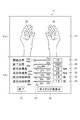
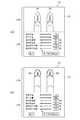
- FIG. 2 is a schematic diagram for explaining the display screen.
- a display screen 21 shown in FIG. 2 is a screen displayed on the head mounted display 2 and the display unit 7c.
- the display screen 21 includes an image part 21a and a dialog part 21b.
- a moving image 23 in which an image 22 of a hand as an object moves is displayed on the image portion 21a. This embodiment is an example of training of a patient 3 who has lost the hand 3c.
- the hand 3c is shifted from a state in which the hand 3c is opened to a state in which the hand 3c is gripped. Displays the video when transitioning to an open state.
- the state where the hand 3c is opened is the first state
- the state where the hand 3c is held is the second state. Transition from the first state to the second state is referred to as forward transition, and transition from the second state to the first state is referred to as backward transition.
- a time for stopping the movement of the hand image 22 is provided between the backward movement operation and the forward movement operation. Stopping the movement of the hand image 22 at this time is referred to as forward standby, and the standby time is defined as the forward standby time.
- a time during which the movement of the hand image 22 stops is provided between the forward movement operation and the backward movement operation. Stopping the movement of the hand image 22 at this time is referred to as reverse standby, and the standby time is defined as reverse standby time. Accordingly, the movement of the hand image 22 in the moving image 23 is performed in the order of forward transition, backward standby, backward transition, and forward standby. Then, after the forward standby, the process is repeated again from the forward transition.
- the dialog unit 21b is a screen for inputting and setting display conditions for the patient 3 or an assistant to reproduce the moving image 23.
- a start position input unit 24 is installed on the upper side in the drawing of the dialog unit 21b.
- the start position input unit 24 can set a frame that is an image used as the first state among frames that are images included in the moving image.
- a guide line 24a extends in the horizontal direction in the figure, and the position indication mark 24b can move along the guide line 24a.
- a pointer 25 is displayed in the dialog part 21b.
- the pointer 25 is an arrow-shaped mark. The patient 3 and the assistant can move the pointer 25 by touching and moving the touch panel 7b with a finger.
- the patient 3 and the assistant move the pointer 25 and overlap the pointer 25 with the position indication mark 24b.
- the start position input unit 24 can input.
- the position indication mark 24b can be moved to the left and right in conjunction with the movement of the pointer 25.
- the pointer 25 moves left and right, the image displayed on the image portion 21a is switched corresponding to the position of the position indication mark 24b.
- the position indication mark 24b When moving the position indication mark 24b to the left end of the guide line 24a, the first image of the captured moving image is displayed on the image portion 21a.
- the position indication mark 24b When the position indication mark 24b is moved to the right end of the guide line 24a, the last image of the captured moving image is displayed on the image portion 21a.
- the patient 3 and the assistant move the position indication mark 24b, the image displayed on the image portion 21a is switched.
- the patient 3 and the assistant select the first state by looking at the screen displayed on the image unit 21a.
- the patient 3 and the assistant tap the touch panel 7b with a finger after selecting the first state.
- the position instruction mark 24b does not move, and the image in the first state is determined.
- a start position column 24c is installed on the right side of the guide line 24a.
- the frame number of the screen indicated by the position indication mark 24b is displayed.
- the number 1 is displayed in the start position column 24c.
- the position indication mark 24b is at the right end of the guide line 24a, a number corresponding to the last frame number of the captured moving image is displayed in the start position column 24c.
- the position indication mark 24b is moved, a number corresponding to the position of the position indication mark 24b is displayed in the start position column 24c.
- the end position input unit 26 is installed below the start position input unit 24 in the figure.
- the end position input unit 26 can set a frame that is an image used as the second state among frames that are images included in the moving image.
- a guide line 26a extends in the horizontal direction in the figure, and the position instruction mark 26b can move along the guide line 26a.
- the patient 3 and the assistant can move the position indicating mark 26 b using the pointer 25.
- the image displayed on the image unit 21a is switched when the patient 3 and the assistant move the position of the position instruction mark 26b.
- the patient 3 and the assistant see the image displayed on the image unit 21a and select a frame to be used as the second state.
- the patient 3 and the assistant tap the touch panel 7b with a finger after selecting the second state.
- the position indicating mark 26b does not move and the second state is determined.
- An end position column 26c is provided on the right side of the guide line 26a in the drawing. In the end position column 26c, the frame number of the screen indicated by the position instruction mark 26b is displayed. When the position indication mark 26b is moved, a number corresponding to the position of the position indication mark 26b is displayed in the end position column 26c.
- a forward speed input unit 27 as a display condition setting unit is installed on the lower side of the end position input unit 26 in the figure.
- the forward speed input unit 27 can set the playback speed of the moving image 23 in the forward direction.
- a guide line 27a is installed extending in the horizontal direction in the figure, and the speed instruction mark 27b can move along the guide line 27a.
- the patient 3 and the assistant can move the speed instruction mark 27 b using the pointer 25.
- a forward speed column 27c is installed on the right side of the guide line 27a in the figure.
- the playback speed of the moving image 23 indicated by the speed instruction mark 27b is displayed.
- the speed instruction mark 27b is moved, the speed corresponding to the position of the speed instruction mark 27b is displayed in the forward speed column 27c.
- the unit of the playback speed of the moving image 23 is fps (frame per second).
- the recording speed of the moving image 23 taken by the camera 4 is 300 fps.
- the playback speed that can be instructed by the forward speed input unit 27 is 1 to 300 fps. When the playback speed is set to 10 fps, playback is performed at 1/10 the recording speed.
- the phantom limb pain treatment support apparatus 1 can reproduce the movement of the hand 3c in the forward direction at a low speed.
- the patient 3 and the assistant tap the touch panel 7b with a finger after selecting the reproduction speed for forward movement. Thereby, the speed instruction mark 27b does not move, and the reproduction speed for forward movement is determined.
- a reverse speed input section 28 as a display condition setting section is installed on the lower side of the forward speed input section 27 in the figure.
- the reverse speed input unit 28 can set the playback speed of the moving image 23 in the reverse direction.
- a guide line 28a extends in the horizontal direction in the figure, and the speed instruction mark 28b can move along the guide line 28a.
- the patient 3 and the assistant can move the speed instruction mark 28 b using the pointer 25.
- the reverse speed column 28c is installed on the right side of the guide line 28a.
- the reverse speed column 28c displays the playback speed of the moving image 23 indicated by the speed instruction mark 28b.
- the speed instruction mark 28b is moved, the speed corresponding to the position of the speed instruction mark 28b is displayed in the reverse speed field 28c.
- the playback speed that can be instructed by the reverse speed input unit 28 is 1 to 300 fps. Therefore, the phantom limb pain treatment support apparatus 1 can reproduce the movement of the hand 3c in the reverse direction at a low speed.
- the patient 3 and the assistant tap the touch panel 7b with a finger after selecting the reproduction speed for the reverse direction transition. As a result, the speed instruction mark 28b does not move, and the playback speed for the backward movement is determined.
- a forward standby time input unit 29 is installed on the lower side of the reverse speed input unit 28 in the figure.
- the forward standby time input unit 29 can set the forward standby time.
- a guide line 29a extends in the horizontal direction in the figure, and the time indication mark 29b can move along the guide line 29a.
- the patient 3 and the assistant can move the time indication mark 29 b using the pointer 25.
- a forward standby time column 29c is provided on the right side of the guide line 29a in the figure.
- the time indicated by the time instruction mark 29b is displayed in the forward standby time column 29c.
- a time corresponding to the position of the time indication mark 29b is displayed.
- the time that can be instructed by the forward standby time input unit 29 is 0.1 to 10 seconds. Therefore, the phantom limb pain treatment support apparatus 1 can prepare with sufficient margin in the preparation time when changing the movement of the hand 3c from the backward direction transition to the forward direction transition.
- the patient 3 and the assistant tap the touch panel 7b with a finger after setting the forward standby time. Thereby, the time indication mark 29b does not move, and the forward standby time is determined.
- a reverse standby time input unit 30 is installed on the lower side of the forward standby time input unit 29 in the figure.
- the backward standby time input unit 30 can set the backward standby time.
- a guide line 30a is installed extending in the horizontal direction in the figure, and the time indication mark 30b can be moved along the guide line 30a.
- the patient 3 and the assistant can move the time indication mark 30 b using the pointer 25.
- the reverse waiting time column 30c is installed on the right side of the guide line 30a.
- the time indicated by the time indication mark 30b is displayed in the reverse direction standby time column 30c.
- a time corresponding to the position of the time indication mark 30b is displayed.
- the time that can be instructed by the backward waiting time input unit 30 is 0.1 to 10 seconds. Therefore, the phantom limb pain treatment support apparatus 1 can prepare with sufficient margin in the preparation time when changing the movement of the hand 3c from the forward shift to the reverse shift.
- the patient 3 and the assistant tap the touch panel 7b with a finger after setting the reverse waiting time. As a result, the time indication mark 30b does not move and the backward standby time is determined.
- the end mark 31 and the dialog non-display mark 32 are installed on the lower side of the reverse waiting time input unit 30 in the figure.
- the operation of the phantom limb pain treatment support device 1 can be stopped.
- the pointer 25 is aligned with the dialog non-display mark 32 and the touch panel 7b is tapped with a finger, the display of the dialog part 21b is stopped and the area of the image part 21a can be increased.
- Activation of the phantom limb pain treatment support apparatus 1 and redisplay of the dialog part 21b can be performed by operating the input key 7a.
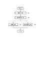
- FIG. 3 is a flowchart of the phantom limb pain treatment method
- FIGS. 4 to 7 are diagrams for explaining the phantom limb pain treatment method.
- step S1 corresponds to a photographing process.
- the patient 3 changes the shape of the healthy hand 3c from an open state to a grasped state.
- step S2 is a moving image forming process. This step is a step of editing the photographed moving image 23 to form a training moving image 23.
- the process proceeds to step S3 and step S4. Steps S3 and S4 are performed in parallel.
- Step S3 is a training process. This step is a step in which the patient 3 thinks of moving the hand 3c of the missing person by looking at the moving image 23.
- Step S4 is a condition adjustment process. This step is a step of changing the range in which the moving image 23 is repeatedly played, the playback speed, the forward standby time, and the backward standby time. When finishing step S3, the phantom limb pain treatment is finished.
- FIG. 4 is a diagram corresponding to the photographing process in step S1.
- imaging is performed by gradually changing the shape of the patient 3 from the opened state to the grasped state.
- An image obtained by photographing the hand 3c shown in FIG. 4A is a first image
- an image obtained by photographing the hand 3c shown in FIG. 4B is a second image.
- An image obtained by photographing the hand 3c illustrated in FIG. 4D is referred to as a third image
- an image obtained by photographing the hand 3c illustrated in FIG. 4D is referred to as a fourth image.
- An image obtained by photographing the hand 3c shown in FIG. 4E is a fifth image
- an image obtained by photographing the hand 3c shown in FIG. 4F is a sixth image.
- An image obtained by photographing the hand 3c illustrated in FIG. 4G is referred to as a seventh image
- An image obtained by photographing the hand 3c shown in FIG. 4 (i) is referred to as a ninth image
- an image obtained by photographing the hand 3c shown in FIG. 4 (j) is referred to as a tenth image.
- the first image to the tenth image are continuous images. Each image is shot at a shooting speed of 300 fps, so that it is shot at a higher speed than a normal camera. Therefore, if the playback speed is lower than 300 fps, playback can be performed at a lower speed that is slower than the speed at which the image was taken.
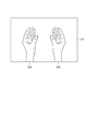
- FIG. 5 is a diagram corresponding to the moving image forming process of step S2.
- the left hand image 22a is inverted in the left-right direction to form a right hand image 22b.
- the left hand image 22a and the right hand image 22b are arranged side by side.
- a continuous forward moving image 23a is formed in which this image continues from the first image to the tenth image.
- the forward moving image 23a is a moving image 23 that changes from an image 22 of a hand that opens the hand 3c to an image 22 of the hand that holds the hand 3c.
- a backward moving image 23b is formed by reversely reproducing the forward moving image 23a.
- the reverse direction moving image 23b is a moving image 23 that changes from the image 22 of the hand holding the hand 3c to the image 22 of the hand opening the hand 3c.
- FIG. 6 and 7 are diagrams corresponding to the training process in step S3 and the condition adjustment process in step S4.
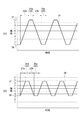
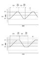
- FIG. 6A to FIG. 7B are time charts showing the progress of the moving image 23.
- the vertical axis indicates the screen number on which the moving image 23 is projected, and the horizontal axis indicates the transition of time. Time shifts from the left side to the right side in the figure.
- step S ⁇ b> 3 the phantom limb pain treatment support apparatus 1 reproduces the moving image 23. Then, the patient 3 sees the moving image 23 and thinks to open and close the hand 3c in synchronization with the image 22 of the hand.
- the patient 3 lacks the right hand 3c, so the right hand 3c cannot be physically opened and closed, but imagines that the hand 3c is opened and closed in the brain.
- the left hand 3c is preferably opened and closed in accordance with the moving image 23. Thereby, it becomes easy to feel that the right hand 3c is also opened and closed synchronously.
- the first transition line 33 in FIG. 6A indicates the progress of the moving image 23.
- the forward moving image 23a from the first image to the tenth image is reproduced.
- the patient 3 considers moving from the open state of the hand 3c to the gripped state while watching the moving image 23.
- the backward standby 34 is performed as the backward standby state.
- the moving image 23 stops for the reverse standby time 34a. During this time, patient 3 prepares for a reverse transition.
- the phantom limb pain treatment support apparatus 1 After the backward waiting 34, the phantom limb pain treatment support apparatus 1 reproduces the backward moving image 23b from the tenth image to the first image. At this time, the patient 3 thinks that it will open from the state which grasped the hand 3c. Then, after the phantom limb pain treatment support apparatus 1 reproduces the backward moving image 23b, the forward standby 35 as the forward standby state is performed. In the forward standby 35, the moving image 23 stops for the forward standby time 35a. During this time, patient 3 prepares for a forward transition. The training is performed by repeating the above contents.
- the state of the hand 3c indicated by the screen when starting the forward moving image 23a is referred to as a first state 36. Then, the state of the hand 3c indicated by the screen when the forward moving image 23a is ended is referred to as a second state 37.
- step S ⁇ b> 3 the patient 3 performs a repetitive operation of moving the hand 3 c between the first state 36 and the second state 37.
- the first state 36 is the state indicated by the first image
- the second state 37 is the state indicated by the tenth image.
- the first state 36 is a state where the patient 3 opens the hand 3c.
- the patient 3 puts the hand 3c into the second state 37 while watching the forward moving image 23a. That is, the patient 3 changes the hand 3c from the opened state to the held state.
- the patient 3 performs the backward waiting 34 during the backward waiting time 34a. During this time, the patient 3 keeps holding the hand 3c. Then, the patient 3 prepares to open the hand 3c.
- the hand 3c is in the second state 37.
- the second state 37 is a state where the patient 3 holds the hand 3c.
- the patient 3 puts the hand 3c into the first state 36 while watching the backward moving image 23b. That is, the patient 3 is opened from the state in which the hand 3c is held.
- the patient 3 performs the forward standby 35 during the forward standby time 35a. During this time, the patient 3 keeps the hand 3c open. Then, the patient 3 prepares to hold the hand 3c.
- training while watching the forward moving image 23a and training while watching the backward moving image 23b are repeatedly performed.
- the phantom limb pain treatment support apparatus 1 can interrupt the training process of step S3 and perform the condition adjustment process of step S4.
- step S3 Next, the example which changed the 1st state 36 and the 2nd state 37 of the moving image 23 is shown.
- the patient 3 or the assistant moves the position instruction mark 24b indicating the start position from the position indicating the first image to the position indicating the image between the third image and the fourth image. Further, the patient 3 or the assistant moves the position instruction mark 26b indicating the end position from the position indicating the tenth image to the position indicating the image between the eighth image and the ninth image. And the training process of step S3 is restarted.
- step S ⁇ b> 3 the moving image transmission unit 18 outputs the moving image data in which the first state 36 and the second state 37 are changed to the head mounted display 2.
- the head mounted display 2 displays the moving image 23 in which the first state 36 and the second state 37 are changed.
- the moving image transmitting unit 18 does not change the moving image data 13 and reproduces only the reproduction condition.
- the second transition line 38 in FIG. 6B shows the progress of the moving image 23.
- the forward moving image 23a starts from an image between the third image and the fourth image, and is reproduced up to an image between the eighth image and the ninth image.
- the patient 3 thinks that the hand 3c is slightly held from the slightly opened state.
- the backward moving image 23b is reproduced through the backward standby 34.
- the backward moving image 23b starts from an image between the eighth image and the ninth image, and is reproduced up to an image between the third image and the fourth image.
- the forward moving image 23a is reproduced through the forward standby 35.
- the training is performed by repeating the above contents.
- the first state 36 and the second state 37 are adjusted, and training is performed by setting the moving image 23 indicating a state in which the patient 3 can easily think. Further, when the user gets used to training, the first state 36 and the second state 37 are adjusted and the moving image 23 showing a state in which the patient 3 can easily think is set for training. Thereby, training can be performed efficiently.
- step S3 an example is shown in which the forward speed, which is the speed at which the forward moving picture 23a of the moving picture 23 is played, and the reverse speed, which is the speed at which the backward moving picture 23b is played, are changed.
- the patient 3 or the assistant moves the speed instruction mark 27b of the forward speed input unit 27 indicating the forward speed.
- the speed instruction mark 27b is moved to decrease the number in the forward speed column 27c.
- the patient 3 or the assistant moves the speed instruction mark 28b of the reverse speed input unit 28 indicating the reverse speed.
- the speed instruction mark 28b is moved to decrease the number in the reverse speed column 28c.
- the training process of step S3 is restarted.
- step S ⁇ b> 3 the moving image transmission unit 18 outputs the moving image data in which the forward speed and the reverse speed are changed to the head mounted display 2.
- the head mounted display 2 displays a moving image 23 in which the forward speed and the reverse speed are changed.
- the moving image transmitting unit 18 does not change the moving image data 13 and reproduces only the reproduction condition.
- the third transition line 41 in FIG. 7A shows the progress of the moving image 23.
- the playback time of the forward moving image 23a is longer than the playback time of the forward moving image 23a indicated by the second transition line 38. Therefore, the forward speed is slow in the third transition line 41.
- the playback time of the backward moving image 23b is longer than the playback time of the backward moving image 23b indicated by the second transition line 38. Therefore, the reverse speed is slow in the third transition line 41.
- the patient 3 or the assistant moves the time indication mark 29b of the forward standby time input unit 29 indicating the forward standby time 35a.
- the time indication mark 29b is moved to increase the number in the forward standby time column 29c.
- the patient 3 or the assistant moves the time indication mark 30b of the reverse direction standby time input unit 30 indicating the reverse direction standby time 34a.
- the time indication mark 30b is moved to increase the number in the backward waiting time column 30c.
- the training process of step S3 is restarted.
- step S ⁇ b> 3 the moving image transmission unit 18 outputs the moving image data in which the forward waiting time 35 a and the backward waiting time 34 a are changed to the head mounted display 2.
- the head mounted display 2 displays the moving image 23 in which the forward standby time 35a and the backward standby time 34a are changed.
- the moving image transmitting unit 18 does not change the moving image data 13 and reproduces only the reproduction condition.
- the fourth transition line 42 in FIG. 7B indicates the progress of the moving image 23.
- the backward waiting time 34 a is longer than the backward waiting time 34 a indicated by the third transition line 41. Therefore, in the fourth transition line 42, the time from the end of the forward moving image 23a to the start of the backward moving image 23b is longer.
- the forward standby time 35a is longer than the forward standby time 35a indicated by the third transition line 41. Accordingly, in the fourth transition line 42, the time from the end of the backward moving image 23b to the start of the forward moving image 23a is longer.
- the forward waiting time 35a and the backward waiting time 34a are short.
- the forward standby time 35a and the backward standby time 34a are lengthened. Then, the patient 3 is trained so that the patient 3 can easily prepare for thinking during the waiting time. Also, when getting used to the training, the forward waiting time 35a and the backward waiting time 34a are shortened to set the moving image 23 in a state in which the patient 3 can easily think. Thereby, training can be performed efficiently.
- the moving image transmission unit 18 outputs the moving image data to the head mounted display 2, and the head mounted display 2 displays the moving image 23 based on the moving image data.
- the hand 3c repeatedly displays the images from the first state 36 to the second state 37.
- the patient 3 looks at the moving image 23 and sees the hand 3c and the image 22 of the hand of the moving image 23 in an overlapping manner. Then, the patient 3 thinks that his / her hand 3 c repeatedly moves between the first state 36 and the second state 37. This training can reduce pain in the hand 3c that has been lost.
- the phantom limb pain treatment support apparatus 1 of this embodiment includes a forward speed input unit 27 for inputting a forward speed and a reverse speed input unit 28 for inputting a reverse speed. Since the moving image data 13 is displayed under display conditions without being edited, time for editing the moving image data 13 is not required. Accordingly, since a moving image in which the forward speed and the reverse speed are changed to a speed suitable for the patient's condition can be displayed, training can be performed efficiently.
- the phantom limb pain treatment support apparatus 1 waits for the forward standby time 35a in the forward standby 35. Furthermore, the phantom limb pain treatment support apparatus 1 stands by for the backward waiting time 34a in the backward waiting 34.
- the forward waiting time 35a the patient 3 prepares to switch his thoughts from the backward transition to the forward transition.
- the backward waiting time 34a the patient 3 prepares to switch his mind from forward shift to reverse shift. Since the forward waiting time 35a and the backward waiting time 34a change appropriately depending on the physical condition of the patient 3, it is preferable to adjust each time the training is performed.
- the phantom limb pain support apparatus 1 of this embodiment can adjust a moving image by inputting the forward standby time 35a and the backward standby time 34a in the display condition input unit 16. Therefore, since a moving image in which the forward standby time 35a and the backward standby time 34a are changed to speeds suitable for the state of the patient 3 can be displayed, training can be performed efficiently.
- the display condition of the repetitive operation includes an image corresponding to the first state 36 and an image corresponding to the second state 37 in the moving image 23.
- images in a plurality of states change.
- the phantom limb pain treatment support apparatus 1 can input the first state 36 and the second state 37 through the display condition input unit 16 to adjust the moving image. Therefore, since the screen of the first state 36 and the screen of the second state 37 can be changed and displayed each time on the moving image 23 suitable for the state of the patient 3, training can be performed efficiently.
- the part for displaying the moving image 23 is the head mounted display 2, which is used by being installed on the head 3 a of the patient 3. Therefore, the patient 3 can move the place where the moving image 23 is displayed by moving the neck. For this reason, it is possible to match the moving image 23 to the body that is missing corresponding to the posture of the patient 3.
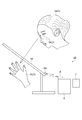
- the phantom limb pain treatment support device 45 includes a display device 46 as shown in FIG.
- the display device 46 is a flat panel display or a display having a curved surface, and a liquid crystal display or an OLED (Organic light-emitting diodes) display can be used as the display device 46.
- a communication unit 46 c is installed in the display device 46, and the communication unit 46 c can receive the data of the moving image 23 from the communication device 9.
- the display device 46 is disposed between the head 3a and the hand 3c of the patient 3. Then, the patient 3 can perform training to think about opening and closing the missing hand 3 c while viewing the moving image 23 displayed on the display device 46. Also at this time, the patient 3 or the assistant can input the display condition of the moving image 23 using the input / output terminal 7, and can easily change the reproduction condition each time to view the moving image 23.
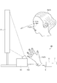
- the phantom limb pain treatment support device 49 includes a projector 50 and a screen 51 as shown in FIG.
- a communication unit 50 c is installed in the projector 50, and the communication unit 50 c can receive the data of the moving image 23 from the communication device 9.
- the screen 51 is installed in front of the patient 3. Then, the patient 3 can perform training to think about opening and closing the missing hand 3c while watching the moving image 23 displayed on the screen 51. Also at this time, the patient 3 or the assistant can input the display condition of the moving image 23 using the input / output terminal 7, and can easily change the reproduction condition each time to view the moving image 23.
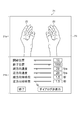
- the moving image 23 is displayed on the image portion 21a as shown in FIG.
- This moving image 23 displays an image 22 of a healthy person's hand.
- photographing is performed in a state where a healthy person opens and closes the hand 3c.
- the training process of step S3 the patient 3 observes the moving image 23 in which the healthy person opens and closes the hand 3c, and performs training. Therefore, even when the patient 3 lacks both the left and right hands 3c, training can be performed using the phantom limb pain treatment support apparatus 1.
- the assistant inputs the display condition of the moving image 23 using the input / output terminal 7, and the patient 3 can change the reproduction condition and watch the moving image 23 each time.
- the moving image 23 is displayed on the image portion 21a as shown in FIG.
- a foot image 54 is displayed in the moving image 23.
- the screen of the moving image 23 in FIG. 11A shows a state where a person is sitting on a chair, bending his knees and lowering his legs.
- the screen of the moving image 23 in FIG. 11B shows a state where a person sits on a chair, stretches his knees and raises his leg.
- step S1 imaging of an operation in which the patient 3 sits on a chair and moves his / her foot up and down is performed.
- step S2 a symmetrical mirror image moving image is formed.
- step S3 the patient 3 observes the moving image 23 which is moving the leg up and down and performs training. Therefore, training can be performed using the phantom limb pain treatment support apparatus 1 when the patient 3 lacks one leg.
- the patient 3 or the assistant inputs the display condition of the moving image 23 using the input / output terminal 7, and the patient 3 can easily change the reproduction condition each time and view the moving image 23.
- Modification 1 In the first embodiment, the moving image 23 in which the left and right hand images 22 move in the same manner is used. The right side and the left side may be moved differently. A moving image 23 in which left and right hand images 22 are alternately opened and closed may be used. The moving image 23 can be easily trained by the patient 3.
- Mode 2 In the first embodiment, the display condition of the moving image 23 is input by looking at the screen displayed in the dialog unit 21b.
- An operation unit such as a rotating dial or a sliding knob may be attached to the input / output terminal 7 so that display conditions can be input. The operation unit can be operated as if touched without looking at the operation unit.
- Modification 3 In the first embodiment, a planar image is displayed on the head mounted display 2. A stereoscopic image may be displayed on the head mounted display 2. This makes it easy to feel that the patient 3 is actually moving the hand 3c.
- the control device 5 is not connected to an external device.
- the control device 5 may be connected to the server via the communication device 9 and a network.
- the server stores a plurality of setting data 14 when the patient 3 drives the phantom limb pain treatment support apparatus 1.
- the setting data 14 may be transferred from the server.
- the previous setting data 14 can be utilized even if different apparatuses are used.
- FIG. 5 (Modification 5)
- the pain treatment of the hand 3c was performed using the phantom limb pain treatment assistance apparatus 1.
- FIG. The phantom limb pain treatment support device 1 may be used to perform finger pain treatment or rehabilitation.
- the moving image 23 in which the finger moves it can be performed in the same manner as in the first embodiment.
- the patient 3 or an assistant inputs the display condition of the moving image 23 using the input / output terminal 7, and the patient 3 can change the reproduction condition and watch the moving image 23 each time.
- it can be used in various cases such as elbows and ankles of feet.
- the mirror 2a is a non-transmissive mirror.
- the mirror part 2a may be a transmissive type.
- the moving image forming unit 17 forms a moving image so that the hand 3c seen through the mirror 2a and the moving hand image 22 appear to overlap each other. Thereby, the patient 3 can feel as if the paralyzed hand 3c moves.
- a cover may be attached to the mirror part 2a to switch between the transmission type and the non-transmission type. It is possible to select the one that is easy to experience so that the hand 3c moves.
- the phantom limb pain treatment support apparatus 1 is used for pain treatment to move the deficient hand 3c.
- it may be used for rehabilitation of a body that has been damaged by nerves or brain and has become difficult to move.
- the nervous system can be trained by moving the body that is difficult to move by watching the video.
- the moving image 23 in which the hand image 22 moves as an object is displayed, but the moving image to be displayed is not limited to this.
- Other parts of the body may be used, and not only the photographed actual body but also a pseudo body by animation or the like may be displayed.
- not only the display similar to the body but also a completely different display may be displayed.
- a completely different one is not particularly limited, but is, for example, a book or a door. That is, it is only necessary that the patient can visually recognize or understand that the motion is similar to the repetitive motion of the body.
Landscapes
- Health & Medical Sciences (AREA)
- Engineering & Computer Science (AREA)
- Public Health (AREA)
- General Health & Medical Sciences (AREA)
- Epidemiology (AREA)
- Medical Informatics (AREA)
- Primary Health Care (AREA)
- Theoretical Computer Science (AREA)
- Physics & Mathematics (AREA)
- Psychology (AREA)
- Life Sciences & Earth Sciences (AREA)
- General Physics & Mathematics (AREA)
- General Engineering & Computer Science (AREA)
- Child & Adolescent Psychology (AREA)
- Developmental Disabilities (AREA)
- Hospice & Palliative Care (AREA)
- Psychiatry (AREA)
- Physical Education & Sports Medicine (AREA)
- Social Psychology (AREA)
- Biophysics (AREA)
- Human Computer Interaction (AREA)
- Acoustics & Sound (AREA)
- Anesthesiology (AREA)
- Biomedical Technology (AREA)
- Heart & Thoracic Surgery (AREA)
- Hematology (AREA)
- Animal Behavior & Ethology (AREA)
- Veterinary Medicine (AREA)
- Rehabilitation Tools (AREA)
- Controls And Circuits For Display Device (AREA)
Priority Applications (3)
| Application Number | Priority Date | Filing Date | Title |
|---|---|---|---|
| US15/552,420 US20180036506A1 (en) | 2015-02-24 | 2016-01-26 | Display device, display method, and non-transitory computer-readable medium |
| CN201680011229.2A CN107251548A (zh) | 2015-02-24 | 2016-01-26 | 显示装置、显示方法和程序 |
| EP16754894.0A EP3264747A4 (en) | 2015-02-24 | 2016-01-26 | Display device, display method and program |
Applications Claiming Priority (2)
| Application Number | Priority Date | Filing Date | Title |
|---|---|---|---|
| JP2015-033743 | 2015-02-24 | ||
| JP2015033743A JP2016158056A (ja) | 2015-02-24 | 2015-02-24 | 表示装置、表示方法およびプログラム |
Publications (1)
| Publication Number | Publication Date |
|---|---|
| WO2016136137A1 true WO2016136137A1 (ja) | 2016-09-01 |
Family
ID=56789205
Family Applications (1)
| Application Number | Title | Priority Date | Filing Date |
|---|---|---|---|
| PCT/JP2016/000366 Ceased WO2016136137A1 (ja) | 2015-02-24 | 2016-01-26 | 表示装置、表示方法およびプログラム |
Country Status (5)
| Country | Link |
|---|---|
| US (1) | US20180036506A1 (cg-RX-API-DMAC7.html) |
| EP (1) | EP3264747A4 (cg-RX-API-DMAC7.html) |
| JP (1) | JP2016158056A (cg-RX-API-DMAC7.html) |
| CN (1) | CN107251548A (cg-RX-API-DMAC7.html) |
| WO (1) | WO2016136137A1 (cg-RX-API-DMAC7.html) |
Cited By (2)
| Publication number | Priority date | Publication date | Assignee | Title |
|---|---|---|---|---|
| CN107875616A (zh) * | 2016-09-30 | 2018-04-06 | 精工爱普生株式会社 | 运动训练装置、记录介质、显示方法 |
| EP3373305A1 (en) * | 2017-03-10 | 2018-09-12 | Seiko Epson Corporation | Training device usable for rehabilitation and computer program for training device usable for rehabilitation |
Families Citing this family (1)
| Publication number | Priority date | Publication date | Assignee | Title |
|---|---|---|---|---|
| JP7659309B2 (ja) * | 2021-07-20 | 2025-04-09 | 国立大学法人東北大学 | 分析装置、分析方法、分析プログラム、及び、生成装置 |
Citations (2)
| Publication number | Priority date | Publication date | Assignee | Title |
|---|---|---|---|---|
| JP2003046903A (ja) * | 2001-07-31 | 2003-02-14 | Sanyo Electric Co Ltd | 表示装置 |
| JP2005266171A (ja) * | 2004-03-17 | 2005-09-29 | Scalar Corp | 疲労回復支援装置 |
Family Cites Families (4)
| Publication number | Priority date | Publication date | Assignee | Title |
|---|---|---|---|---|
| JP2004271805A (ja) * | 2003-03-07 | 2004-09-30 | Mitsubishi Electric Corp | 焦点調節誘導方法 |
| EP2186326A1 (en) * | 2007-09-10 | 2010-05-19 | Thomson Licensing | Video playback |
| CN101234224A (zh) * | 2008-01-29 | 2008-08-06 | 河海大学 | 一种利用虚拟现实技术帮助用户进行训练康复的方法 |
| US8911343B2 (en) * | 2012-10-20 | 2014-12-16 | Pieter C Wiest | System and method utilizing a smart phone for alleviating phantom limb discomfort |
-
2015
- 2015-02-24 JP JP2015033743A patent/JP2016158056A/ja not_active Withdrawn
-
2016
- 2016-01-26 EP EP16754894.0A patent/EP3264747A4/en not_active Withdrawn
- 2016-01-26 CN CN201680011229.2A patent/CN107251548A/zh active Pending
- 2016-01-26 US US15/552,420 patent/US20180036506A1/en not_active Abandoned
- 2016-01-26 WO PCT/JP2016/000366 patent/WO2016136137A1/ja not_active Ceased
Patent Citations (2)
| Publication number | Priority date | Publication date | Assignee | Title |
|---|---|---|---|---|
| JP2003046903A (ja) * | 2001-07-31 | 2003-02-14 | Sanyo Electric Co Ltd | 表示装置 |
| JP2005266171A (ja) * | 2004-03-17 | 2005-09-29 | Scalar Corp | 疲労回復支援装置 |
Non-Patent Citations (1)
| Title |
|---|
| See also references of EP3264747A4 * |
Cited By (3)
| Publication number | Priority date | Publication date | Assignee | Title |
|---|---|---|---|---|
| CN107875616A (zh) * | 2016-09-30 | 2018-04-06 | 精工爱普生株式会社 | 运动训练装置、记录介质、显示方法 |
| EP3373305A1 (en) * | 2017-03-10 | 2018-09-12 | Seiko Epson Corporation | Training device usable for rehabilitation and computer program for training device usable for rehabilitation |
| CN108568085A (zh) * | 2017-03-10 | 2018-09-25 | 精工爱普生株式会社 | 能够用于康复的训练装置、其控制部以及记录介质 |
Also Published As
| Publication number | Publication date |
|---|---|
| EP3264747A1 (en) | 2018-01-03 |
| EP3264747A4 (en) | 2018-12-05 |
| CN107251548A (zh) | 2017-10-13 |
| JP2016158056A (ja) | 2016-09-01 |
| US20180036506A1 (en) | 2018-02-08 |
Similar Documents
| Publication | Publication Date | Title |
|---|---|---|
| JP6565212B2 (ja) | 表示装置、表示方法およびプログラム | |
| US20230094522A1 (en) | Devices, methods, and graphical user interfaces for content applications | |
| KR102925689B1 (ko) | 라이브 통신 세션들을 관리하기 위한 사용자 인터페이스들 | |
| US9838597B2 (en) | Imaging device, imaging method, and program | |
| CN119512362A (zh) | 用于显示与媒体内容相关的用户界面元素的方法 | |
| JP2022546502A (ja) | 三次元環境と相互作用するためのデバイス、方法、及びグラフィカルユーザインタフェース | |
| US12620184B2 (en) | Devices, methods, and graphical user interfaces for interacting with three-dimensional environments | |
| KR20240167090A (ko) | 사용자의 표현을 생성 및 디스플레이하기 위한 디바이스들, 방법들, 및 그래픽 사용자 인터페이스들 | |
| CN102880289A (zh) | 检测眼球注视点可实现视频播放和暂停的控制系统及方法 | |
| JP2015039522A (ja) | リハビリ装置および幻肢痛治療支援装置 | |
| JP2016158056A (ja) | 表示装置、表示方法およびプログラム | |
| CN107665070A (zh) | 显示装置、显示控制方法以及存储介质 | |
| CN105717994A (zh) | 穿戴式智能设备 | |
| JP2016513991A (ja) | ハプティックアクチュエータ制御パラメータを有するオーディオビジュアルコンテンツのアイテムを再生するための方法、および方法を実施するデバイス | |
| WO2012063595A1 (ja) | 立体画像表示装置、立体画像表示方法、立体画像表示方法をコンピュータに実行させるためのプログラム、及びそのプログラムを記録した記録媒体 | |
| KR20250049408A (ko) | 3차원 환경들과의 상호작용을 위한 디바이스들, 방법들 및 그래픽 사용자 인터페이스들 | |
| CN205540445U (zh) | 穿戴式智能设备 | |
| CN118963605A (zh) | 用于捕获和显示媒体的设备、方法和图形用户界面 | |
| JP2012257252A (ja) | 立体画像表示装置、立体画像表示方法、立体画像表示方法をコンピュータに実行させるためのプログラム、及びそのプログラムを記録した記録媒体 | |
| JP2012065111A (ja) | 立体画像表示装置、立体画像表示方法、立体画像表示方法をコンピュータに実行させるためのプログラム、及びそのプログラムを記録した記録媒体 | |
| CN114040231B (zh) | 一种vr视频播放系统、方法及vr眼镜 | |
| JP7218872B2 (ja) | アニメーション制作システム | |
| CN107688421A (zh) | 一种在触控设备上显示3d界面的控制方法和系统 | |
| KR20250050092A (ko) | 시선 추적 등록을 위한 사용자 인터페이스들 | |
| JP2019097640A (ja) | 訓練補助装置およびプログラム |
Legal Events
| Date | Code | Title | Description |
|---|---|---|---|
| 121 | Ep: the epo has been informed by wipo that ep was designated in this application |
Ref document number: 16754894 Country of ref document: EP Kind code of ref document: A1 |
|
| WWE | Wipo information: entry into national phase |
Ref document number: 15552420 Country of ref document: US |
|
| NENP | Non-entry into the national phase |
Ref country code: DE |
|
| REEP | Request for entry into the european phase |
Ref document number: 2016754894 Country of ref document: EP |