WO2016133123A1 - Équipement d'utilisateur et procédé de commutation de transmission en liaison montante - Google Patents
Équipement d'utilisateur et procédé de commutation de transmission en liaison montante Download PDFInfo
- Publication number
- WO2016133123A1 WO2016133123A1 PCT/JP2016/054581 JP2016054581W WO2016133123A1 WO 2016133123 A1 WO2016133123 A1 WO 2016133123A1 JP 2016054581 W JP2016054581 W JP 2016054581W WO 2016133123 A1 WO2016133123 A1 WO 2016133123A1
- Authority
- WO
- WIPO (PCT)
- Prior art keywords
- cell
- carrier
- switching
- transmission
- specific cell
- Prior art date
Links
- 230000005540 biological transmission Effects 0.000 title claims abstract description 126
- 238000000034 method Methods 0.000 title claims description 15
- 230000002776 aggregation Effects 0.000 claims abstract description 26
- 238000004220 aggregation Methods 0.000 claims abstract description 26
- 238000010295 mobile communication Methods 0.000 claims abstract description 15
- 230000007704 transition Effects 0.000 claims description 82
- 238000004891 communication Methods 0.000 claims description 24
- 239000000969 carrier Substances 0.000 claims description 9
- 230000001052 transient effect Effects 0.000 abstract description 3
- 238000012545 processing Methods 0.000 description 38
- 230000006870 function Effects 0.000 description 28
- 230000008054 signal transmission Effects 0.000 description 22
- 238000012986 modification Methods 0.000 description 17
- 230000004048 modification Effects 0.000 description 17
- 230000001360 synchronised effect Effects 0.000 description 14
- 241000700159 Rattus Species 0.000 description 11
- 238000010586 diagram Methods 0.000 description 11
- 238000006243 chemical reaction Methods 0.000 description 8
- 238000010187 selection method Methods 0.000 description 7
- 230000009977 dual effect Effects 0.000 description 5
- 230000008859 change Effects 0.000 description 4
- 238000005516 engineering process Methods 0.000 description 3
- 230000001960 triggered effect Effects 0.000 description 3
- 101000741965 Homo sapiens Inactive tyrosine-protein kinase PRAG1 Proteins 0.000 description 2
- 102100038659 Inactive tyrosine-protein kinase PRAG1 Human genes 0.000 description 2
- 230000002159 abnormal effect Effects 0.000 description 2
- 230000003321 amplification Effects 0.000 description 2
- 238000012790 confirmation Methods 0.000 description 2
- 238000003199 nucleic acid amplification method Methods 0.000 description 2
- 230000008569 process Effects 0.000 description 2
- 238000006467 substitution reaction Methods 0.000 description 2
- 239000008186 active pharmaceutical agent Substances 0.000 description 1
- 238000012217 deletion Methods 0.000 description 1
- 230000037430 deletion Effects 0.000 description 1
- 238000005259 measurement Methods 0.000 description 1
- 238000012544 monitoring process Methods 0.000 description 1
- 230000009467 reduction Effects 0.000 description 1
- 230000011664 signaling Effects 0.000 description 1
- 208000037918 transfusion-transmitted disease Diseases 0.000 description 1
Images


Classifications
-
- H—ELECTRICITY
- H04—ELECTRIC COMMUNICATION TECHNIQUE
- H04L—TRANSMISSION OF DIGITAL INFORMATION, e.g. TELEGRAPHIC COMMUNICATION
- H04L5/00—Arrangements affording multiple use of the transmission path
- H04L5/0001—Arrangements for dividing the transmission path
- H04L5/0003—Two-dimensional division
- H04L5/0005—Time-frequency
- H04L5/0007—Time-frequency the frequencies being orthogonal, e.g. OFDM(A), DMT
- H04L5/001—Time-frequency the frequencies being orthogonal, e.g. OFDM(A), DMT the frequencies being arranged in component carriers
-
- H—ELECTRICITY
- H04—ELECTRIC COMMUNICATION TECHNIQUE
- H04L—TRANSMISSION OF DIGITAL INFORMATION, e.g. TELEGRAPHIC COMMUNICATION
- H04L5/00—Arrangements affording multiple use of the transmission path
- H04L5/0091—Signaling for the administration of the divided path
- H04L5/0096—Indication of changes in allocation
- H04L5/0098—Signalling of the activation or deactivation of component carriers, subcarriers or frequency bands
-
- H—ELECTRICITY
- H04—ELECTRIC COMMUNICATION TECHNIQUE
- H04W—WIRELESS COMMUNICATION NETWORKS
- H04W16/00—Network planning, e.g. coverage or traffic planning tools; Network deployment, e.g. resource partitioning or cells structures
- H04W16/02—Resource partitioning among network components, e.g. reuse partitioning
- H04W16/12—Fixed resource partitioning
-
- H—ELECTRICITY
- H04—ELECTRIC COMMUNICATION TECHNIQUE
- H04W—WIRELESS COMMUNICATION NETWORKS
- H04W36/00—Hand-off or reselection arrangements
- H04W36/0005—Control or signalling for completing the hand-off
- H04W36/0055—Transmission or use of information for re-establishing the radio link
- H04W36/0064—Transmission or use of information for re-establishing the radio link of control information between different access points
-
- H—ELECTRICITY
- H04—ELECTRIC COMMUNICATION TECHNIQUE
- H04W—WIRELESS COMMUNICATION NETWORKS
- H04W72/00—Local resource management
- H04W72/04—Wireless resource allocation
- H04W72/044—Wireless resource allocation based on the type of the allocated resource
- H04W72/0446—Resources in time domain, e.g. slots or frames
-
- H—ELECTRICITY
- H04—ELECTRIC COMMUNICATION TECHNIQUE
- H04W—WIRELESS COMMUNICATION NETWORKS
- H04W36/00—Hand-off or reselection arrangements
- H04W36/0005—Control or signalling for completing the hand-off
- H04W36/0055—Transmission or use of information for re-establishing the radio link
- H04W36/0069—Transmission or use of information for re-establishing the radio link in case of dual connectivity, e.g. decoupled uplink/downlink
- H04W36/00692—Transmission or use of information for re-establishing the radio link in case of dual connectivity, e.g. decoupled uplink/downlink using simultaneous multiple data streams, e.g. cooperative multipoint [CoMP], carrier aggregation [CA] or multiple input multiple output [MIMO]
-
- H—ELECTRICITY
- H04—ELECTRIC COMMUNICATION TECHNIQUE
- H04W—WIRELESS COMMUNICATION NETWORKS
- H04W72/00—Local resource management
- H04W72/12—Wireless traffic scheduling
- H04W72/1263—Mapping of traffic onto schedule, e.g. scheduled allocation or multiplexing of flows
- H04W72/1268—Mapping of traffic onto schedule, e.g. scheduled allocation or multiplexing of flows of uplink data flows
-
- H—ELECTRICITY
- H04—ELECTRIC COMMUNICATION TECHNIQUE
- H04W—WIRELESS COMMUNICATION NETWORKS
- H04W76/00—Connection management
- H04W76/20—Manipulation of established connections
- H04W76/27—Transitions between radio resource control [RRC] states
Definitions
- the present invention relates to a technology in which a user apparatus in a mobile communication system supporting carrier aggregation switches uplink transmission between carriers.
- CA carrier aggregation
- CC component carrier
- a PCell Primary cell
- SCell Secondary cell
- the user apparatus UE can connect to the PCell and add an SCell as necessary.
- the PCell is a cell similar to a single cell that supports RLM (Radio Link Monitoring), SPS (Semi-Persistent Scheduling), and the like.
- the SCell is a cell that is in an inactive state (deactivated state), and thus can be communicated (schedulable) only when activated.
- RRC Radio Resource Control
- CA is performed using a plurality of CCs under the same base station eNB.
- Rel-12 Dual connectivity that realizes high throughput by performing simultaneous communication using CCs under different base stations eNB is introduced (Non-patent Document 1).
- the UE performs communication by simultaneously using radio resources of a plurality of physically different base stations eNB.
- DC Dual connectivity
- Inter eNB CA inter-base station carrier aggregation
- MeNB Master-eNB
- SeNB Secondary-eNB
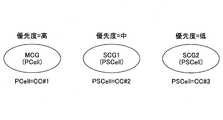
- a cell group composed of cells (one or more) under the MeNB is defined as MCG (Master Cell Group, master cell group), and a cell group composed of cells (one or a plurality) under the SeNB is defined as SCG ( (Secondary Cell Group, secondary cell group).
- MCG Master Cell Group, master cell group
- SCG Secondary Cell Group, secondary cell group
- the MCG has a PCell, and in addition, can have an SCell.
- the SCG includes one or a plurality of SCells, a UL CC is set in at least one SCell of the SCGs, and a PUCCH (physical uplink control channel) is set in one of them. This SCell is referred to as PSCell (primary SCell).
- the user equipment UE Since DC introduced in Rel-12 feeds back MAC-ACK / NACK independently to a plurality of eNBs, the user equipment UE needs to be capable of setting at least two UL CCs (uplink component carriers). Is done. From the viewpoint of actual UE implementation, it is known that simultaneous transmission of UL in a plurality of CCs is difficult to realize from the viewpoint of IM (Inter-modulation).
- a control that limits the number of CCs that can be simultaneously transmitted per TTI (Transmission Time Interval), which is a scheduling unit period, and switches the CCs to be transmitted over time is proposed.
- TTI Transmission Time Interval
- the user apparatus UE switches between the UL CC in the MCG subordinate to the MeNB (example: UL CC of PCell) and the UL CC in the SCG subordinate to the SeNB (eg, UL CC of PSCell).
- the base station eNB performs scheduling so that the user apparatus UE performs UL transmission only on a specific CC per 1 TTI.
- the CC switching method it is assumed that the RRC level is semi-static or the MAC / PHY level is dynamically switched.
- asynchronous DC in addition to synchronous DC (synchronous DC) that supports inter-CC reception timing difference equivalent to CA, asynchronous DC (asynchronous DC) that can support inter-CC reception timing difference greater than CA is introduced.
- a UE performing a synchronous DC operation can cope with a reception timing difference of 33 ⁇ s between CGs
- a UE performing an asynchronous DC operation can cope with a reception timing difference of 500 ⁇ s between CGs. Is stipulated.
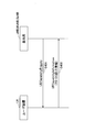
- FIG. 2 is a diagram for explaining the operation of the user apparatus UE at the time of switching of UL CC (hereinafter, CC means UL CC unless otherwise specified) in CA (or synchronous DC) in eNB.
- CC means UL CC unless otherwise specified
- CA synchronous DC
- the user apparatus UE performs UL transmission related to CA using CC # 1 and CC # 2.
- the setting is made to switch from CC # 1 to CC # 2 at the timing of the subframe shown in A.
- switching between CCs takes a certain amount of time, and in this example (the following example is also the same), the period is set to one subframe. However, one subframe is only an example. This period is called a transition period.
- the user apparatus UE performs UL transmission by CC # 1 before the subframe of A, and switches the UL transmission to CC # 2 through the transition period. Since CC # 1 and CC # 2 are synchronized, the time boundary between the subframe indicated by A in CC # 1 and the corresponding subframe in CC # 2 matches, so that switching can be performed smoothly. it can.
- FIG. 3 shows an example of asynchronous DC.
- CC # 1 is a CC of a cell in the MCG
- CC # 2 is a CC of a cell (a cell having a UL) in the SCG.
- the subframe in the transition period indicated by A is, for example, subframe # 0.
- the user apparatus UE performs UL transmission in CC # 1 until the transition period indicated by A in CC # 1, and uplink transmission in CC # 2 from the subframe next to subframe # 0 that is the transition period Switch to perform.
- the subframe of CC # 1 indicated by B is a subframe corresponding to the transition period in CC # 2. It overlaps with # 0. Therefore, in the subframe, the user apparatus UE may not be able to normally execute UL transmission on CC # 1. Further, since the subframe of CC # 2 indicated by C overlaps with subframe # 0 corresponding to the transition period in CC # 1, in this subframe, the user apparatus UE normally performs UL transmission on CC # 2. It may not be possible to execute.
- the present invention has been made in view of the above points, and in a mobile communication system that supports carrier aggregation, even when a plurality of cells constituting the carrier aggregation are asynchronous, uplink transmission by time switching between carriers is performed. It is an object of the present invention to provide a technique that allows a user apparatus to appropriately execute.
- a user apparatus that communicates with one or a plurality of base stations in a mobile communication system that supports carrier aggregation
- a user device including a transmitting unit.
- an uplink transmission switching method executed by a user apparatus that communicates with one or a plurality of base stations in a mobile communication system that supports carrier aggregation, Selecting a specific cell or a specific cell group as a reference for carrier switching timing of uplink transmission from a plurality of cells or a plurality of cell groups constituting the carrier aggregation; Switching from uplink transmission using the carrier of the first cell to uplink transmission using the carrier of the second cell based on the timing of the transition period in the selected specific cell or specific cell group
- An uplink transmission switching method comprising the steps of:
- the user apparatus in a mobile communication system that supports carrier aggregation, even when a plurality of cells constituting carrier aggregation are asynchronous, the user apparatus appropriately performs uplink transmission by time switching between carriers. It becomes possible to execute.
- FIG. It is a figure for demonstrating the operation example at the time of the switch from 5G to LTE in the modification 2.
- FIG. It is a figure which shows the example of a procedure in the modification 3.
- CG cell group
- MCG and SCG in DC are examples of CG
- CG is a concept that is not limited to MCG and SCG
- a group of a plurality of cells from some point of view is called CG.
- the CG includes a case of one cell.
- CA carrier aggregation
- CA carrier aggregation
- the “cell” constituting the CA is a cell in which the user apparatus UE is located, and may be referred to as a serving cell. Further, as an example, the “cell” constituting the CA consists of only a downlink CC, or a downlink CC and an uplink CC.
- the release of the “LTE” 3GPP standard in this specification and the claims is assumed to be a release in which CA is introduced, but is not limited thereto.
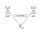
- FIG. 4 shows a configuration example of the mobile communication system according to the embodiment of the present invention.
- the mobile communication system according to the present embodiment includes a base station MeNB and a base station SeNB that are each connected to the core network 10, and enables dual connectivity (DC) with the user apparatus UE. It is said. Further, the base station MeNB and the base station SeNB can communicate with each other through, for example, an X2 interface.
- the DC is an asynchronous DC unless otherwise specified.
- the control described in the present embodiment may be applied to a synchronous DC or to a CA that is not a DC. You may apply.
- the user apparatus is basically described as UE, and the base station MeNB and the base station SeNB are described as MeNB and SeNB, respectively. Moreover, when not distinguishing a single base station and MeNB / SeNB in particular, the said base station is described as eNB.
- the MeNB when the MeNB determines to set DC for the UE based on a measurement report from the UE, the MeNB transmits an SeNB addition request (SeNB Addition Request) to the SeNB (step 101).
- the SeNB addition request includes MCG setting information and the like.
- the SeNB returns an SeNB addition request confirmation (SeNB Addition Request Acknowledgment) to the MeNB (step 102).
- the SeNB addition request confirmation includes SCG radio resource setting information and the like.
- the MeNB transmits an SeNB addition instruction (RRC Connection Reconfiguration) to the UE (Step 103).
- the SeNB addition instruction includes SCG radio resource setting information and the like.
- the UE applies the setting information, adds the SCG, and returns a setting completion (RRC Connection Reconfiguration Complete) to the MeNB (step 104).
- the MeNB returns a setting completion (SeNB Reconfiguration Complete) indicating that the setting (Reconfiguration) at the UE is successful to the SeNB (Step 105).
- UE establishes a synchronization with SCG by performing a random access procedure with respect to SCG (PSCell).
- DC between the UE and the MeNB / SeNB is set by the procedure as described above, and DC communication becomes possible.
- the UE performs UL communication in DC using a plurality of CCs (example: 2CC).
- the plurality of CCs are included in asynchronous CGs (eg, MCG and SCG, and plural SCGs).
- UE performs UL transmission always using one CC in a time direction by switching the said several CC via a transition period (transient period).
- the UE uses the timing of the transition period in a cell included in a specific CG as a reference between CCs. Switching will be performed.
- the above-mentioned “cell included in a specific CG” is specified as one cell (eg, PCell), and therefore is used as a reference for the timing of the transition period. Is described as a specific cell / CG (meaning a specific cell or a specific CG).
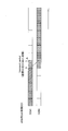
- FIG. 6 an operation example of UE UL transmission when the UE performs UL transmission with 2 CCs (CC # 1 and CC # 2) will be described. Note that FIG. 6 may be considered to indicate switching between 2 CCs when the UE performs UL transmission with 3 CCs or more.
- CC # 1 is, for example, a CC of a cell having a UL in MCG (eg, PCell).
- CC # 2 is, for example, a CC of a cell having a UL in SCG (eg, PSCell).
- each of the UE, MeNB, and SeNB is set to perform switching between CCs using the subframe # 0 as a transition period, and is configured to indicate that the transition period is one subframe. ing.
- This setting content is determined by the MeNB, for example, and is notified and set to the SeNB and the UE in steps 101 and 103 shown in FIG.
- the fact that the timing of CC # 1 becomes the reference for switching may be set from the MeNB (or SeNB) to the UE, or may be recognized by each device according to a predetermined rule described later.
- the UE performs UL transmission on CC # 1 up to the subframe indicated by A of CC # 1. That is, UL transmission allocation (scheduling) is performed from the eNB (example: MeNB) to the UE up to the subframe indicated by A of CC # 1.
- eNB example: MeNB
- subframe # 0 indicated by B in CC # 1 is a transition period
- scheduling from the eNB in CC # 1 is not performed.
- UE performs control which switches UL transmission from CC # 1 to CC # 2.
- the control for switching from CC # 1 to CC # 2 is, for example, switching the frequency of the transmitter from CC # 1 to CC # 2.
- subframe # 0 indicated by C is recognized as a transition period, and UE UL transmission is assigned from the subframe indicated by D.
- the UE sets the transition period to the period of the subframe indicated by B of CC # 1. Therefore, the UE detects that the period of the subframe indicated by D in CC # 2 overlaps with the transition period, and does not perform UL transmission by CC # 2 in the period of the subframe indicated by D, and performs the next E
- the UL transmission is started from the subframe indicated by. Thereby, for example, it can be avoided that abnormal UL transmission is performed in the transition period.
- CC # 2 has a higher priority than CC # 1
- CC # 2 is used as a reference
- the subframe indicated by A in CC # 1 is CC # 2. Since it overlaps with the transition period, UL transmission in the subframe is stopped.
- priority is determined for the cell / CG, and switching between CCs is performed based on the timing of the higher priority cell / CG.
- UL transmission is assigned to a UE from an eNB of a certain cell, and thereby, UL transmission is triggered in a certain subframe of the cell in the UE (step 201).
- the UE is a subframe in which the subframe overlaps at least partly with the transition period in another cell (cell of the other CC) having a higher priority than the cell (the cell of the CC triggered to transmit UL). Whether or not (step 202).
- Partially overlaps in step 202 means, for example, that they overlap for a certain threshold time or more.
- “another cell having a higher priority than the cell” includes a case where another cell belongs to a CG having a higher priority than the CG to which the cell belongs.
- step 203 the UE does not perform a triggered UL transmission (step 203). This case corresponds to a case where the subframe that has received the UL transmission trigger is a subframe indicated by C or D of CC # 2 shown in FIG. Moreover, when determination in step 202 of FIG. 7 is No, UE implements UL transmission (step 204).
- the specific cell / CG may be selected autonomously by the UE or based on an instruction from the eNB.
- the UE selects an MCG that is a CG including a PCell among 2CGs (MCG and SCG) to which 2CCs that perform UL transmission belong.
- MCG and SCG 2CGs
- a specific CG is selected, and the cell belonging to the MCG (the cell of one of the two CCs) is used as a timing reference.
- the cell belonging to the MCG may be a PCell or a cell other than the PCell in the MCG (a cell having a UL CC).
- the UE may select the PCell as a specific cell. In this case, it is the same as selecting MCG as a specific CG.
- CG including a PCell
- connectivity can be ensured.
- the UE selects an SCG that is a CG including a PSCell as a specific CG among 2CGs (MCG and SCG) to which the 2CC performing UL transmission belongs, and belongs to the SCG.
- the cell (one CC of 2 CCs) may be used as a timing reference.
- the cell belonging to the SCG may be a PSCell or a cell other than the PSCell in the SCG (a cell having a UL CC).
- the UE may select the PSCell as a specific cell. In this case, it is the same as selecting SCG as a specific CG.
- CG including PSCell as a specific CG as a reference for switching timing between CCs
- UP user plane
- the UE may determine a specific cell / CG based on the size of the cell index / CG index. For example, when the indexes of 2CG to which 2CC performing UL transmission belong are 1 and 2, the UE selects a CG having a smaller index (or a larger index) as a specific CG. Also, for example, when the indexes of 2 cells to which 2CCs that perform UL transmission belong are 1 and 5, the UE selects a cell with a smaller (or larger) index as a specific cell. Examples of the cell / CG index include CellIndex, SCellIndex, and CGIndex.
- a smaller cell (or larger one) as a specific cell / CG may be a predetermined matter in the UE and eNB (MeNB, SeNB), or the smaller index (or the eNB side) (or The larger one) may be determined, and the content of the determination may be notified to the UE.
- the UE may select a cell / CG in which a specific bearer or a specific LCH (logical channel) is set as the specific cell / CG. For example, the UE assigns a cell / CG in which a higher bearer (or LCH) with a higher QoS (example of communication path priority) out of two cells (2CG) to which the 2CC belongs to a specific cell / CG Select as CG.
- a higher bearer or LCH
- QoS example of communication path priority
- the UE may select a specific cell / CG based on the channel type (signal type) of UL transmission in multiple cells / CG performing UL transmission. For example, a cell / CG that transmits PUCCH among a plurality of cells / CG may be selected as a specific cell / CG. Further, for example, a cell / CG that transmits PRACH among a plurality of cells / CG may be selected as a specific cell / CG. Further, for example, a cell / CG that transmits a specific signal (eg, SR, ACK / NACK) among a plurality of cells / CG may be selected as the specific cell / CG. In addition, for example, existing Power scaling or dropping rules may be used.
- a specific signal eg, SR, ACK / NACK
- UE may select a specific cell / CG based on an instruction from the base station eNB.
- a specific cell / CG may be selected by the same method as the selection on the UE side described above, or the cell / CG may be selected by another policy. It is good also as performing.
- a specific cell / CG (cell or CG) to be used as a reference for the timing of the inter-CC transition period is designated from an eNB (eg, MeNB or SeNB).
- eNB eg, MeNB or SeNB
- the designation is made by, for example, a cell index / CG index or the like.
- the designation in step 301 may be performed simultaneously with the SeNB addition instruction in step 103 shown in FIG. 5 using the RRC signal.
- the designation in step 301 may be dynamically performed using a MAC signal or a PHY signal (PDCCH or the like).
- the eNB to UE may designate which subframe is used for switching (which subframe is used as the transition period) and the length of the transition period (number of subframes).
- step 302 the UE performs CC switching based on the cell / CG timing according to the designation in step 301 in UL transmission.
- the UE has received a UL transmission trigger in a certain CC among the two CCs that perform UL transmission, but cannot perform UL transmission in the CC due to a transition period of the other CC.
- the physical layer for example, radio unit
- the upper layer for example, the control unit that performs control of MAC or RRC
- UL transmission can be performed by the determination of the upper layer.
- the eNB may be notified of the absence.
- the notification includes, for example, the index of the cell that could not be transmitted by UL, the subframe number that could not be transmitted by UL, and the like. By performing such notification, the eNB side performs UL transmission allocation, but it is possible to grasp that UL transmission has not been performed in the UE, and for example, the event can be utilized for subsequent scheduling.
- the notification in step 303 may be performed regardless of whether the UE autonomously selects a specific cell / CG or performs an instruction from the eNB.
- the instruction content in step 301 may be a specific cell / CG designation or an instruction on a specific cell / CG selection method (the selection method already described).
- this 2 CC is not limited to the case where the UE has the capability of 2 UL CC, and the UE has the capability of CA of 3 UL CC or higher and the CA of 3 UL CC or higher. May be set, any 2CC among the 3 CCs or more may be used.
- FIG. 4 shows a case where there is one SeNB (SCG), this is an example, and the number of SCGs may be two or more. That is, the number of CGs constituting the DC may be 3 or more. Even in this case, a specific cell / CG may be selected between any two CGs (corresponding to between two CCs to be switched) as described above.
- SCG SeNB
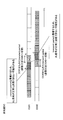
- the priority of the cell / CG may be determined in advance, and the priority may be preset between the UE, MeNB, and SeNB. Further, for example, the MeNB may determine the priority of the cell / CG and notify the UE and each SeNB of the priority.
- the priority of the CG to which CC # 1 of 3CC (CC # 1, CC # 2, CC # 3) used by the UE for UL transmission belongs is high (out of 3CG)
- the priority of the CG to which CC # 2 belongs is determined to be medium
- the priority of the CG to which CC # 3 belongs is determined to be low.
- the order of the priorities is CC # 1> CC # 2> CC # 3.
- the UE performs UL transmission in CC # 1, and switches from CC # 1 to CC # 2 in the transition period of the subframe indicated by A. Since the timing of CC # 1 is a reference between CC # 1 and CC # 2, UL transmission is not performed in the subframe indicated by B in CC # 2 (which overlaps with the reference transition period), and is indicated by C Execute UL transmission from the subframe. Next, the UE performs switching from CC # 2 to CC # 3 in the transition period of the subframe indicated by D. Since CC # 2 timing is a reference between CC # 2 and CC # 3, UL transmission is not performed in the subframe indicated by E in CC # 3 (overlapping with the reference transition period), and is indicated by F Execute UL transmission from the subframe.
- Radio frame In the existing LTE, the structure of a radio frame is defined such that one radio frame is 10 ms, one subframe is 1 ms, and one slot is 0.5 ms (Non-patent Document 2).
- One subframe corresponds to TTI (Transmission Time Interval) which is a minimum unit of scheduling. That is, for each subframe, a resource block (RB) is allocated to the UE selected by eNB scheduling.
- RB is composed of, for example, 12 subcarriers (OFDM subcarriers) in the frequency direction and 7 symbols (OFDM symbols) in the time direction.
- 5G 5th generation wireless technology
- 3GPP 3rd Generation Partnership Project
- 5G in order to reduce the delay of wireless communication, it is considered to shorten 1 TTI (eg, shorten to 0.1 ms).
- an LTE cell (PCell) as a macro cell is formed by a base station eNB, for example, a 5G cell (SCell) as a small cell is formed by an RRE (remote radio device) extending from the eNB, and the UE High-throughput communication is executed by CA using the LTE cell and the 5G cell.
- the configuration shown in FIG. 12 may be a DC configuration.
- the MeNB forms an LTE macro cell (MCG)
- the SeNB forms a 5G small cell (SCG).
- the configuration of the mobile communication system according to the second modification may be the DC (asynchronous or synchronous) configuration shown in FIG. 4 or the CA configuration shown in FIG.
- the transition period between LTE CCs is one subframe in LTE (the LTE TTI length is referred to as LTE subframe), and the transition period between 5G CCs is 1 in 5G If it is a subframe (5G TTI length, referred to as a 5G subframe) and CC switching between the same RAT, switching between CCs is performed by applying the transition period in the RAT. Good. However, it is not clear which transition period should be applied in switching between LTE CC and 5G CC.
- the transition period in the transition between CCs between different RATs of UL CA is determined according to the direction of transition.
- a transition between LTE and 5G will be described as an example of different RATs.
- the RAT is not limited to these, and other RATs constituting CA (including DC) can be used. It is.
- FIG. 13 and FIG. 13 show an example of UE operation when switching between LTE CC and 5G CC when the UE performs UL transmission in multiple CCs including LTE CC and 5G CC.
- the UE may perform UL transmission in multiple CCs including an LTE CC and a 5G CC, and the UE may perform CA under the same eNB that is not a DC using the LTE CC and the 5G CC.
- DC may be performed using a CG to which an LTE CC belongs (eg, MCG) and a CG to which a 5G CC belongs (eg, SCG). Further, the DC may be asynchronous or synchronous. Further, in this example, it is assumed that switching is performed in the UE and eNB (MeNB, SeNB) to perform switching in subframe # 0 of LTE (RAT having a longer TTI length).
- MCG CG to which an LTE CC belongs
- SCG a CG to which a 5G CC belongs
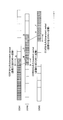
- FIG. 13 shows an example in which the UE switches from LTE CC # 1 to 5G CC # 2.
- the UE performs switching from CC # 1 to CC # 2 (5G) using subframe # 0 indicated by A in CC # 1 (LTE) as a transition period. That is, the UE performs UL transmission in CC # 1 up to the LTE subframe indicated by B, and uses one LTE subframe (period indicated by A) as a transition period, and during this period, both CC # 1 and CC # 2 perform UL transmission. Without starting the transmission, the UL transmission in CC # 2 is started from the 5G subframe indicated by C.
- the transition period from LTE to 5G is set to one LTE subframe, this is set in advance on the UE and eNB side. Alternatively, it may be set from the eNB side to the UE with an RRC signal or the like.
- transition period from LTE to 5G is set as one LTE subframe, which is merely an example, and may be longer or shorter depending on the UE capability.
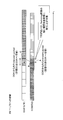
- FIG. 14 shows an example in which the UE switches from 5G CC # 2 to LTE CC # 1.
- the UE switches from CC # 2 to CC # 1 (LTE) using the 4 ⁇ 5G subframe indicated by A in CC # 2 (5G) as a transition period.
- the UE performs UL transmission in CC # 2 up to the 5G subframe indicated by B, and uses the 4 ⁇ 5G subframe (period indicated by A) as the transition period, and the period is both CC # 1 and CC # 2.
- UL transmission in CC # 1 is started from the LTE subframe indicated by C without performing UL transmission.
- the UE detects that it is the timing of transition at the start of LTE subframe # 0, but since the transition from 5G to LTE can be performed in the period of 4 ⁇ 5G subframe, B 5G UL transmission is performed up to the 5G subframe shown in FIG.
- the transition period from 5G to LTE is a period of 4 ⁇ 5G subframes, but this is only an example, and may be longer or shorter depending on the UE capability. Also good.
- UE determines each of the transition period from CC of a LTE cell to CC of 5G cell, and the transition period from CC of 5G cell to CC of LTE cell, and can apply at the time of corresponding switching. These transition periods may be set (held) in advance on the UE and eNB side, or may be set from the eNB side to the UE with an RRC signal or the like.
- the transition timing between CCs is based on the LTE side, but may be based on the 5G side. Which is the reference may be selected according to the selection method of the specific cell / CG described so far.
- LTE can be used as a reference for transition timing between CCs.
- the RAT cell / CG having the longer (or shorter) TTI length may be used as a reference for transition timing as a specific cell / CG.
- the UE may notify the eNB (MeNB in this example) as capability information whether or not the UE supports the inter-CC transition function in UL transmission in DC.
- the inter-CC transition function is referred to as TS-DC (Time switched DC).
- the MeNB that has received the TS-DC capability information can determine, for example, whether to set the UL CA in a plurality of asynchronous cells in the UE based on the capability information.
- the base station is a MeNB, but it may be an eNB that does not constitute a DC or a SeNB.
- Step 401 the UE receives a UE capability inquiry (UE Capability Enquiry) from the MeNB.
- Step 402 the UE transmits UE capability information (UE Capability Information) to the MeNB.
- the UE notifies the MeNB of information indicating whether or not the UE supports TS-DC as UE capability information (including transmission as information included in the UE capability information). That is, notification is made in units of UE.
- the UE that has notified that the TS-DC is capable supports TS-DC regardless of whether it is synchronous or asynchronous for any band combination that supports UL DC.
- the UE may notify the UE capability information of information indicating whether TS-DC is possible for each synchronous DC and asynchronous DC. That is, for example, information indicating that TS-DC is possible with synchronous DC but TS-DS cannot be performed with asynchronous DC (the function described in this embodiment is not provided) is notified.
- the UE that notifies the information with the capability of synchronous TS-DC supports TS-DC for the band combination that supports synchronous DC. Further, the UE that notifies the information indicating the capability of asynchronous TS-DC supports TS-DC for a band combination that supports asynchronous DC.
- the UE may notify each band combination whether TS-DC is possible.
- the UE that notifies this capability information supports TS-DC for the corresponding band combination.
- capability information indicating whether TS-DC is possible at the subset level of the band combination may be notified.
- the UE may notify the TS-DC capability information notification together with how much a transition period is necessary. How much the transition period is necessary can be notified by, for example, the time required for the transition period (eg, ⁇ s), the number of TTIs (number of subframes) in LTE or 5G, and the like.
- the user apparatus UE may be provided with the function which can perform all the processing content which concerns on said description, and it is good also as having a one part function. .
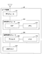
- FIG. 16 shows a functional configuration diagram of the UE according to the present embodiment.
- the UE includes a UL signal transmission unit 101, a DL signal reception unit 102, an RRC management unit 103, and a UL transmission switching control unit 104.
- FIG. 16 shows only functional units that are particularly related to the embodiment of the present invention in the UE, and also has a function (not shown) for performing an operation based on LTE.
- the functional configuration shown in FIG. 16 is merely an example. As long as the operation according to the present embodiment can be performed, the function classification and the name of the function unit may be anything.
- the UL signal transmission unit 101 includes a function of generating various types of physical layer signals from a higher layer signal to be transmitted from the UE and wirelessly transmitting the signals.
- the DL signal receiving unit 102 includes a function of wirelessly receiving various signals from the eNB and acquiring higher layer signals from the received physical layer signals.
- Each of the UL signal transmission unit 101 and the DL signal reception unit 102 includes a function of executing CA (including DC) that performs communication by bundling a plurality of CCs. However, for UL transmission performed by the UL signal transmission unit 101, CA communication is performed by switching between CCs according to time.
- each of the UL signal transmitting unit 101 and the DL signal receiving unit 102 includes a packet buffer and performs layer 1 (PHY) and layer 2 (MAC, RLC, PDCP) processing.
- layer 1 PHY
- layer 2 MAC, RLC, PDCP
- the UL signal transmission unit 101 and the DL signal reception unit 102 can execute CA (including DC) between different RATs such as LTE and 5G.
- the RRC management unit 103 includes a function of performing processing such as setting / change / management of CA (DC) information, configuration change, and the like while performing transmission and reception of RRC messages with the eNB.
- the RRC management unit 103 includes information on capability (capability) of the user apparatus UE and notifies the base station eNB of capability information as described in the third modification.
- the UL transmission switching control unit 104 performs switching control between CCs of UL transmission according to the present embodiment (including each modification). For example, the UL transmission switching control unit 104 holds or determines setting information (transition period length, transition period arrival timing, transition reference cell) related to switching between CCs, and the information and the passage of time. Accordingly, it is possible to instruct the UL signal transmission unit 101 to switch between CCs. Further, the UL transmission switching control unit 104 can instruct the UL signal transmission unit 101 to stop / execute UL transmission by performing control according to the flow shown in FIG.
- setting information transition period length, transition period arrival timing, transition reference cell
- the UL transmission switching control unit 104 includes a function of selecting a specific cell or a specific cell group as a reference for uplink transmission carrier switching timing from a plurality of cells or a plurality of cell groups constituting the CA.
- the UL transmission switching control unit 104 performs the first transition period, which is a switching period from the LTE cell carrier to the 5G cell carrier, and the LTE from the 5G cell carrier.
- Each cell may have a function of holding or determining each of the second transition period, which is a switching period of the cell to the carrier.
- the UL transmission switching control unit 104 may be included in the UL signal transmission unit 101.
- the configuration of the user apparatus UE shown in FIG. 16 may be entirely realized by a hardware circuit (for example, one or a plurality of IC chips), or a part may be configured by a hardware circuit, and the other part may be a CPU. And a program.
- a hardware circuit for example, one or a plurality of IC chips
- a part may be configured by a hardware circuit, and the other part may be a CPU.
- a program for example, one or a plurality of IC chips
- FIG. 17 is a diagram illustrating an example of a hardware (HW) configuration of the user apparatus UE.
- FIG. 17 shows a configuration closer to the mounting example than FIG.
- the UE controls an apparatus that performs processing such as an RE (Radio Equipment) module 151 that performs processing related to a radio signal, a BB (Base Band) processing module 152 that performs baseband signal processing, and a higher layer. It has a module 153 and a USIM slot 154 which is an interface for accessing a USIM card.
- RE Radio Equipment
- BB Base Band
- the RE module 151 should transmit from the antenna by performing D / A (Digital-to-Analog) conversion, modulation, frequency conversion, power amplification, etc. on the digital baseband signal received from the BB processing module 152 Generate a radio signal.
- a digital baseband signal is generated by performing frequency conversion, A / D (Analog to Digital) conversion, demodulation, and the like on the received wireless signal, and the digital baseband signal is passed to the BB processing module 152.
- the RE module 151 includes functions such as a physical layer in the UL signal transmission unit 101 and the DL signal reception unit 102 in FIG.
- the BB processing module 152 performs processing for mutually converting an IP packet and a digital baseband signal.
- a DSP (Digital Signal Processor) 162 is a processor that performs signal processing in the BB processing module 152.
- the memory 172 is used as a work area for the DSP 162.
- the BB processing module 152 includes, for example, functions such as layer 2 in the UL signal transmission unit 101 and the DL signal reception unit 102 in FIG. 16, an RRC management unit 103, and a UL transmission switching control unit 104. Note that all or part of the RRC management unit 103 and the UL transmission switching control unit 104 may be included in the device control module 153.
- the device control module 153 performs IP layer protocol processing, various application processing, and the like.
- the processor 163 is a processor that performs processing performed by the device control module 153.
- the memory 173 is used as a work area for the processor 163.
- the processor 163 reads and writes data with the USIM through the USIM slot 154.
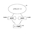
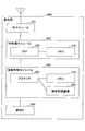
- FIG. 18 shows a functional configuration diagram of the eNB according to the present embodiment.
- the eNB includes a DL signal transmission unit 201, a UL signal reception unit 202, an RRC management unit 203, and a scheduling unit 204.
- FIG. 18 shows only functional units that are particularly related to the embodiment of the present invention in the eNB, and also has a function (not shown) for performing an operation based on at least LTE. Further, the functional configuration shown in FIG. 18 is merely an example. As long as the operation according to the present embodiment can be performed, the function classification and the name of the function unit may be anything.
- the eNB may be a single eNB, or may be either a MeNB or a SeNB when performing DC by setting (Configuration).
- the DL signal transmission unit 201 includes a function of generating various physical layer signals from a higher layer signal to be transmitted from the eNB and wirelessly transmitting the signals.
- the UL signal receiving unit 202 includes a function of wirelessly receiving various signals from each UE and acquiring a higher layer signal from the received physical layer signal.
- Each of the DL signal transmission unit 201 and the UL signal reception unit 202 includes a function of executing CA (including DC) that performs communication by bundling a plurality of CCs.
- CA including DC
- the DL signal transmission unit 201 and the UL signal reception unit 202 may include a radio communication unit installed remotely from the main body (control unit) of the eNB, such as an RRE.
- Each of the DL signal transmission unit 201 and the UL signal reception unit 202 includes a packet buffer, and is assumed to perform layer 1 (PHY) and layer 2 (MAC, RLC, PDCP) processing (however, this is not the only case). Not.) Further, the DL signal transmission unit 201 and the UL signal reception unit 202 can also execute CA (including DC) between different RATs such as LTE and 5G.
- layer 1 PHY
- layer 2 MAC, RLC, PDCP
- CA including DC
- the RRC management unit 203 includes a function of performing processing such as setting / change / management of CA (DC), configuration change and the like while performing transmission / reception of RRC messages with the UE. Since the RRC management unit 203 is a functional unit that sets CA (DC), it may be called a setting unit. Further, the RRC management unit 203 may include a function of determining a specific cell / CG for the UE and notifying the UE via the DL signal transmission unit 201.
- the scheduling unit 204 performs scheduling for each cell for the user apparatus UE that performs CA (including DC), creates PDCCH allocation information, and transmits the PDCCH including the allocation information to the DL signal transmission unit 201.
- CA including DC
- the function to instruct is included.
- the configuration of the base station eNB shown in FIG. 18 may be entirely realized by a hardware circuit (eg, one or a plurality of IC chips), a part is constituted by a hardware circuit, and the other part is a CPU. And a program.
- a hardware circuit eg, one or a plurality of IC chips
- a part is constituted by a hardware circuit
- the other part is a CPU.
- a program e.g, one or a plurality of IC chips
- FIG. 19 is a diagram illustrating an example of a hardware (HW) configuration of the base station eNB.
- HW hardware
- FIG. 19 shows a configuration closer to the mounting example than FIG.
- the base station eNB includes an RE module 251 that performs processing related to a radio signal, a BB processing module 252 that performs baseband signal processing, a device control module 253 that performs processing such as an upper layer, a network, And a communication IF 254 which is an interface for connection.
- the RE module 251 generates a radio signal to be transmitted from the antenna by performing D / A conversion, modulation, frequency conversion, power amplification, and the like on the digital baseband signal received from the BB processing module 252.
- a digital baseband signal is generated by performing frequency conversion, A / D conversion, demodulation, and the like on the received radio signal, and passed to the BB processing module 252.
- the RE module 251 includes functions such as a physical layer in the DL signal transmission unit 201 and the UL signal reception unit 202 in FIG.
- the BB processing module 252 performs processing for mutually converting an IP packet and a digital baseband signal.
- the DSP 262 is a processor that performs signal processing in the BB processing module 252.
- the memory 272 is used as a work area for the DSP 252.
- the BB processing module 252 includes, for example, functions such as layer 2 in the DL signal transmission unit 201 and the UL signal reception unit 202 in FIG. 18, an RRC management unit 203, and a scheduling unit 204. Note that all or part of the functions of the RRC management unit 203 and the scheduling unit 204 may be included in the device control module 253.
- the device control module 253 performs IP layer protocol processing, OAM processing, and the like.
- the processor 263 is a processor that performs processing performed by the device control module 253.
- the memory 273 is used as a work area for the processor 263.
- the auxiliary storage device 283 is an HDD, for example, and stores various setting information for the base station eNB itself to operate.
- a user apparatus that communicates with one or a plurality of base stations in a mobile communication system that supports carrier aggregation, and a plurality of cells or a plurality of cells constituting the carrier aggregation.
- a control unit that selects a specific cell or a specific cell group as a reference for the carrier switching timing of uplink transmission from the cell group of the selected cell group, and a transition period timing in the selected specific cell or the specific cell group.
- a user apparatus including a transmission unit that performs switching from uplink transmission using a carrier of a first cell to uplink transmission using a carrier of a second cell.
- the UL transmission switching control unit 104 described above corresponds to the control unit described above.
- the transmitting unit when the first cell is a cell included in the selected specific cell or the specific cell group, uplinks in a subframe overlapping with the transition period in the second cell. You may comprise so that transmission may not be performed. With this configuration, it is possible to avoid performing abnormal uplink transmission, which can contribute to power consumption reduction and interference avoidance.
- the control unit may select PCell or a cell group including PCell as the specific cell or the specific cell group. With this configuration, connectivity can be ensured.
- the control unit may select the specific cell or the specific cell group based on an index of each cell or each cell group in the plurality of cells or the plurality of cell groups. With this configuration, a specific cell or a specific cell group can be selected with simple determination logic.
- the control unit may select the specific cell or the specific cell group based on the priority of the communication path set in each cell or each cell group in the plurality of cells or the plurality of cell groups. Good. With this configuration, for example, important communication can be protected.
- the control unit selects the specific cell or the specific cell group based on a type of channel or a type of signal transmitted in each cell or each cell group in the plurality of cells or the plurality of cell groups. It is good as well. With this configuration, for example, communication related to a specific channel or signal can be protected.
- the control unit includes the A first transition period that is a switching period from the carrier of the first cell to the carrier of the second cell, and a second transition that is a switching period from the carrier of the second cell to the carrier of the first cell.
- the transmission unit uses the first transition period when switching from the carrier of the first cell to the carrier of the second cell, and the carrier from the second cell
- the second transition period may be used when switching to the carrier of the first cell.
- uplink transmission time switching can be appropriately performed in CA between different RATs such as LTE-5G CA.
- the control unit may select the specific cell or the specific cell group based on an instruction from the base station. This configuration enables flexible control according to the policy on the network side.
- the transmitting unit may notify the base station of capability information regarding switching of uplink transmission between carriers.
- the capability of the user apparatus regarding switching of uplink transmission between carriers can be grasped, and appropriate settings can be made when setting CA (DC) to the user apparatus.
- the user apparatus UE described in the present embodiment may include a CPU and a memory, and may be realized by a program being executed by a CPU (processor).
- the first and second embodiments may be used.
- the configuration may be realized by hardware such as a hardware circuit provided with the processing logic described in the above, or a program and hardware may be mixed.
- the base station eNB described in the present embodiment may include a CPU and a memory, and may be realized by a program being executed by a CPU (processor).
- the first and second embodiments The configuration may be realized by hardware such as a hardware circuit provided with the processing logic described in the above, or a program and hardware may be mixed.
- the operations of a plurality of functional units may be physically performed by one component, or the operations of one functional unit may be physically performed by a plurality of components.
- the user apparatus and the base station have been described using functional block diagrams, but such an apparatus may be realized in hardware, software, or a combination thereof.
- Software operated by a processor included in a user apparatus and software operated by a processor included in a base station according to the embodiment of the present invention are random access memory (RAM), flash memory, read-only memory (ROM), EPROM, and EEPROM. , A register, a hard disk (HDD), a removable disk, a CD-ROM, a database, a server, or any other suitable storage medium.
- UE user apparatus eNB, MeNB, SeNB Base station 101 UL signal transmission unit 102 DL signal reception unit 103 RRC management unit 104 UL transmission switching control unit 151 RE module 152 BB processing module 153 device control module 154 USIM slot 201 DL signal transmission unit 202 UL signal receiving unit 203 RRC management unit 204 Scheduling unit 251 RE module 252 BB processing module 253 Device control module 254 Communication IF
Landscapes
- Engineering & Computer Science (AREA)
- Signal Processing (AREA)
- Computer Networks & Wireless Communication (AREA)
- Mobile Radio Communication Systems (AREA)
Abstract
Priority Applications (3)
| Application Number | Priority Date | Filing Date | Title |
|---|---|---|---|
| CN201680003307.4A CN107079443A (zh) | 2015-02-20 | 2016-02-17 | 用户装置以及上行发送切换方法 |
| JP2017500713A JPWO2016133123A1 (ja) | 2015-02-20 | 2016-02-17 | ユーザ装置、及び上り送信切り替え方法 |
| US15/513,008 US20170303182A1 (en) | 2015-02-20 | 2016-02-17 | User apparatus, and uplink transmission switching method |
Applications Claiming Priority (2)
| Application Number | Priority Date | Filing Date | Title |
|---|---|---|---|
| JP2015032343 | 2015-02-20 | ||
| JP2015-032343 | 2015-02-20 |
Publications (1)
| Publication Number | Publication Date |
|---|---|
| WO2016133123A1 true WO2016133123A1 (fr) | 2016-08-25 |
Family
ID=56692317
Family Applications (1)
| Application Number | Title | Priority Date | Filing Date |
|---|---|---|---|
| PCT/JP2016/054581 WO2016133123A1 (fr) | 2015-02-20 | 2016-02-17 | Équipement d'utilisateur et procédé de commutation de transmission en liaison montante |
Country Status (4)
| Country | Link |
|---|---|
| US (1) | US20170303182A1 (fr) |
| JP (1) | JPWO2016133123A1 (fr) |
| CN (1) | CN107079443A (fr) |
| WO (1) | WO2016133123A1 (fr) |
Cited By (12)
| Publication number | Priority date | Publication date | Assignee | Title |
|---|---|---|---|---|
| WO2018083374A1 (fr) * | 2016-11-04 | 2018-05-11 | Nokia Technologies Oy | Coordination de configuration inter-rat |
| WO2018144193A1 (fr) * | 2017-02-01 | 2018-08-09 | Qualcomm Incorporated | Techniques de gestion de connectivité double dans une liaison montante |
| WO2018143856A1 (fr) * | 2017-02-06 | 2018-08-09 | Telefonaktiebolaget Lm Ericsson (Publ) | Adaptation d'un paramètre temporel transitoire de marche/arrêt d'un ue pour différents modèles d'intervalle de temps d'émission |
| WO2018174802A1 (fr) * | 2017-03-24 | 2018-09-27 | Telefonaktiebolaget Lm Ericsson (Publ) | Optimisation de performances de démodulation de réseau par une signalisation du temps de transition d'un équipement d'utilisateur pris en charge |
| JP2019004469A (ja) * | 2017-06-15 | 2019-01-10 | アップル インコーポレイテッドApple Inc. | Rat間二重接続性ue用のtdm伝送 |
| WO2019029333A1 (fr) * | 2017-08-11 | 2019-02-14 | 华为技术有限公司 | Procédé et appareil de programmation de ressource |
| JP2020502881A (ja) * | 2016-11-09 | 2020-01-23 | テレフオンアクチーボラゲット エルエム エリクソン(パブル) | ユーザプレーン切替えのためのネットワークノードおよびネットワークノードにおける方法 |
| CN111492713A (zh) * | 2018-01-11 | 2020-08-04 | 华为技术有限公司 | 用于在带宽部分之间切换的方法及设备 |
| CN113490247A (zh) * | 2018-11-26 | 2021-10-08 | Oppo广东移动通信有限公司 | 一种数据处理方法、设备及存储介质 |
| CN114040457A (zh) * | 2017-01-05 | 2022-02-11 | 日本电气株式会社 | 无线接入网节点、无线终端及其方法和计算机可读介质 |
| US11553513B2 (en) | 2017-02-06 | 2023-01-10 | Telefonaktiebolaget Lm Ericsson (Publ) | Methods and apparatuses for determining a placement and duration of a transient period of an on/off time mask for uplink transmission |
| US11888621B2 (en) | 2017-09-05 | 2024-01-30 | Ofinno, Llc | Uplink channel switching capability and selecting between uplink channels in a cell group based thereon |
Families Citing this family (17)
| Publication number | Priority date | Publication date | Assignee | Title |
|---|---|---|---|---|
| US10966194B2 (en) * | 2015-04-15 | 2021-03-30 | Qualcomm Incorporated | Coordinated wireless communications using multiple transmission time intervals |
| ES2898834T3 (es) * | 2016-04-28 | 2022-03-09 | Sharp Kk | Dispositivo terminal, dispositivo de estación base y métodos de comunicación |
| US10602454B2 (en) * | 2016-05-10 | 2020-03-24 | Lg Electronics Inc. | Method for controlling uplink transmission power in wireless communication system and device therefor |
| JP6763229B2 (ja) | 2016-08-08 | 2020-09-30 | ソニー株式会社 | 通信装置、通信方法、及びプログラム |
| CN109792719B (zh) | 2016-09-29 | 2023-04-18 | 松下电器(美国)知识产权公司 | 通信方法、通信装置和通信系统 |
| EP3531762B1 (fr) * | 2016-10-28 | 2022-02-23 | Huawei Technologies Co., Ltd. | Procédé et dispositif de rétroaction de message pour une agrégation de porteuses |
| US11304164B2 (en) | 2016-11-18 | 2022-04-12 | Qualcomm Incorporated | Asynchronous CA handling |
| WO2018199641A1 (fr) * | 2017-04-27 | 2018-11-01 | 엘지전자 주식회사 | Procédé et dispositif de configuration et de rapport de mesure pour interfonctionnement lte/nr dans un système de communication sans fil |
| WO2019056311A1 (fr) * | 2017-09-22 | 2019-03-28 | 富士通株式会社 | Procédé et appareil de transmission en liaison montante autonome et système de communication |
| CN111630894B (zh) * | 2017-11-28 | 2023-10-10 | 瑞典爱立信有限公司 | 小区组之间的传输的切换 |
| EP3745771A4 (fr) * | 2018-01-25 | 2021-11-17 | NTT DoCoMo, Inc. | Équipement utilisateur et dispositif station de base |
| US11012913B2 (en) * | 2019-04-08 | 2021-05-18 | Qualcomm Incorporated | User equipment capability-based transition |
| WO2020222270A1 (fr) * | 2019-05-01 | 2020-11-05 | 株式会社Nttドコモ | Équipement d'utilisateur et procédé de communication |
| WO2021051253A1 (fr) * | 2019-09-17 | 2021-03-25 | Qualcomm Incorporated | Interruption de transmission de liaison montante destinée à une commutation de porteuse de liaison montante sur la base, au moins en partie, d'une priorité de canal |
| EP4052522A4 (fr) * | 2019-11-01 | 2023-06-28 | Qualcomm Incorporated | Commutation de porteuse de liaison montante pour dispositifs sans fil |
| WO2022016372A1 (fr) * | 2020-07-21 | 2022-01-27 | Qualcomm Incorporated | Procédés et appareil permettant de commuter des emplacements de période |
| US20230254848A1 (en) * | 2020-08-25 | 2023-08-10 | Qualcomm Incorporated | Peak data rate calculation for uplink transmit switching |
Citations (1)
| Publication number | Priority date | Publication date | Assignee | Title |
|---|---|---|---|---|
| JP2013102398A (ja) * | 2011-11-09 | 2013-05-23 | Ntt Docomo Inc | 無線通信システム、ユーザ端末及び無線通信方法 |
Family Cites Families (4)
| Publication number | Priority date | Publication date | Assignee | Title |
|---|---|---|---|---|
| CN102187727B (zh) * | 2009-03-12 | 2015-03-25 | Lg电子株式会社 | 无线通信系统中在用户设备处切换操作载波的方法 |
| CN102396280B (zh) * | 2009-04-09 | 2013-04-17 | 华为技术有限公司 | 一种随机接入方法、演进基站及终端设备 |
| CN102118801B (zh) * | 2011-03-31 | 2013-07-24 | 电信科学技术研究院 | 多载波聚合系统中的上行传输方法和设备 |
| US8995381B2 (en) * | 2012-04-16 | 2015-03-31 | Ofinno Technologies, Llc | Power control in a wireless device |
-
2016
- 2016-02-17 US US15/513,008 patent/US20170303182A1/en not_active Abandoned
- 2016-02-17 CN CN201680003307.4A patent/CN107079443A/zh active Pending
- 2016-02-17 JP JP2017500713A patent/JPWO2016133123A1/ja not_active Withdrawn
- 2016-02-17 WO PCT/JP2016/054581 patent/WO2016133123A1/fr active Application Filing
Patent Citations (1)
| Publication number | Priority date | Publication date | Assignee | Title |
|---|---|---|---|---|
| JP2013102398A (ja) * | 2011-11-09 | 2013-05-23 | Ntt Docomo Inc | 無線通信システム、ユーザ端末及び無線通信方法 |
Non-Patent Citations (3)
| Title |
|---|
| INTEL CORPORATION: "Dual connectivity for UEs supporting one UL CC[ online", 3GPP TSG-RAN WG2#81BIS R2-131410, 6 April 2013 (2013-04-06), Retrieved from the Internet <URL:http://www.3gpp.org/ftp/tsg_ran/WG2_RL2/TSGR2_81bis/Docs/R2-131410.zip> * |
| NTT DOCOMO, INC.: "Specification impacts of 1CC transmission in a TTI for UL CA", 3GPP TSG-RAN WG2#79 R2-123998, 7 August 2012 (2012-08-07), Retrieved from the Internet <URL:http://www.3gpp.org/ftp/tsg_ran/WG2_RL2/TSGR2_79/Docs/R2-123998.zip> * |
| PANASONIC ET AL.: "UE capability on SCE and issue on single Tx[ online", 3GPP TSG-RAN WG2#83 R2- 132432, 9 August 2013 (2013-08-09), Retrieved from the Internet <URL:http://www.3gpp.org/ftp/tsg_ran/WG2_RL2/TSGR2_83/Docs/R2-132432.zip> * |
Cited By (24)
| Publication number | Priority date | Publication date | Assignee | Title |
|---|---|---|---|---|
| WO2018083374A1 (fr) * | 2016-11-04 | 2018-05-11 | Nokia Technologies Oy | Coordination de configuration inter-rat |
| US11252575B2 (en) | 2016-11-04 | 2022-02-15 | Nokia Technologies Oy | Inter-RAT configuration coordination |
| US20190246286A1 (en) * | 2016-11-04 | 2019-08-08 | Nokia Technologies Oy | Inter-rat configuration coordination |
| JP2020502881A (ja) * | 2016-11-09 | 2020-01-23 | テレフオンアクチーボラゲット エルエム エリクソン(パブル) | ユーザプレーン切替えのためのネットワークノードおよびネットワークノードにおける方法 |
| CN114040457A (zh) * | 2017-01-05 | 2022-02-11 | 日本电气株式会社 | 无线接入网节点、无线终端及其方法和计算机可读介质 |
| WO2018144193A1 (fr) * | 2017-02-01 | 2018-08-09 | Qualcomm Incorporated | Techniques de gestion de connectivité double dans une liaison montante |
| CN110235511B (zh) * | 2017-02-01 | 2020-11-27 | 高通股份有限公司 | 用于管理上行链路中的双连接的技术 |
| US10159107B2 (en) | 2017-02-01 | 2018-12-18 | Qualcomm Incorporated | Techniques for managing dual connectivity in an uplink |
| CN110235511A (zh) * | 2017-02-01 | 2019-09-13 | 高通股份有限公司 | 用于管理上行链路中的双连接的技术 |
| US11553513B2 (en) | 2017-02-06 | 2023-01-10 | Telefonaktiebolaget Lm Ericsson (Publ) | Methods and apparatuses for determining a placement and duration of a transient period of an on/off time mask for uplink transmission |
| WO2018143856A1 (fr) * | 2017-02-06 | 2018-08-09 | Telefonaktiebolaget Lm Ericsson (Publ) | Adaptation d'un paramètre temporel transitoire de marche/arrêt d'un ue pour différents modèles d'intervalle de temps d'émission |
| WO2018174802A1 (fr) * | 2017-03-24 | 2018-09-27 | Telefonaktiebolaget Lm Ericsson (Publ) | Optimisation de performances de démodulation de réseau par une signalisation du temps de transition d'un équipement d'utilisateur pris en charge |
| US11115979B2 (en) | 2017-03-24 | 2021-09-07 | Telefonaktiebolaget LM Ericsson (Publ) Stockholm, Sweden | Optimizing network demodulation performances by signaling supported UE transient time |
| JP2019004469A (ja) * | 2017-06-15 | 2019-01-10 | アップル インコーポレイテッドApple Inc. | Rat間二重接続性ue用のtdm伝送 |
| US11006473B2 (en) | 2017-08-11 | 2021-05-11 | Huawei Technologies Co., Ltd. | Resource scheduling method and apparatus |
| WO2019029333A1 (fr) * | 2017-08-11 | 2019-02-14 | 华为技术有限公司 | Procédé et appareil de programmation de ressource |
| US11888621B2 (en) | 2017-09-05 | 2024-01-30 | Ofinno, Llc | Uplink channel switching capability and selecting between uplink channels in a cell group based thereon |
| CN111492713A (zh) * | 2018-01-11 | 2020-08-04 | 华为技术有限公司 | 用于在带宽部分之间切换的方法及设备 |
| CN111492713B (zh) * | 2018-01-11 | 2022-04-29 | 华为技术有限公司 | 用于在带宽部分之间切换的方法及设备 |
| JP2022509145A (ja) * | 2018-11-26 | 2022-01-20 | オッポ広東移動通信有限公司 | データ処理方法、装置及び記憶媒体 |
| CN113490247A (zh) * | 2018-11-26 | 2021-10-08 | Oppo广东移动通信有限公司 | 一种数据处理方法、设备及存储介质 |
| CN113490247B (zh) * | 2018-11-26 | 2023-04-07 | Oppo广东移动通信有限公司 | 一种数据处理方法、设备及存储介质 |
| JP7296458B2 (ja) | 2018-11-26 | 2023-06-22 | オッポ広東移動通信有限公司 | データ処理方法、装置及び記憶媒体 |
| US11968583B2 (en) | 2018-11-26 | 2024-04-23 | Guangdong Oppo Mobile Telecommunications Corp., Ltd. | Data processing method, device and storage medium |
Also Published As
| Publication number | Publication date |
|---|---|
| US20170303182A1 (en) | 2017-10-19 |
| JPWO2016133123A1 (ja) | 2017-11-30 |
| CN107079443A (zh) | 2017-08-18 |
Similar Documents
| Publication | Publication Date | Title |
|---|---|---|
| WO2016133123A1 (fr) | Équipement d'utilisateur et procédé de commutation de transmission en liaison montante | |
| US10383110B2 (en) | Timing advance group in LTE small cell enhancement | |
| EP3503621B1 (fr) | Système de communication | |
| JP6385676B2 (ja) | ユーザ端末、無線基地局及び無線通信方法 | |
| WO2016157657A1 (fr) | Dispositif utilisateur et station de base | |
| JP7227001B2 (ja) | 端末、通信方法、基地局及び、無線通信システム | |
| JP2020025340A (ja) | ユーザ端末及び無線通信方法 | |
| CN104956758A (zh) | 双连通性模式的同时上行链路传输 | |
| JP6235174B2 (ja) | ユーザ端末、無線基地局及び無線通信方法 | |
| CN107925901B (zh) | 用户装置、基站、以及间隙设定方法 | |
| JP6412961B2 (ja) | ユーザ端末及び無線通信方法 | |
| US11856465B2 (en) | Inter-band handover of the same physical frequency | |
| US10536834B2 (en) | Method and apparatus for performing D2D operation in wireless communication system | |
| US20160269982A1 (en) | RRC Diversity | |
| JP2017092827A (ja) | ユーザ装置、基地局、通知方法及び設定方法 | |
| EP3261391B1 (fr) | Appareil d'utilisateur et procédé de contrôle de cellules | |
| US20160044674A1 (en) | Selectable configuration for uplink acknowledgement resources |
Legal Events
| Date | Code | Title | Description |
|---|---|---|---|
| 121 | Ep: the epo has been informed by wipo that ep was designated in this application |
Ref document number: 16752509 Country of ref document: EP Kind code of ref document: A1 |
|
| ENP | Entry into the national phase |
Ref document number: 2017500713 Country of ref document: JP Kind code of ref document: A |
|
| WWE | Wipo information: entry into national phase |
Ref document number: 15513008 Country of ref document: US |
|
| NENP | Non-entry into the national phase |
Ref country code: DE |
|
| 122 | Ep: pct application non-entry in european phase |
Ref document number: 16752509 Country of ref document: EP Kind code of ref document: A1 |