WO2016132828A1 - Plaque d'impression flexographique - Google Patents
Plaque d'impression flexographique Download PDFInfo
- Publication number
- WO2016132828A1 WO2016132828A1 PCT/JP2016/052186 JP2016052186W WO2016132828A1 WO 2016132828 A1 WO2016132828 A1 WO 2016132828A1 JP 2016052186 W JP2016052186 W JP 2016052186W WO 2016132828 A1 WO2016132828 A1 WO 2016132828A1
- Authority
- WO
- WIPO (PCT)
- Prior art keywords
- printing plate
- halftone dot
- small
- flexographic printing
- image portion
- Prior art date
Links
Images


Classifications
-
- B—PERFORMING OPERATIONS; TRANSPORTING
- B41—PRINTING; LINING MACHINES; TYPEWRITERS; STAMPS
- B41C—PROCESSES FOR THE MANUFACTURE OR REPRODUCTION OF PRINTING SURFACES
- B41C1/00—Forme preparation
- B41C1/02—Engraving; Heads therefor
- B41C1/04—Engraving; Heads therefor using heads controlled by an electric information signal
- B41C1/05—Heat-generating engraving heads, e.g. laser beam, electron beam
-
- B—PERFORMING OPERATIONS; TRANSPORTING
- B41—PRINTING; LINING MACHINES; TYPEWRITERS; STAMPS
- B41D—APPARATUS FOR THE MECHANICAL REPRODUCTION OF PRINTING SURFACES FOR STEREOTYPE PRINTING; SHAPING ELASTIC OR DEFORMABLE MATERIAL TO FORM PRINTING SURFACES
- B41D7/00—Shaping elastic or deformable material, e.g. rubber, plastics material, to form printing surfaces
- B41D7/04—Forming printing surfaces by covering printing forms with a thin elastic skin, e.g. rubber foil, and retaining the latter thereon; Obtaining reduced or enlarged printing surfaces by using thin elastic transfer foils
-
- B—PERFORMING OPERATIONS; TRANSPORTING
- B41—PRINTING; LINING MACHINES; TYPEWRITERS; STAMPS
- B41F—PRINTING MACHINES OR PRESSES
- B41F5/00—Rotary letterpress machines
- B41F5/24—Rotary letterpress machines for flexographic printing
-
- B—PERFORMING OPERATIONS; TRANSPORTING
- B41—PRINTING; LINING MACHINES; TYPEWRITERS; STAMPS
- B41N—PRINTING PLATES OR FOILS; MATERIALS FOR SURFACES USED IN PRINTING MACHINES FOR PRINTING, INKING, DAMPING, OR THE LIKE; PREPARING SUCH SURFACES FOR USE AND CONSERVING THEM
- B41N1/00—Printing plates or foils; Materials therefor
- B41N1/12—Printing plates or foils; Materials therefor non-metallic other than stone, e.g. printing plates or foils comprising inorganic materials in an organic matrix
-
- G—PHYSICS
- G03—PHOTOGRAPHY; CINEMATOGRAPHY; ANALOGOUS TECHNIQUES USING WAVES OTHER THAN OPTICAL WAVES; ELECTROGRAPHY; HOLOGRAPHY
- G03F—PHOTOMECHANICAL PRODUCTION OF TEXTURED OR PATTERNED SURFACES, e.g. FOR PRINTING, FOR PROCESSING OF SEMICONDUCTOR DEVICES; MATERIALS THEREFOR; ORIGINALS THEREFOR; APPARATUS SPECIALLY ADAPTED THEREFOR
- G03F7/00—Photomechanical, e.g. photolithographic, production of textured or patterned surfaces, e.g. printing surfaces; Materials therefor, e.g. comprising photoresists; Apparatus specially adapted therefor
- G03F7/004—Photosensitive materials
-
- B—PERFORMING OPERATIONS; TRANSPORTING
- B41—PRINTING; LINING MACHINES; TYPEWRITERS; STAMPS
- B41N—PRINTING PLATES OR FOILS; MATERIALS FOR SURFACES USED IN PRINTING MACHINES FOR PRINTING, INKING, DAMPING, OR THE LIKE; PREPARING SUCH SURFACES FOR USE AND CONSERVING THEM
- B41N1/00—Printing plates or foils; Materials therefor
- B41N1/16—Curved printing plates, especially cylinders
- B41N1/22—Curved printing plates, especially cylinders made of other substances
Definitions
- the present invention relates to a flexographic printing plate.
- a flexographic printing plate having a flexible relief-forming layer made of resin or rubber has a relatively soft convex part (image part) for printing and can follow various shapes. It is used for printing on a thick substrate.
- a flexographic printing plate is printed on a printing medium by forming a halftone dot portion composed of a large number of convex small dots and changing the size and density of the small dots in the halftone dot portion.
- the density of the image is expressed (Patent Document 1).
- the flexographic printing plate In flexographic printing performed using such a flexographic printing plate, the flexographic printing plate is placed on the circumferential surface of a cylindrical drum, and a roller is rotated while contacting the printing medium to rotate the printing plate. The ink is directly transferred from the surface of the portion (image portion) to the printing material to form an image on the printing material.
- An object of the present invention is to solve such a problem of the prior art, and suppresses the thickening of the halftone dots at the boundary between the image portion and the non-image portion having a low halftone dot area ratio, thereby reducing the density.
- An object of the present invention is to provide a flexographic printing plate capable of printing without discontinuity being visually recognized.
- the present inventors have found that, among the highlight dot portions having a dot area ratio of more than 0% and not more than 10%, among the small dots constituting the highlight dot portion, A configuration in which at least one height of a small dot adjacent to a non-image portion that is continuous by 10 mm or more in a direction away from the edge of the light halftone dot is lower than a height of a dot closest to the center of the highlight halftone dot.
- the height of at least one of the small dots adjacent to the non-image portion that is continuous by 10 mm or more in the direction away from the edge of the highlight halftone dot portion is the height of the dot of the highlight halftone dot portion.
- Flexographic printing plate lower than the average value.
- the difference between the height of the small dots adjacent to the non-image area and the average height of the small dots in the highlight halftone dot is 5% of the average height of the small dots in the highlight halftone dot.
- flexographic printing capable of suppressing the thickening of halftone dots at the boundary between an image portion and a non-image portion having a low halftone dot area ratio and capable of performing printing without visually recognizing density discontinuities.
- a print version can be provided.
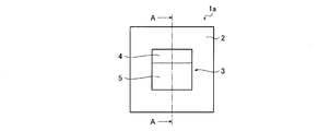
- FIG. 1 is a schematic top view showing an example of a flexographic printing plate according to the present invention.
- 2A is a cross-sectional view taken along the line AA of the flexographic printing plate shown in FIG. 1, and FIG. 2B conceptually shows an image printed using the flexographic printing plate of FIG. FIG.
- It is a schematic sectional drawing which shows another example of the flexographic printing plate of this invention.
- It is a schematic sectional drawing which shows another example of the flexographic printing plate of this invention.
- FIG. 5 (A) is a schematic top view showing another example of the flexographic printing plate of the present invention
- FIG. 5 (B) is a cross-sectional view taken along the line BB of FIG. 5 (A).
- FIG. 8A is a schematic cross-sectional view showing a conventional flexographic printing plate
- FIG. 8B is a diagram conceptually showing an image printed using the flexographic printing plate of FIG. 8A. .
- a numerical range expressed using “to” means a range including numerical values described before and after “to” as a lower limit value and an upper limit value.
- the flexographic printing plate according to the present invention (hereinafter, also simply referred to as “printing plate”) has a small dot constituting a highlight halftone dot portion in a highlight halftone dot portion having a dot area ratio of more than 0% and not more than 10%.
- at least one height of the small dots adjacent to the non-image portion that is continuous by 10 mm or more in the direction away from the edge of the highlight halftone dot portion is the average value of the heights of the small dots of the highlight halftone dot portion.
- Lower flexographic printing plate the configuration of the flexographic printing plate according to the present invention will be described in detail with reference to the accompanying drawings.
- FIG. 1 is a top view schematically showing an example of a flexographic printing plate according to the present invention
- FIG. 2 (A) is an enlarged view showing a part of a cross-sectional view taken along line AA of FIG.
- FIG. 2B conceptually shows an image printed using the flexographic printing plate shown in FIG.
- points first point 51, second point 52, and third point 53
- the ink is transferred by the small dots (first small dot 11, second small dot 12, and third small dot 13) at positions corresponding to the directions.
- a printing plate 1 a that is an example of a flexographic printing plate according to the present invention includes an image portion 3 and a non-image portion 2.
- the image portion 3 is an area where ink is applied at the time of printing and this ink is transferred to the printing material, that is, an image is formed at the time of printing.
- the non-image portion 2 is a region where ink is not applied during printing, that is, an image is not formed.
- the image portion 3 is composed of a solid portion to be printed and / or a large number of convex small dots by transferring ink entirely, and by changing the size and density of the small dots.
- the small dots constituting the halftone dot portion are usually formed with a predetermined screen line number (definition), for example, a screen line number of about 100 to 175 lpi (line per inch).
- the image portion 3 of the printing plate 1a which is the flexographic printing plate of the present invention has a highlight halftone dot portion 4 having a dot area ratio of more than 0% and not more than 10%.
- the image portion 3 above the broken line in the figure is the highlight halftone dot portion 4, and the image portion 3 below the broken line has a dot area ratio of more than 10% and not more than 100%.
- the highlight halftone dot portion 4 is adjacent to the non-image portion 2 that is continuous by 10 mm or more in a direction perpendicular to the edge side of the highlight halftone dot portion 4 and away from this edge side.
- the height of at least one of the small dots is lower than the average value of the heights of the small dots of the highlight halftone dot portion 4.
- FIG. 2A is an enlarged cross-sectional view of a boundary portion between the non-image portion 2 and the highlight halftone dot portion 4.
- the highlight halftone dot portion 4 has a large number of small dots constituting the halftone dot, and is adjacent to the non-image portion 2 (hereinafter referred to as a second small dot).
- a small point adjacent to the second small point 12 that is, a small point (hereinafter referred to as a third small point) 13 at the position of the second column from the non-image portion 2 side, It is formed lower than the height of the first small point 11, which is a small point other than the second small point 12 and the third small point 13.
- the 1st small point 11 which is small points other than the 2nd small point 12 and the 3rd small point 13 is formed in the same height.
- the small dot closest to the center of the highlight halftone dot portion 4 is the first small dot 11. Therefore, the second small point 12 and the third small point 13 are formed lower than the height of the small point closest to the center. Therefore, the second small point 12 and the third small point 13 are lower than the average value of the heights of all the small dots of the highlight halftone dot portion 4.
- FIG. 8A shows a schematic cross-sectional view of an example of a conventional flexographic printing plate
- FIG. 8B shows a conceptual diagram of an image printed using the flexographic printing plate of FIG. 8A.
- points first point 151, second point 152, and third point 153 formed on the substrate 150 are respectively left and right in FIG. 8A.
- the ink is transferred by the small dots (first small dots 111, second small dots 112, and third small dots 113) at positions corresponding to the directions.
- a conventional flexographic printing plate forms a highlight halftone dot portion in a highlight halftone dot portion having a dot area ratio of more than 0% and not more than 10%.
- the height of all the dots is uniform. That is, the second small point 112 adjacent to the non-image part 102 and the height of the third small point 113 at the position of the second column from the non-image part 102 side and the height of the other first small point 111 Are the same.
- the flexographic printing plate 100 is formed of a flexible material made of resin or rubber, when printing is performed using such a printing plate 100, the second small dots 112 in the vicinity of the non-image portion 102, A phenomenon occurs in which the printing pressure concentrates on the third small point 113 and the small point is crushed and fattened.
- the ink attached to the second small dots 112 adjacent to the non-image portion 102 or the third small dots 113 near the non-image portion 102 is printed on the substrate 150.
- the size of the second point 152 and the third point 153 formed by being transferred to the first point is the first point formed by being transferred from the first small point 111 at a position separated from the non-image portion 102. It becomes larger than the size of the point 151. Due to the phenomenon that the small dots adjacent to the non-image part become thicker, the highlight part and the non-image part are connected. Discontinuity of the image, so-called tone jump occurs.
- the printing plate 1 which is the flexographic printing plate of the present invention includes a second dot 12 adjacent to the non-image portion 2 among the small dots constituting the highlight halftone dot portion 4, and a non-image.
- the height of the third small dots 13 at the position of the second row from the portion 2 side is formed lower than the average value of the heights of the small dots of the highlight halftone dot portion 4. Therefore, when printing is performed using the printing plate 1, it is possible to suppress the printing pressure from being concentrated on the second small point 12 and the third small point 13 in the vicinity of the non-image portion 2. It is possible to suppress the phenomenon that the small dots of the image are crushed and fattened. Therefore, as shown in FIG.
- the ink attached to the second small dots 12 adjacent to the non-image portion 2 or the third small dots 13 in the vicinity of the non-image portion 2 is printed on the substrate 50.
- the size of the second point 52 and the third point 53 formed by being transferred to the first point 52 is determined by being transferred from the first small point 11 at a position separated from the non-image portion 2.
- the size can be the same as the size of the point 51. Thereby, it is possible to suppress the occurrence of a tone jump at the rising edge of the gradation, that is, the connection between the highlight portion and the non-image portion.
- the height of the small point is a height from the bottom between the small points.
- the difference L2 between the average height H1 of the small dots in the highlight halftone dot portion 4 and the height H2 of the second small dot 12 is the average value H1 of the heights of the small dots in the highlight halftone dot portion 4. Is preferably 5 to 70%. Setting the height difference L2 to 5% or more of H1 is preferable because printing pressure can be prevented from concentrating on the second small point 12 during printing. Further, by setting the height difference L2 to be 70% or more of H1, the second small point 12 can be surely pressed against the substrate 50, and it is preferable in terms of preventing the occurrence of missing. .
- the height difference L2 is more preferably 6 to 65%, and particularly preferably 10 to 60%, of the average height H1 of the small dots in the highlight halftone dot portion 4.
- the difference in the height of the small dots from the average value of the heights of the small dots is also referred to as “low layer formation amount”. It is also referred to as “low layer formation amount”.
- the average value H1 of the heights of the small dots in the highlight halftone dot portion 4 is substantially equal to the first small dots 11 that are small dots other than the small dots in the vicinity of the non-image portion 2. Accordingly, it can be said that the second small point 12 and the third small point 13 are lower in height than the small point closest to the center of the highlight halftone dot portion 4.
- the height of the first small dot in the flexographic printing plate is about 100 to 150 ⁇ m. Therefore, the average value H1 of the heights of the small dots in the highlight halftone dot portion 4 is substantially equal to the first small dots 11 other than the small dots in the vicinity of the non-image portion 2, and is about 100 to 150 ⁇ m. It is.
- the bottom of the region between the small points has a height different from that of the surface of the non-image portion 2, but this is not a limitation, and there is no limitation between the small points.
- the height of the bottom of the region may be flush with the height of the surface of the non-image portion 2.
- the second small dots 12 adjacent to the non-image portion 2 and the third small dots 13 in the second row position from the non-image portion 2 side are lowered.
- the present invention is not limited to this.
- the small dots in the third and subsequent columns from the non-image portion 2 may be further lowered.
- the amount of lowering is also 5 to 70% of the average value H1 of the heights of the small dots in the highlight halftone dot portion 4. preferable.
- the difference L3 between the average height H1 of the small dots of the highlight halftone dot portion 4 and the height H3 of the third small dot 13 is the highlight halftone dot portion 4. It is preferably 5 to 70% of the average value H1 of the heights of the small dots.
- the lower dots be closer to the non-image portion 2, and the second small dots adjacent to the non-image portion 2 are formed. It is preferable that the height be the lowest among the small dots of the highlight halftone dot portion 4.
- the second small dots 12 adjacent to the non-image portion 2 are formed lower than the third small dots 13 in the second row from the non-image portion 2. Yes.
- the lowering amount of the small dots in the second and subsequent rows is set to the lowering amount of the second small dots 12 adjacent to the non-image portion 2.
- the height of the second small dots 12 adjacent to the non-image portion 2 may be the same as the height of the third small dots 13 in the second row. .
- At least one small dot among the small dots adjacent to the non-image portion 2 that is continuous by 10 mm or more in the direction away from the edge of the highlight halftone dot portion 4 in the highlight halftone dot portion 4. May be formed lower than the average value of the heights of the small dots of the highlight halftone dot part 4, but the non-image part 2 continuous for 10 mm or more in the direction away from the edge of the highlight halftone dot part 4 and All of the adjacent small dots are preferably formed lower than the average value of the heights of the small dots of the highlight halftone dot portion 4. Thereby, it can suppress more suitably that a printing pressure concentrates on the 2nd small point 12 adjacent to the non-image part 2.
- the diameters of the tips of the small dots are the same, but the present invention is not limited to this. You may make smaller than the average value of the tip diameter of the small dot of a light halftone dot part. Further, the tip diameters of the low-pitched small dots other than the small dots adjacent to the non-image part may be smaller than the average value of the tip diameters of the small dots in the highlight halftone dot part.
- FIG. 4 shows a schematic cross-sectional view of another example of the flexographic printing plate of the present invention.
- the heights of the second small dots 12 adjacent to the non-image portion 2 and the third small dots 13 in the second row position from the non-image portion 2 side are the center. It is formed lower than the height of the 1st small point 11 which is a small point other than this including the closest point.
- the tip diameter d2 of the second small point 12 and the tip diameter d3 of the third small point 13 are smaller than the tip diameter d1 of the first small point. That is, the tip diameters of the second small point 12 and the third small point 13 that have been lowered are smaller than the average value of the tip diameters of the small dots of the highlight halftone dot portion 4.
- the printing pressure is concentrated on the small dots on the non-image portion 2 side by making the tip diameter of the small dots to be lowered lower than the average value of the tip diameters of the highlight dot portions. Even if the phenomenon that these small dots are crushed and fattened occurs, the size of the dots that are printed and formed on the substrate can be made the same size as the dots formed by the other small dots. .
- the tip diameter d2 of the second small point 12 and the tip diameter d3 of the third small point 13 are based on the tip diameter d1 of the first small point 11, printing conditions such as printing pressure, and the like. May be set as appropriate. Preferably, it is 25 to 60% of the first tip diameter d1.
- the tip diameter of the small point is a diameter at a position of 5 ⁇ m from the top of the small point. Further, when the shape of the small dot in the cross section perpendicular to the height direction is other than a circle, the diameter of the circle having the same circular area as that of the cross section (equivalent circle diameter) is defined as the tip diameter.
- the cross-sectional shape of the small dots in the cross-section parallel to the height direction of the small dots is a trapezoidal shape, but is not limited thereto, and is rectangular or corrugated. Or the like.
- the cross-sectional shape of the small dots in the cross-section perpendicular to the height direction of the small dots may be any shape such as a circular shape, an elliptical shape, a rectangular shape, a triangular shape, or a polygonal shape.
- the small dots for lowering the layer are small dots adjacent to a non-image portion that continues for 10 mm or more in a direction away from the edge of the highlight halftone dot portion. That is, when the length of the adjacent non-image part is less than 10 mm, the lowering of the small dots adjacent to the non-image part is not performed. This point will be described with reference to FIGS. 5A and 5B. In the following description, the length of the non-image portion in the direction away from the edge of the highlight halftone dot portion is also simply referred to as “length of the non-image portion”.
- FIG. 5 (A) is a top view conceptually showing another example of the flexographic printing plate of the present invention
- FIG. 5 (B) is a cross-sectional view taken along the line BB of FIG. 5 (A).
- a printing plate 1b shown in FIG. 5A has three image portions and a non-image portion 2, and each of the image portions is a highlight halftone dot portion having a dot area ratio of more than 0% and not more than 10%. 4a to 4c.
- the highlight halftone dot portions 4a to 4c are provided so as to be arranged in the vertical direction in the drawing, separated from each other by a predetermined distance.
- the distance t1 between the highlight halftone dot portion 4a arranged on the upper side in the drawing and the highlight halftone dot portion 4b arranged in the middle is less than 10 mm.
- the distance t2 between the highlight halftone dot portion 4b arranged in the middle of the figure and the highlight halftone dot portion 4c arranged on the lower side is 10 mm or more. Therefore, the small dots constituting the lower edge of the highlight halftone dot portion 4b and the small dots constituting the upper edge of the highlight halftone dot portion 4c are Since the small dots are adjacent to the non-image portion that is continuous by 10 mm or more in the direction away from the end side, the second small points 12 that are adjacent to the non-image portion 2 and 2 as shown in FIG. The third small point 13 in the row is lowered.
- the small dots constituting the lower edge of the highlight halftone dot portion 4a and the small dots constituting the upper edge of the highlight halftone dot portion 4b are adjacent to the non-image portion 2.
- the lower layer When the lower layer is applied to the small dots adjacent to the non-image part having a length of less than 10 mm, in other words, when the gap between the image parts is less than 10 mm, the lower layer is applied to the small dot adjacent to the non-image part. If printing is performed, a sufficient printing pressure is not applied to the low-layered small spots, and there is a possibility that missing may occur during printing. Therefore, in the present invention, the lower layer is reduced for the small dots adjacent to the non-image portion having a length of 10 mm or more, and the small dots adjacent to the non-image portion having a length of less than 10 mm are thus obtained.
- the above flexographic printing plate manufacturing method includes removing a hardened layer in a non-image part by engraving a hardened layer (relief forming layer) of a flexographic printing plate precursor by laser engraving, thereby forming a convex image part. Further, in the image portion, the hardened layer is removed in accordance with a predetermined number of screen lines and a desired halftone dot area ratio to form a large number of small dots to form a halftone dot portion.
- the small dot adjacent to the non-image portion having a length of 10 mm or more may be lowered.
- original image data of a printing plate to be produced is acquired, and this original image data is converted into data for laser engraving. Processor) processing.
- small dots in the vicinity of the non-image portion including small points adjacent to the non-image portion having a length of 10 mm or more are extracted from each image portion in the highlight halftone dot portion.
- a mask is generated by superimposing a template of a pattern that imparts a predetermined lowering amount on each extracted small point. At this time, the template is selected so that the lower layer amount is larger as the small point is on the non-image portion side.
- output image data is generated by multiplying the RIP processed image data by the generated mask.
- the output image data is generated by adding the pattern for giving the low layer amount to the small dots adjacent to the non-image portion of the highlight halftone dot portion in the image portion of the original image data.
- Laser engraving is performed using the data to produce a flexographic printing plate.
- the laser engraving method is basically the same as the laser engraving method used in the conventional flexographic printing plate manufacturing method.
- the output image data is output from the exposure head toward the printing plate precursor by winding a drum-shaped printing plate precursor on a cylindrical drum and rotating the drum.
- the type of laser used in laser engraving is not particularly limited, but an infrared laser is preferably used.
- an infrared laser When irradiated with an infrared laser, the molecules in the cured layer undergo molecular vibrations and generate heat.
- a high-power laser such as a carbon dioxide laser or YAG (Yttrium Aluminum Garnet) laser is used as an infrared laser, a large amount of heat is generated in the laser irradiation area, and molecules in the cured layer are selectively cut by molecular cutting or ionization. Removal, ie engraving.
- the advantage of laser engraving is that the engraving depth can be set arbitrarily, so that the structure can be controlled three-dimensionally.
- a portion that prints fine halftone dots can be engraved shallowly or with a shoulder so that the relief does not fall down due to printing pressure, and a portion of a groove that prints fine punched characters is engraved deeply As a result, the ink is less likely to be buried in the groove, and it is possible to suppress the crushing of the extracted characters.
- the cured layer when engraving with an infrared laser corresponding to the absorption wavelength of the photothermal conversion agent, the cured layer can be selectively removed with higher sensitivity, and a relief layer having a sharp image can be obtained.
- the infrared laser a carbon dioxide laser (CO 2 laser) or a semiconductor laser is preferable from the viewpoint of productivity, cost, and the like, and a semiconductor infrared laser with a fiber (FC-LD) is particularly preferable.
- a semiconductor laser can be downsized with high efficiency and low cost in laser oscillation compared to a CO 2 laser. Moreover, since it is small, it is easy to form an array. Furthermore, the beam shape can be controlled by processing the fiber.
- the semiconductor laser preferably has a wavelength of 700 to 1,300 nm, more preferably 800 to 1,200 nm, still more preferably 860 to 1,200 nm, and particularly preferably 900 to 1,100 nm.
- a semiconductor laser with a fiber is effective for laser engraving because it can efficiently output laser light by further attaching an optical fiber.
- the beam shape can be controlled by processing the fiber.
- the beam profile can have a top hat shape, and energy can be stably given to the plate surface. Details of the semiconductor laser are described in “Laser Handbook 2nd Edition” edited by Laser Society, “Practical Laser Technology” edited by IEICE. Further, the plate making apparatus provided with the fiber-coupled semiconductor laser described in detail in JP-A-2009-172658 and JP-A-2009-214334 can be suitably used in the method for producing a flexographic printing plate of the present invention. it can.
- the method for producing a flexographic printing plate is not limited to laser engraving (DLE (Direct Laser Engraving) method), and LAMS (Laser Laser Masking System) that writes and develops an image on the surface of the printing plate precursor with a laser. )
- DLE Direct Laser Engraving
- LAMS Laser Laser Masking System
- Various known manufacturing methods such as a method can be used.
- the flexographic printing plate precursor used in the present invention is not particularly limited as long as it is a known resin plate or rubber plate for flexographic printing. Further, the printing plate precursor may be a sheet or a cylinder. The printing plate precursor preferably has the following resin sheet as a cured layer (relief forming layer).
- a curable resin composition containing at least a polymer having a monomer unit derived from a diene hydrocarbon (hereinafter, also referred to as “resin composition for forming a resin sheet”) is formed into a sheet shape. It is preferably a sheet cured by the action of heat and / or light later, and more preferably formed by a resin composition for forming a resin sheet to be described later.
- the resin sheet is preferably capable of laser engraving.
- a resin composition for forming a resin sheet is prepared, and if necessary, after removing the solvent from the resin composition, it is melt-extruded on a support, or for resin sheet formation.
- a preferred example is a method of molding the composition into a sheet.
- the calendar roll 60 has first to fourth rolls 62a to 62d, and the interval between the rolls, the temperature of the rolls, and the rotation speed of the rolls can be set.
- the kneaded material 70 is set between the rolls, and the resin sheet 71 can be obtained by rolling.
- the material used for the support is not particularly limited as long as it can be mounted on a printing cylinder, but a material with high dimensional stability is preferably used.
- Metals such as steel, stainless steel and aluminum, polyesters (eg PET (polyethylene terephthalate), PBT (polybutylene terephthalate), PAN (polyacrylonitrile)) and plastic resins such as polyvinyl chloride, synthetic rubbers such as styrene-butadiene rubber, glass Examples thereof include plastic resins reinforced with fibers (such as epoxy resins and phenol resins).
- a PET film or a steel substrate is preferably used as the support.
- the resin composition for forming a resin sheet used in the present invention is obtained by, for example, dissolving or dispersing a polymer having a monomer unit derived from a diene hydrocarbon, a polymerizable compound, a fragrance, a plasticizer, and the like in an appropriate solvent, Subsequently, it can manufacture by dissolving a crosslinking agent, a polymerization initiator, a crosslinking accelerator, etc. From the viewpoints of ease of formation of the resin sheet, thickness accuracy of the obtained cylindrical printing plate precursor, and handling of the resin sheet, at least a part of the solvent component is preferably almost all of the cylindrical printing plate precursor. Since it is necessary to remove at the stage of production, an organic solvent having moderate volatility is preferable as the solvent.
- the resin sheet used in the present invention preferably contains a polymer having a monomer unit derived from a diene hydrocarbon (hereinafter, also referred to as “specific polymer”) as an essential component.
- the weight average molecular weight of the specific polymer is preferably from 5,000 to 1,600,000, more preferably from 10,000 to 1,000,000, and even more preferably from 15,000 to 600,000.
- the weight average molecular weight is 50,000 or more, the form retainability as a single resin is excellent, and when it is 1.6 million or less, it is easy to dissolve in a solvent and it is convenient for preparing a resin composition for laser engraving.
- the weight average molecular weight is measured by a gel permeation chromatography (GPC) method and is determined by conversion with standard polystyrene.
- GPC uses HLC-8220GPC (manufactured by Tosoh Corporation) and three columns of TSKgeL SuperHZM-H, TSKgeL SuperHZ4000, TSKgeL SuperHZ2000 (manufactured by Tosoh Corporation, 4.6 mm ID ⁇ 15 cm).
- THF tetrahydrofuran
- the conditions are as follows: the sample concentration is 0.35 mass%, the flow rate is 0.35 ml / min, the sample injection amount is 10 ⁇ L, the measurement temperature is 40 ° C., and an IR detector is used.
- the calibration curve is “Standard sample TSK standard, polystyrene” manufactured by Tosoh Corporation: “F-40”, “F-20”, “F-4”, “F-1”, “A-5000”, “ It is prepared from 8 samples of “A-2500”, “A-1000” and “n-propylbenzene”.
- the specific polymer may be a specific polymer having a monomer unit derived from a non-conjugated diene hydrocarbon, but is preferably a specific polymer having a monomer unit derived from a conjugated diene hydrocarbon.
- Specific polymers having monomer units derived from conjugated diene hydrocarbons include polymers obtained by polymerizing conjugated diene hydrocarbons, conjugated diene hydrocarbons and other unsaturated compounds, preferably mono Preferred examples include copolymers obtained by polymerizing olefinic unsaturated compounds.
- the above polymers and copolymers may be modified, for example, a reactive group such as a (meth) acryloyl group may be introduced at the end, and a part of the internal olefin is hydrogenated. May be.
- polybutadiene in which part of the internal olefin is hydrogenated is also referred to as “partially hydrogenated polybutadiene”, and similarly, polyisoprene in which part of the internal olefin is hydrogenated is also referred to as “partially hydrogenated polyisoprene”.
- the copolymer may be a random polymer, a block copolymer, or a graft polymer, and is not particularly limited.
- conjugated diene hydrocarbons include 1,3-butadiene and isoprene. These compounds are used alone or in combination of two or more.
- monoolefin unsaturated compound include styrene, ⁇ -methylstyrene, o-methylstyrene, p-methylstyrene, isobutene, vinyl chloride, vinylidene chloride, (meth) acrylamide, (meta ) Acrylamide vinyl acetate, (meth) acrylic acid ester, (meth) acrylic acid and the like.
- the polymer obtained by polymerizing the conjugated diene hydrocarbon or the copolymer obtained by polymerizing the conjugated diene hydrocarbon and the monoolefin unsaturated compound is not particularly limited, and specifically, Butadiene polymer, isoprene polymer, styrene-butadiene copolymer, styrene-isoprene copolymer, acrylate ester-isoprene copolymer, methacrylic acid ester and conjugated diene copolymer, acrylonitrile-butadiene-styrene copolymer Examples thereof include styrene-isoprene-styrene block copolymer, styrene-butadiene-styrene block copolymer, and isobutene-isoprene copolymer (butyl rubber). These polymers may be emulsion-polymerized or solution-polymerized.
- the specific polymer may have an ethylenically unsaturated group at the terminal, or may have a partial structure represented by the following formula (A-1).
- R 1 represents a hydrogen atom or a methyl group
- A represents O or NH
- * represents a bonding position with another structure.
- A is preferably O. That is, the specific polymer may have a (meth) acryloyloxy group or a (meth) acrylamide group in the molecule, and more preferably has a (meth) acryloyloxy group.
- the specific polymer may have the partial structure represented by the formula (A-1) at either the main chain terminal or the side chain, but preferably has the main chain terminal. From the viewpoint of printing durability, the specific polymer preferably has two or more partial structures represented by the formula (A-1) in the molecule.
- Specific polymers having a partial structure represented by the formula (A-1) include polybutadiene di (meth) acrylate, partially hydrogenated polybutadiene di (meth) acrylate, polyisoprene (meth) acrylate, and partially hydrogenated polyisoprene.
- a polyolefin (meth) acrylate obtained by reacting an ethylenically unsaturated group-containing compound with a hydroxyl group of a hydroxyl group-containing polyolefin such as (meth) acrylate (for example, BAC-45 (manufactured by Osaka Organic Chemical Industry Co., Ltd.), TEA-1000) , TE-2000, EMA-3000 (manufactured by Nippon Soda Co., Ltd.)).
- BAC-45 manufactured by Osaka Organic Chemical Industry Co., Ltd.
- TEA-1000 TE-2000
- EMA-3000 manufactured by Nippon Soda Co., Ltd.
- modified polyolefins in which an ethylenically unsaturated bond is introduced by modifying the polyolefin for example, methacrylate-introduced polyisoprene (Kuraprene UC-203, UC-102 (manufactured by Kuraray Co., Ltd.) are also preferred.
- the specific polymer is preferably a polymer having monomer units derived from butadiene and / or isoprene.
- polybutadiene butadiene rubber
- partially hydrogenated polybutadiene terminal-modified polybutadiene
- polyisoprene isoprene rubber
- partially hydrogenated polyisoprene terminal-modified polyisoprene
- SBR styrene-butadiene rubber
- SBS styrene- Examples thereof include butadiene-styrene triblock copolymer
- ABS acrylonitrile-butadiene-styrene copolymer
- SIS styrene-isoprene-styrene triblock copolymer
- the terminal modification means that the main chain or side chain terminal is modified with an amide group, a carboxy group, a hydroxy group, a (meth) acryloyl group, a glycidyl group, or the like.
- polybutadiene, partially hydrogenated polybutadiene, hydroxyl-terminated polybutadiene, glycidyl ether-modified polybutadiene, polyisoprene, partially hydrogenated polyisoprene, terminal-modified polyisoprene, hydroxyl-terminated polyisoprene, glycidyl ether-modified polyisoprene, SBS, and SIS are preferable. .
- the proportion of monomer units derived from butadiene, isoprene or hydrogenated product thereof is preferably 30 mol% or more in total, more preferably 50 mol% or more, and further preferably 80 mol% or more. preferable.
- Isoprene is known to polymerize by 1,2-, 3,4- or 1,4-addition depending on the catalyst and reaction conditions.
- polyisoprene polymerized by any of the above additions is known. But you can.
- the content of cis-1,4-polyisoprene is preferably 50% by mass or more, more preferably 65% by mass or more, and 80% by mass or more. More preferably, it is particularly preferably 90% by mass or more.
- polyisoprene natural rubber may be used, and commercially available polyisoprene can also be used.
- NIPOL IR series manufactured by Nippon Zeon Co., Ltd.
- Nippon Zeon Co., Ltd. is exemplified.
- butadiene is known to be polymerized by 1,2- or 1,4-addition depending on the catalyst and reaction conditions, but polybutadiene polymerized by any of the above additions may be used in the present invention.
- 1,4-polybutadiene is a main component.
- the content of 1,4-polybutadiene is preferably 50% by mass or more, more preferably 65% by mass or more, and further preferably 80% by mass or more. It is preferably 90% by mass or more.
- the content of the cis body and the trans body is not particularly limited, but from the viewpoint of developing rubber elasticity, the cis body is preferable, and the content of cis-1,4-polybutadiene is preferably 50% by mass or more. , 65% by mass or more, more preferably 80% by mass or more, and particularly preferably 90% by mass or more.
- the polybutadiene commercially available products may be used, and examples thereof include the NIPOL BR series (manufactured by Zeon Corporation) and the UBEPOL BR series (manufactured by Ube Industries).
- the specific polymer may be a specific polymer having a monomer unit derived from a non-conjugated diene hydrocarbon.
- Preferred examples of the specific polymer include a copolymer obtained by polymerizing a nonconjugated diene hydrocarbon and another unsaturated compound, preferably an ⁇ -olefinic unsaturated compound.
- the copolymer may be a random polymer, a block copolymer, or a graft polymer, and is not particularly limited.
- non-conjugated diene hydrocarbons include dicyclopentadiene, 1,4-hexadiene, cyclooctadiene, methylene norbornene, ethylidene norbornene, and dicyclopentadiene and ethylidene norbornene are preferable. Ethylidene norbornene is more preferable. These compounds are used alone or in combination of two or more.
- Specific examples of the monoolefin unsaturated compound include ⁇ -olefins having 2 to 20 carbon atoms such as ethylene, propylene, 1-butene, 1-hexene, 4-methyl-pentene, and the like. Ethylene and propylene are preferable, and a combination of ethylene and propylene is more preferable. These compounds are used alone or in combination of two or more.
- a polymer obtained by polymerizing the above conjugated diene hydrocarbon or a copolymer obtained by polymerizing a conjugated diene hydrocarbon and an ⁇ -olefin unsaturated compound is not particularly limited, but ethylene- ⁇ An olefin-diene copolymer is preferred, and ethylene-propylene-diene rubber (EPDM) is more preferred.
- the specific polymer is preferably styrene-butadiene rubber, butadiene rubber, isoprene rubber, or ethylene-propylene-diene rubber, and more preferably butadiene rubber.
- the specific polymer is preferably a polymer whose main chain mainly contains isoprene or butadiene as a monomer unit, and a part thereof may be hydrogenated to be converted to a saturated bond.
- the main chain or the terminal of the polymer may be modified with an amide, a carboxy group, a hydroxy group, a (meth) acryloyl group or the like, or may be epoxidized.
- the specific polymer is preferably exemplified by polybutadiene, polyisoprene, and isoprene / butadiene copolymer from the viewpoint of solubility in a solvent and handling, polybutadiene and polyisoprene are more preferable, and polybutadiene is more preferable.
- the specific polymer preferably has a glass transition temperature (Tg) of 20 ° C. or less from the viewpoint of flexibility and rubber elasticity.
- Tg glass transition temperature
- the glass transition temperature of the specific polymer is measured according to JIS K7121-1987 using a differential scanning calorimeter (DSC).
- DSC differential scanning calorimeter
- a specific polymer has two or more glass transition temperatures, it is preferable that at least one is 20 degrees C or less, and it is more preferable that all the glass transition temperatures are 20 degrees C or less.
- the specific polymer preferably has an SP value of 14.0 to 18.0 MPa 1/2 , more preferably 15.0 to 17.5 MPa 1/2 , and 16.0 to 17.5 MPa. More preferably, it is 1/2 .
- the SP value is the square root of the cohesive energy density of molecules, and represents the magnitude of the cohesive force between molecules, and is a measure of polarity. It is preferable for the SP value to be in the above-mentioned range because moderate adhesiveness with a urethane-based adhesive can be obtained.
- the SP value is calculated based on the Okitsu method described in Journal of the Japan Adhesion Society 29 (3) 1993, 204-211.
- the specific polymer is preferably an elastomer or a plastomer.
- the specific polymer is an elastomer or a plastomer, good thickness accuracy and dimensional accuracy can be achieved when the printing plate precursor for laser engraving obtained therefrom is formed into a sheet or cylinder.
- plastomer means that it is easily deformed by heating and deformed by cooling, as described in “New edition polymer dictionary” edited by the Society of Polymer Science, Japan (Asakura Shoten, published in 1988). It means a polymer having the property that it can be solidified into a shaped shape.
- Plastomer is a term for an elastomer (having the property of instantly deforming according to the external force when an external force is applied and restoring the original shape in a short time when the external force is removed). It does not show such elastic deformation and easily plastically deforms.
- the plastomer can be deformed to 200% with a small external force at room temperature (20 ° C.) when the original size is 100%, and does not return to 130% or less even when the external force is removed.
- the small external force specifically refers to an external force having a tensile strength of 1 to 100 MPa. More specifically, based on the tensile permanent strain test of JIS K 6262-1997, when the dumbbell-shaped No.
- test piece specified in JIS K 6251-1993 was used, the above test piece was subjected to a tensile test at 20 ° C. It is possible to stretch without breaking to twice the distance between the marked lines before tensioning, and after holding for 60 minutes when the distance between the marked lines before tension is extended to twice the distance between the marked lines, 5 It means a polymer having a tensile set of 30% or more after a minute.
- all of the test pieces are JIS K 6262 except that the test piece is dumbbell-shaped No. 4 defined in JIS K6251-1993, the holding time is 60 minutes, and the temperature of the test chamber is 20 ° C. Compliant with the 1997 tensile set test method.
- the plastomer has a polymer glass transition temperature (Tg) of less than 20 ° C. In the case of a polymer having two or more Tg, all Tg is less than 20 ° C.
- Tg polymer glass transition temperature
- an elastomer is a polymer that can be stretched to twice the distance between the marked lines in the above-described tensile test and that has a tensile set of less than 30% after 5 minutes excluding tensile external force.
- the viscosity of the specific polymer of the present invention at 20 ° C. is preferably 10 Pa ⁇ s to 10 kPa ⁇ s, more preferably 50 Pa ⁇ s to 5 kPa ⁇ s. When the viscosity is within this range, the resin composition can be easily formed into a sheet and the process is simple.
- a specific polymer is a plastomer, when shape
- the specific polymer may be used alone or in combination of two or more.
- the total content of the specific polymer in the resin sheet used in the present invention is preferably 5 to 90% by mass, more preferably 15 to 85% by mass, and further preferably 30 to 80% by mass with respect to the total solid content of the resin sheet. preferable.
- the total content of the specific polymer in the resin composition for forming a resin sheet used in the present invention is preferably 5 to 90% by mass, more preferably 15 to 85% by mass with respect to the total solid content of the resin composition. 30 to 80% by mass is more preferable.
- solid content total mass means the total mass remove
- the resin sheet and the resin composition for forming a resin sheet used in the present invention preferably contain a polymerization initiator, a photothermal conversion agent, a solvent, and other components. Hereinafter, these components will be described in detail.
- the resin composition for laser engraving is preferably formed using a resin composition for forming a resin sheet containing a polymerization initiator.
- a polymerization initiator By containing a polymerization initiator, the specific polymer and the crosslinking of the ethylenically unsaturated bonds contained in the polymerizable compound described later are promoted.
- the polymerization initiator those known to those skilled in the art can be used without limitation, and both a photopolymerization initiator and a thermal polymerization initiator can be used, but crosslinking can be formed with a simple apparatus.
- a thermal polymerization initiator is preferred.
- the radical polymerization initiator which is a preferable polymerization initiator is explained in full detail, this invention is not restrict
- preferred polymerization initiators include (a) aromatic ketones, (b) onium salt compounds, (c) organic peroxides, (d) thio compounds, (e) hexaarylbiimidazole compounds, f) ketoxime ester compounds, (g) borate compounds, (h) azinium compounds, (i) metallocene compounds, (j) active ester compounds, (k) compounds having a carbon halogen bond, (l) azo compounds, etc. Can be mentioned. Specific examples of the above (a) to (l) are given below, but the present invention is not limited to these.
- an organic peroxide and (l) an azo compound are more preferred from the viewpoint of engraving sensitivity and a good relief edge shape when applied to a resin sheet, and (c) an organic compound.
- Peroxides are particularly preferred.
- the compounds listed in paragraphs 0074 to 0118 of JP-A-2008-63554 are preferably used. it can.
- the organic peroxide and (l) the azo compound are preferably the following compounds.
- the organic peroxide (c) is particularly preferable as a polymerization initiator in the present invention from the viewpoint of improving the crosslinkability of the resin sheet and engraving sensitivity.
- an embodiment in which this (c) organic peroxide and a photothermal conversion agent described later are combined is particularly preferable.
- this effect is remarkable when using carbon black as a photothermal conversion agent. This is because (c) heat generated from carbon black is also transferred to organic peroxide, so heat is generated not only from carbon black but also from organic peroxide. This is because energy generation occurs synergistically.
- the polymerization initiator may be used alone or in combination of two or more.
- the content of the polymerization initiator in the resin sheet used in the present invention is preferably 0.01 to 30% by mass and more preferably 0.1 to 20% by mass with respect to the total mass of the solid content. Preferably, the content is 1 to 15%.
- the content of the polymerization initiator in the resin composition for forming a resin sheet used in the present invention is preferably 0.01 to 30% by mass, and preferably 0.1 to 20% by mass with respect to the total solid content. More preferably, it is 1 to 15%. It is preferable for the content to be in the above range since the curability (crosslinking property) is excellent, the relief edge shape is good when laser engraving is performed, and the rinse property is excellent.
- the resin sheet and the resin composition for forming a resin sheet used in the present invention preferably further contain a photothermal conversion agent. That is, it is considered that the photothermal conversion agent in the present invention promotes thermal decomposition of a cured product during laser engraving by absorbing laser light and generating heat. For this reason, it is preferable to select a photothermal conversion agent that absorbs light having a laser wavelength used for engraving.
- the resin sheet used in the present invention is used for laser engraving using a laser (YAG laser, semiconductor laser, fiber laser, surface emitting laser, etc.) emitting an infrared ray of 700 to 1,300 nm as a light source, It is preferable to use a compound having a maximum absorption wavelength at 700 to 1,300 nm.
- a laser YAG laser, semiconductor laser, fiber laser, surface emitting laser, etc.
- Various dyes or pigments are used as the photothermal conversion agent in the present invention.
- the dye commercially available dyes and known ones described in documents such as “Dye Handbook” (edited by the Society for Synthetic Organic Chemistry, published in 1970) can be used. Specific examples include those having a maximum absorption wavelength at 700 to 1,300 nm, such as azo dyes, metal complex azo dyes, pyrazolone azo dyes, naphthoquinone dyes, anthraquinone dyes, phthalocyanine dyes, carbonium dyes, diimmonium compounds, and quinoneimine dyes. Preferred are dyes such as methine dyes, cyanine dyes, squarylium dyes, pyrylium salts, metal thiolate complexes.
- Dyes preferably used in the present invention include cyanine dyes such as heptamethine cyanine dyes, oxonol dyes such as pentamethine oxonol dyes, phthalocyanine dyes, and paragraphs 0124 to 0137 of JP-A-2008-63554. Mention may be made of dyes.
- photothermal conversion agents used in the present invention
- commercially available pigments and color index (CI) manuals “latest pigment manuals” (edited by the Japan Pigment Technical Association, published in 1977), “latest pigment application”
- the pigments described in “Technology” (CMC Publishing, 1986) and “Printing Ink Technology” CMC Publishing, 1984) can be used.
- Examples of the pigment include pigments described in paragraphs 0122 to 0125 of JP2009-178869A. Of these pigments, carbon black is preferred.
- carbon black can be used regardless of the classification according to ASTM or the use (for example, for color, for rubber, for dry battery, etc.).
- Carbon black includes, for example, furnace black, thermal black, channel black, lamp black, acetylene black and the like.
- black colorants such as carbon black can be used as color chips or color pastes previously dispersed in nitrocellulose or a binder, if necessary. Such chips and pastes can be easily obtained as commercial products. Examples of carbon black include those described in paragraphs 0130 to 0134 of JP-A-2009-178869.
- Only 1 type may be used for the photothermal conversion agent in the resin sheet and resin composition for resin sheet formation used for this invention, and it may use 2 or more types together.
- the content of the photothermal conversion agent in the resin sheet varies greatly depending on the molecular extinction coefficient inherent to the molecule, but is preferably in the range of 0.01 to 30% by mass of the total solid content, and 0.05 to 20% by mass. % Is more preferable, and 0.1 to 10% by mass is particularly preferable.
- the content of the photothermal conversion agent in the resin composition for forming a resin sheet varies greatly depending on the molecular extinction coefficient inherent to the molecule, but is preferably in the range of 0.01 to 30% by mass of the total mass of the solid content. 0.05 to 20% by mass is more preferable, and 0.1 to 10% by mass is particularly preferable.
- the resin composition for forming a resin sheet used in the present invention may contain a solvent.
- a solvent an organic solvent is preferably used.
- Preferred specific examples of the aprotic organic solvent include acetonitrile, tetrahydrofuran, dioxane, toluene, propylene glycol monomethyl ether acetate, methyl ethyl ketone, acetone, methyl isobutyl ketone, ethyl acetate, butyl acetate, ethyl lactate, N, N-dimethylacetamide, N -Methylpyrrolidone, dimethyl sulfoxide.
- protic organic solvent examples include methanol, ethanol, 1-propanol, 2-propanol, 1-butanol, 1-methoxy-2-propanol, ethylene glycol, diethylene glycol, and 1,3-propanediol.
- propylene glycol monomethyl ether acetate is particularly preferable.
- additives Various known additives can be appropriately blended in the resin sheet and the resin composition for forming a resin sheet used in the present invention as long as the effects of the present invention are not impaired.
- a crosslinking agent, a crosslinking accelerator, a plasticizer, a filler, a wax, a process oil, a metal oxide, an antiozonation agent, an antiaging agent, a polymerization inhibitor, a coloring agent, and the like can be mentioned. Or two or more of them may be used in combination.
- the resin sheet used in the present invention can be formed by using a resin composition for forming a resin sheet containing a polymerizable compound in order to promote the formation of a crosslinked structure.
- a resin composition for forming a resin sheet containing a polymerizable compound By containing a polymerizable compound, formation of a crosslinked structure is promoted, and the resulting cylindrical printing plate is excellent in printing durability.
- the specific polymer having an ethylenically unsaturated group described above is not included in the polymerizable compound.
- the polymerizable compound is preferably a compound having a molecular weight of less than 3,000, and more preferably a compound having a molecular weight of less than 1,000.
- the polymerizable compound is preferably a radical polymerizable compound, and is preferably an ethylenically unsaturated compound.
- the polymerizable compound used in the present invention is preferably a polyfunctional ethylenically unsaturated compound. It is excellent in the printing durability of the cylindrical printing plate obtained as it is the said aspect.
- the polyfunctional ethylenically unsaturated compound is preferably a compound having 2 to 20 terminal ethylenically unsaturated groups. Such a compound group is widely known in this industrial field, and in the present invention, these can be used without any particular limitation.
- Examples of compounds derived from an ethylenically unsaturated group in a polyfunctional ethylenically unsaturated compound include unsaturated carboxylic acids (eg, acrylic acid, methacrylic acid, itaconic acid, crotonic acid, isocrotonic acid, maleic acid, etc.)
- unsaturated carboxylic acids eg, acrylic acid, methacrylic acid, itaconic acid, crotonic acid, isocrotonic acid, maleic acid, etc.
- Examples include esters and amides.
- esters of unsaturated carboxylic acids and aliphatic polyhydric alcohol compounds, and amides of unsaturated carboxylic acids and aliphatic polyvalent amine compounds are used.
- unsaturated carboxylic acid esters having nucleophilic substituents such as hydroxy groups and amino groups, amides and polyfunctional isocyanates, addition reaction products of epoxies, and dehydration condensation reaction products of polyfunctional carboxylic acids Etc. are also preferably used.
- an unsaturated carboxylic acid ester having an electrophilic substituent such as an isocyanato group or an epoxy group, an amide and a monofunctional or polyfunctional alcohol, an addition reaction product of an amine, a halogen group, a tosyloxy group, A substituted reaction product of unsaturated carboxylic acid ester, amide and monofunctional or polyfunctional alcohols or amines having a leaving substituent such as the above is also suitable.
- a compound group in which a vinyl compound, an allyl compound, an unsaturated phosphonic acid, styrene, or the like is substituted for the above unsaturated carboxylic acid can be used.
- the ethylenically unsaturated group contained in the polymerizable compound is preferably an acrylate, methacrylate, vinyl compound, or allyl compound residue from the viewpoint of reactivity. Further, from the viewpoint of printing durability, the polyfunctional ethylenically unsaturated compound preferably has 3 or more ethylenically unsaturated groups.
- the monomer of an ester of an aliphatic polyhydric alcohol compound and an unsaturated carboxylic acid include acrylic acid esters such as ethylene glycol diacrylate, diethylene glycol diacrylate, triethylene glycol diacrylate, polyethylene glycol diacrylate, 1, 3 -Butanediol diacrylate, tetramethylene glycol diacrylate, propylene glycol diacrylate, dipropylene glycol diacrylate, tripropylene glycol diacrylate, polypropylene glycol diacrylate, neopentyl glycol diacrylate, 1,6-hexanediol diacrylate, 1 , 4-cyclohexanediol diacrylate, tetraethylene glycol diacrylate, polytetramethyl Lenglycol diacrylate, 1,8-octanediol diacrylate, 1,9-nonanediol diacrylate, 1,10-decanediol diacrylate, tricyclodecan
- Methacrylic acid esters include tetramethylene glycol dimethacrylate, ethylene glycol dimethacrylate, diethylene glycol dimethacrylate, triethylene glycol dimethacrylate, polyethylene glycol dimethacrylate, propylene glycol dimethacrylate, dipropylene glycol dimethacrylate, tripropylene glycol dimethacrylate, polypropylene Glycol dimethacrylate, neopentyl glycol dimethacrylate, trimethylolpropane trimethacrylate, trimethylolethane trimethacrylate, 1,3-butanediol dimethacrylate, 1,6-hexanediol dimethacrylate, 1,8-octanediol dimethacrylate, 1 , 9-Nonanediol dimetac 1,10-decanediol dimethacrylate, pentaerythritol dimethacrylate, pentaeryth
- Itaconic acid esters include ethylene glycol diitaconate, propylene glycol diitaconate, 1,3-butanediol diitaconate, 1,4-butanediol diitaconate, tetramethylene glycol diitaconate, pentaerythritol diitaconate Sorbitol tetritaconate and the like.
- crotonic acid esters include ethylene glycol dicrotonate, tetramethylene glycol dicrotonate, pentaerythritol dicrotonate, and sorbitol tetracrotonate.
- isocrotonic acid esters examples include ethylene glycol diisocrotonate, pentaerythritol diisocrotonate, and sorbitol tetraisocrotonate.
- maleic acid esters examples include ethylene glycol dimaleate, triethylene glycol dimaleate, pentaerythritol dimaleate, and sorbitol tetramaleate.
- esters examples include aliphatic alcohol esters described in JP-B-46-27926, JP-B-51-47334, JP-A-57-196231, JP-A-59-5240, Those having an aromatic skeleton described in JP-A-59-5241 and JP-A-2-226149 and those containing an amino group described in JP-A-1-165613 are also preferably used.
- the above ester monomers can be used as a mixture.
- amide monomers of aliphatic polyvalent amine compounds and unsaturated carboxylic acids include methylene bisacrylamide, methylene bismethacrylamide, 1,6-hexamethylene bis-acrylamide, 1,6-hexamethylene bis.
- examples include methacrylamide, diethylenetriamine trisacrylamide, xylylene bisacrylamide, and xylylene bismethacrylamide.
- Examples of other preferable amide monomers include those having a cyclohexylene structure described in JP-B No. 54-21726.
- urethane-based addition polymerizable compounds produced by using an addition reaction of isocyanate and hydroxyl group are also suitable. Specific examples thereof include, for example, one molecule described in JP-B-48-41708.
- a vinyl urethane containing two or more polymerizable vinyl groups in one molecule obtained by adding a vinyl monomer containing a hydroxyl group represented by the following general formula (i) to a polyisocyanate compound having two or more isocyanato groups. Compounds and the like.
- CH 2 C (R) COOCH 2 CH (R ') OH (i) (However, R and R ′ each represent H or CH 3. )
- urethane acrylates such as those described in JP-A-51-37193, JP-B-2-32293, JP-B-2-16765, JP-B-58-49860, JP-B-56-17654 Urethane compounds having an ethylene oxide skeleton described in JP-B-62-39417 and JP-B-62-39418 are also suitable.
- vinyl compound examples include butanediol-1,4-divinyl ether, ethylene glycol divinyl ether, 1,2-propanediol divinyl ether, 1,3-propanediol divinyl ether, 1,3-butanediol divinyl ether, 1,4 -Butanediol divinyl ether, neopentyl glycol divinyl ether, trimethylolpropane trivinyl ether, trimethylol ethane trivinyl ether, hexanediol divinyl ether, tetraethylene glycol divinyl ether, pentaerythritol divinyl ether, pentaerythritol trivinyl ether, pentaerythritol tetravinyl ether, Sorbitol tetravinyl ether, sorbitol pentavinyl ether, ethylene glycol Rudi
- the resin sheet used for this invention and the resin composition used for the formation may use only 1 type of polymeric compounds, and may use 2 or more types together.
- the content of the polymerizable compound in the resin sheet used in the present invention is preferably 0.1 to 30% by mass, more preferably 0.5 to 20% by mass with respect to the total solid content of the resin composition. More preferred is 10% by mass.
- the content of the polymerizable compound in the resin composition for forming a resin sheet used in the present invention is preferably 0.1 to 30% by mass, and preferably 0.5 to 20% by mass with respect to the total solid content of the resin composition. Is more preferable, and 1 to 10% by mass is still more preferable. Within the above range, the rinsing property of engraving residue generated during laser engraving is excellent, and the printing durability of the obtained cylindrical printing plate is excellent.
- the total content of the specific polymer in the resin sheet is preferably 5 to 90% by mass and the content of the polymerization initiator is 0.01 to 30% by mass with respect to the total mass of the solid content of the resin sheet used in the present invention.
- the content of the photothermal conversion agent is preferably in the range of 0.01 to 30% by mass, and the content of the polymerizable compound is preferably 0 to 30% by mass.
- the total content of the specific polymer in the resin composition for forming a resin sheet is preferably 5 to 90% by mass with respect to the total solid content of the resin composition for forming a resin sheet used in the present invention.
- the content of is preferably 0.01 to 30% by mass
- the content of the photothermal conversion agent is preferably in the range of 0.01 to 30% by mass
- the content of the polymerizable compound is 0 to 30% by mass. % Is preferred.
- the resin sheet used in the present invention is preferably a sheet cured by the action of heat and / or light.
- the resin sheet used for this invention contains a photoinitiator, it can be hardened
- the light irradiation is preferably performed on the entire surface of the resin sheet. Examples of light include visible light, ultraviolet light, and electron beam, but ultraviolet light is most preferable.
- the support side of the resin sheet is the back side, the surface may only be irradiated with light. However, if the support is a transparent film that transmits light, it is preferable that the back side is further irradiated with light.
- the irradiation from the surface may be performed while the protective film is provided, or may be performed after the protective film is peeled off.
- light irradiation may be performed after the resin sheet is covered with a vinyl chloride sheet and evacuated.
- the resin sheet contains a thermal polymerization initiator (the above-mentioned photopolymerization initiator can also be a thermal polymerization initiator), it can be cured by heating the resin sheet (crosslinking by heat).
- the heating means for performing crosslinking by heat include a method of heating a resin sheet for a predetermined time in a hot air oven or a far infrared oven, and a method of contacting a heated roll for a predetermined time.
- crosslinking by heat is preferable from the viewpoint that the resin sheet can be uniformly cured (crosslinked) from the surface to the inside.
- crosslinking the resin sheet there is an advantage that firstly the relief formed after laser engraving becomes sharp, and secondly, the adhesiveness of engraving residue generated during laser engraving is suppressed.
- the manufacturing method of a flexographic printing plate may include the following rinse process, a drying process, and / or a post-crosslinking process as needed after the engraving process.
- Rinsing step a step of rinsing the engraved surface of the relief layer surface after engraving with water or a liquid containing water as a main component.
- Drying step a step of drying the engraved relief layer.
- Post-crosslinking step a step of imparting energy to the relief layer after engraving and further crosslinking the relief layer. Since the engraving residue is attached to the engraving surface after the engraving step, a rinsing step of rinsing the engraving residue by rinsing the engraving surface with water or a liquid containing water as a main component may be added.
- rinsing there is a method of washing with tap water, a method of spraying high-pressure water, and a known batch type or conveying type brush type washing machine as a photosensitive resin relief printing machine.
- a rinsing liquid to which soap or a surfactant is added may be used.
- a drying process for drying the engraved recording layer and volatilizing the rinsing liquid it is preferable to add a drying process for drying the engraved recording layer and volatilizing the rinsing liquid.
- a post-crosslinking step for further crosslinking the engraved recording layer may be added. By performing the post-crosslinking step, which is an additional cross-linking step, the relief formed by engraving can be further strengthened.
- the pH of the rinsing liquid used in the rinsing step is preferably 9 or more, more preferably 10 or more, and still more preferably 11 or more.
- the pH of the rinsing liquid is preferably 14 or less, more preferably 13.5 or less, and still more preferably 13.1 or less. Handling is easy in the said range. What is necessary is just to adjust pH using an acid and / or a base suitably in order to make a rinse liquid into said pH range, and the acid and base to be used are not specifically limited.
- a rinse liquid contains water as a main component.
- the rinse liquid may contain water miscible solvents, such as alcohol, acetone, tetrahydrofuran, etc. as solvents other than water.
- the rinse liquid contains a surfactant.
- surfactants betaines such as carboxybetaine compounds, sulfobetaine compounds, phosphobetaine compounds, amine oxide compounds, or phosphine oxide compounds from the viewpoint of reducing engraving residue removal and the effect on flexographic printing plates.
- Preferred examples include compounds (amphoteric surfactants).
- N O amine oxide compound
- the surfactant include known anionic surfactants, cationic surfactants, amphoteric surfactants, and nonionic surfactants.
- fluorine-based and silicone-based nonionic surfactants can be used in the same manner.
- Surfactant may be used individually by 1 type, or may use 2 or more types together.
- the amount of the surfactant used is not particularly limited, but is preferably 0.01 to 20% by mass, and more preferably 0.05 to 10% by mass with respect to the total mass of the rinsing liquid.
- the thickness of the relief layer (cured layer) of the prepared flexographic printing plate is preferably 0.05 mm or more and 10 mm or less from the viewpoint of satisfying various printability such as abrasion resistance and ink transferability. 05 mm or more and 7 mm or less are more preferable, and 0.05 mm or more and 3 mm or less are particularly preferable.
- the Shore A hardness of the relief layer which the produced flexographic printing plate has is 50 degree or more and 90 degrees or less.
- the Shore A hardness of the relief layer is 50 ° or more, even if the fine halftone dots formed by engraving are subjected to the strong printing pressure of the relief printing press, they do not collapse and can be printed normally.
- the Shore A hardness of the relief layer is 90 ° or less, it is possible to prevent faint printing in a solid portion even in flexographic printing with a kiss touch.
- the Shore A hardness in the present specification is a durometer (spring type) in which an indenter (called a push needle or indenter) is pushed and deformed on the surface of the object to be measured, and the amount of deformation (pushing depth) is measured and digitized. It is a value measured by a rubber hardness meter.
- the flexographic printing apparatus basically has the same configuration as that of the conventional flexographic printing apparatus except that the flexographic printing plate is used.
- FIG. 7 is a diagram conceptually showing a main part of a flexographic printing apparatus using the flexographic printing plate according to the present invention.
- the flexographic printing apparatus 30 includes the flexographic printing plate 1, a drum (plate cylinder) 31, a conveyance roller (impression cylinder) 32, an anilox roller 33, a doctor chamber 34, and a circulation tank 35.
- the drum 31 has a cylindrical shape, and the flexographic printing plate 1 is placed on the peripheral surface, and the flexographic printing plate 1 is brought into contact with the printing medium z while rotating.
- the conveyance roller 32 is a roller that constitutes a conveyance unit (not shown) that conveys the printing medium z along a predetermined conveyance path, and its circumferential surface is arranged to face the circumferential surface of the drum 31, The printed body z is brought into contact with the flexographic printing plate 1.
- the drum 31 is arranged so that the rotation direction thereof coincides with the conveyance direction of the printing medium z.
- the anilox roller 33, the doctor chamber 34, and the circulation tank 35 are for supplying ink to the flexographic printing plate 1.
- the circulation tank 35 stores ink, and the ink in the circulation tank 35 is supplied to the doctor chamber 34 by a pump (not shown).
- the doctor chamber 34 is provided in close contact with the surface of the anilox roller 33 and holds ink therein.
- the anilox roller 33 abuts on the peripheral surface of the drum 31 and rotates synchronously to apply (supply) the ink in the doctor chamber 34 to the printing plate 1.
- the flexographic printing apparatus 30 configured as described above rotates the flexographic printing plate 1 placed on the drum 31 while transferring the printing medium z along a predetermined conveyance path, and transfers ink to the printing medium z. And print. That is, the rotation direction of the drum on which the flexographic printing plate is placed becomes the printing direction.
- the type of printing medium used in the flexographic printing apparatus using the flexographic printing plate of the present invention there are no particular limitations on the type of printing medium used in the flexographic printing apparatus using the flexographic printing plate of the present invention, and various known printing media used in ordinary flexographic printing apparatuses such as paper, film, and cardboard.
- the body can be used.
- the type of ink used in the flexographic printing apparatus using the flexographic printing plate of the present invention is not particularly limited, and is used in a normal flexographic printing apparatus such as water-based ink, UV ink, oil-based ink, and EB ink. Various known inks can be used.
- Example 1> ⁇ Preparation of resin composition for laser engraving> Using MS type small pressure kneader (manufactured by Moriyama Co., Ltd.), as diene polymer, MITUI EPT1045 (EPDM (Mooney viscosity (ML 1 + 4 , 100 ° C.): 38, ethylene content: 58 mass%, diene content: 5% by mass, diene species: dicyclopentadiene (DCPD), manufactured by Mitsui Chemicals, Inc.) and carbon black, SEAST 9 (produced by Tokai Carbon Co., Ltd.
- the resin composition for laser engraving obtained above was molded into a sheet shape with a calender roll (four reverse L-shapes manufactured by Nippon Roll Manufacturing Co., Ltd.).
- the resin composition for laser engraving was preliminarily kneaded for 10 minutes at a warm-up roll of 50 ° C., the one wound around the roll was cut in the middle, drawn out into a sheet, and once wound up into a roll. Thereafter, the kneaded material was set between the first roll and the second roll of the calender roll, and rolled.
- the first roll temperature was 50 ° C.
- the second roll temperature was 60 ° C.
- the third roll temperature was 70 ° C.
- the fourth roll temperature was 80 ° C.
- the roll interval was 1.0 mm between the first roll and the second roll, 0.9 mm between the second roll and the third roll, and 0.8 mm between the third roll and the fourth roll.
- the conveyance speed was 1 m / min.
- the sheet was cut into a width of 20 cm and a length of 20 cm, and heated at 160 ° C. for 20 minutes at a pressure of 4 MPa using a press machine (SA-303 manufactured by Tester Sangyo Co., Ltd.). A relief layer having a thickness of 0.8 mm was obtained.
- ⁇ Preparation of flexographic printing plate precursor> After coating the relief layer obtained above with a photocurable composition (manufactured by ThreeBond Co., Ltd .: 3030) so that the average film thickness is 80 ⁇ m, a 250 ⁇ m-thick PET support is pasted with a nip roller. After 20 seconds, the photocurable layer was cured from the PET support side with a UV exposure machine (UV exposure machine ECS-151U manufactured by Eye Graphics Co., Ltd., metal halide lamp, 1,500 mJ / cm 2 , 14 sec exposure), A flexographic printing plate precursor was prepared.
- a photocurable composition manufactured by ThreeBond Co., Ltd .: 3030
- UV exposure machine UV exposure machine ECS-151U manufactured by Eye Graphics Co., Ltd., metal halide lamp, 1,500 mJ / cm 2 , 14 sec exposure
- a laser engraving machine (1300S manufactured by Hell Gravure Syetems) has a resolution of 2540 dpi (dot per inch), a laser power (Depth power) of 100%, and a dot.
- Shape profile Sculpture at a slope of 60 °, and then hang a detergent (2% aqueous solution of Joy W sterilization manufactured by The Procter & Gamble Company) on the plate, rub it with a pig hair brush, and rinse with running water. The engraving residue was removed.
- the shape of the printing plate after engraving has a highlight halftone dot having a diameter of 30 mm in the center of the printing plate, and is 10 mm away from the highlight halftone dot on the upstream side in the printing direction, in the width direction of the printing plate.
- the shape has an extended solid image portion. That is, the length of the non-image portion adjacent to the highlight halftone dot portion was 10 mm.
- the screen line number (definition) of the highlight halftone dot portion is 175 lpi
- the dot area ratio is 1%
- the height of the small dot (first small dot 11) that is not lowered is 125 ⁇ m
- small. The tip diameter of the point was 15 ⁇ m.
- the second dot 12 adjacent to the non-image portion and the dot in the second row are configured to be lowered.
- the amount of layer reduction was 5 ⁇ m for both the second small point and the third small point (4% of the height of the first small point 11), and the tip diameter was 15 ⁇ m.
- Table 1 shows the halftone dot area ratio, the number of screen lines, the amount of layer reduction, the number of dots to be lowered, the tip diameter of the dots, and the height of the dots not to be lowered.
- a flexographic printing plate was produced in the same manner as in Example 1 except that the above was changed.
- Example 13 A flexographic printing plate was prepared in the same manner as in Example 1, except that the lower dots in the first to fifth rows from the non-image area 2 side were made lower, and the amount of each lower layer was changed as shown in Table 2. did.
- Example 14 A flexographic printing plate was prepared in the same manner as in Example 13 except that the number of screen lines and the amount of layer reduction at each small point were changed as shown in Table 2.
- the printing machine used was a 4C printing machine (manufactured by Taiyo Machinery Co., Ltd.).
- the obtained printing plate was stuck on a plate cylinder (drum) via a cushion tape (manufactured by Lohmann) and installed in a printing machine.
- the kiss touch (printing pressure at which the entire image starts to fill) was set to 0 (reference printing pressure), and printing was performed at a printing speed of 150 m / min under the condition of 40 ⁇ m indentation.
- As the substrate to be printed a 50 ⁇ m OPP film (manufactured by Abe Paper Co., Ltd.) was used.
- As the ink water-based flexographic ink, Hydrick FCF (manufactured by Dainichi Seika Co., Ltd.) was used.
- the edge of the highlight halftone dot portion among the small dots constituting the highlight dot portion Embodiments 1 to 13 of the present invention having a configuration in which the height of a small dot adjacent to a non-image portion that is continuous by 10 mm or more in the direction away from the height is lower than the height of the small dot closest to the center of the highlight halftone dot portion.
- Comparative Examples 1 to 5 it is possible to suppress the thickening of the halftone dots, so that the printed matter reproducibility is good, and tone jump, that is, the density discontinuity is not visually recognized and is good.
Abstract
L'invention concerne une plaque d'impression flexographique qui permet une impression par laquelle l'épaississement de points de trame au niveau de la limite entre une partie d'image ayant un faible rapport de surface de point de trame et une partie sans image est supprimé de façon à empêcher la reconnaissance visuelle de discontinuité de densité. Dans une partie de point de trame en évidence ayant un rapport de surface de point de trame de plus de 0 % et 10 % ou moins, parmi des petits points constituant la partie de point de trame en évidence, au moins un petit point adjacent à une partie sans image s'étendant de façon continue dans une direction s'éloignant d'un côté bord de la partie de point de trame en évidence de 10 mm ou plus a une hauteur inférieure à une moyenne des hauteurs des petits points de la partie de point de trame en évidence.
Priority Applications (4)
| Application Number | Priority Date | Filing Date | Title |
|---|---|---|---|
| CN201680010572.5A CN107249899B (zh) | 2015-02-19 | 2016-01-26 | 柔版印刷版 |
| EP16752217.6A EP3260301B1 (fr) | 2015-02-19 | 2016-01-26 | Plaque d'impression flexographique |
| JP2017500570A JP6395920B2 (ja) | 2015-02-19 | 2016-01-26 | フレキソ印刷版 |
| US15/655,224 US10518524B2 (en) | 2015-02-19 | 2017-07-20 | Flexo printing plate |
Applications Claiming Priority (2)
| Application Number | Priority Date | Filing Date | Title |
|---|---|---|---|
| JP2015-030399 | 2015-02-19 | ||
| JP2015030399 | 2015-02-19 |
Related Child Applications (1)
| Application Number | Title | Priority Date | Filing Date |
|---|---|---|---|
| US15/655,224 Continuation US10518524B2 (en) | 2015-02-19 | 2017-07-20 | Flexo printing plate |
Publications (1)
| Publication Number | Publication Date |
|---|---|
| WO2016132828A1 true WO2016132828A1 (fr) | 2016-08-25 |
Family
ID=56688800
Family Applications (1)
| Application Number | Title | Priority Date | Filing Date |
|---|---|---|---|
| PCT/JP2016/052186 WO2016132828A1 (fr) | 2015-02-19 | 2016-01-26 | Plaque d'impression flexographique |
Country Status (5)
| Country | Link |
|---|---|
| US (1) | US10518524B2 (fr) |
| EP (1) | EP3260301B1 (fr) |
| JP (1) | JP6395920B2 (fr) |
| CN (1) | CN107249899B (fr) |
| WO (1) | WO2016132828A1 (fr) |
Cited By (4)
| Publication number | Priority date | Publication date | Assignee | Title |
|---|---|---|---|---|
| WO2022112342A1 (fr) * | 2020-11-24 | 2022-06-02 | Esko-Graphics Imaging Gmbh | Plaques d'impression à structures d'impression ayant de multiples hauteurs et, systèmes et processus de fabrication ainsi que leurs procédés d'utilisation |
| US11571920B2 (en) | 2018-04-06 | 2023-02-07 | Esko-Graphics Imaging Gmbh | Method for persistent marking of flexo plates with workflow information and plates marked therewith |
| US11724533B2 (en) | 2018-04-06 | 2023-08-15 | Esko-Graphics Imaging Gmbh | System and process for persistent marking of flexo plates and plates marked therewith |
| US11878503B2 (en) | 2019-10-07 | 2024-01-23 | Esko Graphics Imaging Gmbh | System and process for persistent marking of flexo plates and plates marked therewith |
Families Citing this family (3)
| Publication number | Priority date | Publication date | Assignee | Title |
|---|---|---|---|---|
| EP3290220B1 (fr) | 2015-04-30 | 2019-07-31 | FUJIFILM Corporation | Plaque d'impression flexographique |
| JP6278942B2 (ja) * | 2015-10-21 | 2018-02-14 | 日本航空電子工業株式会社 | フレキソ印刷による絶縁膜の形成方法 |
| WO2021039107A1 (fr) | 2019-08-23 | 2021-03-04 | 東洋紡株式会社 | Plaque d'impression flexographique |
Citations (3)
| Publication number | Priority date | Publication date | Assignee | Title |
|---|---|---|---|---|
| JP2010100019A (ja) * | 2008-10-27 | 2010-05-06 | National Printing Bureau | グラデーション樹脂版面及びその作製方法並びにグラデーション樹脂版面を用いた印刷物 |
| JP2011224878A (ja) * | 2010-04-20 | 2011-11-10 | Fujifilm Corp | 印刷用凸版 |
| JP2014198390A (ja) * | 2013-03-29 | 2014-10-23 | 富士フイルム株式会社 | 製版方法、製版装置、印刷装置及び印刷版 |
Family Cites Families (6)
| Publication number | Priority date | Publication date | Assignee | Title |
|---|---|---|---|---|
| US7126724B2 (en) * | 2003-03-11 | 2006-10-24 | Kodak Graphic Communications Canada Company | Flexographic printing |
| JP2007185917A (ja) * | 2006-01-16 | 2007-07-26 | Asahi Kasei Chemicals Corp | フレキソ印刷用印刷版の製造方法 |
| JP4410824B2 (ja) * | 2007-12-11 | 2010-02-03 | 株式会社スミタ | 凸版印刷版 |
| JP2010234753A (ja) * | 2009-03-31 | 2010-10-21 | Fujifilm Corp | 凸版印刷版並びに凸版印刷版の製版方法及び装置 |
| JP5500853B2 (ja) * | 2009-03-31 | 2014-05-21 | 富士フイルム株式会社 | 凸版印刷版並びに凸版印刷版の製版方法及び装置 |
| EP2712732B1 (fr) * | 2012-09-28 | 2018-06-27 | Fujifilm Corporation | Plaque en relief d'impression, appareil de production de telles plaques, appareil d'impression, appareil de détermination de la pression d'impression et procédés associés |
-
2016
- 2016-01-26 JP JP2017500570A patent/JP6395920B2/ja active Active
- 2016-01-26 WO PCT/JP2016/052186 patent/WO2016132828A1/fr active Application Filing
- 2016-01-26 CN CN201680010572.5A patent/CN107249899B/zh active Active
- 2016-01-26 EP EP16752217.6A patent/EP3260301B1/fr active Active
-
2017
- 2017-07-20 US US15/655,224 patent/US10518524B2/en active Active
Patent Citations (3)
| Publication number | Priority date | Publication date | Assignee | Title |
|---|---|---|---|---|
| JP2010100019A (ja) * | 2008-10-27 | 2010-05-06 | National Printing Bureau | グラデーション樹脂版面及びその作製方法並びにグラデーション樹脂版面を用いた印刷物 |
| JP2011224878A (ja) * | 2010-04-20 | 2011-11-10 | Fujifilm Corp | 印刷用凸版 |
| JP2014198390A (ja) * | 2013-03-29 | 2014-10-23 | 富士フイルム株式会社 | 製版方法、製版装置、印刷装置及び印刷版 |
Non-Patent Citations (1)
| Title |
|---|
| See also references of EP3260301A4 * |
Cited By (6)
| Publication number | Priority date | Publication date | Assignee | Title |
|---|---|---|---|---|
| US11571920B2 (en) | 2018-04-06 | 2023-02-07 | Esko-Graphics Imaging Gmbh | Method for persistent marking of flexo plates with workflow information and plates marked therewith |
| US11584149B2 (en) | 2018-04-06 | 2023-02-21 | Esko-Graphics Imaging Gmbh | System and process for persistent marking of flexo plates and plates marked therewith |
| US11724533B2 (en) | 2018-04-06 | 2023-08-15 | Esko-Graphics Imaging Gmbh | System and process for persistent marking of flexo plates and plates marked therewith |
| US11878540B2 (en) | 2018-04-06 | 2024-01-23 | Esko-Graphics Imaging Gmbh | Flexographic printing plate with persistent markings |
| US11878503B2 (en) | 2019-10-07 | 2024-01-23 | Esko Graphics Imaging Gmbh | System and process for persistent marking of flexo plates and plates marked therewith |
| WO2022112342A1 (fr) * | 2020-11-24 | 2022-06-02 | Esko-Graphics Imaging Gmbh | Plaques d'impression à structures d'impression ayant de multiples hauteurs et, systèmes et processus de fabrication ainsi que leurs procédés d'utilisation |
Also Published As
| Publication number | Publication date |
|---|---|
| US10518524B2 (en) | 2019-12-31 |
| EP3260301A1 (fr) | 2017-12-27 |
| US20170313117A1 (en) | 2017-11-02 |
| CN107249899B (zh) | 2019-03-01 |
| EP3260301B1 (fr) | 2018-12-19 |
| JP6395920B2 (ja) | 2018-09-26 |
| EP3260301A4 (fr) | 2018-03-28 |
| CN107249899A (zh) | 2017-10-13 |
| JPWO2016132828A1 (ja) | 2017-10-12 |
Similar Documents
| Publication | Publication Date | Title |
|---|---|---|
| JP6395920B2 (ja) | フレキソ印刷版 | |
| JP5904960B2 (ja) | レーザー彫刻用樹脂組成物、レーザー彫刻用フレキソ印刷版原版の製造方法、フレキソ印刷版原版、フレキソ印刷版の製版方法及びフレキソ印刷版 | |
| JP6395928B2 (ja) | フレキソ印刷版 | |
| WO2016136357A1 (fr) | Plaque d'impression flexographique et procédé de fabrication de plaque d'impression flexographique | |
| JP5918731B2 (ja) | レーザー彫刻用樹脂組成物、レーザー彫刻用フレキソ印刷版原版及びその製造方法、並びに、フレキソ印刷版及びその製版方法 | |
| JP2017154301A (ja) | フレキソ印刷版、フレキソ印刷版の製造方法およびフレキソ印刷版の製造装置 | |
| JP6554187B2 (ja) | 円筒状印刷版、円筒状印刷版原版、円筒状印刷版原版の製造方法、及び、円筒状印刷版の製造方法 | |
| JP2015123714A (ja) | レーザー彫刻用樹脂組成物、レーザー彫刻型フレキソ印刷版原版及びその製造方法、並びに、フレキソ印刷版の製版方法 | |
| JP6061911B2 (ja) | レーザー彫刻用樹脂組成物、レーザー彫刻用フレキソ印刷版原版及びその製造方法、並びに、フレキソ印刷版の製版方法 | |
| JP2016221921A (ja) | フレキソ印刷版、フレキソ印刷版原版、および、これらの製造方法 | |
| JP5752752B2 (ja) | レーザー彫刻用樹脂組成物、レーザー彫刻用フレキソ印刷版原版の製造方法、フレキソ印刷版原版、フレキソ印刷版の製版方法及びフレキソ印刷版 | |
| WO2015152213A1 (fr) | Procédé de fabrication d'un précurseur de plaque d'impression cylindrique, procédé de fabrication de plaques et procédé de fabrication pour plaque d'impression cylindrique, et procédé de retrait de plaque d'impression flexographique | |
| JP2016210104A (ja) | 接着層付フレキソ印刷版、接着層付フレキソ印刷版原版、積層構造物およびこれらの製造方法 | |
| JP6055092B2 (ja) | フレキソ印刷版の製版方法 | |
| JP2015071298A (ja) | レーザー彫刻用樹脂組成物、レーザー彫刻用フレキソ印刷版原版及びその製造方法、並びに、フレキソ印刷版及びその製版方法 | |
| JPWO2015046297A1 (ja) | レーザー彫刻用樹脂組成物、レーザー彫刻用フレキソ印刷版原版及びその製造方法、並びに、フレキソ印刷版及びその製版方法 | |
| JP2015047744A (ja) | レーザー彫刻用樹脂組成物、レーザー彫刻用レリーフ印刷版原版の製造方法、レリーフ印刷版原版、レリーフ印刷版の製版方法及びレリーフ印刷版 | |
| JP2015208929A (ja) | レーザー彫刻用樹脂組成物、レーザー彫刻用フレキソ印刷版原版の製造方法、フレキソ印刷版原版、フレキソ印刷版の製版方法及びフレキソ印刷版 | |
| JP2014046623A (ja) | 円筒状印刷基材の製造方法 | |
| WO2015194427A1 (fr) | Precurseur de plaque d'impression flexographique pour utilisation en gravure au laser et son procede de fabrication, plaque d'impression flexographique et son procede de production |
Legal Events
| Date | Code | Title | Description |
|---|---|---|---|
| 121 | Ep: the epo has been informed by wipo that ep was designated in this application |
Ref document number: 16752217 Country of ref document: EP Kind code of ref document: A1 |
|
| ENP | Entry into the national phase |
Ref document number: 2017500570 Country of ref document: JP Kind code of ref document: A |
|
| REEP | Request for entry into the european phase |
Ref document number: 2016752217 Country of ref document: EP |
|
| NENP | Non-entry into the national phase |
Ref country code: DE |