WO2016132608A1 - アクチュエータ - Google Patents
アクチュエータ Download PDFInfo
- Publication number
- WO2016132608A1 WO2016132608A1 PCT/JP2015/080388 JP2015080388W WO2016132608A1 WO 2016132608 A1 WO2016132608 A1 WO 2016132608A1 JP 2015080388 W JP2015080388 W JP 2015080388W WO 2016132608 A1 WO2016132608 A1 WO 2016132608A1
- Authority
- WO
- WIPO (PCT)
- Prior art keywords
- actuator
- outer cylinder
- joint
- elastic tube
- tube
- Prior art date
- Legal status (The legal status is an assumption and is not a legal conclusion. Google has not performed a legal analysis and makes no representation as to the accuracy of the status listed.)
- Ceased
Links
Images





Classifications
-
- F—MECHANICAL ENGINEERING; LIGHTING; HEATING; WEAPONS; BLASTING
- F15—FLUID-PRESSURE ACTUATORS; HYDRAULICS OR PNEUMATICS IN GENERAL
- F15B—SYSTEMS ACTING BY MEANS OF FLUIDS IN GENERAL; FLUID-PRESSURE ACTUATORS, e.g. SERVOMOTORS; DETAILS OF FLUID-PRESSURE SYSTEMS, NOT OTHERWISE PROVIDED FOR
- F15B15/00—Fluid-actuated devices for displacing a member from one position to another; Gearing associated therewith
- F15B15/08—Characterised by the construction of the motor unit
- F15B15/10—Characterised by the construction of the motor unit the motor being of diaphragm type
- F15B15/103—Characterised by the construction of the motor unit the motor being of diaphragm type using inflatable bodies that contract when fluid pressure is applied, e.g. pneumatic artificial muscles or McKibben-type actuators
-
- F—MECHANICAL ENGINEERING; LIGHTING; HEATING; WEAPONS; BLASTING
- F15—FLUID-PRESSURE ACTUATORS; HYDRAULICS OR PNEUMATICS IN GENERAL
- F15B—SYSTEMS ACTING BY MEANS OF FLUIDS IN GENERAL; FLUID-PRESSURE ACTUATORS, e.g. SERVOMOTORS; DETAILS OF FLUID-PRESSURE SYSTEMS, NOT OTHERWISE PROVIDED FOR
- F15B15/00—Fluid-actuated devices for displacing a member from one position to another; Gearing associated therewith
- F15B15/08—Characterised by the construction of the motor unit
- F15B15/14—Characterised by the construction of the motor unit of the straight-cylinder type
- F15B15/1404—Characterised by the construction of the motor unit of the straight-cylinder type in clusters, e.g. multiple cylinders in one block
-
- F—MECHANICAL ENGINEERING; LIGHTING; HEATING; WEAPONS; BLASTING
- F15—FLUID-PRESSURE ACTUATORS; HYDRAULICS OR PNEUMATICS IN GENERAL
- F15B—SYSTEMS ACTING BY MEANS OF FLUIDS IN GENERAL; FLUID-PRESSURE ACTUATORS, e.g. SERVOMOTORS; DETAILS OF FLUID-PRESSURE SYSTEMS, NOT OTHERWISE PROVIDED FOR
- F15B2215/00—Fluid-actuated devices for displacing a member from one position to another
- F15B2215/30—Constructional details thereof
Definitions
- the present invention relates to an actuator formed by bundling a plurality of artificial muscles having an elastic tube.
- Patent Document 1 discloses an actuator for a robot having an enclosure made of hollow bendable rubber or the like, that is, an elastic tube, and a tubular net-like body provided on the outside thereof. This actuator is used, for example, to swing a pin-coupled arm member.
- actuators that can be assembled by assembling a plurality of artificial muscles have been developed as nursing equipment and rehabilitation equipment.
- Patent Document 2 describes a bendable actuator in which a plurality of tubular bodies are bundled.
- Each tubular member is formed of a hollow elastic elongated body made of rubber or the like and a mesh structure that is surrounded on the outside thereof.
- the braided structure is formed of polyester fibers
- sealing members are fixed in both ends of each elastic extension, and the sealing member is provided with connection holes that communicate with the inside of the elastic extension.
- Patent Document 3 discloses an artificial muscle member composed of an expanded body composed of a rubber tube and a braided lace covered on the outside thereof, and a contracted body composed of a braided lace having an outer peripheral length shorter than that of the braided lace.
- As the rubber tube a circular cross-section member or a star-shaped cross section is used, and the braided lace is made of polyester yarn.
- the actuator described in Patent Document 1 is formed by a single artificial muscle composed of an elastic tube and a tubular mesh body provided outside the elastic tube. For this reason, in order to swing the arm member to a predetermined swing angle, it is necessary to increase the amount of expansion and contraction in the radial direction of the elastic tube, which limits the durability of the elastic tube.
- An object of the present invention is to achieve downsizing of the actuator.
- the actuator of the present invention includes an actuator body formed by a plurality of artificial muscles provided with an elastic tube and a braided tube provided outside the elastic tube, and an outer cylinder attached to an end of the actuator body. And an adhesive portion that is provided inside the outer cylindrical body, bonds the elastic tube and the braided tube, and bonds the outer cylindrical body and the artificial muscle.
- the actuator is provided with an outer cylinder at the end of the actuator body formed by a plurality of artificial muscles, and the outer cylinder and the artificial muscles are bonded to each other by an adhesive portion provided in the outer cylinder.
- the fluid can be directly supplied into the elastic tube without inserting a member for supplying water into the elastic tube.
- an actuator can be comprised with a small diameter artificial muscle, and an actuator can be reduced in size.
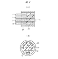
- FIG. 5 is a partially omitted cross-sectional view showing an actuator body with outer cylinders attached to both ends.
- (A) is an expanded sectional view which shows a part of actuator main body
- (B) is a cross-sectional view of (A). It is an expanded sectional view of the A section of FIG. It is a perspective view which shows a part of artificial muscle.
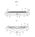
- (A) is a front view which shows the actuator of the expansion
- (B) is a front view which shows the actuator of a contraction state.
- FIG. 5 is a partially omitted cross-sectional view showing an actuator with joint members attached to both ends. It is sectional drawing which shows the modification of the 1st coupling member with which the one end part of an actuator is mounted
- the actuator 10 of the present invention has an actuator body 11 as shown in FIG. As shown in FIGS. 2 to 4, the actuator body 11 is formed by a plurality of artificial muscles 12 arranged in a bundled state.
- each artificial muscle 12 includes an elastic tube 13 having a circular cross-sectional shape, and has a through-hole 14 to which a fluid such as compressed air is supplied.
- the elastic tube 13 can be expanded and contracted in the axial direction and can be expanded and contracted in the radial direction.
- a silicone resin containing silicon as a main component that is, a silicon resin is used.
- the elastic tube 13 may be formed of other synthetic resin, synthetic rubber, or the like.
- a braided tube 15 is provided outside the elastic tube 13.
- the braided tube 15 is a network structure formed by knitting Tetron yarn into a tubular shape, and the outer side of the elastic tube 13 is covered and reinforced by the braided tube 15.
- the material of the braided tube 15 is not limited to Tetron, and various materials such as polyester fibers can be used.
- the elastic tube 13 is exposed to the outside through a gap between yarns constituting the braided tube 15.
- a single layer braided tube 15 is provided outside the elastic tube 13, but the elastic tube 13 may be covered with a plurality of layers of braided tube.
- the first outer cylinder 21 is attached to one end of the actuator body 11, and the second outer cylinder 22 is attached to the other end of the actuator body 11.
- Each outer cylinder 21, 21 is formed of metal or resin.
- An adhesive portion 23 is provided inside the first outer cylindrical body 21, and an adhesive portion 24 is provided inside the second outer cylindrical body 22.
- the adhesive portions 23 and 24 are thermosetting resins, and adhere the elastic tube 13 and the braided tube 15 and fix the artificial muscles 12 to each other.
- the outer cylindrical bodies 21 and 22 and the artificial muscles 12 are bonded to each other. Glue. As shown in FIG.
- the number of artificial muscles 12 constituting the actuator body 11 is arbitrarily set. As shown in FIG. 2B, a plurality of artificial muscles 12 may be bundled so as to be arranged with a gap therebetween, or may be bundled so that the outer peripheral surfaces of the respective artificial muscles 12 are brought into contact with each other. Even if the artificial muscles 12 are bundled so that the outer peripheral surfaces are brought into contact with each other, when the thermosetting resin having fluidity constituting the bonding portions 23 and 24 is injected into the outer cylindrical bodies 21 and 22, the respective artificial muscles The thermosetting resin enters the gap between the 12 braided tubes 15. When the thermosetting resin injected into the outer cylinders 21 and 22 is heat-cured, the bonding portions 23 and 24 are formed, and the adjacent artificial muscles 12 are bonded.
- the depth from the end faces of the bonding portions 23, 24, that is, the axial length D is shorter than the axial length of the outer cylinders 21, 22.
- the bonding portions 23 and 24 may have the same axial length as that of the outer cylindrical bodies 21 and 22.
- thermosetting resin is injected to the outside of the both ends of each artificial muscle 12, and the plurality of artificial muscles 12 and the outer cylinders 21, 22 are fixed by the thermosetting resin. Therefore, the through hole 14 is opened at the end face of the actuator 10 without inserting the sealing member in which the connection hole is formed into the elastic tube 13. Since the sealing member is not inserted into each elastic tube 13, the actuator body 11 can be manufactured using the small-diameter artificial muscle 12, and the actuator 10 can be downsized.
- FIG. 5 (A) is a front view showing the extended actuator 10 attached to the swing arm
- FIG. 5 (B) is a front view showing the contracted actuator 10.
- the swing arm 30 has a first swing member 31 and a second swing member 32. Both swinging members 31 and 32 are connected by a pin 33 and are swingably connected to each other.
- the first bracket 34 is attached to the first swing member 31, and the second bracket 35 is attached to the second swing member 32.
- the first joint member 41 is attached to one end of the actuator body 11, and the second joint member 42 is attached to the other end of the actuator body 11.
- the first joint member 41 is attached to the first bracket 34, and the second joint member 42 is attached to the second bracket 35.
- one end of the actuator body 11 is attached to the first swing member 31 and the other end of the actuator body 11 is attached to the second swing member 32.
- a supply pipe 36 that supplies compressed air that is a fluid is attached to the first joint member 41, and the compressed air supplied by the supply pipe 36 passes through the through holes 14 of all the artificial muscles 12 that constitute the actuator body 11. To be supplied.
- the second joint member 42 the communication between the through hole 14 of the artificial muscle 12 and the outside is blocked by the blocking member. Therefore, as shown in FIG. 5A, the two swinging members 31 and 32 are in a state before being straightly swung under a state in which no fluid is supplied into the artificial muscle 12.
- each artificial muscle 12 expands in the radial direction and contracts in the longitudinal direction.
- the swing arm 30 is bent around the pin 33.
- the actuator 10 is applied to drive the swing arm 30, the swing arm 30 can be driven by supplying and discharging fluid to and from the artificial muscle 12.
- FIG. 6 is a partially omitted cross-sectional view showing an actuator with joint members attached to both ends.
- the first joint member 41 and the second joint member 42 have the same structure and have a cylindrical joint body 43.
- the joint body 43 is made of metal or hard resin.
- a large diameter hole 44 and a small diameter hole 45 are formed in the joint body 43, and a radial abutting surface 46 is provided between the large diameter hole 44 and the small diameter hole 45.
- One end of the actuator body 11 is inserted into the first joint member 41, and the end surface of the first outer cylinder 21 is abutted against the abutting surface 46.
- the other end of the actuator body 11 is inserted into the second joint member 42, and the end surface of the second outer cylinder 22 is abutted against the abutting surface 46.
- a seal member 47 is provided on the abutting surface 46 side of the large diameter hole 44 of each joint body 43.
- a guide ring 48 is provided in the open end of the large-diameter hole 44, and an engaging claw 49 that engages with the joint body 43 is provided in the guide ring 48.
- a lock member 51 is mounted between the guide ring 48 and the seal member 47.
- the lock member 51 is formed of an elastic metal such as stainless steel, and the cylindrical portion 51a fitted into the large-diameter hole 44 and the seal member 47 radially inward from the end of the cylindrical portion 51a on the guide ring 48 side. And a lock claw 51b that is bent toward the front. Therefore, when the end of the actuator body 11 is inserted into the joint body 43, the lock claw 51b is elastically deformed so that the distal end of the lock claw 51b is pushed outward by the outer cylindrical bodies 21 and 22 and extends radially outward. Thus, the insertion operation of the actuator body 11 is allowed.
- the release ring 52 is mounted inside the guide ring 48 so as to be movable in the axial direction.
- the release ring 52 is formed of metal or hard resin, and has a cylindrical portion 53 that is slidably fitted to the guide ring 48.
- a claw actuating portion 53a that contacts the lock claw 51b is provided at one end of the cylindrical portion 53, and an operation portion 53b that protrudes radially outward is provided at the other end.
- An engagement claw 53c that engages with the guide ring 48 is provided on the release ring 52, and the engagement between the engagement claw 53c and the guide ring 48 prevents the release ring 52 from coming off the joint body 43.
- the lock claw 51 b is elastically deformed radially outward, and the lock claw 51 b is separated from the outer cylindrical body 21.
- the actuator body 11 When the actuator body 11 is pulled away from the joint body 43 under this state, the actuator body 11 can be detached from the joint body 43.
- the joint member 41 is a quick joint mechanism 54
- the joint member 42 is also a quick joint mechanism 55. Accordingly, the actuator body 11 can be fastened to the joint body 43 by inserting the end of the actuator body 11 into the joint body 43. Further, the actuator main body 11 can be detached from the joint main body 43 by pushing the release ring 52.
- the distance between the abutting surface 46 and the lock claw 51 b that is, the position where the lock member 51 bites into the outer cylinders 21 and 22 of the actuator body 11 and the axis between the end face of the actuator body 11.
- L be the direction distance.
- the axial length of the bonding portions 23 and 24 from the end face of the actuator body 11 is D.
- the axial length D is set to be longer than the axial distance L (D> L).
- the bonding portion depth of the bonding portions 23, 24, that is, the axial length D is set larger than the distance L of the biting position of the locking member 51, the fastening force of the locking member 51 is applied to the bonding portions 23, 24. Join.
- the end of the actuator body 11 can be securely fastened to the joint body 43 without deforming the end of the actuator body 11.
- the number of artificial muscles 12 constituting the actuator body 11 can be increased without changing the size of the outer cylinders 21 and 22.
- the adhesion part depth of the adhesion parts 23 and 24, that is, the axial length D will be supplemented below.
- the surfaces of the adhesive portions 23 and 24 inside the outer cylindrical bodies 21 and 22 on the opposite side to the end surface of the actuator body 11 may not be finished perpendicular to the axial direction.
- the shortest length with respect to the end surface of the actuator body 11 of the surface that is not finished perpendicular to the axial direction is defined as the bonding portion depth, that is, the axial length D. That is, it is only necessary that the adhesive is filled radially inward with respect to the biting position of the lock member 51.
- the supply pipe 36 communicating with the small diameter hole 45 is connected to the first joint member 41 attached to one end of the actuator body 11.
- the fluid supplied from the fluid supply source 37 by the supply pipe 36 is supplied into the through holes 14 of the respective elastic tubes 13.
- the second joint member 42 attached to the other end portion of the actuator body is provided with a closing member 38 for preventing the fluid from flowing out from the elastic tube 13.
- the second joint member 42 it is possible to use a member in which the small-diameter hole 45 is not provided, but by using a member having the same structure as the first joint member 41, the actuator 10 can be used. The number of parts can be reduced.
- FIG. 7 is a sectional view showing a modification of the first joint member 41 attached to one end of the actuator.
- a small-diameter hole 45 is provided in the central portion in the axial direction.
- a large-diameter hole 44 is provided at one end of the joint body 43a, and a quick joint mechanism 54 is provided in the large-diameter hole 44 in the same manner as the joint body 43 shown in FIG.
- a large diameter hole 44a is provided at the other end of the joint body 43a, and a quick joint mechanism 56 is provided in the large diameter hole 44a.
- the quick joint mechanism 56 has the same structure as that of the quick joint mechanism 54, and members that are the same as the members constituting the quick joint mechanism 54 are given the same reference numerals, and redundant description of the quick joint mechanism 56 is omitted. . With this quick joint mechanism 56, the supply pipe 36 is detachably attached to the joint body 43a.
- the present invention is not limited to the embodiment described above, and various modifications can be made without departing from the scope of the invention.
- the cross-sectional shape of the elastic tube 13 is not limited to a circle, and can be set to a quadrilateral, a polygon, a star, or the like.
- the end surface of the elastic tube 13 on the second outer cylinder 22 side may be sealed with resin without providing the second outer cylinder 22.
- the actuator of the present invention is applied to drive two oscillating members connected by pins.
Landscapes
- Engineering & Computer Science (AREA)
- Chemical & Material Sciences (AREA)
- Analytical Chemistry (AREA)
- Physics & Mathematics (AREA)
- Fluid Mechanics (AREA)
- Mechanical Engineering (AREA)
- General Engineering & Computer Science (AREA)
- Actuator (AREA)
- Manipulator (AREA)
Abstract
アクチュエータ本体(11)は複数本の人工筋肉(12)により形成される。それぞれの人工筋肉(12)は、弾性チューブ(13)とその外側に設けられる組紐チューブ(15)とを備えている。第1の外側筒体(21)がアクチュエータ本体(11)の一端部に装着され、第2の外側筒体(22)がアクチュエータ本体(11)の他端部に装着される。第1の外側筒体(21)と第2の外側筒体(22)の内部に接着部(23,24)が設けられ、接着部(23,24)は弾性チューブ(13)と組紐チューブ(15)とを接着し、第1の外側筒体(21)と人工筋肉(12)とを接着し、第2の外側筒体(22)と人工筋肉(12)とを接着する。
Description
本発明は、弾性チューブを有する複数本の人工筋肉を束ねて形成したアクチュエータに関する。
中空屈曲性のゴム等からなるエンクロージャつまり弾性チューブと、その外側に設けられる管状網状体とを有するロボット用のアクチュエータが、特許文献1に記載されている。このアクチュエータは、例えば、ピン結合された腕部材を揺動するために使用される。また、介護用機器やリハビリ用機器として、複数本の人工筋肉を束ねて組み立てられるアクチュエータが開発されている。
特許文献2には、複数の管状体を束ねた湾曲可能なアクチュエータが記載されている。それぞれの管状部材は、ゴム等からなる中空の弾性伸長体とその外側に囲繞される網組み構造体とにより形成されている。網組み構造体はポリエステル繊維により形成され、それぞれの弾性伸長体の両端部内には封止部材が固定され、封止部材には弾性伸長体の内部に連通する接続孔が設けられている。特許文献3は、ゴムチューブとその外側に被せられる組紐レースとからなる膨張体と、組紐レースよりも短い長さの外周長の組紐レースからなる収縮体とからなる人工筋肉部材を開示している。ゴムチューブとしては、断面円形部材や断面星型のものが使用され、組紐レースは、ポリエステル製の糸が使用される。
特許文献1に記載されるアクチュエータは、弾性チューブとその外側に設けられる管状網状体とからなる1本の人工筋肉により形成されている。このため、腕部材を所定の揺動角度まで揺動させるには、弾性チューブの径方向の膨張収縮量を大きくする必要があり、弾性チューブの耐久性に限度がある。
これに対し、特許文献2に記載されるように、複数の管状体を束ねてアクチュエータを形成すると、各々の管状体の膨張収縮量を大きくすることなく、アクチュエータの軸方向の伸長量を大きくすることができる。しかしながら、特許文献2に記載されるアクチュエータは、各々の管状体の両端部内に封止部材を挿入して固定し、複数の管状部材の両端部が締結ベルトにより結束され、さらに締結ベルトと封止部材とがボルトにより締結されている。このため、小径の管状体を使用することができず、アクチュエータの小型化を達成することができない。
本発明の目的は、アクチュエータの小型化を達成することにある。
本発明のアクチュエータは、弾性チューブと前記弾性チューブの外側に設けられる組紐チューブとを備えた複数本の人工筋肉により形成されるアクチュエータ本体と、前記アクチュエータ本体の端部に装着される外側筒体と、前記外側筒体の内部に設けられ、前記弾性チューブと前記組紐チューブとを接着し、かつ前記外側筒体と前記人工筋肉とを接着する接着部と、を有する。
アクチュエータは複数本の人工筋肉により形成されるアクチュエータ本体の端部に外側筒体が設けられ、外側筒体内に設けられる接着部により外側筒体と人工筋肉とが接着されるようにしたので、流体を供給するための部材を弾性チューブの内部に挿入することなく、弾性チューブ内に直接流体を供給することができる。これにより、小径の人工筋肉によりアクチュエータを構成することができ、アクチュエータを小型化することができる。
以下、本発明の実施の形態を図面に基づいて詳細に説明する。本発明のアクチュエータ10は図1に示されるようにアクチュエータ本体11を有する。アクチュエータ本体11は、図2~図4に示されるように、束ねられた状態となって並列に配置される複数本の人工筋肉12により形成される。
それぞれの人工筋肉12は、図4に示されるように、横断面形状が円形である弾性チューブ13を備え、圧縮空気等の流体が供給される貫通孔14を有している。弾性チューブ13は、軸方向に伸縮自在かつ径方向に膨張収縮自在である。弾性チューブ13としては、高分子シリコーンを主成分とするシリコーン樹脂つまりケイ素樹脂が使用されている。ただし、弾性変形する材料であれば、他の合成樹脂、合成ゴム等により弾性チューブ13を形成するようにしても良い。組紐チューブ15が弾性チューブ13の外側に設けられている。組紐チューブ15はテトロン製の糸を管状に編み上げて形成される網状構造体であり、弾性チューブ13の外側は組紐チューブ15により覆われて補強される。組紐チューブ15の素材としては、テトロン製に限らず、ポリエステル繊維などの種々のものを使用することができる。図4に示されるように、組紐チューブ15を構成する糸の間の隙間を介して、弾性チューブ13は外部に露出される。なお、図4に示すように、弾性チューブ13の外側には1層の組紐チューブ15が設けられているが、複数層の組紐チューブで弾性チューブ13を覆うようにしても良い。
図1に示されるように、第1の外側筒体21がアクチュエータ本体11の一端部に装着され、第2の外側筒体22がアクチュエータ本体11の他端部に装着される。それぞれの外側筒体21,22は金属または樹脂により形成される。第1の外側筒体21の内部には接着部23が設けられ、第2の外側筒体22の内部には接着部24が設けられる。接着部23,24は、熱硬化性の樹脂であり、弾性チューブ13と組紐チューブ15を接着するとともに、人工筋肉12を相互に固定し、それぞれの外側筒体21,22と人工筋肉12とを接着する。図3に示されるように、接着部23を形成する熱硬化性の樹脂を、加熱硬化前の流動状態で外側筒体21と人工筋肉12との間の隙間に注入した後に加熱硬化すると、組紐チューブ15を構成する糸の間の隙間に入り込んで弾性チューブ13と組紐チューブ15とを接着する。接着部24も、同様に、組紐チューブ15を構成する糸の間の隙間に入り込んで弾性チューブ13と組紐チューブ15とを接着する。
アクチュエータ本体11を構成する人工筋肉12の数は、任意に設定される。図2(B)に示されるように、複数本の人工筋肉12を隙間を隔てて配置するように束ねても良く、それぞれの人工筋肉12の外周面を接触させるように束ねても良い。人工筋肉12を外周面を接触させるように束ねても、接着部23,24を構成する流動性を有する熱硬化性樹脂をそれぞれの外側筒体21,22の内部に注入すると、各々の人工筋肉12の組紐チューブ15の隙間内に熱硬化性樹脂が入り込む。外側筒体21,22の内部に注入された熱硬化性樹脂を加熱硬化すると、接着部23,24が形成され、隣り合う人工筋肉12が接着される。接着部23,24の端面からの深さつまり軸方向長さDは、外側筒体21,22の軸方向長さよりも短くなっている。ただし、接着部23,24を外側筒体21,22と同一の軸方向長さとしても良い。
このように、熱硬化性樹脂はそれぞれの人工筋肉12の両端部の外側に注入され、複数の人工筋肉12と外側筒体21,22は熱硬化性樹脂により固定される。従って、接続孔が形成された封止部材を弾性チューブ13の内部に挿入することなく、貫通孔14がアクチュエータ10の端面に開口される。封止部材をそれぞれの弾性チューブ13の内部に挿入することがないので、小径の人工筋肉12を用いてアクチュエータ本体11を製造することができ、アクチュエータ10を小型化することができる。
図5(A)は揺動アームに取り付けられた伸長状態のアクチュエータ10を示す正面図であり、図5(B)は収縮状態のアクチュエータ10を示す正面図である。
揺動アーム30は、第1の揺動部材31と第2の揺動部材32とを有する。両方の揺動部材31,32はピン33により連結され、相互に揺動自在に連結される。第1のブラケット34が第1の揺動部材31に取り付けられ、第2のブラケット35が第2の揺動部材32に取り付けられている。第1の継手部材41がアクチュエータ本体11の一端部に取り付けられ、第2の継手部材42がアクチュエータ本体11の他端部に取り付けられる。第1の継手部材41は第1のブラケット34に装着され、第2の継手部材42は第2のブラケット35に装着される。このように、第1の揺動部材31にアクチュエータ本体11の一端部が装着され、第2の揺動部材32にアクチュエータ本体11の他端部が装着される。
第1の継手部材41には、流体である圧縮空気を供給する供給配管36が装着され、供給配管36により供給される圧縮空気は、アクチュエータ本体11を構成する全ての人工筋肉12の貫通孔14に供給される。これに対し、第2の継手部材42は、閉塞部材により人工筋肉12の貫通孔14と外部との連通が遮断される。したがって、図5(A)に示すように、人工筋肉12内に流体が供給されていない状態のもとでは、2つの揺動部材31,32が真っ直ぐな揺動前の状態となる。外部から供給配管36を介して貫通孔14内に圧縮空気を供給すると、それぞれの人工筋肉12は径方向に膨張するとともに長手方向に収縮する。これにより、図5(B)に示されるように、揺動アーム30はピン33を中心に屈曲される。このように、アクチュエータ10を揺動アーム30の駆動に適用すると、人工筋肉12に対する流体の供給と排出とにより、揺動アーム30を駆動することができる。
図6は両端部に継手部材が装着されたアクチュエータを示す一部省略断面図である。図6に示されるように、第1の継手部材41と第2の継手部材42は、同一構造であり、円筒形状の継手本体43を有する。継手本体43は金属または硬質樹脂により形成される。継手本体43には大径孔44と小径孔45が形成されており、大径孔44と小径孔45の間には径方向の突き当て面46が設けられている。アクチュエータ本体11の一端部は第1の継手部材41に挿入され、第1の外側筒体21の端面が突き当て面46に突き当てられる。アクチュエータ本体11の他端部は第2の継手部材42に挿入され、第2の外側筒体22の端面が突き当て面46に突き当てられる。
外側筒体21,22と大径孔44との間をシールするために、それぞれの継手本体43の大径孔44の突き当て面46側にシール部材47が設けられる。ガイドリング48が大径孔44の開口端部内に設けられ、継手本体43に係合する係合爪49がガイドリング48に設けられている。ロック部材51がガイドリング48とシール部材47の間に装着される。
ロック部材51は、ステンレス等の弾性を有する金属により形成され、大径孔44に嵌合する円筒部51aと、この円筒部51aのガイドリング48側の端部から径方向内方にシール部材47に向けて折り曲げられるロック爪51bとを有している。したがって、アクチュエータ本体11の端部をそれぞれの継手本体43内に挿入するときには、ロック爪51bの先端が外側筒体21,22に押されて径方向外方に広がるようにロック爪51bが弾性変形してアクチュエータ本体11の挿入動作を許容する。これに対し、アクチュエータ本体11を継手本体43から外すように引っ張ると、ロック爪51bが外側筒体21,22に押し付けられてロック爪51bの自緊作用によりアクチュエータ本体11の抜けが防止される。
解放リング52がガイドリング48の内側に軸方向に移動自在に装着されている。解放リング52は、金属または硬質樹脂により形成され、ガイドリング48に摺動自在に嵌合する円筒部53を有している。ロック爪51bに当接する爪作動部53aが円筒部53の一端部に設けられ、他端部には径方向外方に突出する操作部53bが設けられている。ガイドリング48に係合する係合爪53cが解放リング52に設けられ、係合爪53cとガイドリング48との係合により解放リング52の継手本体43からの抜けが防止される。解放リング52を図6に示す位置よりもロック部材51に向けて押し込むと、ロック爪51bが径方向外方に弾性変形して、ロック爪51bは外側筒体21から離れた状態となる。この状態のもとでアクチュエータ本体11を継手本体43から離すように引っ張ると、アクチュエータ本体11を継手本体43から取り外すことができる。このように、継手部材41はクイック継手機構54となっており、同様に継手部材42もクイック継手機構55となっている。これにより、アクチュエータ本体11の端部を継手本体43に挿入することによりアクチュエータ本体11を継手本体43に締結することができる。また、解放リング52を押し込むことによりアクチュエータ本体11を継手本体43から取り外すことができる。
図6に示されるように、突き当て面46とロック爪51bとの間の距離、つまりロック部材51がアクチュエータ本体11の外側筒体21,22に食い込む位置と、アクチュエータ本体11の端面との軸方向距離をLとする。また、アクチュエータ本体11の端面からの、接着部23,24の軸方向長さをDとする。軸方向長さDは軸方向の距離Lよりも長く設定されている(D>L)。このように、接着部23,24の接着部深さ、つまり軸方向長さDをロック部材51の食い込み位置の距離Lよりも大きく設定すると、ロック部材51の締結力は接着部23,24に加わる。これにより、外側筒体21,22を薄くしてもアクチュエータ本体11の端部を変形させることなく、確実にアクチュエータ本体11の端部を継手本体43に締結することができる。その結果、外側筒体21、22の大きさを変えずにアクチュエータ本体11を構成する人工筋肉12の数を増やすことができる。
接着部23,24の接着部深さ、つまり軸方向長さDについては、以下に補足する。アクチュエータ本体11の端面に対して反対側の、外側筒体21,22内部の接着部23,24の面は、軸方向に対して垂直に仕上がらないことがある。その場合には、軸方向に対して垂直に仕上がらない面の、アクチュエータ本体11の端面に対して最短の長さを接着部深さ、つまり軸方向長さDとする。つまり、ロック部材51の食い込み位置に対して半径方向内側に、接着剤が満たされていればよい。
アクチュエータ本体11の一端部に装着される第1の継手部材41には、小径孔45に連通する供給配管36が接続される。供給配管36により流体供給源37から供給される流体がそれぞれの弾性チューブ13の貫通孔14内に供給される。一方、アクチュエータ本体の他端部に装着される第2の継手部材42には、弾性チューブ13内からの流体の流出を防止するための閉塞部材38が設けられている。第2の継手部材42としては、小径孔45が設けられていない形態のものを使用することも可能であるが、第1の継手部材41と同一の構造のものを使用することにより、アクチュエータ10の部品点数を低減することができる。
図7はアクチュエータの一端部に装着される第1の継手部材41の変形例を示す断面図である。この継手部材41の継手本体43aにおいては、軸方向の中央部に小径孔45が設けられている。継手本体43aの一端部には大径孔44が設けられ、大径孔44内には図6に示した継手本体43と同様にクイック継手機構54が設けられている。継手本体43aの他端部には大径孔44aが設けられ、大径孔44a内にはクイック継手機構56が設けられる。クイック継手機構56はクイック継手機構54と同様の構造であり、クイック継手機構54を構成する部材と共通する部材には同一の符号を付して、クイック継手機構56についての重複した説明を省略する。このクイック継手機構56により、供給配管36が継手本体43aに取り外し自在に装着される。
本発明は前記実施の形態に限定されるものではなく、その要旨を逸脱しない範囲で種々変更可能である。例えば、弾性チューブ13の断面形状は、円形に限られず、四辺形、多角形、星型等に設定することができる。また、第2の外側筒体22を設けることなく、第2の外側筒体22側の弾性チューブ13の端面を、樹脂で封止してもよい。
本発明のアクチュエータは、ピンにより連結される2つの揺動部材を駆動するために適用される。
Claims (8)
- 弾性チューブと前記弾性チューブの外側に設けられる組紐チューブとを備えた複数本の人工筋肉により形成されるアクチュエータ本体と、
前記アクチュエータ本体の端部に装着される外側筒体と、
前記外側筒体の内部に設けられ、前記弾性チューブと前記組紐チューブとを接着し、かつ前記外側筒体と前記人工筋肉とを接着する接着部と、
を有するアクチュエータ。 - 請求項1記載のアクチュエータにおいて、前記外側筒体が挿入される継手部材を有するアクチュエータ。
- 請求項2記載のアクチュエータにおいて、前記外側筒体と前記継手部材とを締結するロック部材を前記継手部材に設けた、アクチュエータ。
- 請求項3記載のアクチュエータにおいて、前記アクチュエータ本体の端面からの前記接着部の軸方向長さは、前記ロック部材が前記外側筒体に食い込む位置と前記アクチュエータ本体の端面との軸方向距離よりも長い、アクチュエータ。
- 弾性チューブと前記弾性チューブの外側に設けられる組紐チューブとを備えた複数本の人工筋肉により形成されるアクチュエータ本体と、
前記アクチュエータ本体の一端部に装着される第1の外側筒体と、
前記アクチュエータ本体の他端部に装着される第2の外側筒体と、
前記第1と第2の外側筒体の内部に設けられ、前記弾性チューブと前記組紐チューブとを接着し、かつ前記第1と第2の外側筒体と前記人工筋肉とを接着する接着部と、
を有するアクチュエータ。 - 請求項5記載のアクチュエータにおいて、前記第1の外側筒体が挿入される第1の継手部材と、前記第2の外側筒体が挿入される第2の継手部材とを有するアクチュエータ。
- 請求項6記載のアクチュエータにおいて、前記第1の外側筒体と前記第1の継手部材とを締結するロック部材を前記第1の継手部材に設け、前記第2の外側筒体と前記第2の継手部材とを締結するロック部材を前記第2の継手部材に設けた、アクチュエータ。
- 請求項7記載のアクチュエータにおいて、前記アクチュエータ本体の端面からの前記接着部の軸方向長さは、前記ロック部材が前記外側筒体に食い込む位置と前記アクチュエータ本体の端面との軸方向距離よりも長い、アクチュエータ。
Priority Applications (2)
| Application Number | Priority Date | Filing Date | Title |
|---|---|---|---|
| US15/549,481 US10415606B2 (en) | 2015-02-20 | 2015-10-28 | Actuator |
| DE112015006193.2T DE112015006193B4 (de) | 2015-02-20 | 2015-10-28 | Aktuator |
Applications Claiming Priority (2)
| Application Number | Priority Date | Filing Date | Title |
|---|---|---|---|
| JP2015031459A JP6292580B2 (ja) | 2015-02-20 | 2015-02-20 | アクチュエータ |
| JP2015-031459 | 2015-02-20 |
Publications (1)
| Publication Number | Publication Date |
|---|---|
| WO2016132608A1 true WO2016132608A1 (ja) | 2016-08-25 |
Family
ID=56692142
Family Applications (1)
| Application Number | Title | Priority Date | Filing Date |
|---|---|---|---|
| PCT/JP2015/080388 Ceased WO2016132608A1 (ja) | 2015-02-20 | 2015-10-28 | アクチュエータ |
Country Status (4)
| Country | Link |
|---|---|
| US (1) | US10415606B2 (ja) |
| JP (1) | JP6292580B2 (ja) |
| DE (1) | DE112015006193B4 (ja) |
| WO (1) | WO2016132608A1 (ja) |
Families Citing this family (7)
| Publication number | Priority date | Publication date | Assignee | Title |
|---|---|---|---|---|
| JP7109893B2 (ja) * | 2017-09-11 | 2022-08-01 | 株式会社コガネイ | アクチュエータ |
| JP7120615B2 (ja) * | 2017-11-17 | 2022-08-17 | Nke株式会社 | 動作補助具及び固定方法 |
| JP7169609B2 (ja) * | 2018-11-02 | 2022-11-11 | Nke株式会社 | 人工筋肉、人工筋肉セット及び動作補助具 |
| JP7153325B2 (ja) * | 2018-11-02 | 2022-10-14 | Nke株式会社 | 人工筋肉、人工筋肉セット及び動作補助具並びに人工筋肉セットの製造方法 |
| CN110282032B (zh) * | 2019-07-29 | 2024-10-01 | 江苏徐工工程机械研究院有限公司 | 驾驶室举升系统和车辆 |
| JP7120987B2 (ja) * | 2019-12-23 | 2022-08-17 | 株式会社コガネイ | アクチュエータ |
| WO2025035028A1 (en) * | 2023-08-08 | 2025-02-13 | Adaract | Muscle actuator system |
Citations (2)
| Publication number | Priority date | Publication date | Assignee | Title |
|---|---|---|---|---|
| JP2010221329A (ja) * | 2009-03-23 | 2010-10-07 | Olympus Corp | 駆動機構 |
| JP2010279689A (ja) * | 2009-05-07 | 2010-12-16 | Hisao Ishimura | 圧縮気体を使った人工筋肉 |
Family Cites Families (6)
| Publication number | Priority date | Publication date | Assignee | Title |
|---|---|---|---|---|
| CA1228096A (en) | 1983-11-21 | 1987-10-13 | Mirko Kukolj | Axially contractable actuator |
| JP2846346B2 (ja) | 1989-06-23 | 1999-01-13 | 株式会社ブリヂストン | 湾曲可能なアクチュエータ |
| JPH0348004A (ja) * | 1989-07-11 | 1991-03-01 | Bridgestone Corp | 複動型アクチュエータ |
| DE10015411C1 (de) * | 2000-03-28 | 2001-07-26 | Kuka Roboter Gmbh | Vorrichtung zum Gewichtsausgleich an einem Roboter |
| US6868773B2 (en) * | 2002-08-13 | 2005-03-22 | Electro Cam Corporation | Fluidic actuator |
| US9463085B1 (en) * | 2013-02-20 | 2016-10-11 | Daniel Theobald | Actuator with variable attachment connector |
-
2015
- 2015-02-20 JP JP2015031459A patent/JP6292580B2/ja active Active
- 2015-10-28 DE DE112015006193.2T patent/DE112015006193B4/de active Active
- 2015-10-28 WO PCT/JP2015/080388 patent/WO2016132608A1/ja not_active Ceased
- 2015-10-28 US US15/549,481 patent/US10415606B2/en active Active
Patent Citations (2)
| Publication number | Priority date | Publication date | Assignee | Title |
|---|---|---|---|---|
| JP2010221329A (ja) * | 2009-03-23 | 2010-10-07 | Olympus Corp | 駆動機構 |
| JP2010279689A (ja) * | 2009-05-07 | 2010-12-16 | Hisao Ishimura | 圧縮気体を使った人工筋肉 |
Also Published As
| Publication number | Publication date |
|---|---|
| US20180031009A1 (en) | 2018-02-01 |
| DE112015006193T5 (de) | 2017-11-09 |
| JP2016153663A (ja) | 2016-08-25 |
| DE112015006193B4 (de) | 2025-01-02 |
| US10415606B2 (en) | 2019-09-17 |
| JP6292580B2 (ja) | 2018-03-14 |
Similar Documents
| Publication | Publication Date | Title |
|---|---|---|
| JP6292580B2 (ja) | アクチュエータ | |
| US7086322B2 (en) | Fluidic device | |
| US20170363230A1 (en) | Hose arrangements | |
| JP2018035930A (ja) | 流体圧アクチュエータ | |
| JP7109893B2 (ja) | アクチュエータ | |
| JP5415801B2 (ja) | ホース継手 | |
| US20020108491A1 (en) | Tension actuator having constraining sleeve immersed in a single layer of elastomeric material | |
| JP7120987B2 (ja) | アクチュエータ | |
| JP7301418B2 (ja) | 自走式ロボット | |
| JP2017009099A (ja) | 流路閉塞用のバッグ | |
| JP2019120373A (ja) | アクチュエータ | |
| JP2008126041A (ja) | 人形、おもちゃのロボットなどの構成部材 | |
| CN104565596A (zh) | 柔性软管 | |
| JP6585946B2 (ja) | 流体圧アクチュエータ | |
| JP7736554B2 (ja) | 流体圧アクチュエータ | |
| JP6354052B2 (ja) | 複合流体圧アクチュエータ | |
| US367790A (en) | Charles daeeah | |
| JP6675972B2 (ja) | 流体継手および流体圧アクチュエータ | |
| JP5726465B2 (ja) | 連結具 | |
| JP7698764B1 (ja) | 流体圧アクチュエータ | |
| JP2017020608A (ja) | 流体圧アクチュエータ | |
| JP6873468B2 (ja) | アクチュエータ | |
| JP2020197265A (ja) | チューブ固定具およびアクチュエータ | |
| JP2014190366A (ja) | 管継手 | |
| WO2020129743A1 (ja) | 流体圧アクチュエータ |
Legal Events
| Date | Code | Title | Description |
|---|---|---|---|
| 121 | Ep: the epo has been informed by wipo that ep was designated in this application |
Ref document number: 15882709 Country of ref document: EP Kind code of ref document: A1 |
|
| WWE | Wipo information: entry into national phase |
Ref document number: 112015006193 Country of ref document: DE |
|
| 122 | Ep: pct application non-entry in european phase |
Ref document number: 15882709 Country of ref document: EP Kind code of ref document: A1 |