WO2016132477A1 - 工作機械 - Google Patents
工作機械 Download PDFInfo
- Publication number
- WO2016132477A1 WO2016132477A1 PCT/JP2015/054430 JP2015054430W WO2016132477A1 WO 2016132477 A1 WO2016132477 A1 WO 2016132477A1 JP 2015054430 W JP2015054430 W JP 2015054430W WO 2016132477 A1 WO2016132477 A1 WO 2016132477A1
- Authority
- WO
- WIPO (PCT)
- Prior art keywords
- base
- processing module
- wiring
- machine tool
- module
- Prior art date
- Legal status (The legal status is an assumption and is not a legal conclusion. Google has not performed a legal analysis and makes no representation as to the accuracy of the status listed.)
- Ceased
Links
Images



Classifications
-
- B—PERFORMING OPERATIONS; TRANSPORTING
- B23—MACHINE TOOLS; METAL-WORKING NOT OTHERWISE PROVIDED FOR
- B23Q—DETAILS, COMPONENTS, OR ACCESSORIES FOR MACHINE TOOLS, e.g. ARRANGEMENTS FOR COPYING OR CONTROLLING; MACHINE TOOLS IN GENERAL CHARACTERISED BY THE CONSTRUCTION OF PARTICULAR DETAILS OR COMPONENTS; COMBINATIONS OR ASSOCIATIONS OF METAL-WORKING MACHINES, NOT DIRECTED TO A PARTICULAR RESULT
- B23Q1/00—Members which are comprised in the general build-up of a form of machine, particularly relatively large fixed members
Definitions
- the present invention relates to a machine tool in which a machining module is movable on a base, and the wiring state of the wiring changes following the movement of the machining module.
- Patent Document 1 describes a case where a maintenance module is pulled out from a production module (machine body portion of a machine tool) in a production line.
- a production module machine body portion of a machine tool
- a processing module is mounted on each base so as to be movable in the front-rear direction.
- the machining module is pulled out forward by moving a rail on the base, and can be transferred to a maintenance table arranged in front of the base.
- each cable connection terminal of a base and a processing module is connected via an extension cable so that a trial run, adjustment, etc. can be performed with respect to the processing module of a maintenance stand.
- an object of the present invention is to provide a machine tool in which a machining module can be moved on a base while wiring is connected in order to solve such a problem.
- a machine tool includes a base and a machining module that can move in the front-rear direction on the base, and wiring for driving the machining module is drawn from the base side to the machining module.
- the wiring is forwarded from the rear part of the base, forwarded through the folded part and connected to the rear part of the machining module, and when the machining module is moved.
- the folded portion is always routed so as to be positioned in front of the connecting portion with the processing module.
- the wiring connected to the machining module is sent forward from the rear part of the base and returned to the rear through the folded part, and the folded part is always forward of the connected part with the machining module. Since the wiring module is routed so as to be positioned at the position, the routing state of the wiring can be changed following the processing module moving on the base, and the processing module can be moved on the base while the wiring is connected. .
- FIG. 3 It is the perspective view which showed the processing machine line comprised by the machine tool of embodiment. It is the perspective view which showed one Embodiment of the processing module. It is the perspective view which showed the state which the machine tool and the base isolate
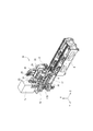
- FIG. 1 is a perspective view showing a processing machine line constituted by the machine tool of the present embodiment.
- this processing machine line 1
- six machine tools 5 mounted on a base 2 are arranged.
- the six machine tools 5 are all the same type of NC lathe and have the same internal structure and overall shape and dimensions.
- the machine tool 5 is a compact machine body designed to have a small width dimension, and the entire processing machine line 1 in which the machine tools 5 are arranged close to each other is also compactly assembled.
- FIG. 2 is a perspective view showing the processing module. Although two machine tools 5 can be mounted on the base 2, only one machining module 10 is shown in the drawing.
- the processing module 10 is a turret lathe provided with a turret holding a rotary tool such as an end mill or a drill or a cutting tool such as a cutting tool. Therefore, the machining module 10 includes a headstock 12 having a chuck 11 for gripping a workpiece (workpiece), a turret device 13 to which a tool is attached, and a Z-axis drive that moves the turret device 13 along the Z-axis and the X-axis.
- An apparatus, an X-axis drive device, and a machining control device 15 for controlling each drive unit are provided.
- the Z-axis is a horizontal axis parallel to the rotation axis (main axis) of the headstock 12, and in this embodiment is the front-rear direction of the machine tool 5 (processing module 10).
- the X axis is orthogonal to the Z axis, and is a moving axis that moves the tool of the turret device 13 forward and backward with respect to the Z axis, and is a vertical direction in this embodiment.
- the Y axis is the width direction of the processing module 10 that is orthogonal to the Z axis and the X axis.
- the machining module 10 includes a movable bed 16 having wheels so that the processing module 10 can move in the Z-axis direction, which is the front-rear direction, on the base 2, and the headstock 12 is fixed on the movable bed 16.
- the spindle stock 12 is configured such that the chuck 11 and the spindle-side pulley are integrated with a spindle that is rotatably supported, and the spindle servomotor 18 is rotated.
- the turret device 13 is mounted on a Z-axis slider 22, and the Z-axis slider 22 is further mounted on an X-axis slider 26.
- the Z-axis slider 22 is configured to be movable in the horizontal direction parallel to the Z-axis by sliding in the base 21 fixed to the X-axis slider 26.
- the Z-axis drive device employs a ball screw mechanism that converts the rotational output of the Z-axis servomotor 23 into a straight-ahead motion in order to move the Z-axis slider 22 in the Z-axis direction.
- the screw shaft is rotated by driving the Z-axis servomotor 23, the rotational motion is converted into the linear motion of the ball nut, and the Z-axis slider 22 is moved in a direction parallel to the Z-axis.
- a column 25 having two guides 27 is erected and fixed to the movable bed 16, and an X-axis slider 26 is slidably attached to the guides 27.
- the X-axis slider 26 can be moved up and down along the guide 27, and this X-axis drive device also employs a ball screw mechanism to convert the rotation output of the X-axis servomotor 28 into the up-and-down movement of the X-axis slider 26.
- the screw shaft is rotated by driving the X-axis servomotor 28, and the rotational motion is converted into the linear motion of the ball nut, so that the X-axis slider 26 can be moved up and down.
- the processing module 10 can move in the front-rear direction (Z-axis direction) when the movable bed 16 moves on the base 2. For example, when the tool module is pulled forward, the tool is changed or the setup is changed in accordance with the work change. When the tool module is pulled rearward, it is placed on the carriage 170 as shown and the machining module 10 is replaced. It becomes possible to do. Thus, since the processing module 10 can be pulled out with respect to the base 2, even if the machine tools 5 are arranged close to each other, operations such as maintenance, changeover and replacement of each machine tool 5 are easily performed. It is possible.
- FIG. 3 is a perspective view showing a state where the machine tool 5 and the base 2 are separated.
- the machine tool 5 in the drawing is in a state in which a part of the outer cover 3 is removed, and only one machine tool 5 is shown for the base 2 on which two machine tools 5 can be mounted.
- FIG. 3 shows a control panel 6 for supplying power to the processing module 10 and communicating with a work transfer device of the processing machine line 1.
- the workpiece transfer device performs workpiece transfer with each machine tool 5 shown in FIG. 1, and is arranged in a front cover 4 formed in front of the machine tool 5.
- a space communicated in the width direction is formed by the front cover 4 of each machine tool 5, and a work transfer device including a robot arm is installed in the space so as to be able to travel.
- a control panel 6 is arranged for each base 2 on which two machine tools 5 can be mounted.
- the control panel 6 is mounted on a traveling table 31 with casters and is disposed on the back of the processing machine line 1 behind the base 2 and the machine tool 5.
- a wiring 32 for driving the machining module 10 extends from the control panel 6.
- the wiring 32 is, for example, a power cable for driving the main shaft servomotor 18, the Z-axis servomotor 23, and the X-axis servomotor 28, or a communication cable for exchanging signals for controlling the drive.
- the chuck 11 and the turret device 13 of the main shaft 12 have a drive portion that is operated by hydraulic oil or compressed air. Therefore, a hydraulic unit (not shown) and an air compressor are installed on the back of the processing machine line 1. Therefore, the wiring 32 includes a hydraulic hose 323 and an air hose 322 for supplying such hydraulic oil and compressed air (see FIG. 5).
- FIG. 4 is a side view of the machine tool 5 and particularly shows a state in which the wiring 32 is routed.
- the wiring 32 is fed forward (left side in the drawing) from the rear portion of the base 2, and a U-shaped folded portion 36 is formed in front of the forward feed portion 35.
- the wiring 32 has a rear feed portion 37 that is sent in a direction returning from the folded portion 36 to the rear.
- the rear feed portion 37 extends to the rear portion of the machining module 10, and the rising portion 38 lifted upward is connected to the lower portion of the machining control device 15.
- the lower front feed portion 35 and the upper rear feed portion 37 are aligned so as to overlap each other when viewed in the vertical direction.
- the connector 39 is provided at the leading end of the power cable and the communication cable in the wiring 32 and is attachable to and detachable from the connector on the processing control device 15 side.
- the air hose 322 and the hydraulic hose 323 in the wiring 32 are provided with couplers 326 and 327 at the tip of the rising portion, and are connected to the machining module side coupler located under the machining control device 15.
- the routed wiring 32 is housed in the base 2 such that the forward feed portion 35, the folded portion 36, and the backward feed portion 37 are positioned below the processing module 10. This is to prevent the processing module 10 moving in the front-rear direction from being caught. Accordingly, only the rising portion 38 enters the processing module 10 side of the wiring 32.
- the wiring 32 is configured so that its routing state changes as the machine tool 5 (processing module 10) moves in the front-rear direction. That is, the position of the folded portion 36 moves back and forth, and the lengths of the front feed portion 35 and the rear feed portion 37 change accordingly. At that time, the folded-back portion 36 is always located in front of the connection portion with the processing module 10, and its shape is substantially constant.
- the tip position of the folded portion 36 is designed to move forward by a distance A (350 mm) and rearward by a distance B (250 mm). Therefore, the machine tool 5 can move forward by 700 mm and backward by 500 mm.
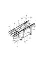
- FIG. 5 is a view showing the guide, and is an enlarged view of FIG. 3 showing the rear feed portion 37 and the rising portion 38 from the folded portion 36 of the wiring 32.
- the wiring 32 includes a cable 321 in which a power cable and a communication cable are bundled with respect to one machine tool 5, an air hose 322 for supplying and exhausting compressed air, and a hydraulic hose 323 for supplying and discharging hydraulic oil. Is provided.
- the cable 321 and the two air hoses 322 form a set of wires 32, and the three hydraulic hoses 323 are routed as another set of wires 32.
- the rear feed portion 37 is positioned by the two upper cover members 41 arranged on the left and right of each set of wires 32.
- the upper cover member 41 is formed of a thin plate and has a groove shape having an upper surface 411 and left and right side surfaces 412, and the upper surface 411 is upward at the rear end corresponding to the rising portion 38 of the wiring 32.
- a bent guide portion 413 is formed.
- the upper cover member 41 is fixed to the bottom surface portion of the movable bed 16 constituting the processing module 10.
- the wiring 32 has a rear feed portion 37 surrounded by the upper cover member 41 on the upper side and the left and right sides, and a plurality of cables 321, air hoses 322, or a plurality of hydraulic hoses 323 are positioned together. .
- the forward feed portion 35 of the wiring 32 does not interfere with the movement of the machine tool 5 (processing module 10), there is no need to provide a cover member at that point.
- the routing state of the wiring 32 needs to change without resistance so as not to hinder the smooth movement of the processing module 10.
- the plurality of wirings 32 are always in a collective state and have a straight posture in the front-rear direction. Therefore, in the present embodiment, the lower cover member 42 is disposed at a position indicated by a broken line in FIG.
- the lower cover member 42 has the same shape as the upper cover member 41 and is fixed to the base 2 by being inverted upside down.
- the wiring 32 is supported such that the forward feed portion 35 is surrounded by the lower cover member 42 on the lower side and the left and right sides, and a plurality of cables 321 and air hoses 322 or a plurality of hydraulic hoses 323 are respectively positioned together. Has been.
- the wiring 32 is routed from the rear portion of the base 2 with the front feed portion 35, the turn-back portion 36, and the rear feed portion 37, so that the processing module 10 can be connected even when the wiring 32 is connected.
- the base 2 can be moved in the front-rear direction.
- the machining module 10 moves, the lengths of the forward feed portion 35 and the backward feed portion 37 change, and the folded portion 36 is always located in front of the connection portion with the machining module 10 and its shape is substantially constant. is there. Therefore, since the wiring state of the wiring 32 changes following the movement of the machining module 10 without difficulty, the machining module 10 can be moved smoothly.
- the wiring 32 is routed below the moving processing module 10, it does not interfere with the processing module 10.
- the upper cover member 41 is attached to the bottom surface of the movable bed 16 and is positioned so that the wiring 32 is covered from above by the upper cover member 41, the wiring 32 prevents the movement of the processing module 10. There is nothing wrong. Further, since the wiring 32 is positioned by the upper cover member 41, its routing state changes without following the movement of the machine tool 5 without difficulty. Such an effect can be obtained more effectively by positioning the forward feed portion 35 of the wiring 32 so as to be supported by the lower cover member 42.
- connection positions of the connector 39 of the cable 321, the air hose 322, and the couplers 326 and 327 of the hydraulic hose 323 are gathered at the rear portion of the processing module 10, particularly the same location under the processing control device 15. It is possible to easily attach and detach when 10 is pulled backward from the base 2.
- the machine tool 5 and the machining module 10 of the above embodiment are merely examples, and any machine tool that can move the machining module in the front-rear direction with respect to the base is applicable.
- the said embodiment demonstrated the structure which provided the upper cover member 41 and the lower cover member 42, if the change of the routing state of the wiring 32 accompanying the movement of the process module 10 is not prevented, for example, the some wiring 32 is provided. May be bundled with a string member at a plurality of locations and tied to the movable bed 16 or the base 2.
Landscapes
- Engineering & Computer Science (AREA)
- Mechanical Engineering (AREA)
- Machine Tool Units (AREA)
- Auxiliary Devices For Machine Tools (AREA)
Abstract
ベース(2)と、そのベース(2)上を前後方向に移動可能な加工モジュール(10)とを有し、加工モジュール(10)を駆動させるための配線(32)がベース(2)側から加工モジュール(10)へと引き回されたものであって、配線(32)は、ベース(2)の後方部分から前方に送られ、折返し部分(36)を介して後方へと送られて加工モジュール(10)の後部に接続され、加工モジュール(10)の移動の際、折返し部分(36)が常に加工モジュール(10)との接続部分より前方に位置するように引き回されたものである。
Description
本発明は、加工モジュールがベース上を移動可能な工作機械であって、その加工モジュールの移動に追随して配線の引き回し状態が変化するようにした工作機械に関する。
下記特許文献1には、生産ライン内の加工モジュール(工作機械の機械本体部)を引き出してメンテナンス作業を行う場合について記載がある。その生産ラインは、複数のベースが隣り合って並べられ、ベース毎に加工モジュールが前後方向に移動可能に搭載されている。その加工モジュールは、ベース上のレールを移動して前方に引き出され、ベース前方に配置されたメンテナンス台に移し替えることが可能になっている。そして、メンテナンス台の加工モジュールに対して試運転や調整などができるように、ベースと加工モジュールとの各ケーブル接続端子同士が延長ケーブルを介して接続される。
しかし、加工モジュールをベースから前方へ引き出した場合に、延長ケーブルを使用しなければメンテナンスが行えないのでは非常に不便であり、加工モジュールをベースに対して移動可能して作業性を向上させた効果を損なわせてしまっている。また、使用しない延長ケーブルは、普段保管しておかなければならない点でも不便である。
そこで、本発明は、かかる課題を解決すべく、配線を接続させたままベース上を加工モジュールが移動可能な工作機械を提供することを目的とする。
本発明の一態様における工作機械は、ベースと、そのベース上を前後方向に移動可能な加工モジュールとを有し、前記加工モジュールを駆動させるための配線が前記ベース側から前記加工モジュールへと引き回されたものであって、前記配線は、前記ベースの後方部分から前方に送られ、折返し部分を介して後方へと送られて前記加工モジュールの後部に接続され、前記加工モジュールの移動の際、前記折返し部分が常に前記加工モジュールとの接続部分より前方に位置するように引き回されたものである。
本発明によれば、加工モジュールに接続した配線が、ベースの後方部分から前方へと送られ、折返し部分を介して後方へと戻るようにし、その折返し部分が常に加工モジュールとの接続部分より前方に位置するように引き回されているため、ベース上を移動する加工モジュールに追随して配線の引き回し状態を変化させることができ、配線を接続させたままでベース上を加工モジュールが移動可能である。
次に、本発明に係る工作機械の一実施形態について図面を参照しながら以下に説明する。図1は、本実施形態の工作機械によって構成された加工機械ラインを示した斜視図である。この加工機械ライン1は、ベース2上に搭載された工作機械5が6台並んでいる。6台の工作機械5はいずれも同じ型のNC旋盤であり、内部構造および全体の形状や寸法が同じものである。工作機械5は、幅寸法が小さく設計されたコンパクトな機体であり、その工作機械5同士が近接して配置された加工機械ライン1も全体がコンパクトにまとまっている。
工作機械5は、全体が外装カバー3によって覆われており、その内部には工作機械本体を構成する加工モジュールが設けられている。図2は、その加工モジュールを示した斜視図である。ベース2には2台の工作機械5が搭載可能であるが、図面では1台分の加工モジュール10のみが示されている。加工モジュール10は、エンドミルやドリルなどの回転工具、或いはバイトなどの切削工具を保持したタレットを備えるタレット旋盤である。そのため加工モジュール10は、工作物(ワーク)を把持するチャック11を備えた主軸台12、工具が取り付けられたタレット装置13、そのタレット装置13をZ軸やX軸に沿って移動させるZ軸駆動装置やX軸駆動装置、そして各駆動部を制御するための加工制御装置15などを備えている。
ここで、Z軸は、主軸台12の回転軸(主軸)と平行な水平軸であり、本実施形態では工作機械5(加工モジュール10)の前後方向である。また、X軸は、Z軸に対して直交し、タレット装置13の工具をZ軸に対して進退させる移動軸であり、本実施形態では垂直方向である。そして、Y軸は、Z軸及びX軸に直行する加工モジュール10の幅方向である。
加工モジュール10は、ベース2の上を前後方向であるZ軸方向に移動できるように車輪を備えた可動ベッド16を備え、その可動ベッド16上に主軸台12が固定されている。主軸台12は、回転自在に支持された主軸にチャック11と主軸側プーリとが一体になり、主軸用サーボモータ18の回転が与えられるよう構成されている。一方、タレット装置13は、Z軸スライダ22に搭載され、更にそのZ軸スライダ22がX軸スライダ26に搭載されている。
Z軸スライダ22は、X軸スライダ26に固定されたベース21内を摺動することにより、Z軸に平行な水平方向に移動自在な構成となっている。Z軸駆動装置には、Z軸スライダ22をZ軸方向に移動させるため、Z軸用サーボモータ23の回転出力を直進運動に変換するボールネジ機構が採用されている。すなわち、Z軸用サーボモータ23の駆動によりネジ軸が回転し、その回転運動がボールナットの直線運動に変換され、Z軸スライダ22がZ軸と平行な方向に移動するよう構成されている。
可動ベッド16には2本のガイド27を備えたコラム25が起立して固定され、そのガイド27に対してX軸スライダ26が摺動自在に取り付けられている。X軸スライダ26は、ガイド27に沿った昇降が可能であり、このX軸駆動装置にもX軸用サーボモータ28の回転出力をX軸スライダ26の昇降運動に変換するため、ボールネジ機構が採用されている。よって、X軸用サーボモータ28の駆動によりネジ軸が回転し、その回転運動がボールナットの直線運動に変換され、X軸スライダ26の昇降が可能になる。
加工モジュール10は、可動ベッド16がベース2上を移動することにより前後方向(Z軸方向)への移動が可能である。例えば、前方へ引き出された場合には工具の交換やワーク変更に伴う段取り換え等が行われ、後方側へ引き出された場合には、図示するように台車170に載せて加工モジュール10そのものの交換することが可能になる。このように加工モジュール10がベース2に対して引き出し可能であるため、工作機械5同士が近接して配置されていたとしても各工作機械5のメンテナンス、段取り換え、交換等の作業を簡単に行うことが可能である。
ここで、図3は、工作機械5とベース2との分離した状態を示した斜視図である。図面の工作機械5は、外装カバー3の一部が取り外された状態であり、2台の工作機械5が搭載可能なベース2に対して1台のみを示している。さらに、図3には、加工モジュール10への電源供給や加工機械ライン1のワーク搬送装置との通信を行うための制御盤6が示されている。ワーク搬送装置は、図1に示す各工作機械5との間でワークの受渡しを行うものであり、工作機械5の前方に形成された前カバー4内に配置さている。加工機械ライン1では、各工作機械5の前カバー4によって幅方向に連通した一つの空間が形成され、その中にロボットアームを備えたワーク搬送装置が走行可能に設置されている。
加工機械ライン1では、2台の工作機械5を搭載可能なベース2毎に制御盤6が配置されている。その制御盤6は、キャスタ付きの走行テーブル31に搭載され、ベース2及び工作機械5の後方である加工機械ライン1の背部に配置される。そして、その制御盤6からは加工モジュール10を駆動させるための配線32が延びている。配線32は、例えば主軸用サーボモータ18、Z軸用サーボモータ23およびX軸用サーボモータ28を駆動させるための電源ケーブルや、その駆動制御を行うための信号をやり取りする通信ケーブルなどである。また、主軸12のチャック11やタレット装置13などは、作動油や圧縮エアによって作動する駆動部分を有している。そのため、加工機械ライン1の背部には不図示の油圧ユニットやエアコンプレッサが設置されている。よって、配線32には、こうした作動油や圧縮エアを供給するための油圧ホース323やエアホース322なども含まれている(図5参照)。
図4は、工作機械5の側面図であり、特に配線32の引き回しの状態を示したものである。配線32は、ベース2の後方部分から前方(図面左側)へと送られ、その前送り部分35の前方にU字形の折返し部分36が形成されている。更に、配線32は、その折り返し部分36から後方へと戻る方向に送られた後ろ送り部分37を有している。そして、その後ろ送り部分37が加工モジュール10の後部にまで延び、そこで上方に持ち上げられた立上げ部分38が加工制御装置15の下部で接続されている。こうして引き回された配線32は、下側の前送り部分35と上側の後ろ送り部分37とは、上下方向に見て重なる位置に揃えられている。
配線32のうち電源ケーブルや通信ケーブルの立上げ部分先端にはコネクタ39が設けられ、加工制御装置15側のコネクタに着脱可能になっている。また、配線32のうちエアホース322や油圧ホース323は、図5に示すように、立上げ部分先端にはカプラ326,327が設けられ、加工制御装置15下部に位置する加工モジュール側カプラに接続される。そして、引き回された配線32は、その前送り部分35、折返し部分36および後ろ送り部分37が加工モジュール10の下方に位置するように、ベース2内に収められている。前後方向に移動する加工モジュール10に対して引っ掛かりなどが起きないようにするためである。従って、配線32のうち加工モジュール10側に入り込んでいるのは立上げ部分38だけである。
本実施形態の配線32は、工作機械5(加工モジュール10)が前後方向に移動するのに伴い引き回し状態が変化するようになっている。すなわち、折返し部分36の位置が前後し、それに伴い前送り部分35と後ろ送り部分37の長さが変化することになる。その際、折返し部分36は、加工モジュール10との接続部分より常に前方に位置しており、その形状はほぼ一定である。そして、本実施形態では、その折返し部分36の先端位置が、前方へは距離A(350mm)だけ移動し、後方へは距離B(250mm)だけ移動するように設計されている。従って、工作機械5は、前方へ700mm移動し、後方へは500mmの移動が可能になっている。
ところで、工作機械5が前後方向に移動する際、配線32がその動きを妨げないようにすることが必要である。そこで、前述したように、配線32はベース2内に収められているが、それでも例えば、油圧ホース323などが上方に反り上がったりして加工モジュール10と干渉しないように注意する必要がある。その点、本実施形態では、配線32に対してガイドが設けられている。図5は、そのガイドを示した図であり、配線32の折返し部分36から後ろ送り部分37および立上げ部分38を示した図3の拡大図である。
配線32は、1台の工作機械5に対して電源ケーブルや通信ケーブルを束にしたケーブル321のほか、圧縮エアを給排気するためのエアホース322および、作動油を給排出するための油圧ホース323が設けられている。特に、ケーブル321と2本のエアホース322が一組の配線32となり、3本の油圧ホース323がもう一組の配線32として引き回されている。そして、各組の配線32が、左右に配置された2個の上カバー部材41によって後ろ送り部分37が位置決めされている。
上カバー部材41は、薄板によって形成され、上面411と左右の側面412とを有する溝型をしたものであり、後方端には配線32の立上げ部分38に対応して、上面411が上方に折り曲げられたガイド部分413が形成されている。この上カバー部材41は、加工モジュール10を構成する可動ベッド16の底面部に固定されている。そして、配線32は、その後ろ送り部分37が上カバー部材41によって上方と左右両側とが囲まれ、複数本のケーブル321やエアホース322、或いは複数本の油圧ホース323がそれぞれまとまって位置決めされている。
一方、配線32の前送り部分35は、工作機械5(加工モジュール10)の移動に干渉することが無いため、その点でカバー部材を設ける必要性はない。しかし、加工モジュール10のスムーズな移動の妨げにならないように、配線32の引き回し状態が抵抗なく変化する必要がある。そのためには、複数本の配線32が常にまとまった状態にあり、前後方向に真っ直ぐな姿勢でいることが好ましい。そこで、本実施形態では、図4において破線で示す位置に下カバー部材42が配置される。下カバー部材42は、上カバー部材41と同じ形状のものであり、上下反転させてベース2に固定されたものである。配線32は、その前送り部分35が下カバー部材42によって下方と左右両側とが囲まれるようにして支えられ、複数本のケーブル321やエアホース322、或いは複数本の油圧ホース323がそれぞれまとまって位置決めされている。
よって、本実施形態では、配線32がベース2の後方部分から前送り部分35、折返し部分36そして後ろ送り部分37をもって引き回されているため、その配線32を接続させたままでも加工モジュール10がベース2上を前後方向へ移動可能になっている。加工モジュール10が移動する場合、前送り部分35と後ろ送り部分37との長さが変化し、折返し部分36は、加工モジュール10との接続部分より常に前に位置し、その形状はほぼ一定である。そのため、配線32は、その引き回し状態が加工モジュール10の移動に無理なく追随して変化するため、加工モジュール10の移動がスムーズに行える。
また、配線32は、移動する加工モジュール10の下方で引き回されているため、加工モジュール10に干渉することがない。特に、可動ベッド16の底面部に上カバー部材41が取り付けられ、その上カバー部材41により配線32が上から覆われるようにして位置決めされているため、配線32が加工モジュール10の移動を妨げるようなことはない。また、配線32は、上カバー部材41によって位置決めされているため、その引き回し状態が工作機械5の移動に無理なく追随して変化するようになっている。こうした点は、配線32の前送り部分35を下カバー部材42で支えるように位置決めすることでより効果が得られる。更に、本実施形態では、ケーブル321のコネクタ39やエアホース322及び油圧ホース323のカプラ326,327の接続位置を、加工モジュール10の後部、特に加工制御装置15下の同じ個所に集約したため、加工モジュール10をベース2から後方へ引き出す際の着脱作業が容易に行える。
以上、本発明の一実施形態について説明したが、本発明はこれらに限定されるものではなく、その趣旨を逸脱しない範囲で様々な変更が可能である。
例えば、前記実施形態の工作機械5やその加工モジュール10は一例であって、ベースに対して加工モジュールを前後方向に移動可能な工作機械であれば適応可能である。
また、前記実施形態では、上カバー部材41や下カバー部材42を設けた構成を説明したが、加工モジュール10の移動に伴う配線32の引き回し状態の変化を妨げなければ、例えば、複数の配線32を複数個所で紐部材によって束ね、可動ベッド16やベース2に縛るようにしてもよい。
例えば、前記実施形態の工作機械5やその加工モジュール10は一例であって、ベースに対して加工モジュールを前後方向に移動可能な工作機械であれば適応可能である。
また、前記実施形態では、上カバー部材41や下カバー部材42を設けた構成を説明したが、加工モジュール10の移動に伴う配線32の引き回し状態の変化を妨げなければ、例えば、複数の配線32を複数個所で紐部材によって束ね、可動ベッド16やベース2に縛るようにしてもよい。
1…加工機械ライン 2…ベース 5…工作機械 6…制御盤 10…加工モジュール 15…加工制御装置 16…可動ベッド 32…配線 35…前送り部分 36…折返し部分 37…後ろ送り部分 41…上カバー部材 42…下カバー部材
Claims (4)
- ベースと、そのベース上を前後方向に移動可能な加工モジュールとを有し、前記加工モジュールを駆動させるための配線が前記ベース側から前記加工モジュールへと引き回された工作機械であって、
前記配線は、前記ベースの後方部分から前方に送られ、折返し部分を介して後方へと送られて前記加工モジュールの後部に接続され、前記加工モジュールの移動の際、前記折返し部分が常に前記加工モジュールとの接続部分より前方に位置するように引き回されたものであることを特徴とする工作機械。 - 前記配線は、ベースの後方部分から前方に送られた前送り部分と、前記折返し部分と、前記折返し部分から前記加工モジュールの接続部へと送られた後ろ送り部分とを有し、前記前送り部分、折返し部分および後ろ送り部分が前記ベースに収められていることを特徴とする請求項1に記載の工作機械。
- 前後方向に直行する幅方向両側に側面を有する溝型のカバー部材であり、前記後ろ送り部分に対して上から囲むように前記加工モジュールに固定された上カバー部材を有することを特徴とする前記請求項2に記載の工作機械。
- 後方向に直行する幅方向両側に側面を有する溝型のカバー部材であり、前記前送り部分に対して下から囲むように前記ベースに固定された下カバー部材を有することを特徴とする前記請求項2又は請求項3に記載の工作機械。
Priority Applications (2)
| Application Number | Priority Date | Filing Date | Title |
|---|---|---|---|
| JP2017500193A JP6498747B2 (ja) | 2015-02-18 | 2015-02-18 | 工作機械 |
| PCT/JP2015/054430 WO2016132477A1 (ja) | 2015-02-18 | 2015-02-18 | 工作機械 |
Applications Claiming Priority (1)
| Application Number | Priority Date | Filing Date | Title |
|---|---|---|---|
| PCT/JP2015/054430 WO2016132477A1 (ja) | 2015-02-18 | 2015-02-18 | 工作機械 |
Publications (1)
| Publication Number | Publication Date |
|---|---|
| WO2016132477A1 true WO2016132477A1 (ja) | 2016-08-25 |
Family
ID=56689310
Family Applications (1)
| Application Number | Title | Priority Date | Filing Date |
|---|---|---|---|
| PCT/JP2015/054430 Ceased WO2016132477A1 (ja) | 2015-02-18 | 2015-02-18 | 工作機械 |
Country Status (2)
| Country | Link |
|---|---|
| JP (1) | JP6498747B2 (ja) |
| WO (1) | WO2016132477A1 (ja) |
Citations (5)
| Publication number | Priority date | Publication date | Assignee | Title |
|---|---|---|---|---|
| JPH04110910U (ja) * | 1991-03-14 | 1992-09-25 | 株式会社ソキア | リニアスケール装置 |
| JP2006068894A (ja) * | 2004-08-06 | 2006-03-16 | Seiko Instruments Inc | 生産ライン |
| JP2007329208A (ja) * | 2006-06-06 | 2007-12-20 | Fuji Mach Mfg Co Ltd | 作業ライン |
| JP2008076415A (ja) * | 2007-12-12 | 2008-04-03 | Sumitomo Heavy Ind Ltd | ステージ装置 |
| JP2011112143A (ja) * | 2009-11-26 | 2011-06-09 | Denso Wave Inc | 可撓性長尺物案内装置を有する生産機器 |
-
2015
- 2015-02-18 JP JP2017500193A patent/JP6498747B2/ja active Active
- 2015-02-18 WO PCT/JP2015/054430 patent/WO2016132477A1/ja not_active Ceased
Patent Citations (5)
| Publication number | Priority date | Publication date | Assignee | Title |
|---|---|---|---|---|
| JPH04110910U (ja) * | 1991-03-14 | 1992-09-25 | 株式会社ソキア | リニアスケール装置 |
| JP2006068894A (ja) * | 2004-08-06 | 2006-03-16 | Seiko Instruments Inc | 生産ライン |
| JP2007329208A (ja) * | 2006-06-06 | 2007-12-20 | Fuji Mach Mfg Co Ltd | 作業ライン |
| JP2008076415A (ja) * | 2007-12-12 | 2008-04-03 | Sumitomo Heavy Ind Ltd | ステージ装置 |
| JP2011112143A (ja) * | 2009-11-26 | 2011-06-09 | Denso Wave Inc | 可撓性長尺物案内装置を有する生産機器 |
Also Published As
| Publication number | Publication date |
|---|---|
| JP6498747B2 (ja) | 2019-04-10 |
| JPWO2016132477A1 (ja) | 2017-11-24 |
Similar Documents
| Publication | Publication Date | Title |
|---|---|---|
| JP5030606B2 (ja) | マシニングセンタ | |
| JP6438937B2 (ja) | 多関節ロボットアーム | |
| JP5243087B2 (ja) | 取扱マニピュレータ装置 | |
| JP6386068B2 (ja) | 加工機械のベース構造及び加工機械ラインを構築するベース設置方法 | |
| JP6450401B2 (ja) | 双腕ロボット | |
| CN102046327B (zh) | 机床 | |
| KR101558676B1 (ko) | 리스폿 지그 | |
| US6948411B2 (en) | Machine tool | |
| JP5389213B2 (ja) | マシニングセンタ | |
| CN107405737B (zh) | 带脚轮的移动式架台及加工机械线 | |
| KR20110012092A (ko) | 3축 로봇 및 이를 이용한 갠트리형 공작 시스템 | |
| CN108136554B (zh) | 加工中心 | |
| JP6415591B2 (ja) | オートローダ | |
| JP2005034933A (ja) | マシニングセンタ | |
| JP7036843B2 (ja) | 工作機械 | |
| JP6498747B2 (ja) | 工作機械 | |
| JP2000084712A (ja) | 2つの工具主軸ヘッドを備えた工作機械 | |
| JP5368192B2 (ja) | 旋回型回転工具ヘッドのケーブル接続構造 | |
| CN100409992C (zh) | 一种激光加工机床 | |
| JP2022530120A (ja) | 部品を操縦するための部品操縦装置、及び部品操縦装置を装備した射出成形機 | |
| JPH0753331B2 (ja) | 工作機械 | |
| KR20150121877A (ko) | 2개의 스핀들을 구비한 공작기계의 갠트리 로더 | |
| CN211278388U (zh) | 机械手 | |
| JP2007229823A (ja) | 搬送機能を備えた加工機械及びそれを用いた加工ライン | |
| JP6242205B2 (ja) | 工作機械 |
Legal Events
| Date | Code | Title | Description |
|---|---|---|---|
| 121 | Ep: the epo has been informed by wipo that ep was designated in this application |
Ref document number: 15882580 Country of ref document: EP Kind code of ref document: A1 |
|
| ENP | Entry into the national phase |
Ref document number: 2017500193 Country of ref document: JP Kind code of ref document: A |
|
| NENP | Non-entry into the national phase |
Ref country code: DE |
|
| 122 | Ep: pct application non-entry in european phase |
Ref document number: 15882580 Country of ref document: EP Kind code of ref document: A1 |