WO2016129387A1 - コネクタ - Google Patents
コネクタ Download PDFInfo
- Publication number
- WO2016129387A1 WO2016129387A1 PCT/JP2016/052243 JP2016052243W WO2016129387A1 WO 2016129387 A1 WO2016129387 A1 WO 2016129387A1 JP 2016052243 W JP2016052243 W JP 2016052243W WO 2016129387 A1 WO2016129387 A1 WO 2016129387A1
- Authority
- WO
- WIPO (PCT)
- Prior art keywords
- support plate
- pair
- press
- contact
- electric wire
- Prior art date
- Legal status (The legal status is an assumption and is not a legal conclusion. Google has not performed a legal analysis and makes no representation as to the accuracy of the status listed.)
- Ceased
Links
Images


Classifications
-
- H—ELECTRICITY
- H01—ELECTRIC ELEMENTS
- H01R—ELECTRICALLY-CONDUCTIVE CONNECTIONS; STRUCTURAL ASSOCIATIONS OF A PLURALITY OF MUTUALLY-INSULATED ELECTRICAL CONNECTING ELEMENTS; COUPLING DEVICES; CURRENT COLLECTORS
- H01R4/00—Electrically-conductive connections between two or more conductive members in direct contact, i.e. touching one another; Means for effecting or maintaining such contact; Electrically-conductive connections having two or more spaced connecting locations for conductors and using contact members penetrating insulation
- H01R4/24—Connections using contact members penetrating or cutting insulation or cable strands
Definitions
- the present invention relates to a connector.
- Patent Document 1 discloses a connector in which a pressure contact terminal fitting is attached to a housing.
- the press contact portion of the press contact terminal metal is a form in which a press contact blade is formed by raising a pair of side plate portions from the left and right side edges of the bottom plate portion and cutting a part of both side plate portions inward. When a covered electric wire is pushed in between both side plate portions, the press contact blade cuts through the insulating coating and connects to the conductor.
- the contact pressure is ensured by the pair of pressure contact blades sandwiching the conductor, and therefore it is not preferable that the pair of pressure contact blades be displaced so as to be separated from each other.
- the pair of side plate portions supporting the pair of press contact blades is in a cantilevered manner from the bottom plate portion, there is a possibility that the pair of side plate portions may be deformed to be inclined outward. Since the pair of side plate portions being inclined outward means that the pair of press contact blades are separated from each other, a countermeasure is required.
- the present invention has been completed on the basis of the above-described circumstances, and an object thereof is to improve the contact reliability of the press contact blade.
- the connector of the present invention A press-contact terminal fitting in which a press-contact portion pressed against the electric wire is formed; A substrate portion constituting the pressure contact portion; A pair of support plate portions that are raised from both side edges of the substrate portion and constitute the press contact portion; A pair of press contact blades that constitute the press contact portion, are formed to be supported by the pair of support plate portions, and sandwich the electric wire pushed between the pair of support plate portions in a conductive manner; It is characterized in that it includes an expansion restricting portion that is integrally formed with the press contact terminal fitting and restricts the pair of support plate portions from expanding.
- the connector of this invention is excellent in the contact reliability to the electric wire by a press-contact blade. Moreover, since the expansion restricting portion is formed integrally with the press contact terminal fitting, the number of parts can be reduced.
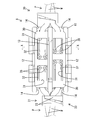
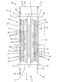
- Bottom view showing the state where no electric wire is connected to the connector
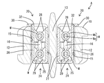
- Front view showing the state where no electric wire is connected to the connector
- the connector according to the present invention may be configured such that the expansion restricting portion extends from one of the support plate portions and is locked to the other support plate portion. According to this structure, the expansion displacement of a pair of support plate part can be controlled reliably.
- a locking hole is formed in one of the expansion restricting portion and the other support plate, and the other can be locked with the locking hole.
- a locking projection may be formed. According to this configuration, the expansion restricting portion and the other support plate portion can be reliably locked.
- the expansion restriction portion may restrict expansion at two positions sandwiching the press contact blade in the axial direction of the electric wire. According to this structure, it can control reliably that a press-contact blade leaves
- the connector A of the present embodiment has a function as a pressure-contact type joint connector A that targets a total of four electric wires W constituting a pair of twisted pair wires P as pressure contacts.
- the length direction of the twisted pair line P is defined as the front-rear direction. Further, it is assumed that a pair of twisted pair wires P are routed side by side.
- the connector A connects one electric wire W constituting the upper twisted pair wire P and one electric wire W constituting the lower twisted pair wire P so as to be conductive, and the other electric wire constituting the upper twisted pair wire P.
- the electric wire W and the other electric wire W which comprises the lower twisted pair wire P are connected so that conduction
- the electric wire W is a well-known one in which a conductor Wa is surrounded by an insulating coating Wb.
- the connector A includes a holder 10 and a pair of press contact terminal fittings 20.
- the holder 10 is made of synthetic resin, and has a pair of end wall portions 11 that are opposed to each other with a space in the front-rear direction, and a pair of left and right side wall portions 12 that connect the left and right edges of the pair of end wall portions 11.
- a single component including a single partition wall 13 that connects the central portions of the pair of end wall portions 11 in the left-right direction.
- the side wall part 12 and the partition part 13 are extended long in the front-back direction.
- a pair of left and right concave portions 14 each having a substantially semicircular shape are formed on the upper end edge and the lower end edge of the end wall portion 11.
- the recessed part 14 positions the electric wire W in the left-right direction.
- each attachment space 15 accommodates almost the entire pressure contact portion 24 described later.
- a beam portion 16 is disposed between the front and rear end wall portions 11. As shown in FIG. 3, the beam portion 16 regulates the downward displacement of the electric wire W pressed against the upper press-contact blade 28 described later, and the upward movement of the electric wire W pressed against the lower press-contact blade 29. It is to regulate.
- the pair of press contact terminal fittings 20 have the same shape and dimensions, and are arranged so as to be point-symmetric in plan view as shown in FIGS.
- the press-connecting terminal fitting 20 is a single part including an electric wire holding part 21 and a press-contacting part 24 elongated from the electric wire holding part 21 to the front.
- the electric wire holding portion 21 is composed of a horizontal receiving plate portion 22 having a substantially square shape in plan view, and a pair of crimping pieces 23 rising from the left and right side edges of the receiving plate portion 22. .
- the press contact portion 24 includes a substrate portion 25 that is elongated horizontally from the right end portion of the front end edge of the receiving plate portion 22 to the front, and a piece extending upward at a substantially right angle from the left edge of the substrate portion 25.
- a first support plate portion 26 that rises in a cantilever shape (one support plate portion in the claims), and a second support plate portion 27 that rises in a cantilever manner at a substantially right angle from the right edge of the substrate portion 25 (claims)
- the other support plate portion) and four pairs of press contact blades 28 and 29 are provided.
- one of the pair of press contact blades 28, 29 is substantially V-shaped in plan view to the inside (second support plate portion 27 side) by bending a part of the first support plate portion 26.
- the other of the pair of press contact blades 28 and 29 is a substantially V-shape in a plan view inward (first support plate portion 26 side) by bending a part of the second support plate portion 27. It is the form which protruded. That is, the press contact blades 28 and 29 are supported by the support plate portions 26 and 27.
- the four pairs of press contact blades 28 and 29 are arranged in two upper and lower stages.
- the two pairs of upper press contact blades 28 disposed on the upper side are disposed at a predetermined interval in the front and rear direction.
- the two pairs of lower press contact blades 29 arranged on the lower stage side are also arranged at a predetermined interval in the front-rear direction.
- the front upper press-contact blade 28 and the front lower press-contact blade 29 are arranged so as to be displaced in the front-rear direction.
- the rear upper press-contact blade 28 and the rear lower press-contact blade 29 are also displaced in the front-rear direction.
- the support plate portions 26 and 27 that support the press contact blades 28 and 29 extend in a cantilever shape from the substrate portion 25 so as to be separated from each other (outwardly). I am concerned that it will be deformed.
- the first support plate portion 26 is integrally provided with an expansion restricting portion 30 in a form that further extends in a cantilevered manner from the upper end edge (from the rising end edge). Is formed.
- the expansion restriction portion 30 extends upward in a substantially flush manner with the first support plate portion 26. It has become.
- the expansion restriction part 30 is formed with two front and rear locking holes 31.
- the two locking holes 31 are open so as to include a region sandwiching the front and rear upper press-contact blades 28 from the front and rear in the front and rear direction. That is, the front locking hole 31 opens so as to include a region in front of the front upper press-contacting blade 28, and the rear locking hole 31 has a region behind the rear upper press-contacting blade 28. Open to include.
- the second support plate portion 27 is integrally formed with two front and rear locking projections 32 protruding upward from the upper end edge (rising end edge) thereof.
- the assembly of the holder 10 and the press contact terminal fitting 20 is performed in parallel with the press contact process between the press contact terminal fitting 20 and the electric wire W.
- the two electric wires W constituting the lower twisted pair wire P are distributed to the left and right.
- one electric wire W is pressed against the press contact portion 24 of the one press contact terminal fitting 20, and the other electric wire W is pressed against the press contact portion 24 of the other press contact terminal fitting 20.
- the electric wire W is pushed between the pair of support plate portions 26 and 27 from above the press contact portion 24 and passed through the two front and rear pairs of upper press contact blades 28, and between the two front and rear pairs of lower press contact blades 29. Push into.
- the pair of lower press contact blades 29 are in contact with the conductor Wa so as to be sandwiched from both the left and right sides by cutting the insulating coating Wb. Thereby, the press-contact part 24 (press-contact terminal metal fitting 20) and the electric wire W are connected so that conduction
- the two press contact terminal fittings 20 are attached to the holder 10 from the lower side.
- the two pressure contact portions 24 are accommodated in the attachment space 15, respectively, and the electric wire W pressed against the lower pressure contact blade 29 is opposed or brought into contact with the beam portion 16 from below.
- the electric wire holding part 21 is disposed outside the attachment space 15 so as to correspond to the end wall part 11.
- the two electric wires W constituting the upper twisted pair wire P are distributed to the left and right. Then, one electric wire W is pressed against the press contact portion 24 of the one press contact terminal fitting 20, and the other electric wire W is pressed against the press contact portion 24 of the other press contact terminal fitting 20. At the time of press contact, the electric wire W is pressed between the pair of support plate portions 26 and 27 from above the press contact portion 24 and between the two front and rear upper press contact blades 28. Then, the pair of upper press contact blades 28 are in contact with the conductor Wa so as to be sandwiched from both the left and right sides by cutting the insulating coating Wb. Thereby, the press-contact part 24 (press-contact terminal metal fitting 20) and the electric wire W are connected so that conduction
- one of the electric wires W constituting the upper twisted-pair wire P and one of the electric wires W constituting the lower twisted-pair wire P are connected to one of the press-contacting terminal fittings 20 (the press-contacting portion 24).
- the electric wire W is connected (joint) so as to be conductive.
- the other wire W constituting the upper twisted pair wire P and the other wire W constituting the lower twisted pair wire P are connected to the other pressure contact terminal fitting 20 (pressure contact portion 24) so as to be conductive ( Joint).
- the four electric wires W are collectively held by the electric wire holding portion 21. That is, the four electric wires W (two pairs of twisted pair wires P) placed on the receiving plate portion 22 are surrounded by the two caulking pieces 23 paired on the left and right. As a result, the four electric wires W are held in pressure contact with the pressure contact portion 24, and the holder 10 and the two pressure contact terminal fittings 20 are fixed.
- the expansion restricting portion 30 is bent so as to be tilted at a substantially right angle toward the second support plate portion 27 side. Then, the two front and rear locking holes 31 are locked to the two front and rear locking protrusions 32. As a result, the first support plate portion 26 and the second support plate portion 27 are fixed so as not to be separated from each other, and the pressure contact blades 28 and 29 that are supported by the both support plate portions 26 and 27 and that make a pair are also prevented from being separated from each other left and right. Fixed to. Thus, the press contact blades 28 and 29 fixed so as not to be separated from each other are kept connected to the conductor at a predetermined contact pressure.
- the connector A includes the two press-contact terminal fittings 20 in which the press-contact portions 24 press-contacted to the electric wires W are formed.
- Each press-contact part 24 is formed so as to be supported by the substrate part 25, a pair of support plate parts 26 and 27 rising from both side edges of the substrate part 25, and the pair of support plate parts 26 and 27, respectively.
- four pairs of press contact blades 28, 29 are formed.
- the pair of press contact blades 28 and 29 sandwich the electric wire W pushed between the pair of support plate portions 26 and 27 so as to be conductive.
- the press-contact terminal fitting 20 is integrally formed with an expansion restricting portion 30 that restricts the pair of support plate portions 26 and 27 from expanding.
- the expansion displacement of the pair of support plate portions 26 and 27 is restricted by the expansion restriction portion 30.
- the press contact blades 28 and 29 which are supported by the pair of support plate portions 26 and 27 and make a pair maintain the state in which the electric wire W is securely sandwiched without being separated. Therefore, the connector A of this embodiment is excellent in contact reliability to the electric wire W by the press contact blades 28 and 29.
- the expansion restricting portion 30 is formed integrally with the press contact terminal fitting 20, the number of parts can be reduced as compared with the case where the expansion restricting portion is a separate component from the press contact terminal fitting 20. Yes.
- the expansion restricting portion 30 extends from the first support plate portion 26 and is locked to the second support plate portion 27, the expansion of the pair of support plate portions 26 and 27 can be simplified. Open displacement can be reliably controlled.
- a locking hole 31 is formed in the expansion restricting portion 30, and a locking projection 32 is formed in the second support plate portion 27, and the locking hole 31 and the locking projection 32 are locked. Therefore, the expansion restriction part 30 and the second support plate part 27 can be reliably locked.
- the expansion restricting portion 30 restricts the expansion at the front and rear two positions sandwiching the press contact blades 28 and 29 in the axial direction (front and rear direction) of the electric wire W. That is, the locking hole 31 and the locking projection 32 are locked at two positions, the front position and the rear position of the press contact blades 28 and 29. According to this configuration, separation of the press contact blades 28 and 29 can be reliably controlled.
- the expansion restricting portion extends from the first support plate portion (one support plate portion) and is locked to the second support plate portion (the other support plate portion).
- the opening restricting portion may extend from both of the pair of support plate portions, and the extended pair of expanding restricting portions may be engaged with each other.
- the locking hole formed in the expansion restricting portion is locked to the locking protrusion formed in the second support plate portion (the other support plate portion).
- the formed locking projection may be locked in a locking hole formed in the second support plate portion (the other support plate portion).
- the expansion restricting portion restricts the expansion at two positions sandwiching the press contact blade in the axial direction of the electric wire, but the expansion restricting portion is aligned with the press contact blade in the axial direction of the electric wire.
- the expansion may be restricted only at one place.
- one press contact portion is formed on one press contact terminal fitting, but a plurality of press contact portions may be formed on one press contact terminal fixture.
- four pairs of press contact blades are formed in one press contact portion, but the number of press contact blades formed in one press contact portion may be three pairs or less, or five pairs or more.
- the press contact blades are formed at two different positions in the rising direction of the support plate portion.
- the number of press contact blades arranged in the rising direction of the support plate portion may be three or more.
- the number of press contact blades arranged in the rising direction of the part may be only one.
- two press contact terminal fittings are attached to one holder, but the number of press contact terminal fittings attached to one holder may be one or three or more.
- the electric wire that is the object of pressure contact is an electric wire that forms a twisted pair wire, but the present invention can also be applied when the connection object is an electric wire that forms a conductive path other than the twisted pair wire.
- the example in which a plurality of (two) electric wires are connected in parallel by one press contact terminal fitting has been described.
- the present invention has one press contact terminal fitting. Only the electric wire is pressure-welded, and can also be applied to a connector attached to the end portion of the wire harness.
- the expansion restricting portion extends from the upper end edge (from the rising edge) of the outer edges of the first support plate portion, but the expansion restricting portion is the first support plate. It is good also as a form which extended from the edge part (front end edge or back end edge) which cross
- a window hole for inserting the electric wire, a notch for avoiding interference with the electric wire, or the like may be formed in the expansion restricting portion.
Landscapes
- Connections By Means Of Piercing Elements, Nuts, Or Screws (AREA)
Abstract
圧接刃による接触信頼性を高める。 コネクタ(A)は、電線(W)に圧接される圧接部(24)が形成された圧接端子金具(20)と、圧接部(24)を構成する基板部(25)と、基板部(25)の両側縁から立ち上がった形態であって圧接部(24)を構成する一対の支持板部(26,27)と、圧接部(24)を構成し、一対の支持板部(26,27)に支持されるように形成されて、一対の支持板部(26,27)の間に押し込まれた電線(W)を導通可能に挟み付ける一対の圧接刃(28,29)と、圧接端子金具(20)に一体に形成され、一対の支持板部(26,27)が拡開するのを規制する拡開規制部(30)とを備える。
Description
本発明は、コネクタに関するものである。
特許文献1には、ハウジングに圧接端子金具を取り付けたコネクタが開示されている。圧接端子金具の圧接部は、底板部の左右両側縁から一対の側板部を立ち上げ、両側板部の一部を内側へ切り起こすことによって圧接刃を形成した形態である。両側板部の間に被覆電線を押し込むと、圧接刃が絶縁被覆を切開して導体に接続するようになっている。
圧接部に電線を圧接した状態では、一対の圧接刃が導体を挟むことによって接触圧が確保されるため、一対の圧接刃が互いに離間するように変位することは好ましくない。しかし、一対の圧接刃を支持している一対の側板部は、底板部から片持ち状に立ち上がった形態であるため、外側へ傾くように変形する虞がある。一対の側板部が外側へ傾くことは、一対の圧接刃が離間することを意味するため、対策が必要である。
本発明は上記のような事情に基づいて完成されたものであって、圧接刃による接触信頼性を高めることを目的とする。
本発明のコネクタは、
電線に圧接される圧接部が形成された圧接端子金具と、
前記圧接部を構成する基板部と、
前記基板部の両側縁から立ち上がった形態であって、前記圧接部を構成する一対の支持板部と、
前記圧接部を構成し、前記一対の支持板部に支持されるように形成されて、前記一対の支持板部の間に押し込まれた前記電線を導通可能に挟み付ける一対の圧接刃と、
前記圧接端子金具に一体に形成され、前記一対の支持板部が拡開するのを規制する拡開規制部とを備えているところに特徴を有する。
電線に圧接される圧接部が形成された圧接端子金具と、
前記圧接部を構成する基板部と、
前記基板部の両側縁から立ち上がった形態であって、前記圧接部を構成する一対の支持板部と、
前記圧接部を構成し、前記一対の支持板部に支持されるように形成されて、前記一対の支持板部の間に押し込まれた前記電線を導通可能に挟み付ける一対の圧接刃と、
前記圧接端子金具に一体に形成され、前記一対の支持板部が拡開するのを規制する拡開規制部とを備えているところに特徴を有する。
一対の支持板部の拡開変位は拡開規制部によって規制されているので、一対の支持板部に支持されている一対の圧接刃は、離間することなく電線を確実に挟み付ける状態を保つ。したがって、本発明のコネクタは、圧接刃による電線への接触信頼性に優れている。また、拡開規制部は圧接端子金具に一体に形成されているので、部品点数が少なくて済む。
(a)本発明のコネクタは、前記拡開規制部が、一方の前記支持板部から延出して他方の前記支持板部に係止される形態であってもよい。この構成によれば、一対の支持板部の拡開変位を確実に規制することができる。
(b)本発明のコネクタは、(a)において、前記拡開規制部と前記他方の支持板のうち一方には係止孔が形成され、他方には、前記係止孔と係止可能な係止突起が形成されていてもよい。この構成によれば、拡開規制部と他方の支持板部とを確実に係止させることができる。
(c)本発明のコネクタは、前記拡開規制部が、前記電線の軸線方向において前記圧接刃を挟む2位置で拡開規制していてもよい。この構成によれば、圧接刃が離間することを確実に規制することができる。
<実施例1>
以下、本発明を具体化した実施例1を図1~図8を参照して説明する。本実施例のコネクタAは、一対のツイストペア線Pを構成する合計4本の電線Wを圧接対象とする圧接タイプのジョイントコネクタAとしての機能を有する。尚、以下の説明では、便宜上、ツイストペア線Pの長さ方向を、前後方向と定義する。また、一対のツイストペア線Pが上下に並んで配索されるものとする。コネクタAは、上側のツイストペア線Pを構成する一方の電線Wと、下側のツイストペア線Pを構成する一方の電線Wとを導通可能に接続し、上側のツイストペア線Pを構成する他方の電線Wと、下側のツイストペア線Pを構成する他方の電線Wとを導通可能に接続する。図3に示すように、電線Wは、導体Waを絶縁被覆Wbで包囲した周知のものである。
以下、本発明を具体化した実施例1を図1~図8を参照して説明する。本実施例のコネクタAは、一対のツイストペア線Pを構成する合計4本の電線Wを圧接対象とする圧接タイプのジョイントコネクタAとしての機能を有する。尚、以下の説明では、便宜上、ツイストペア線Pの長さ方向を、前後方向と定義する。また、一対のツイストペア線Pが上下に並んで配索されるものとする。コネクタAは、上側のツイストペア線Pを構成する一方の電線Wと、下側のツイストペア線Pを構成する一方の電線Wとを導通可能に接続し、上側のツイストペア線Pを構成する他方の電線Wと、下側のツイストペア線Pを構成する他方の電線Wとを導通可能に接続する。図3に示すように、電線Wは、導体Waを絶縁被覆Wbで包囲した周知のものである。
図5~8に示すように、コネクタAは、ホルダ10と、一対の圧接端子金具20とを備えて構成されている。ホルダ10は、合成樹脂製であり、前後方向に間隔を開けて対向配置された一対の端壁部11と、一対の端壁部11の左右両端縁同士を連結する左右一対の側壁部12と、一対の端壁部11の左右方向中央部同士を連結する1つの隔壁部13とを備えた単一部品である。側壁部12と隔壁部13は、前後方向に長く延びている。図5,8に示すように、端壁部11の上端縁と下端縁には、夫々、略半円形をなす左右一対ずつの凹部14が形成されている。凹部14は、電線Wを左右方向に位置決めするものである。
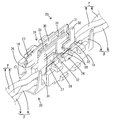
図6,7に示すように、ホルダ10のうち上記各壁部11,12,13で囲まれた左右2つの空間は、前後方向に長く且つ上下両面が開放された左右一対の取付け空間15となっている。各取付け空間15内には、夫々、後述する圧接部24のほぼ全体が収容されている。また、各取付け空間15内には、夫々、前後両端壁部11の間に差し渡された梁部16が配されている。図3に示すように、梁部16は、後述する上部圧接刃28に圧接された電線Wが下方へ変位することを規制するとともに、下部圧接刃29に圧接された電線Wが上方へ変位するのを規制するものである。
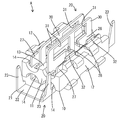
一対の圧接端子金具20は、形状と寸法が同一であり、図6,7に示すように、平面視において点対称となるように配されている。圧接端子金具20は、電線保持部21と、電線保持部21から前方へ細長く延びた圧接部24とを備えた単一部品である。図5,8に示すように、電線保持部21は、平面視略方形をなす水平な受け板部22と、受け板部22の左右両側縁から立ち上がる一対のカシメ片23とから構成されている。
図3,6に示すように、圧接部24は、受け板部22の前端縁における右端部から前方へ細長く水平に延びた基板部25と、基板部25の左側縁から略直角に上方へ片持ち状に立ち上がる第1支持板部26(請求項記載の一方の支持板部)と、基板部25の右側縁から略直角に上方へ片持ち状に立ち上がる第2支持板部27(請求項記載の他方の支持板部)と、四対の圧接刃28,29とを備えて構成されている。
図6に示すように、対をなす圧接刃28,29の一方は、第1支持板部26の一部を曲げ加工することにより内側(第2支持板部27側)へ平面視略V字形に突出した形態であり、対をなす圧接刃28,29の他方は、第2支持板部27の一部を曲げ加工することにより内側(第1支持板部26側)へ平面視略V字形に突出した形態である。つまり、圧接刃28,29は、支持板部26,27に支持された形態となっている。
図3,8に示すように、四対の圧接刃28,29は、上下2段に分かれて配されている。上段側に配された二対の上部圧接刃28は、前後に所定の間隔を開けて配されている。下段側に配された二対の下部圧接刃29も、前後に所定の間隔を開けて配されている。そして、図6に示すように、前側の上部圧接刃28と前側の下部圧接刃29は、前後方向に位置ずれして配置されている。後側の上部圧接刃28と後側の下部圧接刃29も前後方向に位置ずれして配置されている。
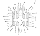
図3に示すように、圧接刃28,29を支持する支持板部26,27は、基板部25からほぼ平行に片持ち状に延出した形態であるため、互いに離間するように(外側へ倒れるように)変形することが懸念される。その対策として、図3,5に示すように、第1支持板部26には、その上端縁(立ち上がり端縁から)から更に片持ち状に延出した形態の拡開規制部30が、一体形成されている。圧接部24に電線Wを圧接する前の状態では、図5,8に示すように、拡開規制部30が、第1支持板部26とほぼ面一状をなして上方へ延出した形態となっている。拡開規制部30には、前後2つの係止孔31が形成されている。
図5に示すように、2つの係止孔31は、前後方向において前後両上部圧接刃28を前後から挟む領域を含むように開口している。つまり、前側の係止孔31は、前側の上部圧接刃28よりも前方の領域を含むように開口し、後側の係止孔31は、後側の上部圧接刃28よりも後方の領域を含むように開口している。また、第2支持板部27には、その上端縁(立ち上がり端縁)から上方へ突出した形態の前後2つの係止突起32が、一体に形成されている。
拡開規制部30を内側(第2支持板部27側)へ直角に曲げ加工した状態では、図1,2に示すように、2つの係止孔31と2との係止突起32が、夫々、係止するようになっている。そして、この係止孔31と係止突起32との係止作用により、第1支持板部26と第2支持板部27が、互いに離間する方向への変位を規制されるようになっている。
次に、本実施例の作用を説明する。ホルダ10と圧接端子金具20との組付けは、圧接端子金具20と電線Wとの圧接工程と並行して行われる。組付けに際しては、まず、下側のツイストペア線Pを構成する2本の電線Wを左右に振り分ける。そして、一方の電線Wを一方の圧接端子金具20の圧接部24に圧接するとともに、他方の電線Wを他方の圧接端子金具20の圧接部24に圧接する。圧接に際しては、電線Wを、圧接部24の上方から一対の支持板部26,27の間に押込み、前後二対の上部圧接刃28を通過させて、前後二対の下部圧接刃29の間に押し込む。対をなす下部圧接刃29は、絶縁被覆Wbを切開して導体Waに対し左右両側から挟むように当接する。これにより、圧接部24(圧接端子金具20)と電線Wとが導通可能に接続される。
上記のように、下側のツイストペア線Pを構成する2本の電線Wを、2つの圧接端子金具20に別々に圧接した後、2つの圧接端子金具20をホルダ10に対し下側から取り付ける。取付けに際しては、2つの圧接部24を、夫々、取付け空間15内に収容し、下部圧接刃29に圧接されている電線Wを、梁部16に対し下から対向又は当接させる。電線保持部21は、取付け空間15の外部において端壁部11と対応するように配置する。
この後、上側のツイストペア線Pを構成する2本の電線Wを左右に振り分ける。そして、一方の電線Wを一方の圧接端子金具20の圧接部24に圧接するとともに、他方の電線Wを他方の圧接端子金具20の圧接部24に圧接する。圧接に際しては、電線Wを、圧接部24の上方から一対の支持板部26,27の間に押込み、前後二対の上部圧接刃28の間に押し込む。すると、対をなす上部圧接刃28は、絶縁被覆Wbを切開して導体Waに対し左右両側から挟むように当接する。これにより、圧接部24(圧接端子金具20)と電線Wとが導通可能に接続される。
4本の電線Wが圧接されると、一方の圧接端子金具20(圧接部24)には、上側のツイストペア線Pを構成する一方の電線Wと、下側のツイストペア線Pを構成する一方の電線Wとが導通可能に接続(ジョイント)される。また、他方の圧接端子金具20(圧接部24)には、上側のツイストペア線Pを構成する他方の電線Wと、下側のツイストペア線Pを構成する他方の電線Wとが導通可能に接続(ジョイント)される。
4本の電線Wを全て圧接端子金具20に圧接した後は、電線保持部21で4本の電線Wを一括して保持する。即ち、受け板部22に載置した4本の電線W(二対のツイストペア線P)を、左右で対をなす両カシメ片23で包囲する。これにより、4本の電線Wが圧接部24と圧接した状態に保持されるとともに、ホルダ10と2つの圧接端子金具20が固定される。
また、電線保持部21で電線Wを保持する工程と前後して、拡開規制部30を、第2支持板部27側へ略直角に倒すように曲げ加工する。そして、前後2つの係止孔31を前後2つの係止突起32に係止させる。これにより、第1支持板部26と第2支持板部27が離間しないように固定され、両支持板部26,27に支持されて対をなす圧接刃28,29も、左右に離間しないように固定される。このように離間しないように固定された圧接刃28,29は、導体に対し所定の接触圧で接続された状態に保たれる。
上述のように、本実施例のコネクタAは、電線Wに圧接される圧接部24が形成された2つの圧接端子金具20を備える。各圧接部24は、夫々、基板部25と、基板部25の両側縁から立ち上がった形態の一対の支持板部26,27と、一対の支持板部26,27に支持されるように形成された四対の圧接刃28,29とを備える。対をなす圧接刃28,29は、一対の支持板部26,27の間に押し込まれた電線Wを導通可能に挟み付ける。そして、圧接端子金具20には、一対の支持板部26,27が拡開するのを規制する拡開規制部30が、一体に形成されている。
本実施例のコネクタAは、一対の支持板部26,27の拡開変位を拡開規制部30によって規制している。これにより、一対の支持板部26,27に支持されて対をなす圧接刃28,29は、離間することなく電線Wを確実に挟み付ける状態を保つ。したがって、本実施例のコネクタAは、圧接刃28,29による電線Wへの接触信頼性に優れている。また、拡開規制部30は圧接端子金具20に一体に形成されているので、拡開規制部を圧接端子金具20とは別体の部品とした場合に比べると、部品点数が少なくて済んでいる。
また、拡開規制部30は、第1支持板部26から延出して第2支持板部27に係止される形態であるから、シンプルな形状でも、一対の支持板部26,27の拡開変位を確実に規制することができる。特に、拡開規制部30には係止孔31を形成し、第2支持板部27には係止突起32を形成し、この係止孔31と係止突起32とを係止させているので、拡開規制部30と第2支持板部27とを確実に係止させることができる。
また、拡開規制部30は、電線Wの軸線方向(前後方向)において圧接刃28,29を挟む前後2位置で拡開規制している。つまり、圧接刃28,29の前方位置と後方位置の2箇所において、係止孔31と係止突起32とが係止している。この構成によれば、圧接刃28,29が離間することを確実に規制することができる。
<他の実施例>
本発明は上記記述及び図面によって説明した実施例に限定されるものではなく、例えば次のような実施例も本発明の技術的範囲に含まれる。
(1)上記実施例では、拡開規制部が、第1支持板部(一方の支持板部)から延出して第2支持板部(他方の支持板部)に係止されていが、拡開規制部は、一対の支持板部の両方から延出し、この延出した一対の拡開規制部同士を係止させる形態であってもよい。
(2)上記実施例では、拡開規制部に形成した係止孔を、第2支持板部(他方の支持板部)に形成した係止突起に係止させたが、拡開規制部に形成した係止突起を、第2支持板部(他方の支持板部)に形成した係止孔に係止させるようにしてもよい。
(3)上記実施例では、拡開規制部が、電線の軸線方向において圧接刃を挟む2位置で拡開規制するようにしたが、拡開規制部は、電線の軸線方向において圧接刃と並ぶ1箇所のみで拡開規制するようになっていてもよい。
(4)上記実施例では、1つの圧接端子金具に1つの圧接部が形成されているが、1つの圧接端子金具に複数の圧接部が形成されていてもよい。
(5)上記実施例では、1つの圧接部に四対の圧接刃を形成したが、1つの圧接部に形成する圧接刃の数は、三対以下でもよく、五対以上でもよい。
(6)上記実施例では、支持板部の立ち上がり方向において異なる2位置に圧接刃を形成しているが、支持板部の立ち上がり方向に並ぶ圧接刃の数を3つ以上としてもよく、支持板部の立ち上がり方向に配される圧接刃の数は、1つだけであってもよい。
(7)上記実施例では、1つのホルダに2つの圧接端子金具を取り付けたが、1つのホルダに取り付ける圧接端子金具の数は、1つでもよく、3つ以上でもよい。
(8)上記実施例では、圧接対象である電線がツイストペア線を構成する電線であるが、本発明は、接続対象が、ツイストペア線以外の導電路を構成する電線である場合にも適用できる。
(9)上記実施例では、1つの圧接端子金具によって複数本(2本)の電線を並列接続するジョイントコネクタに適用した例を説明したが、本発明は、1つの圧接端子金具が1本の電線のみを圧接するようになっていて、ワイヤーハーネスの端末部に取り付けられるコネクタにも適用できる。
(10)上記実施例では、拡開規制部が、第1支持板部の外縁のうち上端縁(立ち上がり端縁から)から延出した形態であるが、拡開規制部は、第1支持板部の外縁のうち上端縁と交差する縁部(前端縁又は後端縁)から延出した形態や、第1支持板部の一部を切り起こした形態としてもよい。この場合、拡開規制部に、電線を挿通させるための窓孔や、電線との干渉を回避するための切欠部等を形成してもよい。
本発明は上記記述及び図面によって説明した実施例に限定されるものではなく、例えば次のような実施例も本発明の技術的範囲に含まれる。
(1)上記実施例では、拡開規制部が、第1支持板部(一方の支持板部)から延出して第2支持板部(他方の支持板部)に係止されていが、拡開規制部は、一対の支持板部の両方から延出し、この延出した一対の拡開規制部同士を係止させる形態であってもよい。
(2)上記実施例では、拡開規制部に形成した係止孔を、第2支持板部(他方の支持板部)に形成した係止突起に係止させたが、拡開規制部に形成した係止突起を、第2支持板部(他方の支持板部)に形成した係止孔に係止させるようにしてもよい。
(3)上記実施例では、拡開規制部が、電線の軸線方向において圧接刃を挟む2位置で拡開規制するようにしたが、拡開規制部は、電線の軸線方向において圧接刃と並ぶ1箇所のみで拡開規制するようになっていてもよい。
(4)上記実施例では、1つの圧接端子金具に1つの圧接部が形成されているが、1つの圧接端子金具に複数の圧接部が形成されていてもよい。
(5)上記実施例では、1つの圧接部に四対の圧接刃を形成したが、1つの圧接部に形成する圧接刃の数は、三対以下でもよく、五対以上でもよい。
(6)上記実施例では、支持板部の立ち上がり方向において異なる2位置に圧接刃を形成しているが、支持板部の立ち上がり方向に並ぶ圧接刃の数を3つ以上としてもよく、支持板部の立ち上がり方向に配される圧接刃の数は、1つだけであってもよい。
(7)上記実施例では、1つのホルダに2つの圧接端子金具を取り付けたが、1つのホルダに取り付ける圧接端子金具の数は、1つでもよく、3つ以上でもよい。
(8)上記実施例では、圧接対象である電線がツイストペア線を構成する電線であるが、本発明は、接続対象が、ツイストペア線以外の導電路を構成する電線である場合にも適用できる。
(9)上記実施例では、1つの圧接端子金具によって複数本(2本)の電線を並列接続するジョイントコネクタに適用した例を説明したが、本発明は、1つの圧接端子金具が1本の電線のみを圧接するようになっていて、ワイヤーハーネスの端末部に取り付けられるコネクタにも適用できる。
(10)上記実施例では、拡開規制部が、第1支持板部の外縁のうち上端縁(立ち上がり端縁から)から延出した形態であるが、拡開規制部は、第1支持板部の外縁のうち上端縁と交差する縁部(前端縁又は後端縁)から延出した形態や、第1支持板部の一部を切り起こした形態としてもよい。この場合、拡開規制部に、電線を挿通させるための窓孔や、電線との干渉を回避するための切欠部等を形成してもよい。
W…電線
A…コネクタ
10…ホルダ
20…圧接端子金具
24…圧接部
25…基板部
26…第1支持板部(一方の支持板部)
27…第2支持板部(他方の支持板部)
28…上部圧接刃(圧接刃)
29…下部圧接刃(圧接刃)
30…拡開規制部
31…係止孔
32…係止突起
A…コネクタ
10…ホルダ
20…圧接端子金具
24…圧接部
25…基板部
26…第1支持板部(一方の支持板部)
27…第2支持板部(他方の支持板部)
28…上部圧接刃(圧接刃)
29…下部圧接刃(圧接刃)
30…拡開規制部
31…係止孔
32…係止突起
Claims (4)
- 電線に圧接される圧接部が形成された圧接端子金具と、
前記圧接部を構成する基板部と、
前記基板部の両側縁から立ち上がった形態であって、前記圧接部を構成する一対の支持板部と、
前記圧接部を構成し、前記一対の支持板部に支持されるように形成されて、前記一対の支持板部の間に押し込まれた前記電線を導通可能に挟み付ける一対の圧接刃と、
前記圧接端子金具に一体に形成され、前記一対の支持板部が拡開するのを規制する拡開規制部とを備えていることを特徴とするコネクタ。 - 前記拡開規制部が、一方の前記支持板部から延出して他方の前記支持板部に係止される形態であることを特徴とする請求項1記載のコネクタ。
- 前記拡開規制部と前記他方の支持板のうち一方には係止孔が形成され、他方には、前記係止孔と係止可能な係止突起が形成されていることを特徴とする請求項2記載のコネクタ。
- 前記拡開規制部が、前記電線の軸線方向において前記圧接刃を挟む2位置で拡開規制していることを特徴とする請求項1ないし請求項3のいずれか1項に記載のコネクタ。
Applications Claiming Priority (2)
| Application Number | Priority Date | Filing Date | Title |
|---|---|---|---|
| JP2015026277A JP2016149289A (ja) | 2015-02-13 | 2015-02-13 | コネクタ |
| JP2015-026277 | 2015-02-13 |
Publications (1)
| Publication Number | Publication Date |
|---|---|
| WO2016129387A1 true WO2016129387A1 (ja) | 2016-08-18 |
Family
ID=56615553
Family Applications (1)
| Application Number | Title | Priority Date | Filing Date |
|---|---|---|---|
| PCT/JP2016/052243 Ceased WO2016129387A1 (ja) | 2015-02-13 | 2016-01-27 | コネクタ |
Country Status (2)
| Country | Link |
|---|---|
| JP (1) | JP2016149289A (ja) |
| WO (1) | WO2016129387A1 (ja) |
Citations (3)
| Publication number | Priority date | Publication date | Assignee | Title |
|---|---|---|---|---|
| JP2000200630A (ja) * | 1998-10-26 | 2000-07-18 | Harness Syst Tech Res Ltd | 圧接端子 |
| JP2000268896A (ja) * | 1999-03-17 | 2000-09-29 | Harness Syst Tech Res Ltd | 圧接端子 |
| JP2002141119A (ja) * | 2000-11-01 | 2002-05-17 | Sumitomo Wiring Syst Ltd | 圧接端子金具 |
-
2015
- 2015-02-13 JP JP2015026277A patent/JP2016149289A/ja active Pending
-
2016
- 2016-01-27 WO PCT/JP2016/052243 patent/WO2016129387A1/ja not_active Ceased
Patent Citations (3)
| Publication number | Priority date | Publication date | Assignee | Title |
|---|---|---|---|---|
| JP2000200630A (ja) * | 1998-10-26 | 2000-07-18 | Harness Syst Tech Res Ltd | 圧接端子 |
| JP2000268896A (ja) * | 1999-03-17 | 2000-09-29 | Harness Syst Tech Res Ltd | 圧接端子 |
| JP2002141119A (ja) * | 2000-11-01 | 2002-05-17 | Sumitomo Wiring Syst Ltd | 圧接端子金具 |
Also Published As
| Publication number | Publication date |
|---|---|
| JP2016149289A (ja) | 2016-08-18 |
Similar Documents
| Publication | Publication Date | Title |
|---|---|---|
| TWI746658B (zh) | 用於接觸電導線的彈簧緊接觸件、接線端子和用於製造彈簧夾緊接觸件的方法 | |
| JP4372138B2 (ja) | 電気接点 | |
| DK3235067T3 (en) | CONNECTORS AND PROCEDURE FOR MANUFACTURING THIS CONNECTOR. | |
| KR101529682B1 (ko) | 조인트 커넥터 | |
| US9799980B2 (en) | Contact for electrical connectors | |
| JP6397864B2 (ja) | 分岐コネクタ | |
| JP2022104904A (ja) | 高電圧接続用端子本体、ケーブル・アセンブリおよびコネクタ | |
| JP6495216B2 (ja) | 分岐コネクタ | |
| JP2011029125A (ja) | 圧接コネクタ | |
| JP6358125B2 (ja) | コネクタ | |
| CN111194512A (zh) | 电线保持部件 | |
| JP5800624B2 (ja) | 電気接続箱のバスバー端部構造 | |
| JP2000133012A (ja) | 多灯照明具の接続構造 | |
| JP4246131B2 (ja) | 電線と素子内蔵ユニットとの接続構造 | |
| JP6812917B2 (ja) | 端子金具 | |
| JPH1116612A (ja) | 電線の接続構造 | |
| WO2014068847A1 (ja) | 圧接コンタクト及びコネクタ | |
| JP7339018B2 (ja) | 圧接端子、端子付き電線、及び、コネクタ | |
| JP7311309B2 (ja) | コネクタ | |
| JP2016149289A (ja) | コネクタ | |
| JP6643064B2 (ja) | 同軸ケーブルコネクタ、キャリア付き同軸ケーブルコネクタ及び同軸ケーブルコネクタの製造方法 | |
| JP2001110466A (ja) | 圧接コネクタ | |
| JP2019079782A (ja) | 分岐コネクタ及び通信ネットワーク | |
| JP7360310B2 (ja) | コンタクトおよびコネクタ | |
| JP6718704B2 (ja) | 圧接コネクタ |
Legal Events
| Date | Code | Title | Description |
|---|---|---|---|
| 121 | Ep: the epo has been informed by wipo that ep was designated in this application |
Ref document number: 16749032 Country of ref document: EP Kind code of ref document: A1 |
|
| NENP | Non-entry into the national phase |
Ref country code: DE |
|
| 122 | Ep: pct application non-entry in european phase |
Ref document number: 16749032 Country of ref document: EP Kind code of ref document: A1 |