WO2016129153A1 - 触媒構造体、触媒構造体の製造方法および製造装置 - Google Patents
触媒構造体、触媒構造体の製造方法および製造装置 Download PDFInfo
- Publication number
- WO2016129153A1 WO2016129153A1 PCT/JP2015/080710 JP2015080710W WO2016129153A1 WO 2016129153 A1 WO2016129153 A1 WO 2016129153A1 JP 2015080710 W JP2015080710 W JP 2015080710W WO 2016129153 A1 WO2016129153 A1 WO 2016129153A1
- Authority
- WO
- WIPO (PCT)
- Prior art keywords
- catalyst
- porous body
- catalyst structure
- main surface
- reformed gas
- Prior art date
- Legal status (The legal status is an assumption and is not a legal conclusion. Google has not performed a legal analysis and makes no representation as to the accuracy of the status listed.)
- Ceased
Links
Images





Classifications
-
- B—PERFORMING OPERATIONS; TRANSPORTING
- B01—PHYSICAL OR CHEMICAL PROCESSES OR APPARATUS IN GENERAL
- B01J—CHEMICAL OR PHYSICAL PROCESSES, e.g. CATALYSIS OR COLLOID CHEMISTRY; THEIR RELEVANT APPARATUS
- B01J35/00—Catalysts, in general, characterised by their form or physical properties
- B01J35/50—Catalysts, in general, characterised by their form or physical properties characterised by their shape or configuration
- B01J35/56—Foraminous structures having flow-through passages or channels, e.g. grids or three-dimensional [3D] monoliths
-
- B—PERFORMING OPERATIONS; TRANSPORTING
- B01—PHYSICAL OR CHEMICAL PROCESSES OR APPARATUS IN GENERAL
- B01J—CHEMICAL OR PHYSICAL PROCESSES, e.g. CATALYSIS OR COLLOID CHEMISTRY; THEIR RELEVANT APPARATUS
- B01J37/00—Processes, in general, for preparing catalysts; Processes, in general, for activation of catalysts
- B01J37/02—Impregnation, coating or precipitation
-
- C—CHEMISTRY; METALLURGY
- C01—INORGANIC CHEMISTRY
- C01B—NON-METALLIC ELEMENTS; COMPOUNDS THEREOF; METALLOIDS OR COMPOUNDS THEREOF NOT COVERED BY SUBCLASS C01C
- C01B3/00—Hydrogen; Gaseous mixtures containing hydrogen; Separation of hydrogen from mixtures containing it; Purification of hydrogen; Reversible storage of hydrogen
- C01B3/02—Production of hydrogen; Production of gaseous mixtures containing hydrogen
- C01B3/32—Production of hydrogen; Production of gaseous mixtures containing hydrogen by reaction of gaseous or liquid organic compounds with gasifying agents, e.g. water, carbon dioxide or air
- C01B3/34—Production of hydrogen; Production of gaseous mixtures containing hydrogen by reaction of gaseous or liquid organic compounds with gasifying agents, e.g. water, carbon dioxide or air by reaction of hydrocarbons with gasifying agents
- C01B3/38—Production of hydrogen; Production of gaseous mixtures containing hydrogen by reaction of gaseous or liquid organic compounds with gasifying agents, e.g. water, carbon dioxide or air by reaction of hydrocarbons with gasifying agents using catalysts
-
- C—CHEMISTRY; METALLURGY
- C01—INORGANIC CHEMISTRY
- C01B—NON-METALLIC ELEMENTS; COMPOUNDS THEREOF; METALLOIDS OR COMPOUNDS THEREOF NOT COVERED BY SUBCLASS C01C
- C01B3/00—Hydrogen; Gaseous mixtures containing hydrogen; Separation of hydrogen from mixtures containing it; Purification of hydrogen; Reversible storage of hydrogen
- C01B3/50—Separation of hydrogen or hydrogen-containing gases from gaseous mixtures, e.g. purification
- C01B3/56—Separation of hydrogen or hydrogen-containing gases from gaseous mixtures, e.g. purification by contacting with solids; Regeneration of used solids
-
- Y—GENERAL TAGGING OF NEW TECHNOLOGICAL DEVELOPMENTS; GENERAL TAGGING OF CROSS-SECTIONAL TECHNOLOGIES SPANNING OVER SEVERAL SECTIONS OF THE IPC; TECHNICAL SUBJECTS COVERED BY FORMER USPC CROSS-REFERENCE ART COLLECTIONS [XRACs] AND DIGESTS
- Y02—TECHNOLOGIES OR APPLICATIONS FOR MITIGATION OR ADAPTATION AGAINST CLIMATE CHANGE
- Y02P—CLIMATE CHANGE MITIGATION TECHNOLOGIES IN THE PRODUCTION OR PROCESSING OF GOODS
- Y02P20/00—Technologies relating to chemical industry
- Y02P20/50—Improvements relating to the production of bulk chemicals
- Y02P20/52—Improvements relating to the production of bulk chemicals using catalysts, e.g. selective catalysts
Definitions
- the present invention relates to a catalyst structure for generating a reformed gas by reforming a raw material gas with a catalyst, and a manufacturing technique of the catalyst structure.
- This membrane reactor has a multiple tube structure in which a hydrogen separation tube is arranged in a reaction tube (outer tube).
- a reforming catalyst such as particles is filled between the reaction tube and the hydrogen separation tube to form a reforming catalyst layer.
- a raw material gas containing a hydrocarbon gas is supplied to the reforming catalyst layer, the raw material gas is reformed by the reforming catalyst layer to generate a reformed gas containing hydrogen.
- hydrogen is separated from the reformed gas by a hydrogen permeable membrane such as a palladium (Pd) membrane provided in the hydrogen separation tube. In this way, hydrogen is purified.
- a hydrogen permeable membrane such as a palladium (Pd) membrane provided in the hydrogen separation tube.
- the reforming catalyst is filled between the reaction tube and the hydrogen separation tube, so that the reforming catalyst is in contact with the entire surface of the hydrogen permeable membrane provided in the hydrogen separation tube. .
- Such a problem is the same when not only the multi-tube structure but also a flat plate structure is adopted.
- the present invention has been made in view of the above problems, and a catalyst structure that can efficiently supply a raw material gas to a catalyst and take out the reformed gas to increase the efficiency of the reforming process, and the catalyst structure It aims at providing the manufacturing technique which manufactures a body.
- a first aspect of the present invention is a catalyst structure that generates a reformed gas by reforming a source gas with a catalyst, and the source gas and the reformed gas between a first main surface and a second main surface that are different from each other.
- the catalyst is partially supported inside a porous body having a three-dimensional network structure through which the catalyst can circulate.
- the second aspect of the present invention is a method for producing a catalyst structure, wherein a reformed raw material gas is reformed by a catalyst to generate a reformed gas, and the first and second main surfaces are different from each other.
- a fluid material containing a catalyst is supplied from the first main surface side to the porous body having a three-dimensional network structure through which the raw material gas and the reformed gas can flow, and the catalyst is partially inside the porous body. It has the 1st process to carry
- a third aspect of the present invention is a catalyst structure manufacturing apparatus for generating a reformed gas by reforming a raw material gas with a catalyst, between a first main surface and a second main surface that are different from each other.
- a catalyst support forming part for forming a catalyst support part for supplying a fluid material containing the catalyst to the inside of the porous body.
- the catalyst is partially supported inside the porous body.
- a supporting region for supporting the catalyst and a non-supporting region for not supporting the catalyst are provided inside the porous body.
- a reforming process using a catalyst is performed in the supporting region.
- the unsupported region the three-dimensional network structure is maintained, and the raw material gas and the reformed gas can be circulated. For this reason, supply of the raw material gas to the carrying region and removal of the reformed gas are executed through the non-carrying region, and as a result, the reformed gas can be generated efficiently.
- a plurality of constituent elements of each aspect of the present invention described above are not essential, and some or all of the effects described in the present specification are to be solved to solve part or all of the above-described problems.
- technical features included in one embodiment of the present invention described above A part or all of the technical features included in the above-described other aspects of the present invention may be combined to form an independent form of the present invention.
- FIG. 1 is a perspective view showing a first embodiment of a catalyst structure according to the present invention. It is a figure which shows schematic structure of the manufacturing apparatus which manufactures the catalyst structure of FIG. It is a figure which shows the structure of the coating unit contained in the manufacturing apparatus of FIG. It is an enlarged view which shows the structure of the head part with which the application
- FIG. 1 is a perspective view showing a first embodiment of a catalyst structure according to the present invention.
- a broken line portion in the figure is an enlarged view of a partial cross section.
- the catalyst structure 10 ⁇ / b> A includes a flat plate-like or sheet-like porous body 11 and a catalyst carrier 12 that partially supports the catalyst inside the porous body 11.
- the porous body 11 is formed of a material having no catalytic activity.
- a three-dimensional network structure is formed inside the porous body 11, and the raw material gas and the reformed gas can flow between the upper surface 11a and the lower surface 11b.
- the “three-dimensional network structure” means a mesh shape in which a large number of pores (see reference numeral 11c in FIG. 1) are arranged three-dimensionally and have substantially no coarse and independent pores. Means the structure.
- a foam metal, particularly stainless steel foam metal such as SUS304, SUS316, and SUS316L is used as the porous body 11 in consideration of the use environment.
- the porous body 11 is made of a material having no catalytic activity. If there is, it will not be specifically limited.
- a supporting region 11f that supports the catalyst is formed in a part of the plurality of hole portions by the manufacturing apparatus 1A described below, and is formed in a line shape, a strip shape, or a rod shape that extends in the X direction by the supporting region 11f.
- a catalyst carrier 12 is formed inside the porous body 11.
- the four catalyst support portions 12 are arranged while being separated from each other in the Y direction, but the shape, the number, the arrangement, and the like are arbitrary.
- the manufacturing apparatus 1A for manufacturing the catalyst structure 10A and the manufacturing procedure by the apparatus 1A will be described with reference to FIGS. 2 to 5, and the characteristics of the catalyst structure 10A will also be clarified.
- FIG. 2 is a diagram showing a schematic configuration of a production apparatus for producing the catalyst structure of FIG.
- FIG. 3 is a diagram showing a configuration of a coating unit included in the manufacturing apparatus of FIG.
- FIG. 4 is an enlarged view showing in more detail the configuration of the head unit equipped in the coating unit of FIG.
- FIG. 5 is a schematic diagram for explaining a method for producing a catalyst structure by the apparatus of FIG.
- the manufacturing apparatus 1A for manufacturing the catalyst structure 10A includes a coating unit 100, a drying unit 200, a press unit 300, four transport units 400a to 400d, and a control unit 500.
- the control unit 500 controls each part of the apparatus according to a preset program, so that the porous body 11 is transported in the order of the coating unit 100, the drying unit 200, and the press unit 300 by the transport units 400a to 400d. Then, a drying process and a pressing process are performed, whereby the catalyst structure 10A shown in FIG. 1 is manufactured.
- the configurations of the drying unit 200, the press unit 300, the transport units 400a to 400d, and the control unit 500 are well known and will not be described.
- the application unit 100 is a unit for applying a fluid material containing a catalyst to the porous body 11 to permeate the inside of the porous body 11 and partially supporting the catalyst.
- a stage moving mechanism 104 is provided on the base 102, and the stage 106 holding the porous body 11 can be moved in the XY plane by the stage moving mechanism 104. It has become.
- a frame 108 is fixed to the base 102 so as to straddle the stage 106, and a head unit 110 is attached to the frame 108.
- the stage moving mechanism 104 has an X direction moving mechanism 112 that moves the stage 106 in the X direction from the lower stage and a Y direction moving mechanism 114 that moves in the Y direction.
- the X-direction moving mechanism 112 has a structure in which a ball screw 118 is connected to a motor 116, and a nut 120 fixed to the Y-direction moving mechanism 114 is attached to the ball screw 118.
- the guide rail 122 is fixed above the ball screw 118 and the motor 116 rotates, the Y-direction moving mechanism 114 moves smoothly along the guide rail 122 in the X direction along with the nut 120.
- the Y-direction moving mechanism 114 also has a motor 124, a ball screw mechanism (not shown), and a guide rail 126.
- the motor 124 rotates, the stage 106 moves in the Y direction along the guide rail 126 by the ball screw mechanism.
- the relative movement direction of the head part 110 with respect to the porous body 11 can be changed.
- Each motor of the stage moving mechanism 104 is controlled by a control unit 500 that controls the entire apparatus. Note that a dedicated control unit for controlling the coating unit 100 may be provided, and the control unit may control each unit of the coating unit 100 in response to a command from the control unit 500.
- a discharge nozzle part 130 for discharging a fluid material prepared in advance is provided on the lower surface of the base 128.
- a supply pipe 132 is attached to the discharge nozzle unit 130.
- the supply pipe 132 is connected to a tank 140 that stores a fluid material containing a catalyst via a control valve 134, a pump 136, and a flow meter 138.
- the control unit 500 drives the pump 136 and controls the opening and closing of the control valve 134, thereby controlling the on / off of the flowable material discharge from the discharge nozzle portion 130.
- FIG. 4 is an enlarged view showing the configuration of the head part in more detail, and shows the vicinity of the tip of the discharge nozzle part 130 when the head part 110 is viewed from below.
- the discharge nozzle part 130 has a plurality of cylindrical tip nozzles 146 each having a discharge port 144 communicated with the nozzle base 142 having a cylindrical hollow inside (in this example, four nozzles are provided. It is not limited), and has a structure projecting at equal intervals in the Y direction.
- the fluid material transported from the tank 140 via the supply pipe 132 is discharged from the discharge port 144 at the lower end of the tip nozzle 146 toward the upper surface 11a of the porous body 11.
- the tip nozzle 146 extends from the nozzle base 142 in the ( ⁇ Z) direction and the (+ X) direction.
- the material of the tip nozzle 146 is not particularly limited.
- a crystal of silicon or zirconia is used from the viewpoint that the flowable material discharged from the discharge port 144 can be finely processed without mixing contaminants. Can do.
- the plurality of tip nozzles 146 provided in the head portion 110 are all the same shape. By making all the shapes of the tip nozzles that require such fine processing the same, it is possible to reduce the processing cost of the tip nozzles, and consequently the cost of the entire apparatus.
- a catalyst having a particle size (reference numeral 13 in FIG. 5) is used. More specifically, powdery silica (SiO 2 ), alumina (Al 2 O 3 ), titanium oxide (TiO 2 ) or the like having a particle size of 1 to 100 [ ⁇ m] is used as a catalyst carrier. Further, in order to exert the catalytic function by the catalyst 13, in the present embodiment, simple elements such as gold (Au), platinum (Pt), palladium (Pd) having a smaller diameter than the catalyst carrier, their oxides or hydroxides are used. The product is used as catalyst particles.
- a paste-like fluid material is prepared by mixing the catalyst 13 and a liquid component such as water or an organic solvent, and the fluid material is stored in the tank 140 (FIG. 3). deep.
- the transfer robot 400a carries the porous body 11 into the coating unit 100, and as shown in the column (a) in FIG. It is mounted on the stage 106 in a state facing (+ Z) (carrying-in process).
- the porous body 11 is held on the stage 106.
- the porous body 11 has a three-dimensional network structure, and a plurality of pores 11 c are provided inside the porous body 11. Further, the thickness T1 of the porous body 11 at this stage, that is, the distance between the upper surface 11a and the lower surface 11b in the vertical direction Z is set to be relatively thick. Moreover, in this embodiment, the porous body 11 with a porosity of 50% or more is used.
- the stage moving mechanism 104 operates to move the porous body 11 to a predetermined coating start position (position of the porous body 11 in FIG. 3) such that the right end of the porous body 11 comes to a position immediately below the head portion 110. Move. Next, while the porous body 11 is moved in the X direction, the flowable material discharge from the discharge nozzle portion 130 provided in the head portion 110 is started.
- the fluid material is continuously and stick-shapedly discharged from the tip nozzle 142 and supplied to the upper surface 11a of the porous body 11 with the width in the Y direction of the discharge port 144, that is, the line width W, as shown in the column (b) of FIG. Is done. Then, the fluid material flows through the porous body 11 included in the line width W and spreads toward the lower surface 11b.
- dots are given at a relatively fine pitch with respect to the hole portions 11c containing the fluid material. The same applies to FIG. 6 described later.
- the region in the porous body 11 that receives the fluid material as described above and supports the catalyst that is, the supporting region 11d extends in the X direction as the porous body 11 moves in the X direction. Then, the fluid material is applied in the form of a plurality of strips (four in this example) parallel to each other.
- the region 11e that does not receive the fluid material and does not permeate the fluid material in the porous body 11 is referred to as a “non-supported region”.
- the above operation is performed by returning to the application start position until the formation of the belt-shaped support region 11d on the entire surface of the porous body 11 is completed. Repeat as many times as necessary. At this time, by moving the position of the porous body 11 by a predetermined amount in the Y direction every time one operation is completed, a larger number of supporting regions 11d than the number of discharge ports 144 can be formed.
- the transport robot 400b transports the porous body 11 from the coating unit 100 to the drying unit 200.
- this drying unit 200 heat is applied to the porous body 11, and the liquid component contained in the fluid material is removed (drying process).
- a catalyst structure having a part of the catalyst support 12 for supporting the catalyst 13 inside the porous body 11 can be obtained, and this may be used as a final product.
- a relatively large gap is formed around the catalyst 13 in each hole portion 11c by removing the liquid component. For this reason, the catalyst 13 cannot always be said to be stably supported on the porous body 11, and may drop off from the porous body 11. Therefore, in this embodiment, when the drying process is completed, the transfer robot 400c transfers the porous body 11 from the drying unit 200 to the press unit 300.
- the supporting region 11f that firmly supports the catalyst 13 on the porous body 11 is extended in the X direction in a line shape or a belt shape, and these four supporting regions 11f become the catalyst supporting portion 12.
- a non-supporting region 11g that does not support the catalyst 13 is formed between the supporting regions 11f adjacent to each other, and the hole portion 11c included in the non-supporting region 11g circulates the source gas and the reformed gas. Functions as a flow path.
- the catalyst structure 10A is unloaded and accommodated in a reaction vessel of the reformer as a reforming catalyst for producing various devices, for example, reformed gas.
- the fluid material is applied in a band shape to a part of the porous body 11 having a three-dimensional network structure, and the catalyst 13 is partially supported inside the porous body 11. .
- a line-and-space structure in which the supporting regions 11 f and the non-supporting regions 11 g are alternately arranged in the Y direction is formed in the porous body 11.
- the catalyst 13 is supported on the supporting region 11f and functions as the catalyst supporting part 12.
- the non-supporting region 11g the three-dimensional network structure is maintained as it is and becomes a flow path for the source gas and the reformed gas.
- the source gas supplied via the upper surface 11a and the lower surface 11b of the porous body 11 is supplied to the supporting region 11f (catalyst supporting portion 12) via the non-supporting region 11g and is reformed by the catalyst 13.
- the reformed gas containing hydrogen generated in the supporting region 11f flows through the non-supporting region 11g and is taken out from the upper surface 11a and the lower surface 11b of the porous body 11. Therefore, the raw material gas and the reformed gas can be efficiently circulated using the unsupported region 11g in this way, and the reformed gas can be efficiently generated and taken out.
- the catalyst 13 since the catalyst 13 is supported in the pores 11c formed inside the porous body 11, the catalyst 13 can be prevented from falling off during the reforming process. . Moreover, the catalyst 13 is not only supported but also compressed as shown in the column (d) of FIG. For this reason, it is possible to more effectively prevent the catalyst 13 from falling off, and a more stable reforming process can be performed.
- FIG. 6 is a perspective view showing another embodiment of the catalyst structure manufacturing apparatus according to the present invention.
- the manufacturing apparatus 1B is greatly different from the manufacturing apparatus 1A in that the coating process, the drying process, and the pressing process are continuously performed in one apparatus (unit).
- the pressing process is performed in the same manner as in the first embodiment.
- the schematic diagram shown at the bottom of the figure schematically shows the inside of the porous body 11 before the coating process, between the coating process and the drying process, between the drying process and the pressing process, and after the pressing process, respectively.
- the catalyst structure manufacturing apparatus 1 ⁇ / b> B includes a coating unit 600 that performs a coating process, a drying unit 700 that performs a drying process, a roller press unit 800 that performs a pressing process, and a sheet-like porous body 11.
- the conveyance part 900 which conveys is provided.
- the transport unit 900 has a plurality of transport rollers 901 arranged in the X direction, and is porous by rotating the transport roller 901 in accordance with a transport command from a control unit (not shown) that controls the entire apparatus.
- the body 11 is conveyed in the X direction while maintaining a substantially horizontal posture.
- an application unit 600, a drying unit 700, and a roller press unit 800 are arranged in this order above the transport unit 900 along the transport path of the porous body 11.
- the coating unit 600 includes a discharge nozzle unit 601 having a plurality of (four in the present embodiment) discharge ports in the same manner as the coating unit 100.
- the discharge nozzle unit 601 is supplied with a flowable material containing a catalyst from a flowable material supply unit (not shown), and the flowable material is conveyed from each discharge port in the X direction while being supported by a plurality of conveyance rollers 901.
- the sheet-like porous body 11 is discharged onto the upper surface 11a.
- the fluid material is applied to the porous body 11 (application process), and in a part of the porous body 11, the fluid material penetrates into the pores 11c and extends in the X direction. Is formed inside the porous body 11.
- the drying unit 700 has a heating mechanism 701 that heats the porous body 11 conveyed by the roller from the coating unit 600.
- the liquid component contained in the fluid material is removed by the heating by the heating mechanism 701 (drying process).
- the roller press unit 800 includes a pair of press rollers 801 and 801 that are spaced apart in the vertical direction Z by an interval T2 that is narrower than the initial thickness T1 of the porous body 11, and these press rollers. And a drive mechanism (not shown) that rotationally drives 801 and 801.
- the press rollers 801 and 801 are driven to rotate by operating the drive mechanism in accordance with a rotation command from the control unit.
- the porous body 11 is conveyed to the roller press unit 800 through the drying process, the porous body 11 is compressed in the vertical direction Z from the thickness T1 to the thickness T2 when passing between the press rollers 801 and 801. (Pressing process).
- the support region 11f that firmly supports the catalyst 13 on the porous body 11 is extended in the X direction in a line shape or a strip shape, and the catalyst support portion is formed by these four support regions 11f.
- the catalyst structure 10B in which 12 is configured is manufactured.
- a non-supporting region 11g that does not support the catalyst 13 is formed between the supporting regions 11f adjacent to each other, and the hole portion 11c included in the non-supporting region 11g allows the source gas and the reformed gas to flow. Functions as a flow path.
- the second embodiment is configured in the same manner as the first embodiment and has the same effects. That is, the line and space structure in which the supporting regions 11f and the non-supporting regions 11g are alternately arranged in the Y direction by partially supporting the catalyst 13 inside the porous body 11 having a three-dimensional network structure is porous. Formed on the body 11. For this reason, the reformed gas can be generated in the supporting region 11f while the raw material gas and the reformed gas are efficiently circulated through the non-supported region 11g, and the generation efficiency and the extraction efficiency of the reformed gas can be increased. Further, since the catalyst 13 is supported in the air holes 11c and the catalyst 13 is in close contact by the pressing process, it is possible to effectively prevent the catalyst 13 from dropping and to perform the reforming process more stably. It has become.
- the application process, the drying process, and the pressing process can be performed in parallel while the porous body 11 is transported in the X direction by rollers, so that productivity can be improved.
- a porous body roll (not shown) in which a long porous body 11 extending in the X direction is wound into a roll shape is prepared, and the porous body 11 is fed out from the porous body roll.
- You may manufacture a catalyst structure continuously with the manufacturing apparatus 1B.
- the sheet-like catalyst structure produced in this way may be wound up in a roll shape, or may be cut off at a predetermined length to produce a flat or sheet-like catalyst structure 10A as shown in FIG. .
- FIG. 7 is a view showing a second embodiment of the catalyst structure according to the present invention.
- the main structure of the catalyst structure 10C is shown exploded in the vertical direction Z, but actual products are stacked and integrated in the vertical direction Z.
- the catalyst structure 10C is greatly different from the first embodiment in that the reinforcing members 17a and 17b are in close contact with the upper surfaces 11a and 11b of the porous body 11, respectively, and the other configurations are the same.
- the reinforcing members 17a and 17b are made of a material that does not have catalytic activity, and have higher rigidity than the porous body 11 that has been compressed in the Z direction through the pressing process.
- a plurality of through holes 171 are formed in the reinforcing members 17a and 17b so that the raw material gas and the reformed gas can freely flow. Therefore, the strength of the catalyst structure 10B can be increased by sandwiching the porous body 11 between the reinforcing members 17a and 17b without impairing the flow of the raw material gas and the reformed gas, and the stability of the reforming process can be improved. It can be further increased.
- the reinforcing members 17a and 17b correspond to the “first reinforcing member” and the “second reinforcing member” of the present invention, respectively.
- step of bringing the reinforcing member 17a into close contact with the upper surface 11a of the porous body 11 and the step of bringing the reinforcing member 17b into close contact with the lower surface 11b of the porous body 11 are respectively referred to as “fourth step” and “fifth step” of the present invention. It corresponds.
- FIG. 8 is a view showing a third embodiment of the catalyst structure according to the present invention.
- the main structure of the catalyst structure 10D is shown in an exploded manner in the vertical direction Z, but actual products are stacked and integrated in the vertical direction Z.
- the catalyst structure 10D is greatly different from the first embodiment in that the reinforcing member 17a is in close contact with the upper surface 11a of the porous body 11 and the hydrogen separation portion 16 is in contact with the lower surface 11b of the porous body 11.
- the hydrogen separation unit 16 includes a flat base member 14 that is entirely composed of a porous portion having a three-dimensional network structure formed of a material having no catalytic activity, and hydrogen permeation of Pd or the like with respect to the base member 14. And a hydrogen permeable membrane 15 formed of a material.
- the raw material gas is supplied to the upper surface 11a of the porous body 11 through the through hole 171 of the reinforcing member 17a, and further flows through the non-supporting region 11g to be a catalyst in the supporting region 11f.
- the reforming process is carried out. Further, hydrogen in the reformed gas generated by the reforming process is taken out from the catalyst structure 10 ⁇ / b> C through the hydrogen separator 16. Therefore, as with the second embodiment, the reinforcing member 17a and the hydrogen permeable membrane 15 can efficiently purify hydrogen while increasing the strength of the catalyst structure 10B. That is, the catalyst structure 10C according to the third embodiment has both the reforming function of the source gas and the purification function of the reformed gas.
- the step of bringing the reinforcing member 17a into close contact with the upper surface 11a of the porous body 11 and the step of bringing the hydrogen separation part 16 into close contact with the lower surface 11b of the porous body 11 are the “fourth step” and This corresponds to “sixth step”.
- maintenance part 12 is formed by carrying
- the shape of the porous body 11 is limited to this. It is not intended to be optional.
- the present invention can be applied to a catalyst structure 10E using a cylindrical porous body 11 as shown in FIG. Of course, a rectangular tube-shaped porous body may be used instead of the cylindrical shape.
- a fourth embodiment of the present invention will be described with reference to FIGS. 9 to 11.
- FIG. 9 is a view showing a fourth embodiment of the catalyst structure according to the present invention.
- the catalyst structure 10E includes a cylindrical base member 14 extending in the X direction, a hydrogen permeable membrane 15 formed of a hydrogen permeable material such as Pd, a porous body 11, and a catalyst support portion 12. Yes.
- the base member 14 has a hollow cylindrical shape extending in the X direction.
- a central portion of the base member 14 is a porous portion 14a formed of a porous stainless steel tube or a porous ceramic tube.
- the ( ⁇ X) side end portion 14b and the (+ X) side end portion 14c of the base member 14 are both formed of a non-porous tube such as a normal stainless steel tube.
- the base member 14 can be obtained by connecting non-porous stainless steel pipes to both ends of the porous stainless steel and welding the connecting parts.
- the side of the ( ⁇ X) side end portion 14b is closed by welding a non-porous member such as a normal stainless steel plate and penetrates into the hollow portion of the base member 14 as described below. The coming hydrogen can be taken out from the (+ X) side end.
- a hydrogen permeable membrane 15 is provided on the outer surface of the porous portion 14 a of the base member 14. For this reason, only hydrogen in the reformed gas generated by the catalyst of the catalyst carrier 12 can permeate through the hollow portion of the base member 14 through the hydrogen permeable membrane 15 and the porous portion 14a, more specifically, can be dissolved and diffused. In the hydrogen permeable membrane 15, it exists in the form of hydrogen ions. On the other hand, the reformed gas and the raw material gas excluding hydrogen are blocked by the hydrogen permeable membrane 15, and are prevented from being dissolved and diffused into the hollow portion of the base member 14 through the porous portion 14a.
- a supporting region 11d functioning as the catalyst supporting portion 12 is formed in a spiral shape, and regions other than the supporting region 11d are formed. It is a non-carrying region 11e.
- the catalyst structure 10E having such a configuration is manufactured using a manufacturing apparatus 1C described below.
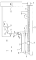
- FIG. 10 is a view showing an example of a production apparatus for producing the fourth embodiment of the catalyst structure according to the present invention.
- FIG. 11 is a partially enlarged view of the manufacturing apparatus shown in FIG.
- the base member 14 which comprises the catalyst structure 10E one end part (left-hand side edge part of FIG. 10) is obstruct
- the manufacturing apparatus 1 ⁇ / b> C has the hydrogen separator 16 (with the hydrogen permeable membrane 15 provided on the outer surface of the porous portion 14 a of the base member 14) in a state where the rotational symmetry axis 14 d of the base member 14 is aligned with the horizontal direction X. Is supported horizontally, and the catalyst support 12 is formed on the porous body 11 covered on the outer surface of the hydrogen separator 16.
- the manufacturing apparatus 1C for the catalyst structure 10E includes a pair of support members 150 and 152 as shown in FIG.
- the other end of the base member 14 is open, and the support member 150 has a tip that extends in the X direction and is finished in a shape that can be inserted into and removed from the hollow portion of the base member 14. Yes.
- the support member 152 employs a structure in which a plurality of claws hold and support the outer surface of the base member 14.
- the support members 150 and 152 are arranged with their tip portions opposed to each other on the same axis.
- (+ X) side support member 150 is rotatably arranged with respect to a fixed base 156 erected from the base 154.
- the ( ⁇ X) side support member 152 is disposed so as to be rotatable with respect to the movable base 160 that is movable in the X direction by the X direction moving mechanism 158.
- the X-direction moving mechanism 158 has a structure in which a ball screw 164 is connected to the motor 162, and a nut 166 fixed to the movable base 160 is attached to the ball screw 164.
- a guide rail 168 is fixed above the ball screw 164.
- the motor 162 rotates, the movable base 160 moves smoothly along the guide rail 168 in the X direction together with the nut 166.
- a motor 170 for rotationally driving the base member 14 about the rotational symmetry axis 14d is provided at the upper end of the movable base 160.
- a support member 152 is connected to the rotating shaft of the motor 170.
- the motor 162 is driven and controlled by the control unit 172 that controls each part of the manufacturing apparatus 1C in a state where the distal end portion of the support member 150 is inserted into the (+ X) side hollow end portion of the base member 14, thereby moving the movable base.
- the support member 152 moves in the (+ X) direction together with 160, and the distal end portion thereof is inserted into the ( ⁇ X) side hollow end portion of the base member 14.
- the hydrogen separation unit 16 is rotatably supported by the support members 150 and 152.
- the support members 150 and 152 function as the support portion 174 that supports the hydrogen separation portion 16. In this state, when the motor 170 is operated in accordance with a rotation command from the control unit 172, the hydrogen separation unit 16 can be rotated about the rotationally symmetric axis 14d as a rotation center.
- the head unit 176 is arranged at a position immediately above the hydrogen separation unit 16 supported by the support unit 174.
- the head unit 176 is attached to a frame (not shown) erected from the base 154 so as to be movable in the X direction, and the X direction moving mechanism 178 is operated in accordance with a movement command from the control unit 172. This moves in the X direction.
- the X-direction moving mechanism 178 may be configured in the same manner as the X-direction moving mechanism 158, or may be configured by another moving mechanism, for example, a linear moving mechanism using a linear motor as a drive source.
- a discharge nozzle portion 182 that discharges a fluid material prepared in advance and a heating portion 184 that irradiates and heats infrared rays toward the outer surface of the porous body 11 are provided on the lower surface of the base 180. It has been.
- a fluid material supply unit 186 is connected to the discharge nozzle unit 182. In response to a supply command from the control unit 172, the flowable material supply unit 186 pumps the flowable material containing the catalyst to the discharge nozzle unit 182 to discharge the flowable material from the discharge nozzle unit 182, and also controls the control unit 172. The flowable material discharge is stopped by a supply stop command from.
- the fluid material starts to remove the liquid component in the fluid material applied to the inside of the porous body 11 by being irradiated with infrared rays from the heating unit 184 described below.
- the manufacturing apparatus 1 ⁇ / b> C forms the supporting region 11 d as the catalyst supporting unit 12 on the hydrogen separation unit 16 and maintains the shape thereof.
- the heating unit 184 is connected to a light source unit 188 that generates infrared rays.
- the light source unit 188 is controlled by the control unit 172.
- a method for manufacturing the catalyst structure 10E using the manufacturing apparatus 1C described above will be described.
- a catalyst reference numeral 13 in FIG. 5
- a liquid component such as water or an organic solvent
- the fluid material (mixture) is stored in a tank (not shown) of the fluid material supply unit 186.
- the base member 14 is formed using the welding technique as described above, and the hydrogen permeable membrane 15 is provided on the outer surface of the porous portion 14 a of the base member 14 to prepare the hydrogen separation portion 16.
- the control unit 172 controls each part of the apparatus as follows in accordance with a program stored in a memory (not shown) in advance to form a support region 11d as the catalyst support unit 12 inside the porous body 11, Thus, the catalyst structure 10E is manufactured.
- a transfer device such as a transfer robot (not shown)
- the base member 14 is supported by the support members 150 and 152 in a horizontal posture.
- the head unit 176 stands by at a standby position away from the hydrogen separator 16 in the ( ⁇ X) direction.
- the rotation of the hydrogen separation unit 16 about the rotational symmetry axis 14d is started and the movement of the head unit 176 in the (+ X) direction is started.
- the discharge nozzle portion 182 has reached a position immediately above the starting point of the catalyst carrier 12, that is, a nozzle position (application start position) for starting application of the fluid material, the discharge nozzle portion 182 The discharge of the fluid material is started.
- the coating start position is located above the ( ⁇ X) side end of the hydrogen permeable membrane 15. ing.
- infrared irradiation from the heating unit 184 is started simultaneously with or slightly after the start of discharge of the fluid material.
- the fluid material is spirally applied to the inside of the porous body 11, and immediately after the application, the liquid component in the fluid material is removed by infrared irradiation, that is, the drying process starts, 11d is formed.
- the support region 11d formed in this way as shown in FIGS. 5 and 6, for example, a catalyst structure that partially supports the catalyst 13 inside the porous body 11 is obtained. 12 functions.
- the discharge nozzle unit 182 has reached the position directly above the end point (application end position) of the catalyst carrier 12
- the discharge of the fluid material from the discharge nozzle unit 182 is stopped.
- the infrared irradiation from the heating unit 184 is stopped.
- a desired spiral catalyst carrier 12 is applied to the porous body 11 to form the catalyst carrier 12 containing the catalyst, and the catalyst structure 10E is manufactured.
- the rotation of the hydrogen separation unit 16 and the movement of the head unit 176 are stopped, the support of the hydrogen separation unit 16 by the support unit 174 is released, and the catalyst structure 10E is carried out of the manufacturing apparatus 1C by the transport device, It is carried into another press unit (not shown).
- a back roller is inserted into the hollow interior of the catalyst structure 10E, and is held rotatably around the rotation axis of the back roller.
- the catalyst structure 10E also rotates integrally with the back roller.
- a press roller is provided on the surface of the catalyst structure 10E so as to be in contact with and separated from the surface.
- the press roller is configured to be rotatable about a rotation axis parallel to the rotation axis of the back roller, and is brought into contact with the catalyst structure 10E rotating the press roller with a constant pressing force by a separation / contact mechanism. Then, the outermost layer of the catalyst structure 10E, that is, the porous body 11 is pressed and rotated around the rotation axis. As a result, the porous body 11 is compressed in the thickness direction (pressing process), and the porous body 11 brings the catalyst 13 into close contact to a certain thickness. When this pressing step is completed, the catalyst structure 10E is unloaded from the press unit by the transport device.
- the catalyst 13 is partially supported inside the porous body 11 having a three-dimensional network structure, so that the support region 11f is not supported.
- a porous body 11 having a region 11g is formed.
- the reformed gas can be generated in the supporting region 11f while the raw material gas and the reformed gas are efficiently circulated through the non-supported region 11g, and the generation efficiency and the extraction efficiency of the reformed gas can be increased.
- the catalyst structure 10E according to the fourth embodiment has both the reforming function of the source gas and the purification function of the reformed gas, as in the third embodiment.
- the upper surface 11a and the lower surface 11b of the plate-like porous body 11 correspond to the “first main surface” and the “second main surface” of the present invention, respectively.
- the outer peripheral surface and the inner peripheral surface of the cylindrical porous body 11 correspond to the “first main surface” and the “second main surface” of the present invention, respectively.
- the stage 106 in the manufacturing apparatus 1A, the plurality of transport rollers 901 in the manufacturing apparatus 1B, and the support part 174 in the manufacturing apparatus 1C correspond to an example of the “holding part” of the present invention.
- the discharge nozzle part 130 in the manufacturing apparatus 1A, the discharge nozzle part 601 in the manufacturing apparatus 1B, and the discharge nozzle part 182 in the manufacturing apparatus 1C correspond to an example of the “catalyst carrying formation part” of the present invention. Furthermore, the flowable material corresponds to an example of the “preparation” of the present invention.
- the porous body 11 is forcibly heated after applying the flowable material to the porous body 11, that is, the drying step is performed.
- the liquid component may be removed from the substrate, and the naturally dried porous body 11 is used as a catalyst structure as it is, or a product obtained by subjecting the naturally dried porous body 11 to a pressing process is used as the catalyst structure. May be.
- the catalyst supporting part 12 is constituted by four supporting areas 11f, and in the fourth embodiment, the catalyst supporting part 12 is constituted by one spiral supporting area 11d.
- the number of the supporting regions 11d and 11f constituting the catalyst supporting unit 12 is not limited to this and is arbitrary.
- the supporting region 11f is formed in the X direction, and in the fourth embodiment, the supporting region 11d is formed in a spiral shape.
- the forming of the supporting regions 11d and 11f is performed. The direction and the form of formation are arbitrary.
- the shape of each of the supporting regions 11d and 11f is also arbitrary. In short, the same effect as that of the above-described embodiment can be obtained by partially forming the catalyst carrier 12 in the porous body 11 having a three-dimensional network structure.
- the present invention can be applied to a catalyst structure that reforms a raw material gas with a catalyst to generate a reformed gas, and a manufacturing technique of the catalyst structure.
Landscapes
- Chemical & Material Sciences (AREA)
- Organic Chemistry (AREA)
- Chemical Kinetics & Catalysis (AREA)
- Engineering & Computer Science (AREA)
- Materials Engineering (AREA)
- Combustion & Propulsion (AREA)
- Inorganic Chemistry (AREA)
- Health & Medical Sciences (AREA)
- General Health & Medical Sciences (AREA)
- Catalysts (AREA)
Abstract
触媒によって原料ガスを改質して改質ガスを生成する触媒構造体であって、互いに異なる第1主面および第2主面の間で原料ガスおよび改質ガスが流通可能な三次元網目構造を有する、多孔質体の内部で触媒を部分的に担持する。
Description
本発明は、触媒によって原料ガスを改質して改質ガスを生成する触媒構造体、および触媒構造体の製造技術に関するものである。
関連出願の相互参照
以下に示す日本出願の明細書、図面および特許請求の範囲における開示内容は、参照によりその全内容が本書に組み入れられる:
特願2015-25407(2015年2月12日出願)。
以下に示す日本出願の明細書、図面および特許請求の範囲における開示内容は、参照によりその全内容が本書に組み入れられる:
特願2015-25407(2015年2月12日出願)。
水素製造技術の一つとして、例えば特許文献1に記載されているように、メンブレンリアクタにより水素を製造するものが知られている。このメンブレンリアクタは、反応管(外管)内に水素分離管を配置した多重管構造を有している。反応管と水素分離管との間に粒状等の改質触媒が充填されて改質触媒層を形成している。この改質触媒層に対して炭化水素ガスを含む原料ガスが供給されると、原料ガスは改質触媒層により改質されて水素を含む改質ガスが生成される。そして、水素分離管に設けられるパラジウム(Pd)膜などの水素透過膜によって改質ガスから水素が分離される。こうして水素の精製が行われる。
上記したメンブレンリアクタでは、改質触媒が反応管と水素分離管との間に充填されていることから、水素分離管に設けられた水素透過膜の全面に対して改質触媒が接触している。このため、改質触媒層の改質触媒により生成された改質ガスを改質触媒層から効率良く流通させることが難しく、このことが、水素透過膜を介して水素が水素分離管の内部に分離される割合、つまり精製効率を低下させる主要因のひとつとなっている。このような問題は、多重管構造のみならず、平板型構造を採用した場合にも同様である。
本発明は上記課題に鑑みなされたものであり、触媒への原料ガスの供給および改質ガスの取り出しを効率的に行って改質処理の効率を高めることができる触媒構造体、ならびに当該触媒構造体を製造する製造技術を提供することを目的とする。
本発明の第1態様は、触媒によって原料ガスを改質して改質ガスを生成する触媒構造体であって、互いに異なる第1主面および第2主面の間で原料ガスおよび改質ガスが流通可能な三次元網目構造を有する、多孔質体の内部で触媒を部分的に担持することを特徴としている。
また、本発明の第2態様は、触媒によって原料ガスを改質して改質ガスを生成する、触媒構造体の製造方法であって、互いに異なる第1主面および第2主面の間で原料ガスおよび改質ガスが流通可能な三次元網目構造を有する、多孔質体に対して第1主面側から触媒を含む流動性材料を供給して多孔質体の内部で触媒を部分的に担持させる第1工程を備えることを特徴としている。
さらに、本発明の第3態様は、触媒によって原料ガスを改質して改質ガスを生成する、触媒構造体の製造装置であって、互いに異なる第1主面および第2主面の間で原料ガスおよび改質ガスが流通可能な三次元網目構造を有する、多孔質体を第1主面を上方に向けて保持する保持部と、保持部に保持された多孔質体の第1主面に触媒を含む流動性材料を供給して触媒を担持する触媒担持部を多孔質体の内部に部分的に形成する触媒担持形成部とを備えることを特徴としている。
本発明によれば、触媒が多孔質体の内部で部分的に担持されている。このため、多孔質体の内部では、触媒を担持する担持領域と、触媒を担持しない非担持領域とが設けられる。これらのうち担持領域では触媒による改質処理が行われる。一方、非担持領域では、三次元網目構造が維持されて原料ガスや改質ガスを流通可能となっている。このため、担持領域への原料ガスの供給および改質ガスの取り出しが非担持領域を通じて実行され、その結果、改質ガスを効率的に生成することができる。
上述した本発明の各態様の有する複数の構成要素はすべてが必須のものではなく、上述の課題の一部又は全部を解決するため、あるいは、本明細書に記載された効果の一部又は全部を達成するために、適宜、前記複数の構成要素の一部の構成要素について、その変更、削除、新たな他の構成要素との差し替え、限定内容の一部削除を行うことが可能である。また、上述の課題の一部又は全部を解決するため、あるいは、本明細書に記載された効果の一部又は全部を達成するために、上述した本発明の一態様に含まれる技術的特徴の一部又は全部を上述した本発明の他の態様に含まれる技術的特徴の一部又は全部と組み合わせて、本発明の独立した一形態とすることも可能である。
図1は本発明にかかる触媒構造体の第1実施形態を示す斜視図である。同図中の破線部分は部分断面の拡大図である。触媒構造体10Aは、平板状あるいはシート状の多孔質体11と、多孔質体11の内部において触媒を部分的に担持する触媒担持部12とを備えている。
多孔質体11は触媒活性のない材料で形成されている。多孔質体11の内部においては、三次元網目構造が形成され、上面11aおよび下面11bの間で原料ガスおよび改質ガスが流通可能となっている。ここで、「三次元網目構造」とは、多数の空孔部(図1中の符号11c参照)が三次元的に配設されて粗大で独立した空孔部を実質的に有しない網目状の構造を意味している。本実施形態では、多孔質体11として発泡金属、特に使用環境を考慮してSUS304、SUS316、SUS316L等のステンレス発泡金属を用いているが、触媒活性を有しない材料で構成された多孔質体であれば、特に限定されるものではない。
また、本実施形態では、次に説明する製造装置1Aにより触媒を担持する担持領域11fが複数の空孔部の一部に形成され、担持領域11fによってX方向に延びるライン状、帯状あるいは棒状の触媒担持部12が多孔質体11の内部に形成されている。なお、本実施形態では、図1に示すように4本の触媒担持部12がY方向に互いに離間しながら配列されているが、形状、本数や配列などについては任意である。以下、触媒構造体10Aを製造する製造装置1Aおよび当該装置1Aによる製造手順を図2ないし図5を参照しつつ説明し、触媒構造体10Aの特徴についても併せて明らかにする。
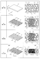
図2は図1の触媒構造体を製造する製造装置の概略構成を示す図である。また、図3は図2の製造装置に含まれる塗布ユニットの構成を示す図である。また、図4は図3の塗布ユニットに装備されるヘッド部の構成をより詳細に示す拡大図である。さらに、図5は図2の装置による触媒構造体の製造方法を説明するための模式図である。触媒構造体10Aを製造する製造装置1Aは、塗布ユニット100と、乾燥ユニット200と、プレスユニット300と、4台の搬送ユニット400a~400dと、制御ユニット500とを備えている。そして、予め設定されたプログラムにしたがって制御ユニット500が装置各部を制御することで多孔質体11を搬送ユニット400a~400dによって塗布ユニット100、乾燥ユニット200およびプレスユニット300の順で搬送しながら塗布処理、乾燥処理およびプレス処理を行い、それによって図1に示す触媒構造体10Aが製造される。なお、乾燥ユニット200、プレスユニット300、搬送ユニット400a~400dおよび制御ユニット500の構成は周知であるため、図示説明を省略する。
塗布ユニット100は、多孔質体11に対し、触媒を含有する流動性材料を塗布することで多孔質体11の内部に浸透させて触媒を部分的に担持させるためのユニットである。この塗布ユニット100では、図3に示すように、基台102上にステージ移動機構104が設けられ、多孔質体11を保持するステージ106がステージ移動機構104によりX-Y平面内で移動可能となっている。基台102にはステージ106を跨ぐようにしてフレーム108が固定され、フレーム108にはヘッド部110が取り付けられる。
ステージ移動機構104は、下段からステージ106をX方向に移動させるX方向移動機構112およびY方向に移動させるY方向移動機構114を有する。X方向移動機構112は、モータ116にボールねじ118が接続され、さらに、Y方向移動機構114に固定されたナット120がボールねじ118に取り付けられた構造となっている。ボールねじ118の上方にはガイドレール122が固定され、モータ116が回転すると、ナット120とともにY方向移動機構114がガイドレール122に沿ってX方向に滑らかに移動する。
Y方向移動機構114もモータ124、ボールねじ機構(図示省略)およびガイドレール126を有し、モータ124が回転するとボールねじ機構によりステージ106がガイドレール126に沿ってY方向に移動する。以上の構成により、ヘッド部110の多孔質体11に対する相対的な移動方向が変更可能とされる。ステージ移動機構104の各モータは装置全体を制御する制御ユニット500により制御される。なお、塗布ユニット100を制御するための専用の制御部を設け、制御ユニット500からの指令に応じて当該制御部が塗布ユニット100の各部を制御するように構成してもよい。
ヘッド部110では、ベース128の下面に対し、予め調製された流動性材料を吐出する吐出ノズル部130が設けられている。また、吐出ノズル部130には供給管132が取り付けられる。供給管132は、制御弁134、ポンプ136および流量計138を介して触媒を含む流動性材料を貯留するタンク140に接続される。そして、制御ユニット500がポンプ136を駆動するとともに制御弁134の開閉を制御することにより、吐出ノズル部130からの流動性材料吐出のオン・オフが制御される。
図4はヘッド部の構成をより詳細に示す拡大図であり、ヘッド部110を下方から見たときの吐出ノズル部130先端付近を示す図である。吐出ノズル部130は内部が筒状の空洞になったノズルベース142に、この空洞に連通された吐出口144を有する筒状の先端ノズル146が複数個(この例では4個であるがこれに限定されない)、Y方向に等間隔に突設された構造となっている。タンク140から供給管132を経由して輸送されてくる流動性材料は、先端ノズル146下端の吐出口144から多孔質体11の上面11aに向けて吐出される。図3および図4に示すように、先端ノズル146は、ノズルベース142から(-Z)方向および(+X)方向に延びている。
先端ノズル146の材質については特に限定されないが、吐出口144から吐出される流動性材料に対し汚染物質を混入させることがなく、微細加工ができるという点から、例えばシリコンやジルコニアの結晶を用いることができる。ただし、ヘッド部110に設けられた複数の先端ノズル146はいずれも同一形状とされる。このような微細な加工を要する先端ノズルの形状を全て同一とすることにより、先端ノズルの加工コスト、ひいては装置全体のコストを低減することができる。また、それぞれ1つの吐出口を有し同一形状の複数の先端ノズルをノズルベースに着脱可能に取り付けるようにすれば、例えばいずれかの吐出口が流動性材料によって目詰まりや損傷を起こした場合、当該先端ノズルのみを交換すればよいので、吐出ノズル部全体を交換するのに比べれば装置のランニングコストの点でも有利である。
なお、本実施形態では、次に詳述するように多孔質体11の内部に触媒担持部12を形成するために、多孔質体11に形成されている空孔部11cの平均孔径よりも小さい粒径を有する触媒(図5中の符号13)を用いている。より具体的には、粒径1ないし100[μm]の粉末状のシリカ(SiO2)、アルミナ(Al2O3)、酸化チタン(TiO2)などを触媒担体として用いている。また、触媒13によって触媒機能を発揮させるために、本実施形態では、触媒担体よりも小径の金(Au)、白金(Pt)、パラジウム(Pd)などの単体元素、それらの酸化物あるいは水酸化物を触媒粒子として用いている。
次に、図2の製造装置1Aにより触媒構造体10Aを製造する方法について図5を参照しつつ説明する。この第1実施形態では、触媒13と水や有機溶剤などの液体成分とを混合してペースト状の流動性材料を調製しておき、当該流動性材料をタンク140(図3)に貯留しておく。
触媒構造体10Aの製造準備が完了すると、塗布ユニット100内に搬送ロボット400aが多孔質体11を搬入し、図5中の(a)欄に示すように、一方主面11aを鉛直方向の上方(+Z)に向けた状態でステージ106に載置する(搬入工程)。そして、多孔質体11はステージ106で保持される。この多孔質体11は三次元網目構造を有しており、多孔質体11の内部に複数の空孔部11cが設けられている。また、この段階での多孔質体11の厚みT1、つまり鉛直方向Zにおける上面11aおよび下面11bの間隔は比較的厚く設定されている。また、本実施形態では、空隙率が50%以上の多孔質体11を用いている。
次に、塗布ユニット100による流動性材料の多孔質体11への塗布が実行される(塗布工程)。この塗布工程では、ステージ移動機構104が動作して、多孔質体11をその右端がヘッド部110の直下近傍位置に来るような所定の塗布開始位置(図3における多孔質体11の位置)へ移動させる。次いで、多孔質体11をX方向に移動させながら、ヘッド部110に設けた吐出ノズル部130からの流動性材料吐出が開始される。先端ノズル142から流動性材料が連続的かつ棒状に吐出され、図5中の(b)欄に示すように吐出口144のY方向幅、つまりライン幅Wで多孔質体11の上面11aに供給される。すると、流動性材料はライン幅Wに含まれる多孔質体11に流通して下面11bに向かって広がっていく。なお、この点を明確にするために、図5の(b)欄においては流動性材料を含有する空孔部11cに対して比較的細かいピッチでドットを施している。これについては後で説明する図6においても同様である。
また、多孔質体11の内部のうち上記のようにして流動性材料の供給を受けて触媒を担持する領域、つまり担持領域11dは多孔質体11のX方向移動に伴ってX方向に延設され、互いに平行な複数本(この例では4本)の帯状で流動性材料が塗布されていく。なお、ここでは、多孔質体11の内部のうち流動性材料を受けず流動性材料が浸透していない領域11eを「非担持領域」と称する。
多孔質体11の一方端から他方端まで流動性材料の塗布(塗布工程)が終了すると、多孔質体11の全面に帯状の担持領域11dを形成し終えるまで、塗布開始位置に戻って上記動作を必要回数繰り返し行う。このとき、1回の動作を終えるごとに多孔質体11の位置をY方向に所定量移動させることで、吐出口144の数よりも多い本数の担持領域11dを形成することができる。こうして所望本数の帯状担持領域11dがY方向に一定間隔で多孔質体11の内部に形成されると、搬送ロボット400bが当該多孔質体11を塗布ユニット100から乾燥ユニット200に搬送する。
この乾燥ユニット200では、多孔質体11に熱が加えられ、流動性材料に含まれる液体成分が取り除かれる(乾燥工程)。これにより、多孔質体11の内部で触媒13を担持する触媒担持部12を部分的に有する触媒構造体が得られ、これを最終製品としてもよいが、図5中の(c)欄において模式的に示すように、液体成分の除去によって各空孔部11cでは触媒13の周囲に比較的大きな空隙が形成される。このため、触媒13は安定して多孔質体11に担持されていると必ずしも言えず、多孔質体11からの脱落を招く可能性がある。そこで、本実施形態では、乾燥工程が完了すると、搬送ロボット400cが当該多孔質体11を乾燥ユニット200からプレスユニット300に搬送する。
このプレスユニット300では、多孔質体11の上面11aおよび下面11bにそれぞれ(-Z)方向および(+Z)方向の応力を与えて上面11aと下面11bとの距離、つまり多孔質体11の厚みがT2(<T1)まで減少するように多孔質体11を圧縮する。これによって、多孔質体11の空隙率が10~40%になり、担持領域11d内の空孔部11cが触媒13に密接し、また空孔部11cに含まれる複数の触媒13も互い密接して触媒13は多孔質体11に強固に固定される。こうして、触媒13を多孔質体11にしっかりと担持した担持領域11fがライン状あるいは帯状にX方向に延設され、これら4本の担持領域11fが触媒担持部12となる。一方、互いに隣り合う担持領域11fの間には、触媒13を担持しない非担持領域11gが形成されており、当該非担持領域11gに含まれる空孔部11cが原料ガスや改質ガスを流通させる流路として機能する。
上記した塗布工程、乾燥工程およびプレス工程を経て図1に示す触媒構造体10Aが製造されると、搬送ロボット400dはプレスユニット300から触媒構造体10A(=多孔質体11+触媒担持部12)を搬出し、触媒構造体10Aを種々の装置、例えば改質ガスを製造するための改質触媒として改質装置の反応容器に収容する。
以上のように、第1実施形態では、三次元網目構造を有する多孔質体11の一部に流動性材料が帯状に塗布されて触媒13が多孔質体11の内部で部分的に担持される。これによって、図1や図5に示すように、担持領域11fと非担持領域11gとをY方向に交互に並設したラインアンドスペース構造が多孔質体11に形成される。担持領域11fには触媒13が担持されて触媒担持部12として機能する。一方、非担持領域11gでは三次元網目構造がそのまま維持されて原料ガスおよび改質ガスの流通経路となる。したがって、多孔質体11の上面11aや下面11bを介して供給される原料ガスは非担持領域11gを介して担持領域11f(触媒担持部12)に供給されて触媒13によって改質される。担持領域11fで生成された水素を含む改質ガスは非担持領域11gを流通して多孔質体11の上面11aや下面11bから取り出される。よって、このように非担持領域11gを利用して原料ガスおよび改質ガスを効率的に流通することができ、改質ガスを効率的に生成し、取り出すことが可能となっている。
また、上記第1実施形態では、多孔質体11の内部に形成される空孔部11cに触媒13を担持させているため、改質処理中に触媒13が脱落するのを防止することができる。しかも、単に担持させるだけでなく、図5の(d)欄に示すように、プレス工程によって多孔質体11を厚み方向Zにおいて圧縮して触媒13を密接させている。このため、触媒13の脱落をさらに効果的に防止することができ、より安定した改質処理を行うことができる。
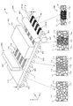
図6は本発明にかかる触媒構造体の製造装置の他の実施形態を示す斜視図である。この製造装置1Bが上記製造装置1Aと大きく相違する点は、一つの装置(ユニット)内で塗布工程、乾燥工程およびプレス工程が連続的に行われている点であり、塗布工程、乾燥工程およびプレス工程が第1実施形態と同様にして行われる。なお、同図中の最下段に示す模式図は、それぞれ塗布工程前、塗布工程と乾燥工程の間、乾燥工程とプレス工程の間、およびプレス工程後における多孔質体11の内部を模式的に示す図である。
この触媒構造体の製造装置1Bは、図6に示すように、塗布工程を行う塗布部600、乾燥工程を行う乾燥部700、プレス工程を行うローラプレス部800、およびシート状の多孔質体11を搬送する搬送部900を備えている。この搬送部900は、X方向に配列した複数の搬送ローラ901を有しており、装置全体を制御する制御部(図示省略)からの搬送指令にしたがって搬送ローラ901を回転駆動することで多孔質体11を略水平姿勢のままX方向に搬送する。また、多孔質体11の搬送経路に沿って、搬送部900の上方位置に塗布部600、乾燥部700およびローラプレス部800がこの順序で配置されている。
塗布部600は、塗布ユニット100と同様に複数(本実施形態においても4個)の吐出口を有する吐出ノズル部601を有している。この吐出ノズル部601は図示を省略する流動性材料供給部から触媒を含有する流動性材料の供給を受けて各吐出口から流動性材料を複数の搬送ローラ901で支持されながらX方向に搬送されるシート状多孔質体11の上面11aに吐出する。これによって、多孔質体11への流動性材料の塗布が行われ(塗布工程)、多孔質体11の一部では空孔部11c内に流動性材料が浸透し、X方向に延びる担持領域11dが多孔質体11の内部に形成される。
乾燥部700は、上記塗布部600からローラ搬送されてくる多孔質体11を加熱する加熱機構701を有している。この加熱機構701による加熱によって流動性材料に含まれる液体成分が取り除かれる(乾燥工程)。
ローラプレス部800は、図6に示すように、多孔質体11の初期厚みT1よりも狭い間隔T2だけ上下方向Zに離間して配置される一対のプレスローラ801、801と、これらのプレスローラ801、801を回転駆動する駆動機構(図示省略)とを有している。そして、制御部からの回転指令に応じて駆動機構が作動することでプレスローラ801、801が回転駆動される。乾燥工程を経てローラプレス部800に多孔質体11がローラ搬送されてくると、プレスローラ801、801の間を通過する際に、多孔質体11は厚みT1から厚みT2に上下方向Zに圧縮される(プレス工程)。これによって、第1実施形態と同様に、触媒13を多孔質体11にしっかりと担持した担持領域11fがライン状あるいは帯状にX方向に延設され、これら4本の担持領域11fによって触媒担持部12が構成された触媒構造体10Bが製造される。もちろん、互いに隣り合う担持領域11fの間には、触媒13を担持しない非担持領域11gが形成されており、当該非担持領域11gに含まれる空孔部11cが原料ガスや改質ガスを流通させる流路として機能する。
以上のように、第2実施形態においても、第1実施形態と同様に構成され、同様の作用効果を奏する。すなわち、三次元網目構造を有する多孔質体11の内部において触媒13を部分的に担持させることで担持領域11fと非担持領域11gとをY方向に交互に並設したラインアンドスペース構造が多孔質体11に形成される。このため、非担持領域11gによって原料ガスおよび改質ガスを効率的に流通させながら担持領域11fで改質ガスを生成することができ、改質ガスの生成効率および取出効率を高めることができる。また、空孔部11cでの触媒13の担持およびプレス工程による触媒13の密接を行っているため、触媒13の脱落を効果的に防止して改質処理をより安定的に行うことが可能となっている。
しかも、第2実施形態では、多孔質体11をX方向にローラ搬送しながら塗布工程、乾燥工程およびプレス工程を並行して行うことができ、生産性を高めることができる。また、X方向に延設される長尺の多孔質体11をロール状に巻き取った多孔質体ロール(図示省略)を準備しておき、多孔質体ロールから多孔質体11を繰り出し、上記製造装置1Bで触媒構造体を連続的に製造してもよい。こうして製造されるシート状の触媒構造体についてロール状に巻き取ってもよいし、所定の長さで切り離して図1に示すような平板状あるいはシート状の触媒構造体10Aを製造してもよい。
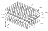
図7は本発明にかかる触媒構造体の第2実施形態を示す図である。同図では、触媒構造体10Cの主要構成が上下方向Zに分解して図示されているが、実際の製品は上下方向Zにおいて積層され、一体化されている。この触媒構造体10Cが第1実施形態と大きく相違する点は、補強部材17a、17bがそれぞれ多孔質体11の上面11a、11bに密着される点であり、その他の構成は同一である。補強部材17a、17bは、触媒活性を有しない材料で構成され、プレス工程を受けてZ方向に圧縮された多孔質体11よりも高い剛性を有している。また、補強部材17a、17bには、複数の貫通孔171が形成されており、原料ガスおよび改質ガスを流通自在となっている。このため、原料ガスおよび改質ガスの流通性を損なうことなく、補強部材17a、17bにより多孔質体11を挟み込むことで触媒構造体10Bの強度を高めることができ、改質処理の安定性をさらに高めることができる。このように本実施形態では、補強部材17a、17bがそれぞれ本発明の「第1補強部材」および「第2補強部材」に相当している。さらに、補強部材17aを多孔質体11の上面11aに密着させる工程および補強部材17bを多孔質体11の下面11bに密着させる工程がそれぞれ本発明の「第4工程」および「第5工程」に相当している。
図8は本発明にかかる触媒構造体の第3実施形態を示す図である。同図では、触媒構造体10Dの主要構成が上下方向Zに分解して図示されているが、実際の製品は上下方向Zにおいて積層され、一体化されている。この触媒構造体10Dが第1実施形態と大きく相違する点は、多孔質体11の上面11aに対して補強部材17aが密着されるとともに、多孔質体11の下面11bに対して水素分離部16が密着されている。この水素分離部16は、触媒活性のない材料で形成された三次元網目構造を有する多孔質部で全体が構成される平板状のベース部材14と、ベース部材14に対してPdなどの水素透過材料で形成される水素透過膜15とを有している。
このように構成された第3実施形態では、補強部材17aの貫通孔171を介して原料ガスが多孔質体11の上面11aに供給され、さらに非担持領域11gを流通して担持領域11fの触媒に与えて改質処理を行っている。また、改質処理により生成された改質ガス中の水素は水素分離部16を介して触媒構造体10Cから取り出される。したがって、第2実施形態と同様に補強部材17aと水素透過膜15とで触媒構造体10Bの強度を高めた上で水素を効率的に精製することができる。すなわち、第3実施形態にかかる触媒構造体10Cは原料ガスの改質機能と、改質ガスの精製機能とを兼ね備えている。なお、本実施形態では、補強部材17aを多孔質体11の上面11aに密着させる工程および水素分離部16を多孔質体11の下面11bに密着させる工程がそれぞれ本発明の「第4工程」および「第6工程」に相当している。
ところで、上記実施形態では、平板状あるいはシート状の多孔質体11の内部に触媒13を部分的に担持させて触媒担持部12を形成しているが、多孔質体11の形状はこれに限定されるものではなく、任意である。例えば、図9に示すように円筒形状の多孔質体11を用いる触媒構造体10Eに対して本発明を適用することができる。もちろん、円筒形状の代わりに角筒形状の多孔質体を用いてもよい。以下、図9ないし図11を参照しつつ本発明の第4実施形態について説明する。
図9は本発明にかかる触媒構造体の第4実施形態を示す図である。この触媒構造体10Eは、X方向に延びる筒状のベース部材14と、Pdなどの水素透過材料で形成される水素透過膜15と、多孔質体11と、触媒担持部12とを有している。ベース部材14はX方向に延びる中空の円筒形状を有している。このベース部材14の中央部は多孔質ステンレス管や多孔質セラミックス管などで構成される多孔質部14aである。一方、ベース部材14の(-X)側端部14bおよび(+X)側端部14cはいずれも通常のステンレス管などの非多孔質管で構成されている。例えば多孔質ステンレスの両端部に非多孔質ステンレス管をそれぞれ連結し、各連結部を溶接することでベース部材14が得られる。なお、(-X)側端部14bの側方は通常のステンレス板などの非多孔質部材が溶接されて閉塞されており、次に説明するようにしてベース部材14の中空部に透過してくる水素を(+X)側端から取り出し可能となっている。
このベース部材14の多孔質部14aの外面に水素透過膜15が設けられている。このため、触媒担持部12の触媒により生成される改質ガスのうち水素のみが水素透過膜15および多孔質部14aを介してベース部材14の中空部に透過、より具体的には溶解拡散可能となっており、水素透過膜15中では、水素イオンの形態で存在している。一方、水素を除く改質ガスおよび原料ガスは水素透過膜15で阻止され、多孔質部14aを介してベース部材14の中空部に溶解拡散するのが防止される。
水素透過膜15の外面に設けられる多孔質体11の内部では、図9に示すように、触媒担持部12として機能する担持領域11dが螺旋状に形成されており、担持領域11d以外の領域が非担持領域11eとなっている。このような構成を有する触媒構造体10Eを次に説明する製造装置1Cを用いて製造している。
図10は本発明にかかる触媒構造体の第4実施形態を製造するための製造装置の一例を示す図である。また、図11は図10に示す製造装置の部分拡大図である。ここでは、触媒構造体10Eを構成するベース部材14は、一方端部(図10の左手側端部)が閉塞されるとともに他方端部(図10の右手側端部)が開口しており、全体として円筒形状を有している。そして、製造装置1Cは、ベース部材14の回転対称軸14dを水平方向Xに一致させた状態で水素分離部16(ベース部材14の多孔質部14aの外面に水素透過膜15を設けたもの)を水平支持し、当該水素分離部16の外面に被覆される多孔質体11への触媒担持部12の形成を行う。
触媒構造体10Eの製造装置1Cは、図10に示すように、一対の支持部材150、152を有している。本実施形態では、ベース部材14の他方端部が開口しているのに対応し、支持部材150についてはX方向に延びる先端部がベース部材14の中空部に挿脱自在な形状に仕上げられている。一方、ベース部材14の一方端部が閉塞しているのに対応し、支持部材152については複数の爪がベース部材14の外側面を把持して支持する構造を採用している。そして、支持部材150、152は互いに先端部を同一軸線上で対向させた状態で配置されている。これらのうち(+X)側の支持部材150は基台154から立設される固定ベース156に対して回転自在に配置されている。一方、(-X)側の支持部材152はX方向移動機構158によりX方向に移動自在な可動ベース160に対して回転自在に配置されている。
このX方向移動機構158では、モータ162にボールねじ164が接続され、さらに、可動ベース160に固定されたナット166がボールねじ164に取り付けられた構造となっている。ボールねじ164の上方にはガイドレール168が固定され、モータ162が回転すると、ナット166とともに可動ベース160がガイドレール168に沿ってX方向に滑らかに移動する。この可動ベース160の上端部には、回転対称軸14dを回転中心としてベース部材14を回転駆動するためのモータ170が設けられている。このモータ170の回転軸に支持部材152が連結されている。このため、ベース部材14の(+X)側の中空端部に支持部材150の先端部を挿入した状態で製造装置1Cの各部を制御する制御部172によりモータ162を駆動制御することで、可動ベース160とともに支持部材152が(+X)方向に移動し、その先端部がベース部材14の(-X)側の中空端部に挿入される。これによって、水素分離部16が支持部材150、152によって回転自在に支持される。このように支持部材150、152が水素分離部16を支持する支持部174として機能する。また、この状態で制御部172からの回転指令に応じてモータ170が作動すると、回転対称軸14dを回転中心として水素分離部16を回転させることができる。
また、図10に示すように、支持部174により支持される水素分離部16の直上位置でヘッドユニット176が配置されている。このヘッドユニット176は、基台154から立設されたフレーム(図示省略)に対してX方向に移動自在に取り付けられるとともに、制御部172からの移動指令に応じてX方向移動機構178が作動することでX方向に移動される。なお、X方向移動機構178は、X方向移動機構158と同様に構成してもよいし、別の移動機構、例えばリニアモータを駆動源とする直線移動機構で構成してもよい。
ヘッドユニット176では、ベース180の下面に対し、予め調製された流動性材料を吐出する吐出ノズル部182と、多孔質体11の外面に向けて赤外線を照射して加熱する加熱部184とが設けられている。また、吐出ノズル部182には流動性材料供給部186が接続されている。この流動性材料供給部186は、制御部172からの供給指令に応じて触媒を含む流動性材料を吐出ノズル部182に圧送して吐出ノズル部182から流動性材料を吐出させ、また制御部172からの供給停止指令により流動性材料吐出を停止させる。また、流動性材料は、次に説明する加熱部184からの赤外線照射を受けて多孔質体11の内部に塗布された流動性材料中の液体成分の除去が始まる。このようにして、この製造装置1Cは水素分離部16上に担持領域11dを触媒担持部12として形成し、その形状を維持させる。
加熱部184は赤外線を発生する光源ユニット188に接続される。光源ユニット188は制御部172により制御される。
次に、前述した製造装置1Cにより、触媒構造体10Eを製造する方法について説明する。製造装置1Cによる触媒構造体10Eの製造に先立って、予め触媒(図5中の符号13)と、水や有機溶剤などの液体成分とを混合してペースト状の流動性材料を調製し、当該流動性材料(混合物)を流動性材料供給部186のタンク(図示省略)の貯留しておく。また、上記のように溶接技術を用いてベース部材14を形成するとともに、当該ベース部材14の多孔質部14aの外面に水素透過膜15を設けて水素分離部16を準備しておく。
そして、制御部172は予めメモリ(図示省略)に記憶されているプログラムにしたがって装置各部を以下のように制御して多孔質体11の内部に担持領域11dを触媒担持部12として形成し、これによって触媒構造体10Eを製造する。まず、図示を省略する搬送ロボットなどの搬送装置により水素分離部16が製造装置1Cに搬入されると、ベース部材14を支持部材150、152で水素分離部16を水平姿勢で支持する。このとき、ヘッドユニット176は水素分離部16から(-X)方向に離れた待機位置に待機している。
水素分離部16の支持が完了すると、回転対称軸14dを回転中心とする水素分離部16の回転を開始するとともに、ヘッドユニット176の(+X)方向への移動を開始する。そして、吐出ノズル部182が触媒担持部12の始点の直上位置、つまり流動性材料の塗布を開始するためのノズル位置(塗布開始位置)に到達したことが確認されると、吐出ノズル部182からの流動性材料の吐出を開始する。なお、この実施形態では、水素透過膜15の(-X)側端部より触媒担持部12を形成するため、塗布開始位置は水素透過膜15の(-X)側端部の上方位置となっている。
また、流動性材料の吐出開始と同時あるいは若干遅れて加熱部184からの赤外線照射を開始する。これによって、多孔質体11の内部には、流動性材料が螺旋状に塗布され、その塗布後、ただちに赤外線照射を受けて流動性材料中の液体成分の除去、つまり乾燥工程が始まり、担持領域11dが形成される。こうして形成された担持領域11dでは、例えば図5や図6に示すように、多孔質体11の内部で触媒13を部分的に担持する触媒構造体が得られ、当該担持領域11dが触媒担持部12として機能する。
そして、吐出ノズル部182が触媒担持部12の終点の直上位置(塗布終了位置)に到達したことが確認されると、吐出ノズル部182からの流動性材料の吐出を停止する。また、これから一定時間(触媒担持部12の終端が加熱部184の直下位置を通過するまでの時間)後に、加熱部184からの赤外線照射を停止する。これによって、多孔質体11に所望の螺旋状の触媒担持部12が塗布されて触媒を含む触媒担持部12が形成され、触媒構造体10Eが製造される。
それに続いて、水素分離部16の回転およびヘッドユニット176の移動を停止させ、さらに支持部174による水素分離部16の支持を解除し、搬送装置により触媒構造体10Eが製造装置1Cから搬出され、別のプレスユニット(図示省略)に搬入される。このプレスユニットでは、触媒構造体10Eの中空内部にバックローラが挿入されて当該バックローラの回転軸まわりに回転自在に保持される。そして、回転駆動機構によってバックローラが回転駆動されると、バックローラと一体的に触媒構造体10Eも回転する。この触媒構造体10Eの表面に対し、プレスローラが当接および離間自在に設けられている。このプレスローラはバックローラの回転軸と平行な回転軸まわりに回転自在に構成されており、離当接機構によってプレスローラが回転している触媒構造体10Eに一定の押圧力で当接する。そして、触媒構造体10Eの最表層、つまり多孔質体11をプレスしながら上記回転軸まわりに従動回転する。これによって、多孔質体11は厚さ方向に圧縮され(プレス工程)、多孔質体11が一定厚さまで触媒13を密接させている。このプレス工程が完了すると、搬送装置によりプレスユニットから触媒構造体10Eが搬出される。
以上のように、第4実施形態においても、第1実施形態などと同様に、三次元網目構造を有する多孔質体11の内部において触媒13を部分的に担持させることで担持領域11fと非担持領域11gとを有する多孔質体11が形成される。このため、非担持領域11gによって原料ガスおよび改質ガスを効率的に流通させながら担持領域11fで改質ガスを生成することができ、改質ガスの生成効率および取出効率を高めることができる。また、第4実施形態にかかる触媒構造体10Eは、第3実施形態と同様に、原料ガスの改質機能と、改質ガスの精製機能とを兼ね備えている。
上記した第1実施形態ないし第3実施形態では平板状の多孔質体11の上面11aおよび下面11bがそれぞれ本発明の「第1主面」および「第2主面」に相当し、第4実施形態では筒状の多孔質体11の外周面および内周面がそれぞれ本発明の「第1主面」および「第2主面」に相当している。また、製造装置1A中のステージ106、製造装置1B中の複数の搬送ローラ901および製造装置1C中の支持部174が本発明の「保持部」の一例に相当している。製造装置1A中の吐出ノズル部130、製造装置1B中の吐出ノズル部601および製造装置1C中の吐出ノズル部182が本発明の「触媒担持形成部」の一例に相当している。さらに、流動性材料が本発明の「調製物」の一例に相当している。
なお、本発明は上記した実施形態に限定されるものではなく、その趣旨を逸脱しない限りにおいて上述したもの以外に種々の変更を行うことが可能である。例えば、上記実施形態では、多孔質体11に流動性材料を塗布した後で多孔質体11を強制的に加熱している、つまり乾燥工程を実行しているが、自然乾燥によって空孔部11cから液体成分を除去してもよく、自然乾燥された多孔質体11をそのまま触媒構造体として用いたり、自然乾燥された多孔質体11に対してプレス工程を施したものを触媒構造体として用いてもよい。
また、上記第1実施形態ないし第3実施形態では4本の担持領域11fにより触媒担持部12を構成し、上記第4実施形態では1本の螺旋状の担持領域11dにより触媒担持部12を構成しているが、触媒担持部12を構成する担持領域11d、11fの本数はこれに限定されるものではなく、任意である。また、上記第1実施形態ないし第3実施形態では担持領域11fをX方向に形成し、上記第4実施形態では担持領域11dを螺旋状に形成しているが、各担持領域11d、11fの形成方向や形成態様は任意である。さらに、各担持領域11d、11fの形状についても任意である。要は、三次元網目構造を有する多孔質体11の内部において触媒担持部12を部分的に形成することで上記実施形態と同様の作用効果が得られる。
以上、特定の実施例に沿って発明を説明したが、この説明は限定的な意味で解釈されることを意図したものではない。発明の説明を参照すれば、本発明のその他の実施形態と同様に、開示された実施形態の様々な変形例が、この技術に精通した者に明らかとなるであろう。故に、添付の特許請求の範囲は、発明の真の範囲を逸脱しない範囲内で、当該変形例または実施形態を含むものと考えられる。
この発明は、触媒によって原料ガスを改質して改質ガスを生成する触媒構造体、および触媒構造体の製造技術について適用することができる。
1A,1B,1C…(触媒構造体の)製造装置
10A,10B,10C,10D,10E…触媒構造体
11…多孔質体
11a…上面(第1主面)
11b…下面(第2主面)
11c…空孔部
11d、11f…担持領域
11e,11g…非担持領域
12…触媒担持部
13…触媒
16…水素分離部
17a…(第1)補強部材
17b…(第2)補強部材
106…ステージ(保持部)
130、182、601…吐出ノズル部(触媒担持形成部)
174…支持部(保持部)
901…搬送ローラ(保持部)
10A,10B,10C,10D,10E…触媒構造体
11…多孔質体
11a…上面(第1主面)
11b…下面(第2主面)
11c…空孔部
11d、11f…担持領域
11e,11g…非担持領域
12…触媒担持部
13…触媒
16…水素分離部
17a…(第1)補強部材
17b…(第2)補強部材
106…ステージ(保持部)
130、182、601…吐出ノズル部(触媒担持形成部)
174…支持部(保持部)
901…搬送ローラ(保持部)
Claims (11)
- 触媒によって原料ガスを改質して改質ガスを生成する触媒構造体であって、
互いに異なる第1主面および第2主面の間で前記原料ガスおよび前記改質ガスが流通可能な三次元網目構造を有する、多孔質体の内部で前記触媒を部分的に担持することを特徴とする触媒構造体。 - 請求項1に記載の触媒構造体であって、
前記多孔質体よりも高い剛性を有するとともに前記原料ガスおよび前記改質ガスが流通可能な複数の貫通孔を有する、第1補強部材および第2補強部材がそれぞれ前記第1主面および前記第2主面に積層して配置される触媒構造体。 - 請求項1に記載の触媒構造体であって、
前記第2主面に積層して配置されて前記第1主面を介して前記多孔質体の内部に流入してきた前記原料ガスを前記触媒によって改質して生成された前記改質ガス中に含まれる水素を分離する水素分離部をさらに備える触媒構造体。 - 請求項3に記載の触媒構造体であって、
前記多孔質体よりも高い剛性を有するとともに前記原料ガスおよび前記改質ガスが流通可能な複数の貫通孔を有する、第1補強部材が前記第1主面に積層して配置される触媒構造体。 - 触媒によって原料ガスを改質して改質ガスを生成する、触媒構造体の製造方法であって、
互いに異なる第1主面および第2主面の間で前記原料ガスおよび前記改質ガスが流通可能な三次元網目構造を有する、多孔質体に対して前記第1主面側から前記触媒を含む流動性材料を供給して前記多孔質体の内部で前記触媒を部分的に担持させる第1工程を備えることを特徴とする触媒構造体の製造方法。 - 請求項5に記載の触媒構造体の製造方法であって、
前記触媒と水または溶剤を含む液体とを混合して調製した調製物を前記流動性材料として供給された前記多孔質体を乾燥して前記多孔質体の内部から液体成分を取り除く第2工程を備える触媒構造体の製造方法。 - 請求項5または6に記載の触媒構造体の製造方法であって、
前記第1主面と前記第2主面との距離が縮まるように、前記触媒を部分的に含有する前記多孔質体を圧縮して前記触媒を密接させる第3工程をさらに備える触媒構造体の製造方法。 - 請求項5ないし7のいずれか一項に記載の触媒構造体の製造方法であって、
前記多孔質体よりも高い剛性を有するとともに前記原料ガスおよび前記改質ガスが流通可能な複数の貫通孔を有する、第1補強部材を前記第1主面に積層して配置する第4工程をさらに備える触媒構造体の製造方法。 - 請求項8に記載の触媒構造体の製造方法であって、
前記多孔質体よりも高い剛性を有するとともに前記原料ガスおよび前記改質ガスが流通可能な複数の貫通孔を有する、第2補強部材を前記第2主面に積層して配置する第5工程をさらに備える触媒構造体の製造方法。 - 請求項8に記載の触媒構造体の製造方法であって、
前記第1主面を介して前記多孔質体の内部に流入してきた前記原料ガスを前記触媒によって改質して生成された前記改質ガス中に含まれる水素を分離する、水素分離部を前記第2主面に積層して配置する第6工程をさらに備える触媒構造体の製造方法。 - 触媒によって原料ガスを改質して改質ガスを生成する、触媒構造体の製造装置であって、
互いに異なる第1主面および第2主面の間で前記原料ガスおよび前記改質ガスが流通可能な三次元網目構造を有する、多孔質体を前記第1主面を上方に向けて保持する保持部と、
前記保持部に保持された前記多孔質体の前記第1主面に前記触媒を含む流動性材料を供給して前記触媒を担持する触媒担持部を前記多孔質体の内部に部分的に形成する触媒担持形成部と
を備えることを特徴とする触媒構造体の製造装置。
Applications Claiming Priority (2)
| Application Number | Priority Date | Filing Date | Title |
|---|---|---|---|
| JP2015-025407 | 2015-02-12 | ||
| JP2015025407A JP2016147226A (ja) | 2015-02-12 | 2015-02-12 | 触媒構造体、触媒構造体の製造方法および製造装置 |
Publications (1)
| Publication Number | Publication Date |
|---|---|
| WO2016129153A1 true WO2016129153A1 (ja) | 2016-08-18 |
Family
ID=56615596
Family Applications (1)
| Application Number | Title | Priority Date | Filing Date |
|---|---|---|---|
| PCT/JP2015/080710 Ceased WO2016129153A1 (ja) | 2015-02-12 | 2015-10-30 | 触媒構造体、触媒構造体の製造方法および製造装置 |
Country Status (2)
| Country | Link |
|---|---|
| JP (1) | JP2016147226A (ja) |
| WO (1) | WO2016129153A1 (ja) |
Citations (5)
| Publication number | Priority date | Publication date | Assignee | Title |
|---|---|---|---|---|
| JPS5879089A (ja) * | 1981-11-05 | 1983-05-12 | Matsushita Electric Ind Co Ltd | 炭化水素燃料改質装置 |
| JPH047043A (ja) * | 1990-04-23 | 1992-01-10 | Babcock Hitachi Kk | 板状触媒の製造方法 |
| JP2001043882A (ja) * | 1999-07-30 | 2001-02-16 | Aisin Seiki Co Ltd | 燃料電池用改質装置 |
| JP2002033113A (ja) * | 1999-11-18 | 2002-01-31 | Toyota Motor Corp | 燃料電池用燃料ガス生成装置および水素分離用複合材 |
| JP2009291740A (ja) * | 2008-06-06 | 2009-12-17 | Hitachi Ltd | 水素分離部材および水素製造器 |
-
2015
- 2015-02-12 JP JP2015025407A patent/JP2016147226A/ja active Pending
- 2015-10-30 WO PCT/JP2015/080710 patent/WO2016129153A1/ja not_active Ceased
Patent Citations (5)
| Publication number | Priority date | Publication date | Assignee | Title |
|---|---|---|---|---|
| JPS5879089A (ja) * | 1981-11-05 | 1983-05-12 | Matsushita Electric Ind Co Ltd | 炭化水素燃料改質装置 |
| JPH047043A (ja) * | 1990-04-23 | 1992-01-10 | Babcock Hitachi Kk | 板状触媒の製造方法 |
| JP2001043882A (ja) * | 1999-07-30 | 2001-02-16 | Aisin Seiki Co Ltd | 燃料電池用改質装置 |
| JP2002033113A (ja) * | 1999-11-18 | 2002-01-31 | Toyota Motor Corp | 燃料電池用燃料ガス生成装置および水素分離用複合材 |
| JP2009291740A (ja) * | 2008-06-06 | 2009-12-17 | Hitachi Ltd | 水素分離部材および水素製造器 |
Also Published As
| Publication number | Publication date |
|---|---|
| JP2016147226A (ja) | 2016-08-18 |
Similar Documents
| Publication | Publication Date | Title |
|---|---|---|
| JP6244421B1 (ja) | 排ガス浄化用触媒の製造方法及び製造装置 | |
| Gitis et al. | Ceramic membranes: new opportunities and practical applications | |
| JP2021121428A (ja) | 多孔質膜上のフィーチャ | |
| EP2177260A1 (en) | Systems and methods for continuous multiphase reaction and separation | |
| JP4386621B2 (ja) | 積層物に基づく管型反応器 | |
| JP2008520412A (ja) | マイクロチャネル技術を用いる多相反応プロセス | |
| JP2002035569A (ja) | 気−液触媒反応装置及び方法 | |
| EP2877269B1 (en) | Oxygen separation device for a pressure swing adsorption system | |
| US11992820B2 (en) | Reaction device and reaction method using fine bubbles | |
| KR101544521B1 (ko) | 필터 어셈블리를 상태조절하기 위한 시스템 및 방법 | |
| WO2014104118A1 (ja) | 粉粒体供給方法と供給装置 | |
| TW200904548A (en) | Coating apparatus | |
| JPH11509146A (ja) | ポリマーフォームを製造するための装置および方法 | |
| WO2001036077A1 (en) | Device forming fuel gas for fuel cell and composite material for hydrogen separation | |
| JP5412131B2 (ja) | 基板処理装置および基板処理方法 | |
| JP2016147226A (ja) | 触媒構造体、触媒構造体の製造方法および製造装置 | |
| EP1353746B1 (en) | Flow control in a three-phase monolithic catalyst reactor | |
| KR102513068B1 (ko) | 워시코트 현탁액의 비접촉 평준화 | |
| WO2013133771A1 (en) | Catalytic hollow fibers | |
| CN110944740A (zh) | 包含纤维状催化剂颗粒载体的催化反应器 | |
| TW200921827A (en) | Substrate treating apparatus and method for treating substrate using the substrate treating apparatus | |
| CN120769775A (zh) | 小型脂质体挤出器 | |
| CN113412153A (zh) | 有机化合物的还原 | |
| JP2016179417A (ja) | 分離方法及び分離装置 | |
| CN113737156A (zh) | 原子层沉积装置与方法 |
Legal Events
| Date | Code | Title | Description |
|---|---|---|---|
| 121 | Ep: the epo has been informed by wipo that ep was designated in this application |
Ref document number: 15882027 Country of ref document: EP Kind code of ref document: A1 |
|
| NENP | Non-entry into the national phase |
Ref country code: DE |
|
| 122 | Ep: pct application non-entry in european phase |
Ref document number: 15882027 Country of ref document: EP Kind code of ref document: A1 |